Collaboration Endpoint software version 8.1 APRIL Administrator guide. for Cisco TelePresence MX700 and MX800
|
|
|
- Arron Eaton
- 6 years ago
- Views:
Transcription


1 Collaboration Endpoint software version 8.1 APRIL 2016 Administrator guide for 1
2 Table of contents Thank you for choosing Cisco! Your Cisco product has been designed to give you many years of safe, reliable operation User documentation and software... 5 What s new in CE MX700 and MX800 at a glance Power On and Off LED indicators How to administer the video system This part of the product documentation is aimed at administrators working with the setup and configuration of the video system. Our main objective with this Administrator guide is to address your goals and needs. Please let us know how well we succeeded! User administration Change the system passphrase System configuration Add a sign in banner Manage the service certificates of the video system Manage the list of trusted certificate authorities (CAs) Set up secure audit logging Manage pre-installed certificates for CUCM via Expressway provisioning Delete CUCM trust lists Change the persistency mode Set strong security mode Set up Intelligent Proximity for content sharing...41 Adjust the video quality to call rate ratio Packet loss resilience - ClearPath Choose wallpaper Choose ringtone Manage local contacts May we recommend that you visit the Cisco web site regularly for updated versions of this guide. The user documentation can be found on How to use this guide The top menu bar and the entries in the Table of contents are all hyperlinks. You can click on them to go to the topic Connect external monitors...51 Connect input sources Set up the SpeakerTrack feature Set up the Snap to Whiteboard feature Set up the PresenterTrack feature Briefing room set-up Connect the Touch 10 controller Upgrade the system software Add option keys...74 System status
3 How to use Touch Set up remote monitoring Access call information while using the web interface Place a call using the web interface Share content using the web interface Local layout control Control a local camera Control a far end camera Add in-room controls to Touch Manage startup scripts Access the video system s XML files Execute API commands and configurations from the web interface Notes regarding screen technology Serial interface (RS-232) Technical specification Supported RFCs User documentation on the Cisco web site Cisco contacts Run diagnostics Download log files Create a remote support user Backup or restore a configuration Revert to the previously used software image Factory reset the video system Factory reset the Touch Capture user interface screenshots Overview of the system settings Audio settings CallHistory settings Cameras settings Conference settings FacilityService settings GPIO settings H323 settings Logging settings Network settings NetworkServices settings settings Phonebook settings Provisioning settings Proximity settings RTP settings Security settings SerialPort settings SIP settings Standby settings SystemUnit settings Time settings UserInterface settings Video settings Experimental settings
4 Chapter 1 4
5 User documentation and software Products covered in this guide Cisco TelePresence MX700 with single camera Cisco TelePresence MX700 with dual camera Cisco TelePresence MX800 Single with single camera Cisco TelePresence MX800 Single with dual camera Cisco TelePresence MX800 Dual The systems may be mounted on a free standing floor stand, mounted on a floor stand that is secured to the wall, or wall mounted. User documentation This guide provides you with the information required to administrate the endpoint. How to install the endpoint is covered in the Installation guide, and the required initial configurations are described in the Getting started guide. Refer to the User documentation on the Cisco web site appendix for more information about the guides for this endpoint. Downloading the user documentation Visit the Cisco web site regularly for updated versions of the guides: Cisco Project Workplace Explore the Cisco Project Workplace to find inspiration and guidelines when preparing an office or meeting room for video conferencing: Software Download software for the endpoint from the Cisco web site: We recommend reading the Software release notes (CE8): 5
6 What s new in CE8 This chapter provides an overview of the new and changed system settings, and the new features and improvements in the Cisco Collaboration Endpoint software version 8 (CE8) compared to TC7.3. New features and improvements in CE8.1 In-room control PresenterTrack As CE software is based on TC7, the structure and main functionality remains the same as in TC software. For more details, we recommend reading the Software release notes: With the In-Room Control feature you can customize the Touch 10 user interface to allow control of peripherals in your meeting room, for example lights and blinds. You get a consistent user experience when the video system and other peripherals in the room are controlled from the same device. The PresenterTrack feature allows the camera to zoom in on and follow a presenter, while the presenter moves about in a pre-configured tracking area or stage. When the presenter leaves the stage the tracking stops. CE8 upgrade path Before upgrading, it is important to consider the upgrade requirements of CE8; otherwise upgrading to CE8.0 or later can leave you with a non-functional deployment that requires you to downgrade. Refer to the software release notes, and the Upgrade the system software chapter. You can create the user interface extensions for Touch 10 with the In-Room Control Editor. This is an easy to use drag-and-drop editor that you launch from the video system s web interface. You can also work offline with a stand-alone version of the editor. The editor is available free of charge; no option key is required. A third-party control system with hardware drivers for the peripherals, for example Crestron, AMX, Apple HomeKit, or Android is required to control the peripherals. The control system connects to the video system s API, listens for events and executes the programmed actions. For more information about setting up the In-Room Control feature, refer to the user guide: cisco.com/go/in-room-control-docs User interface update A new visual design for the Touch 10 user interface is introduced. 6 The feature is set up from the video system s web interface. You have to define a stage area and a trigger zone, so we recommend that you are in the room during set-up. Presenter tracking starts when a person is detected in the trigger zone, and continues while the presenter is in the stage area. SpeakerTrack is temporarily disabled while PresenterTrack is active. Change in audio only avatar behavior Full screen avatar for audio only participants has been removed. The audio only participants continue to be visible in the filmstrip during a call. Intelligent Proximity updates Sharing a presentation with the Cisco Intelligent Proximity desktop application renders the laptop s mouse pointer on screen. This feature requires the latest version of Cisco Proximity for Desktop together with CE8.1.
7 Direct content sharing You can configure the video system to automatically share a presentation with the far-end participants when connecting a presentation source during a call. In previous software versions, sharing a presentation with the far-end always required you to manually select Share with the Touch controller. If a presentation source is already connected when the call starts, you must manually select Share to share the presentation with the far-end. For further details, refer to the Video Input Connector [n] PresentationSelection setting. 7
8 New features and improvements in CE8.0 Products Intelligent Proximity for content sharing Microphone LED behaviour CE8.0 supports the following products: Cisco Proximity allows you to automatically pair your device (smartphone, tablet, or laptop) with the video system when the device comes within range. This feature is enabled by default. The LED behavior on microphones and Touch 10 has changed. The microphone LED glows and the mute button is active in the following scenarios: MX200 G2 MX300 G2 MX700 MX800 SX10 Quick Set SX20 Quick Set SX80 Cisco TelePresence products in EX Series, C Series, and Profile Series are not supported in CE software; use software version TC7.3 or earlier for these products. User interfaces Products running CE software, must use the following user interfaces: Touch 10 controller, available for all products. TRC6 remote control, available for SX10 and SX20. Touch 8 controller and remote control TRC5 are not supported. API changes The number of API commands has been reduced. Some commands are removed, and others are different syntactically in order to cater for underlying architectural changes. More status information and configurations are available on the video system s web interface than in the API. Cisco Proximity offers three services: Content sharing to clients, content sharing from clients and basic call control. These services are disabled by default. The Cisco Proximity clients for smartphones and tablets (Android and ios), and laptops (Windows and OS X) can be downloaded from Clients for smartphones and tablets are also available through Google Play (Android) and Apple App Store (ios). When initiating an outgoing call and until the call is disconnected. When receiving an incoming call and until the call is disconnected. When activating the VU meter on the web interface to test the audio levels. The color indications, green for active and red for muted, have not changed. Resolution changes Multistream The Multistream feature enables the video system to send and receive multiple streams of video in different resolutions simultaneously. The video systems compose layouts locally, to better adapt the layout to all available screens. Collaboration Endpoint Software only supports displays that support 16:9 or 16:10 resolutions. Supports WUXGA ( ) presentation sharing both locally and in a call. While in a conference with multiple participants, this feature enhances the user experience in terms of layout control. A multi-screen system is able to utilize all screens when participating in a Multistream enabled conference, and the layout is improved when presenting and sharing content on all systems. Remote monitoring In this release Multistream is switched Off by default. We recommend the Cisco UCM and later, and the latest versions of TelePresence Server and TelePresence Conductor for optimal experience. Remote monitoring is enabled once the option key is added, and the video system is rebooted. Refer to the What s New chapter in the API guide for the video system, to see the changes that are made to the public API. 8 For increased security, it is only possible to take snapshots of the local and far end video streams from the video system s web interface, when a Remote Monitoring option key is installed on the video system. No warning messages or indicators are sent to the users of the video system. Please provide adequate notice to the users that the system administrator may monitor and control the camera and screen.
9 Removed features MultiWay is no longer supported. CUCM ad hoc conferencing or hosted conferences may be used instead. Cisco CTMS is no longer supported. Other multipoint conferencing solutions (involving Cisco TelePresence Server, Cisco TelePresence MCU, and/or Cisco TelePresence Conductor) may be used instead. Custom video layouts and video composition using TC Console is not supported. MediaNet is no longer supported. 9
10 System configuration changes in CE8.1 New configurations s that are modified Audio Input HDMI [n] VideoAssociation MuteOnInactiveVideo Conference DefaultCall Rate OLD: Default value: 1920 Audio Output Line [n] Delay DelayMs NEW: Default value: 3072 Audio Output Line [n] Delay Mode Conference DoNotDisturb DefaultTimeout Cameras PresenterTrack CameraPosition Pan OLD: Integer ( ) Cameras PresenterTrack CameraPosition Tilt NEW: Integer ( ) Cameras PresenterTrack CameraPosition Zoom Conference VideoBandwidth PresentationChannel Weight Cameras PresenterTrack Connector OLD: Integer (1..10) Cameras PresenterTrack Enabled NEW: Integer (1..9) FacilityService Service [1] Name Cameras PresenterTrack PresenterDetectedStatus OLD: Default value: Cameras PresenterTrack TriggerZone NEW: Default value: Live Support Logging External Mode SIP DisplayName Logging External Protocol OLD: String (0, 255) Logging External Server Address NEW: String (0, 550) Logging External Server Port Time Zone Change: The list of time zones is updated. The information in the value space is from the tz database, also called the IANA Time Zone Database. Security Session MaxSessionsPerUser Security Session MaxTotalSessions UserInterface Wallpaper SIP Ice OfferTcpCandidates OLD: <Custom / None> Default value: None NEW: <Auto / Custom / None> Default value: Auto s that are removed Video Input Connector [n] PresentationSelection Conference VideoBandwidth MainChannel Weight OLD: <Manual / OnConnect> SIP Turn BandwidthProbe NEW: <AutoShare / Manual / OnConnect> All configurations that were associated with the USER user role in CE8.0, are now associated with both the USER and ADMIN user roles. So all configurations that were designated for the USER user role, are now included with the ADMIN role too. 10
11 System configuration changes in CE8.0 compared to TC7.3 New configurations SIP Profile [1] Outbound CallHistory Mode SIP Profile [1] Proxy [n] Discovery Conference MultiStream Mode SystemUnit CallLogging Mode NetworkServices UPnP Mode SystemUnit MenuLanguage NetworkServices UPnP Timeout Time OlsonZone Pairing Ultrasound Volume MaxLevel UserInterface OSD LanguageSelection Pairing Ultrasound Volume Mode UserInterface OSD LoginRequired Proximity Mode UserInterface TouchPanel DefaultPanel Proximity Services CallControl Video AllowWebSnapshots Proximity Services ContentShare FromClients Video Layout DisableDisconnectedLocalOutputs Proximity Services ContentShare ToClients Video Layout PresentationDefault View Video DefaultMainSource Video Layout ScaleToFrame Video Layout ScaleToFrameThreshold s that are removed Video Layout Scaling <path> * means that all configurations starting with <path> are removed. Video OSD EncryptionIndicator Audio Input HDMI [n] VideoAssociation MuteOnInactiveVideo Video OSD LanguageSelection Audio Input HDMI [n] VideoAssociation VideoInputSource Video OSD LoginRequired Cameras Camera [n] DHCP Video Wallpaper H323 Profile [1] Gatekeeper Discovery s that are modified Network [1] DHCP RequestTFTPServerAddress Cameras SpeakerTrack TrackingMode NetworkServices CTMS Encryption OLD: <Default / Fast> Default value: Default NetworkServices CTMS Mode NEW: <Auto / Conservative> Default value: Auto NetworkServices HTTPS Mode NetworkServices Medianet Metadata Cameras SpeakerTrack Whiteboard Mode NetworkServices MultiWay * OLD: Required user role: ADMIN NEW: Required user role: USER SIP AuthenticateTransferror SIP OCSP * 11
12 Video DefaultLayoutFamily Remote (was Video Layout RemoteLayoutFamily in TC7.3) Conference Multipoint Mode (was Conference [1] Multipoint Mode in TC7.3) OLD: <Auto / FullScreen / Equal / PresentationSmallSpeaker / PresentationLargeSpeaker /Prominent / Overlay / Single> OLD: <Auto / Off / MultiSite / MultiWay / CUCMMediaResourceGroupList> NEW: <Auto / Off / MultiSite / CUCMMediaResourceGroupList> NEW: <Auto / Equal / Prominent / Overlay / Single> NetworkServices HTTP Mode Video Input Connector [n] InputSourceType OLD: <Off / On> Default value: On OLD: <other / camera / PC / DVD / document_camera / whiteboard> NEW: <other / camera / PC / mediaplayer / document_camera / whiteboard> NEW: <Off / HTTP+HTTPS / HTTPS> Default value: HTTP+HTTPS Video Input Connector [n] PresentationSelection Phonebook Server[n] Type OLD: <Manual / Automatic / OnConnect> OLD: <VCS / TMS / Callway / CUCM> Default value: TMS NEW: <Manual / OnConnect> Video Output Connector [n] MonitorRole NEW: <Off / VCS / TMS / CUCM> Default value: Off OLD: <Auto / First / Second / PresentationOnly / Third > NEW: <Auto / First / Second / PresentationOnly / Third / Recorder> Provisioning Mode Video Output Connector [n] Resolution OLD: <Off / TMS / VCS / Callway / CUCM / Auto / Edge> OLD: <Auto / 1280_720_50 / 1280_720_60 / 1920_1080_50 / 1920_1080_60> NEW: <Off / TMS / VCS / CUCM / Auto / Edge NEW: <Auto / 1280_720_50 / 1280_720_60 / 1920_1080_50 / 1920_1080_60 / 1920_1200_50 / 1920_1200_60> Standby BootAction OLD: <None / Preset1 / Preset2 / Preset3 / Preset4 / Preset5 / Preset6 / Preset7 / Preset8 / Preset9 / Preset10 / Preset11 / Preset12 / Preset13 / Preset14 / Preset15 / RestoreCameraPosition / DefaultCameraPosition> s that are renamed NEW: <None / RestoreCameraPosition / DefaultCameraPosition> Audio SoundsAndAlerts KeyTones Mode Standby WakeupAction Renamed to: UserInterface KeyTones Mode OLD: <None / Preset1 / Preset2 / Preset3 / Preset4 / Preset5 / Preset6 / Preset7 / Preset8 / Preset9 / Preset10 / Preset11 / Preset12 / Preset13 / Preset14 / Preset15 / RestoreCameraPosition / DefaultCameraPosition> Cameras Camera [n] Backlight NEW: <None / RestoreCameraPosition / DefaultCameraPosition> Cameras Camera [n] Brightness Level Renamed to: Cameras Camera [n] Backlight DefaultMode Renamed to: Cameras Camera [n] Brightness DefaultLevel Time Zone Conference [1] ActiveControl Mode Change: The list of time zones is updated. The information in the value space is from the tz database, also called the IANA Time Zone Database. Renamed to: Conference ActiveControl Mode Video DefaultLayoutFamily Local (was Video Layout LocalLayoutFamily in TC7.3) Conference [1] AutoAnswer Delay OLD: <Auto / FullScreen / Equal / PresentationSmallSpeaker / PresentationLargeSpeaker /Prominent / Overlay / Single> Renamed to: Conference AutoAnswer Delay Conference [1] AutoAnswer Mode NEW: <Auto / Equal / Prominent / Overlay / Single> Renamed to: Conference AutoAnswer Mode Conference [1] AutoAnswer Mute Renamed to: Conference AutoAnswer Mute 12
13 Conference [1] VideoBandwidth MainChannel Weight Conference [1] CallProtocolIPStack Renamed to: Conference VideoBandwidth MainChannel Weight Renamed to: Conference CallProtocolIPStack Conference [1] VideoBandwidth Mode Conference [1] DefaultCall Protocol Renamed to: Conference VideoBandwidth Mode Renamed to: Conference DefaultCall Protocol Conference [1] VideoBandwidth PresentationChannel Weight Conference [1] DefaultCall Rate Renamed to: Conference DefaultCall Rate Renamed to: Conference VideoBandwidth PresentationChannel Weight H323 Profile [1] Authentication LoginName Conference [1] DoNotDisturb DefaultTimeout Renamed to: H323 Authentication LoginName Renamed to: Conference DoNotDisturb DefaultTimeout Conference [1] Encryption Mode H323 Profile [1] Authentication Mode Renamed to: H323 Authentication Mode Renamed to: Conference Encryption Mode H323 Profile [1] Authentication Password Conference [1] FarEndControl Mode Renamed to: H323 Authentication Password Renamed to: Conference FarEndControl Mode H323 Profile [1] CallSetup Mode Conference [1] FarEndControl SignalCapability Renamed to: H323 CallSetup Mode Renamed to: Conference FarEndControl SignalCapability Conference [1] IncomingMultisiteCall Mode H323 Profile [1] Encryption KeySize Renamed to: H323 Encryption KeySize Renamed to: Conference IncomingMultisiteCall Mode H323 Profile [1] Gatekeeper Address Conference [1] MaxReceiveCallRate Renamed to: Conference MaxReceiveCallRate Renamed to: H323 Gatekeeper Address H323 Profile [1] H323Alias E164 Conference [1] MaxTotalReceiveCallRate Renamed to: H323 H323Alias E164 Renamed to: Conference MaxTotalReceiveCallRate H323 Profile [1] H323Alias ID Conference [1] MaxTotalTransmitCallRate Renamed to: H323 H323Alias ID Renamed to: Conference MaxTotalTransmitCallRate H323 Profile[1] PortAllocation Conference [1] MaxTransmitCallRate Renamed to: H323 PortAllocation Renamed to: Conference MaxTransmitCallRate NetworkServices NTP Address Conference [1] MicUnmuteOnDisconnect Mode Renamed to: NetworkServices NTP Server [n] Address Renamed to: Conference MicUnmuteOnDisconnect Mode SIP Profile [1] Authentication [1] LoginName Conference [1] Multipoint Mode Renamed to: SIP Authentication UserName Renamed to: Conference Multipoint Mode SIP Profile [1] Authentication [1] Password Conference [1] Presentation OnPlacedOnHold Renamed to: SIP Authentication Password Renamed to: Conference Presentation OnPlacedOnHold SIP Profile [1] DefaultTransport Conference [1] Presentation RelayQuality Renamed to: SIP DefaultTransport Renamed to: Conference Presentation RelayQuality 13
14 Video CamCtrlPip CallSetup Duration SIP Profile [1] DisplayName Renamed to: Video Selfview OnCall Duration Renamed to: SIP DisplayName Video CamCtrlPip CallSetup Mode SIP Profile [1] Ice DefaultCandidate Renamed to: Video Selfview OnCall Mode Renamed to: SIP Ice DefaultCandidate Video DefaultPresentationSource SIP Profile [1] Ice Mode Renamed to: Video Presentation DefaultSource Renamed to: SIP Ice Mode SIP Profile[1] Line Video Layout LocalLayoutFamily Renamed to: Video DefaultLayoutFamily Local Renamed to: SIP Line Video Layout RemoteLayoutFamily SIP Profile[1] Mailbox Renamed to: Video DefaultLayoutFamily Remote Renamed to: SIP Mailbox SIP Profile [1] Proxy [n] Address Video PIP ActiveSpeaker DefaultValue Position Renamed to: Video ActiveSpeaker DefaultPIPPosition Renamed to: SIP Proxy [n] Address Video PIP Presentation DefaultValue Position SIP Profile [1] TlsVerify Renamed to: SIP TlsVerify Renamed to: Video Presentation DefaultPIPPosition Video SelfviewDefault FullscreenMode SIP Profile [1] Turn BandwidthProbe Renamed to: Video Selfview Default FullscreenMode Renamed to: SIP Turn BandwidthProbe Video SelfviewDefault Mode SIP Profile [1] Turn DiscoverMode Renamed to: Video Selfview Default Mode Renamed to: SIP Turn DiscoverMode SIP Profile [1] Turn DropRflx Video SelfviewDefault OnMonitorRole Renamed to: Video Selfview Default OnMonitorRole Renamed to: SIP Turn DropRflx Video SelfviewDefault PIPPosition SIP Profile [1] Turn Password Renamed to: Video Selfview Default PIPPosition Renamed to: SIP Turn Password SIP Profile [1] Turn Server Renamed to: SIP Turn Server SIP Profile [1] Turn UserName Renamed to: SIP Turn UserName SIP Profile [1] Type Renamed to: SIP Type SIP Profile [1] URI Renamed to: SIP URI SystemUnit ContactInfo Type Renamed to: UserInterface ContactInfo Type 14


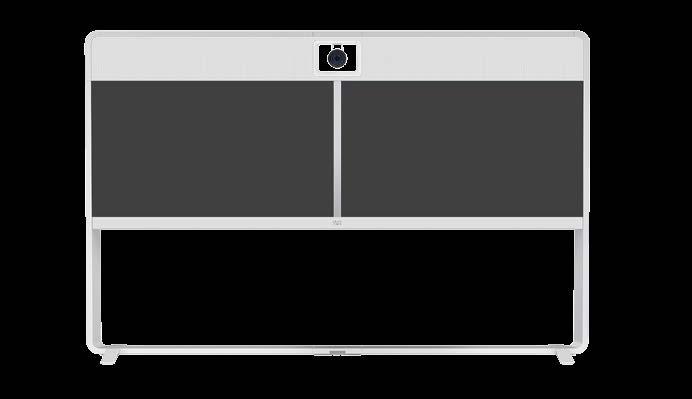
15 MX700 and MX800 at a glance (page 1 of 6) are part of the performance line within the Cisco portfolio of integrated video collaboration room systems. These systems integrate powerful functionality into an all-in-one solution for mediumto-large meeting rooms. The MX700 has two 55 LED monitors, MX800 Single has one 70 LED monitor, and MX800 Dual has two 70 LED monitors. The MX700 and MX800 systems come standard with a builtin amplifier and speaker system for high fidelity sound. You can choose from a single camera, or a dual camera speakertracking solution for MX700 and MX800 Single; MX800 Dual comes only with the dual camera speaker-tracking solution. Both cameras deliver the best possible video imaging with up to 20x zoom and 1080p60 resolution. Premium resolution and dual display are also standard features on the MX700 and MX800. The Cisco TelePresence Touch 10 provides an easyto-use interface for both MX700 and MX800 systems. MX700 with single camera Industry standards compliance lets the MX700 and MX800 support calls with any third party, standards-based system, including software-based video conferencing solutions. And, as the industry s first H.265-ready systems (in SIP calls), the MX700 and MX800 lay the foundation for future bandwidth efficiencies. MX800 Single with single camera MX700 with dual camera MX800 Single with dual camera MX800 Dual Features and benefits Ability to connect up to four HD input sources and eight microphones directly to the codec. One button to push (OBTP) to start a meeting. Ideal for team-based collaboration, boardrooms, meeting rooms and video centric rooms. Full duplex audio with high-quality sound in mono, and stereo. Dual presentation outside of a call (e.g. use the MX700 dual screens to compare two presentations or documents). Cisco TelePresence ClearPath packet loss protection technology. Built-in speaker tracking system as option. Optimal definition up to 1080p60. Native support for Cisco Unified Communications Manager (requires Cisco Unified Communications Manager version 8.6 or higher). Embedded MultiSite conferencing option that allows up to four additional participants (individual transcoding, no external bridge). H.323/SIP up to 6 Mbps point-to-point. Up to 10 Mbps total MultiSite bandwidth. Powerful and feature-rich video systems with ultimate video and audio quality. Four simultaneous video inputs. High performance video collaboration codec. 1080p60 main video and 1080p30 content. High-definition pan-tilt-zoom camera. Everything you need in one unit: screen(s), speakers, codec, camera, microphones. Three mounting options: wall mount, free standing floor stand, floor stand secured to the wall. 15
 Touch 10 user interface Wall mount")
16 MX700 and MX800 at a glance (page 2 of 6) MX700 with a single camera Camera Mounting options (20x zoom, 1080p60) Loudspeakers (full range multichannel and bass) Two 55 monitors Free standing floor stand Embedded codec Floor stand secured to the wall Microphones (default: two; maximum: eight) Touch 10 user interface Wall mount 16
 Loudspeakers (full range")
 Touch 10 user")
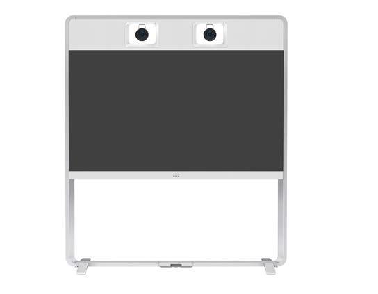
17 MX700 and MX800 at a glance (page 3 of 6) MX700 with dual camera Dual camera assembly Mounting options (speaker-track, 20x zoom, 1080p60) Loudspeakers (full range multichannel and bass) Two 55 monitors Free standing floor stand Embedded codec Floor stand secured to the wall Microphones (default: two; maximum: eight) Touch 10 user interface Wall mount 17
 70 monitor Free standing floor stand Embedded codec Floor stand secured to the wall Microphones (default: two; maximum: eight) Touch 10 user interface Wall")
18 MX700 and MX800 at a glance (page 4 of 6) MX800 Single with single camera Camera Mounting options (20x zoom, 1080p60) Loudspeakers (full range multichannel and bass) 70 monitor Free standing floor stand Embedded codec Floor stand secured to the wall Microphones (default: two; maximum: eight) Touch 10 user interface Wall mount 18

 70 monitor Free standing floor stand")
 Touch 10 user interface Wall")
19 MX700 and MX800 at a glance (page 5 of 6) MX800 Single with dual camera Dual camera assembly Mounting options (speaker-track, 20x zoom, 1080p60) Loudspeakers (full range multichannel and bass) 70 monitor Free standing floor stand Embedded codec Floor stand secured to the wall Microphones (default: two; maximum: eight) Touch 10 user interface Wall mount 19
 Loudspeakers (full range multichannel and")
 Touch 10 user interface Wall")
20 MX700 and MX800 at a glance (page 6 of 6) MX800 Dual Dual camera assembly Mounting options (speaker-track, 20x zoom, 1080p60) Loudspeakers (full range multichannel and bass) Two 70 monitors Free standing floor stand Embedded codec Floor stand secured to the wall Microphones (default: two; maximum: eight) Touch 10 user interface Wall mount 20
21 Power On and Off Power On/Off with the Power switch Power Off or restart the system remotely The power switch is behind the left side cover. Sign in to the web interface and navigate to > Restart. It is located in the same place for both MX700, MX800 Single and MX800 Dual, all mounting options. 1. Remove the left side cover. It snaps to magnets. Restart the system 2. The power switch is next to the power connector below the codec. Click Restart device... and confirm your choice. It takes a few minutes before the system is ready for use. Power Off the system Click Shutdown device... and confirm your choice. You cannot power On the system remotely. Power switch Restart and standby using the Touch controller Restart the system 1. Select the settings icon (cogwheel) in the status bar of the Touch controller. 2. Select Settings > Restart. 3. Select Restart again, and confirm your choice. Enter/exit standby mode 1. Select the settings icon (cogwheel) in the status bar of the Touch controller. 2. Select Standby. 21

22 LED indicators (page 1 of 3) MX700 System LED / Camera failure LED System LED / Camera failure LED This LED operates as both system LED and camera failure LED. Camera failure LED Codec LEDs Codec LEDs You must remove the side cover to be able to see the codec LEDs. You must remove the side cover to be able to see the codec LEDs. This LED operates as both system LED and camera failure LED for the right camera in a dual camera assembly. The side cover is fastened with magnets. The side cover is fastened with magnets. Sub-system failure LEDs Sub-system failure LEDs Sub-system failure LEDs Sub-system failure LEDs System LED Codec LEDs Camera failure LED Sub-system failure LEDs Blinking: System failure: Steady red light: There are four LEDs underneath the monitor(s). Normally, they are not lit. The video system is starting up. Pulsating: The video system is in standby mode. Lights steady (red) when there is a serious problem with the codec. The camera has a serious error. Power: Lights steady (white) when the codec has power. A steady red light indicates serious error, and you should contact the Cisco support organization. The LEDs mean (numbered from left to right): 1. Monitor failure. 2. Power failure for LCD monitor or camera sub-systems. 3. Power failure for audio sub-system. 4. Power failure for LCD monitor backlight. 22


23 LED indicators (page 2 of 3) MX800 Single System LED / Camera failure LED System LED / Camera failure LED This LED operates as both system LED and camera failure LED. Camera failure LED Codec LEDs Codec LEDs You must remove the side cover to be able to see the codec LEDs. You must remove the side cover to be able to see the codec LEDs. The side cover is fastened with magnets. The side cover is fastened with magnets. This LED operates as both system LED and camera failure LED for the right camera in a dual camera assembly. Sub-system failure LEDs Sub-system failure LEDs System LED Codec LEDs Camera failure LED Sub-system failure LEDs Blinking: System failure: Steady red light: There are four LEDs underneath the monitor(s). Normally, they are not lit. The video system is starting up. Pulsating: The video system is in standby mode. Lights steady (red) when there is a serious problem with the codec. The camera has a serious error. Power: Lights steady (white) when the codec has power. A steady red light indicates serious error, and you should contact the Cisco support organization. The LEDs mean (numbered from left to right): 1. Monitor failure. 2. Power failure for LCD monitor or camera sub-systems. 3. Power failure for audio sub-system. 4. Power failure for LCD monitor backlight. 23
24 LED indicators (page 3 of 3) MX800 Dual System LED / Camera failure LED Camera failure LED This LED operates as both system LED and camera failure LED for the right camera in a dual camera assembly. Codec LEDs You must remove the side cover to be able to see the codec LEDs. The side cover is fastened with magnets. Sub-system failure LEDs Sub-system failure LEDs System LED Codec LEDs Camera failure LED Sub-system failure LEDs Blinking: System failure: Steady red light: There are four LEDs underneath the monitor(s). Normally, they are not lit. The video system is starting up. Pulsating: The video system is in standby mode. Lights steady (red) when there is a serious problem with the codec. The camera has a serious error. Power: Lights steady (white) when the codec has power. A steady red light indicates serious error, and you should contact the Cisco support organization. The LEDs mean (numbered from left to right): 1. Monitor failure. 2. Power failure for LCD monitor or camera sub-systems. 3. Power failure for audio sub-system. 4. Power failure for LCD monitor backlight. 24
25 How to administer the video system (page 1 of 4) In general, we recommend you to use the web interface to administer and maintain the video system, as described in this administrator guide. Access method HTTP/HTTPS Alternatively, you can access the API of the video system by other methods: HTTP or HTTPS (also used by the web interface) SSH Telnet Serial interface (RS-232) If you want more information about the different access methods, and how to use the API, refer to the API guide for the video system. Tip If the configuration or status is available in the API, the web interface setting or status translates into an API configuration or status as follows: Set X > Y > Z to Value (web) is the same as x X Y Z: Value (API) Check X > Y > Z status (web) is the same as xstatus X Y Z (API) For example: Notes How to enable/disable the methods Used by the web interface of the video system NetworkServices > HTTP > Mode Non-secure (HTTP) or secure (HTTPS) communication Restart the video system for changes to take effect HTTP: Enabled by default HTTPS: Enabled by default Telnet SSH Serial interface (RS-232) Non-secure TCP/IP connection NetworkServices > Telnet > Mode Disabled by default You do not need to restart the video system. It may take some time for changes to take effect Secure TCP/IP connection NetworkServices > SSH > Mode Enabled by default You do not need to restart the video system. It may take some time for changes to take effect Connect to the video system with a cable. IPaddress, DNS, or a network is not required SerialPort > Mode Enabled by default We recommend using the default baud rate, because the video system may return much feedback (SerialPort > BaudRate) Restart the video system for changes to take effect For security reasons, you are asked to sign in by default (SerialPort > LoginRequired) If all access methods are disabled (set to Off), you can no longer configure the video system. You are not able to reenable (set to On) any of the access methods, and you must factory reset the video system to recover. Set SystemUnit > Name to MySystem is the same as x SystemUnit Name: MySystem Check SystemUnit > Software > Version status is the same as xstatus SystemUnit Software Version More settings and status are available in the web interface than in the API. 25


26 How to administer the video system (page 2 of 4) The web interface of the video system The web interface is the administration portal for the video system. You can connect from a computer and administer the system remotely. It provides full configuration access and offers tools and mechanisms for maintenance. Note: The web interface requires that HTTP or HTTPS is enabled (refer to NetworkServices > HTTP > Mode setting). Connect to the video system Open a web browser and enter the IP address of the video system in the address bar. How to find the IP address 1. Select the settings icon (cogwheel) in the status bar of the Touch controller. 2. Select Settings > System Information. We recommend that you use the latest release of one of the major web browsers. Sign in Enter user name and passphrase for the endpoint and click Sign In. The system is delivered with a default user named admin with no passphrase. Leave the Passphrase field blank when signing in for the first time. It is mandatory to set a password for the admin user. Sign out Hover the mouse over the user name and choose Signout from the drop-down list. 26
27 How to administer the video system (page 3 of 4) How the web interface is organized The web interface is organized in sub-pages. A user that is signed in, sees only the pages that he has access rights for. Read more about user administration, user roles and access rights in the User administration chapter. Main menu Home Call Control Setup Security Integration Users Diagnostics In-Room Control Status Server Certificates System Logs Startup Scripts CUCM Certificates Call Logs Developer API Personalization Certificate Authorities User Interface Screenshots Local Contacts Strong Security Mode Software Upgrade Room Types Sign In Banner Option Keys Presenter Tracking Non-persistent Mode Backup and Restore System Recovery Restart 27
28 How to administer the video system (page 4 of 4) Settings available on the Touch controller You have access to the following information and settings on the Touch controller: System information, call status, and diagnostics (available to all users) Restart of the video system (available to all users) Basic settings for sound, camera, main source, display, language (may or may not be protected by passphrase, refer to the UserInterface > UserPreferences setting) Basic settings for pairing, provisioning, network, IP and call protocols (always protected by passphrase) Access Settings 1. Tap the settings icon (cogwheel) in the status bar of the Touch controller. Settings Settings Ringtone & Sound Camera Control Main Source Selection Display Language System Information Call Status Diagnostics Restart Administrator > You have to enter the Username and Passphrase of the video system to open the Administrator settings. * Depending on product and product set-up, your Touch controller may or may not display the same menus as shown in the illustration. Use the UserInterface > UserPreferences setting to decide whether to keep these settings available for all users, or to move them to the passphrase protected area. > Available to all users Administrator Settings Call Details Provisioning Pairing IP & VLAN - Codec Network Status - Codec IP & VLAN - Touch Network Status - Touch SIP H323 Security EMC Resilience Reset Ringtone & Sound Camera Control Main Source Selection Display Language Date, Time & Location Call Details Provisioning Pairing IP & VLAN - Codec Network Status - Codec IP & VLAN - Touch Network Status - Touch SIP H323 Security EMC Resilience Reset Protected by passphrase Protected by passphrase UserInterface > UserPreferences: On (default) UserInterface > UserPreferences: Off Available to all users 2. Tap Settings. 3. Choose a category in the list*. Sign in to the video system s web interface, and navigate to Setup >. System Information Call Status Diagnostics Restart Administrator Administrator Settings Date, Time & Location 28
29 Chapter 2 29
30 User administration The default user account Edit an existing user account The endpoint comes with a default administrator user account with full access rights. The user name is admin and no passphrase is initially set. Change the user privileges It is mandatory to set a passphrase for the admin user. Read how to set the passphrase in the Change the system passphrase chapter. About user roles A user account may hold one or a combination of user roles. A user account with full access rights, like the default admin user, must possess all roles. 1. Sign in to the web interface, and navigate to Security > Users. These are the user roles: 2. Click the appropriate user in the list. ADMIN: A user with this role can create new users, change most settings, make calls, and search the contact lists. The user cannot upload audit certificates and change the security audit settings. 3. Choose user roles, set the status to Acitve or Inactive, and decide if the user has to change the passphrase on the next sign in. Fill in the Client Certificate DN (Distinguished Name) field only if you use certificate login on HTTPS. Create a new user account 1. Sign in to the web interface, and navigate to Security > Users. 2. Click Add new user Click Update User to save the changes. Use the Back button to leave without making any changes. 3. Fill in the Username and Passphrase input fields, and check the appropriate user roles check boxes. The USER and ADMIN roles have overlapping rights. * As a default, the user has to change the passphrase when he signs in for the first time. Fill in the Client Certificate DN (Distinguished Name) field only if you use certificate login on HTTPS. 4. Set the Status to Active to activate the user. USER: A user with this role can make calls and search the contact lists. The user can modify a few settings, for example adjust the ringtone volume and set the time and date format. Change the passphrase 1. Sign in to the web interface, and navigate to Security > Users. 2. Click the appropriate user in the list. 3. Enter the new passphrase in the appropriate input fields. AUDIT: A user with this role can change the security audit settings and upload audit certificates. The rights of the AUDIT user role do not overlap with the rights of the other roles. 4. Click Change Passphrase to save the change. Use the Back button to leave without making any changes. 5. Click Create User. Use the Back button to leave without making any changes. Delete the user account 1. Sign in to the web interface, and navigate to Security > Users. 2. Click the appropriate user in the list. 3. Click Delete <user name>... and confirm when prompted. * The passphrase protects the web and command line interfaces, and the Administrator settings on the Touch controller. 30

31 Change the system passphrase You need to know the system passphrase in order to: Sign in to the web interface Sign in and use the command line interfaces Access the Administrator settings from a Touch controller The default user account The video system is delivered with a default user account with full access rights. The user name is admin, and initially, no passphrase is set. Change your passphrase 1. Sign in to the web interface, hover the mouse over the user name, and choose Change Passphrase in the drop down list. 2. Enter the current passphrase and new passphrase in the input fields, and click Change passphrase. The passphrase format is a string with 0 64 characters. If the passphrase currently is not set, leave the Current passphrase field blank. It is mandatory to set a passphrase for the default admin user in order to restrict access to system configuration. It is also mandatory to set a passphrase for any other user with ADMIN rights. Keep a copy of the passphrase in a safe place. You have to factory reset the unit if you forget the passphrase. A warning, saying that the system passphrase is not set, is shown on screen until a passphrase is set for the admin user. Other user accounts You can create many user accounts for the video system. Read more about how to create and manage user accounts in the User administration chapter. Change another user s passphrase If you have administrator access rights, you can change the password of any user. 1. Sign in to the web interface, and navigate to Security > Users. 2. Click the appropriate user in the list. 3. Enter the new passphrase in the appropriate input fields. 4. Click Change Passphrase to save the change. Use the Back button to leave without making any changes. 31

32 System configuration Sign in to the web interface, and navigate to Setup >. Find a system setting Search for settings Change a system setting About system settings Check the value space All system settings can be changed from the web interface. A settings s value space is specified either by text following the input field or in a drop-down list that opens when you click the arrow. Each system setting is described in the chapter. Different settings may require different user credentials. In order to be sure that an administrator is able to change all system settings, an administrator user must possess all user roles. Enter as many letters as needed in the search field. All settings that contain these letters are shown in the right pane. Settings that have these letters in their value space are also shown. You can read more about user administration and user roles in the User administration chapter. Change a value 1. Choose the preferred value from the drop-down list, or enter new text in the input field. 2. Click Save for the change to take effect. Use the Undo or Cancel buttons if you do not want to make any changes. Select a category and navigate to settings The system settings are grouped in categories. Choose a category in the left pane to show the associated settings. Categories with unsaved changes are marked with an edit ). symbol ( 32


33 Add a sign in banner About sign in banner Sign in to the web interface, and navigate to Security > Sign In Banner. If a system administrator wants to provide initial information to all users, he can create a sign in banner. The message IS shown when the user signs in to the web interface or the command line interface. 1. Enter the message that you want to present to the user when he signs in. 2. Click Save to activate the banner. 33
34 Manage the service certificates of the video system Sign in to the web interface and navigate to Security > Service Certificates. You need the following files: Certificate (file format:.pem) Private key, either as a separate file or included in the same file as the certificate (file format:.pem format) Passphrase (required only if the private key is encrypted) The certificate and the private key will be stored in the same file on the video system. About the service certificates of the video system Certificate validation may be required when using TLS (Transport Layer Security). A server or client may require that the video system presents a valid certificate to them before communication can be set up. The video system s certificates are text files that verify the authenticity of the system. These certificates may be issued by a certificate authority (CA). Enable or disable, view or delete a certificate Certificates are used for the following services: HTTPS server, SIP, IEEE 802.1X and audit logging. Use the On and Off buttons to enable or disable a certificate for the different services. You can store many certificates on the video system, but only one certificate can be enabled for each service at a time. Use the corresponding button to view or delete a certificate. If authentication fails, the connection will not be established. Add a certificate 1. Click Browse... and find the Certificate file and Private key file (optional) on your computer. 2. Fill in the Passphrase if required. 3. Click Add certificate... to store the certificate on the video system. The certificates and certificate issuers in the illustration are examples. Your system has other certificates. 34
35 Manage the list of trusted certificate authorities (CAs) Sign in to the web interface, navigate to Security > Certificate Authorities, and open the Custom CAs tab. You need the following file: CA certificate list (file format:.pem). About trusted CAs Certificate validation may be required when using TLS (Transport Layer Security). The video system may be set up to require that a server or client presents its certificate to the video system before communication can be set up. The certificates are text files that verify the authenticity of a server or client. The certificates must be signed by a trusted CA. View or delete a certificate In order to verify the signature of the certificates, a list of trusted CAs must reside on the video system. Use the corresponding button to view or delete a certificate. The list must include all CAs needed in order to verify certificates for both audit logging and other connections. Upload a list of certificate authorities 1. Click Browse... and find the file containing a list of CA certificates on your computer (file format:.pem). 2. Click Add certificate authority... to store the new CA certificates on the video system. If authentication fails, the connection will not be established. The certificates and certificate issuers in the illustration are examples. Your system has other certificates. Previously stored certificates are not deleted automatically. The entries in a new file with CA certificates are appended to the existing list. 35
 that verifies the certificate of the audit server must be in the video system s list of trusted certificate authorities.")
36 Set up secure audit logging Sign in to the web interface, navigate to Setup >. The certificate authority (CA) that verifies the certificate of the audit server must be in the video system s list of trusted certificate authorities. Otherwise, logs will not be sent to the external server. Refer to the Manage the list of trusted certificate authorities (CAs) chapter how to update the list. About secure audit logging When audit logging is enabled, all sign in activity and configuration changes on the video system are recorded. Use the Security > Audit > Logging > Mode setting to enable audit logging. Audit logging is disabled by default. In ExternalSecure audit logging mode the video system sends encrypted audit logs to an external audit server (syslog server), which identity must be verified by a signed certificate. 1. Open the Security category. 2. Find the Audit > Server settings, and enter the Address of the audit server. The signature of the audit server is verified using the same CA list as other servers/clients. If you set PortAssignment to Manual, you must also enter a Port number for the audit server. If the audit server authentication fails, no audit logs are sent to the external server. Click Save for the changes to take effect. 3. Set Audit > Logging > Mode to ExternalSecure. Click Save for the change to take effect. 36
37 Manage pre-installed certificates for CUCM via Expressway provisioning About pre-installed certificates Sign in to the web interface, navigate to Security > Certificate Authorities, and open the Preinstalled CAs tab. The pre-installed certificates in this list are only used when the video system is provisioned by Cisco Unified Communications Manager (CUCM) via Expressway (Edge). Only Cisco Expressway infrastructure certificates are checked against this list. If the validation of the Cisco Expressway infrastructure certificate fails, the video system will not be provisioned and registered. Factory resetting the video system does not delete the list of pre-installed certificates. View or disable certificates Use the Details... and Disable buttons respectively, to view or disable certificates. The certificates and certificate issuers in the illustration are examples. Your system has other certificates. As an alternative to using the pre-installed certificates, you can append the certificates you need to the certificate list manually. Refer to the Manage the list of trusted certificate authorities (CAs) chapter how to update the list of trusted certificates. 37
38 Delete CUCM trust lists The information in this chapter is only relevant for video systems that are registered to a Cisco Unified Communications Manager (CUCM). Sign in to the web interface, navigate to Security > CUCM Certificates. More information about trust lists Delete the CUCM trust lists For more information about CUCM and trust lists, read the Deployment guide for TelePresence endpoints on CUCM that is available on the Cisco web site. Click Delete CTL/ITL to remove the trust lists. As a general rule, you should not delete old CTL (Certificate Trust List) and ITL (Initial Trust List) files. In these cases, you must still delete them: When you change the CUCM IP address. When you move the endpoint between CUCM clusters. When you need to re-generate or change the CUCM certificate. Overview of trust list fingerprints and certificates The trust lists fingerprints and an overview of the certificates in the lists are displayed on the web page. This information may be useful for troubleshooting. 38
39 Change the persistency mode About persistency mode Sign in to the web interface, navigate to Security > Non-persistent Mode. Check the persistency status The active radio buttons show the current persistency status of the video system. Alternatively, navigate to Setup > Status > Security > Persistency to see the status. Change the persistency settings 1. Click the radio buttons to set the persistency for configurations, call history, internal logging, local phonebook (local directory and favorites) and IP connectivity (DHCP) information. 2. Click Save and reboot... The video system restarts automatically. After the restart, the behavior changes according to the new persistency settings. Logs, configurations and other data that was stored before the switch to Non-persistent mode, are NOT cleared or deleted. By default, all persistency settings are set to Persistent. This means that configurations, call history, internal logs, local phonebook (local directory and favorites list) and IP connectivity information are stored as normal. A system restart does not delete this information. As a general rule, we recommend NOT to change the default settings for persistency. Non-persistent mode must be used in situations where a user is not supposed to see or trace back to any kind of logged information from the previous session. In Non-persistent mode, the following information is lost or cleared each time the system restarts: System configuration changes Information about calls that are placed or received (call history) Internal log files Changes to the local contacts or favorites list All IP related information (DHCP) from the last session In order to clear/delete information that was stored before changing to Non-persistent mode, you should factory reset the video system. There is more information about performing a factory reset in the Factory reset the video system chapter. 39

40 Set strong security mode About strong security mode Sign in to the web interface, navigate to Security > Strong Security Mode. Use strong security mode only when compliance with DoD JITC regulations is required. Strong security mode sets very strict passphrase requirements, and requires all users to change their passphrase on the next sign in. Set strong security mode Read carefully about the consequences of strong security mode before you continue. 1. If you want to use strong security mode, click Enable Strong Security Mode... and confirm your choice in the dialog box that appears. The video system restarts automatically. 2. Change the passphrase when you are prompted. The new passphrase must meet the strict criteria as described. How to change the system passphrase is described in the Change the system passphrase chapter. Return to normal mode Click Disable Strong Security Mode... in order to restore the video system to normal mode. Confirm your choice in the dialog box that appears. The video system restarts automatically. 40
41 Set up Intelligent Proximity for content sharing (page 1 of 4) Cisco Proximity allows users to see, control, capture and share content directly on their own mobile devices (smartphone, tablet, or laptop), when the device is near a video system. The mobile device can automatically pair with the video system when it comes within range of ultrasound transmitted by the video system. Proximity services Place calls and control the video system: Dial, mute, adjust volume, hang up Available on smartphones and tablets (ios and Android) View shared content on a mobile device: View shared content, review previous slides, save selected slides Available on smartphones and tablets (ios and Android) Wireless share from a mobile device: Share content without connecting a presentation cable Available on laptops (OS X and Windows) The number of simultaneous Proximity connections depends on the type of video system. The client warns new users if the maximum number of connections has been reached. Video system Maximum number of connections SX80 10 SX20 7 SX10 MX700, MX800 MX200 G2, MX300 G Place calls and control the video system View shared content on a mobile device 7 Wireless share from a mobile device 41
42 Set up Intelligent Proximity for content sharing (page 2 of 4) About ultrasound Install a Cisco Proximity client Cisco video systems emit ultrasound as part of the Proximity feature. Where to find the clients Most people are exposed to ultrasound more or less daily in many environments, including industry, commercial applications and home appliances. You can download the Cisco Proximity clients for smartphones and tablets (Android and ios), and laptops (Windows and OS X) free of charge from MX Series Clients for smartphones and tablets are also available directly through Google Play (Android) and Apple App Store (ios). In our integrated MX Series systems, the ultrasound sound pressure level is below 75 db at a distance of 75 cm or more from the loudspeaker. Even if airborne ultrasound may cause subjective effects for some individuals, it is very unlikely that any effects will occur for levels below 75 db. SX Series For SX Series systems, which use third-party loudspeakers, we do not know the sound pressure level. The volume control on the remote control or Touch controller does not affect the ultrasound sound pressure level; only the volume control on the loudspeaker itself, and the > Pairing > Ultrasound > Volume > MaxLevel setting has an effect. End-user license agreement Read the end-user license agreement carefully, English/EU1KEN_.html Supported operating systems ios 7 and above Android 4.0 and above Mac OS X 10.9 and above Windows 7 and above The tile based interface introduced with Windows 8 is not supported. The client is launched as a public Beta. Headsets We do not know the sound pressure level for headsets. Therefore we recommend not to use a headset with MX Series and SX Series video systems, if you have switched on Proximity (ultrasound). 42
43 Set up Intelligent Proximity for content sharing (page 3 of 4) Enable the Proximity services Disable Proximity temporarily About Proximity All Proximity services are disabled by default. You can temporarily disable Proximity in a meeting. This is useful in meetings where you want to prevent devices in the room from receiving content. When Proximity is switched On, the video system transmits ultrasound pairing messages. 1. Sign in to the web interface, and navigate to Setup >. 2. Go to Proximity > Mode. Check that Proximity is On (default), so that the video system sends ultrasound pairing messages. 3. Enable the services you want to allow. 1. Select the settings icon (cogwheel) in the status bar of the Touch controller. The Proximity feature is switched On by default. 2. Switch Proximity on or off with the toggle button. The ultrasound pairing messages are received by nearby devices with Proximity clients, and triggers the authentication and authorization of the device. In order to fully utilise the Proximity functionality, we recommend that you enable all services. Place calls and control the video system: Go to Proximity > Services > CallControl and choose Enabled. View shared content on a mobile device: Go to Proximity > Services > ContentShare > FromClients and choose Enabled. Wireless share from a mobile device: The Proximity indicator The Proximity indicator is shown on both the main display and the Touch controller. Proximity is On, and at least one service is enabled. The Proximity feature is temporarily disabled. For the best user experience, Cisco recommends that Proximity always is switched On*. In order to get full access to Proximity, the Proximity services (Proximity > Services >...) must be Enabled as well. Go to Proximity > Services > ContentShare > ToClients and choose Enabled. * 43 We recommend not to use a headset, if you have switched on Proximity (ultrasound).
44 Set up Intelligent Proximity for content sharing (page 4 of 4) Room considerations Room acoustics Rooms with hard surfaces may cause challenges due to severe audio reflections. Acoustical treatment of meeting rooms is always highly recommended for the best meeting experience as well as Intelligent Proximity performance. Cisco recommends only one video system with Intelligent Proximity enabled in a room. Otherwise, interference is likely to occur, which may lead to problems with device discovery and session maintenance. Basic troubleshooting About privacy Additional resources In the Cisco Privacy statement and the Cisco Proximity Supplement you find information about data collection in the clients and privacy concerns that needs to be considered when deploying this feature in the organization. Refer to: Cisco Intelligent Proximity site: Support forum: You can temporarily disable Proximity in a meeting from the Touch controller. This is useful in meetings where you want to prevent devices in the room from receiving content. You cannot temporarily disable Proximity if using the TRC6 remote control. Cannot detect devices with Proximity clients Some Windows laptops are not able to record sound in the ultrasound frequency range (20 khz-22 khz). This can be due to frequency limitations with the sound card, sound driver or the internal microphone of the particular device. Refer to the Support forum for more information. Audio artifacts If you can hear audio artifacts, like humming or clipping noise, decrease the maximum ultrasound volume ( > Pairing > Ultrasound > Volume > MaxLevel). 44
45 Adjust the video quality to call rate ratio Optimal definition profile The optimal definition profile should reflect the lighting conditions in the video conferencing room and the quality of the camera (video input source). The better the lighting conditions and the better the quality of the camera, the higher the profile should be used. In good lighting conditions, the video encoder will provide better quality (higher resolution or frame rate) for a given call rate. Sign in to the web interface and navigate to Setup >. 1. Go to Video > Input > Connector n > Quality and set the video quality parameter to Motion. 2. Go to Video > Input > Connector n > OptimalDefinition > Profile and choose the preferred optimal definition profile. 3. Go to Video > Input > Connector n > OptimalDefinition > Threshold60fps to set the threshold below which the maximum transmitted frame rate will be 30 fps. Generally, the Medium profile is recommended. However, if the lighting conditions are very good, we recommend that you test the endpoint on the various Optimal Definition Profile settings before deciding on a profile. The High profile may be set in order to increase the resolution for a given call rate. Some typical resolutions used for different optimal definition profiles, call rates and transmit frame rates are shown in the table. The resolution and frame rate must be supported by both the calling and called systems. Typical resolutions used for different optimal definition profiles, call rates and frame rates Optimal Definition Profile 30 fps Medium High H.265 (only in SIP calls) Threshold for sending video at 60 fps Use the Video Input Connector n OptimalDefinition Threshold60fps setting to decide when to allow sending video at 60 fps. For all resolutions lower than this threshold, the maximum transmitted frame rate will be 30 fps; for higher resolutions, 60 fps is possible if the available bandwidth is adequate. 60 fps H.264 The Video Input Connector n Quality setting must be set to Motion for the optimal definition settings to take any effect. With the video input quality set to Sharpness, the endpoint will transmit the highest resolution possible, regardless of frame rate. Normal 30 fps Video input quality settings 60 fps 768 kbps 1152 kbps 1472 kbps 2560 kbps 4 Mbps* 6 Mbps* Normal Medium High Normal Medium High Normal Medium High * Call rate Frame rate H.265 is preferred over H.264, and the maximum bit rate for H.265 is 3 Mbps. When the user sets a higher bit rate, the codec will still use H.265 at 3 Mbps as long as all codecs involved supports H
46 Packet loss resilience - ClearPath ClearPath introduces several mechanisms for advanced packet loss resilience. These mechanisms increase the experienced quality when you use your video system in an error prone environment. ClearPath is a Cisco proprietary protocol. All endpoints running CE software support ClearPath. If the involved endpoints and infrastructure elements support ClearPath, all packet loss resilience mechanisms are used in point-to-point connections (including hosted conferences). Only some of the mechanisms are supported in MultiSite conferences. 46

47 Choose wallpaper About a custom wallpaper Sign in to the web interface, and navigate to Setup > Personalization. If you want the company logo or another custom picture as background on the main display, you may upload and use a custom wallpaper. You can only store one custom wallpaper on the video system at a time; a new custom wallpaper overwrites the old one. Choose wallpaper When you use a custom wallpaper, these items are removed from the main display: Choose a wallpaper from the list. The active wallpaper is highlighted. The clock The list of upcoming meetings Upload a custom wallpaper Overwrites any old custom wallpaper. 1. Click Browse... and locate the custom wallpaper image file. 2. Click Upload to save the file on the video system. Delete the custom wallpaper Supported file formats: BMP, GIF, JPEG, PNG Delete fully removes the custom wallpaper from the video system. Maximum file size: 4 MByte You have to upload it anew if you want use it again. The custom wallpaper is automatically activated once uploaded. 47
48 Choose ringtone About ringtones Sign in to the web interface, and navigate to Setup > Personalization. A set of ringtones are installed on the video system. You should use the web interface to chose a ringtone, and set the ringtone volume. You can play back the chosen ringtone from the web interface. Note that the ringtone will be played back on the video system itself, and not on the computer running the web interface. Change the ringtone 1. Choose a ringtone from the drop-down list. 2. Click Save to make it the active ringtone. Play back the ringtone Set the ringtone volume Click the play button ( ) to play back the ringtone. Use the slide bar to adjust the ringtone volume. Use the stop button ( ) to end the playback. 48
49 Manage local contacts Sign in to the web interface and navigate to Setup > Local Contacts. Where to find the local contacts Import/Export contacts from file Touch controller: Tap Contacts > Favorites to find all local contacts. Click Export to save the local contacts in a file; and click Import to bring in contacts from a file. Web interface: Click Call Control, and open the Local tab in the Contacts section. The current local contacts are discarded when you import new contacts from a file. Add or edit a contact 1. Click Add contact to make a new local contact, or click a contact s name followed by Edit contact. 2. Fill in or update the form that pops up. Choose a folder in the folder drop down list in order to store the contact in a sub-folder. Click Add contact method and fill in the new input fields if you want to store more than one contact method for the contact (for example video address, telephone and mobile number). 3. Click Save to store the local contact. Delete a contact 1. Click a contacts name followed by Edit contact. 2. Click Delete to remove the local contact. Add or edit a sub-folder 1. Click Add folder to make a new sub-folder, or click one of the listed sub-folders followed by Edit folder to change an existing sub-folder. 2. Fill in or update the form that pops up. 3. Click Save to create or update the folder. Delete a sub-folder 1. Click Edit folder. 2. Click Delete to remove the folder and all its contacts and sub-folders. Confirm your choice in the dialog that pops up. 49
50 Chapter 3 50
51 Connect external monitors (page 1 of 3) MX700 and MX800 Dual support one external monitor, and MX800 Single supports two external monitors, in addition to the video systems integrated monitor(s). MX700 and MX800 Dual The video system distributes the layout on all available monitors. External monitor Always switch off power when you connect and disconnect monitors and other peripherals. Remove the video system s left side cover to get access to the codec connector panel and power switch. The cover is fastened with magnets. Connector 3 (DVI-I) Audio Line outputs (Euroblock, 3.5 mm) Do not disconnect the integrated monitors from the codec, and do not use those connectors for anything else. The reason for this is that the integrated monitor connections make use of multichannel audio, which drives the included speaker systems. Inserting third party equipment is likely to break the audio chain, causing the video system to fail from an audio perspective. Codec connector panel These connectors are used for the integrated monitors. Do not disconnect! MX800 Single External monitor Connector 3 (DVI-I) Audio Line outputs (Euroblock, 3.5 mm) Connector 2 (HDMI) External monitor Codec connector panel 51 This connector is used for the integrated monitor. Do not disconnect!
52 Connect external monitors (page 2 of 3) Automatic setup There is no special configuration needed on the video system in order to support dual monitors or triple monitors scenarios. By default the number of monitors are auto-detected, and the role of each monitor - whether it is intended to be the first, second, or third monitor - is automatically set according to the physical connections. For example, if the total number of monitors are three, the following settings will be assumed when set to Auto: Video > Monitors : Triple Video > Output > Connector 1 > MonitorRole : First Video > Output > Connector 2 > MonitorRole : Second When do you need manual setup You can override the default behavior by setting one or more settings manually. You need manual setup when you want to: Dedicate a monitor to only show presentations Use one of the outputs for a recorder Replicate the same layout on more than one monitor Show the on-screen messages and indicators (OSD) on another monitor than the video output with the lowest number Set the resolution manually, e.g. if the video system fails to detect the native resolution and refresh rate of a monitor Video > Output > Connector 3 > MonitorRole : Third These settings can be changed if necessary, but for ease of use no configuration is required in order to use the default values. 52
53 Connect external monitors (page 3 of 3) Manual setup About the number of monitors and the role of each monitor The automatic setup works well for common single monitor, dual monitors, and triple monitors scenarios. For more complex scenarios, you may need manual configuration. The Video > Output > Connector n > MonitorRole setting assigns a role to the monitor that is connected to the output. The monitor role decides which layout (call participants and presentation) will appear on the monitor. Sign in to the web interface and navigate to Setup >, to find the settings referred below. Set a role for each monitor Set the number of monitors Define a role for each monitor with the Video > Output > Connector n > MonitorRole setting. Set the number of monitors with different layouts in your setup with the Video > Monitors setting. Choose monitor roles that match your monitor setup. When set to Auto, the codec automatically detects if a monitor is connected to a connector, and thereby also determines the number of monitors in the setup. Choose on which monitor to display messages and indicators Set the monitor resolution and refresh rate Define on which monitor to display the messages and indicators on-screen with the UserInterface > OSD > Output setting. The video system reads the native resolution of a monitor and outputs this if possible. Typically, this gives the best possible picture for the monitor. When set to Auto, the video system determines which monitor to use based on the number of the connector. The other options allow you to fix a single, dual, or triple monitor setup; and to dedicate one monitor for presentations. Example 1: Three monitors in total, and the third monitor is dedicated to only show presentations: If auto-detection of resolution and refresh rate fails, you must set the resolution manually with the Video > Output > Connector n > Resolution setting. Monitors with the same monitor role get the same layout; monitors with different monitor roles have different layouts. The Video > Monitors setting must reflect the number of different layouts in your room setup. Most often the number of different layouts are the same as the number of physical monitors, but not always; if exactly the same layout shall be repeated on two or more monitors, the number of different layouts are less. Note that a monitor can be reserved for presentations. Example 2: Two monitors in total, and a recording device is attached to Connector 3 (DVI). OSD on the monitor on Connector 2: Video > Monitors : TriplePresentationOnly Video > Monitors : Auto Video > Output > Connector 1 > MonitorRole : Auto Video > Output > Connector 1 > MonitorRole : Auto Video > Output > Connector 2 > MonitorRole : Auto Video > Output > Connector 2 > MonitorRole : Auto Video > Output > Connector 3 > MonitorRole : Auto Video > Output > Connector 3 > MonitorRole : Recorder UserInterface > OSD > Output : Auto UserInterface > OSD > Output : 2 53
54 Three for single camera systems Two for dual camera systems Connect input sources You can connect several external input sources to the video system simultaneously: (page 1 of 2) About the video inputs Audio Line input (Euroblock, 3.5 mm) C Connector 5 (S-Video/Composite) Y Two HDMI inputs (video systems with a single camera) / One HDMI input (video systems with a dual camera) One DVI-I input One combined S-video/Composite video input Connector 4 (DVI-I) Sign in to the web interface and navigate to Setup >, to find the settings referred in this section. Connector 3 (HDMI) Connector 2 (HDMI) Remove the video system s left side cover to get access to the connectors. The cover is fastened with magnets. Connector 1 (HDMI) Do not disconnect! Used for the integrated cameras in a dual camera system. Do not disconnect! Used for the integrated camera in a single camera system. Connect a camera Connect a computer Analog video input Typically, an external camera is connected to an HDMI input. Connect a computer to a video input in order to share content locally or with conference participants. The codec supports two computers simultaneously. Connector 5 comprises two BNC sockets, and is used for S-Video or Composite video signals. In addition, you must connect the camera via an Ethernet switch to the video system s Ethernet 2 or Ethernet 3 port; or to the camera control DSUB-9 port. The type of camera determines whether to use Ethernet or DSUB-9. MX700 and MX800 has several input connectors. The following inputs are available for additional content sources: The DVI-I and combined S-Video/ Composite video inputs cannot be used simultaneously. Typically, the inputs are used for computers, but you can also connect cameras or other types of video and content sources. S-Video: Connect to both the Y and C connectors. Typically, computers are connected to Connector 3 (HDMI) or Connector 4 (DVI-I). Composite: Connect to the Y connector. To get audio when using DVI-I, you must also connect the computer to one of the codec s Audio Line inputs (Euroblock). 54
55 Connect input sources (page 2 of 2) About video and content quality Set type and name for the input sources Use the Video > Input > Connector n > Quality setting to optimize quality with respect to motion or sharpness. We recommend that you set type and name for the input sources: Typically, you should choose Motion when a large number of participants are present or when there is a lot of motion in the picture. Choose Sharpness when you want the highest quality of detailed images and graphics. The default value is Motion for Connector 2; and Sharpness for Connector 3 and 4. Video > Input > Connector n > InputSourceType Video > Input > Connector n > Name These settings determine the names and icons that are shown on the user interfaces. Intuitive names and icons make source selection easier. 55
56 Set up the SpeakerTrack feature Sign in to the web interface and navigate to Setup >, to find the settings referred. Tracking mode About speaker tracking The tracking mode defines how fast the camera view switch to a new speaker when the tracking algorithm detects a change. The following Cisco TelePresence products support speaker tracking: Use the Cameras > SpeakerTrack > Mode setting to enable or disable speaker tracking. Use the Cameras > SpeakerTrack > TrackingMode setting to select between the two modes. Off: Speaker tracking is switched off permanently. Auto: This is the default setting. Auto: Speaker tracking is enabled in general. Users can switch it on or off instantly in the camera control panel on the Touch controller. Conservative: The system reacts slower to detected changes, and the camera view will switch to a new speaker later. You can also use the Administrator Settings menu on the Touch controller to switch between the two tracking modes. Tap Settings > Administrator and sign in. Tap Tracking, and set Tracking Mode to NORMAL (auto) or CONSERVATIVE. MX700 and MX800 with dual camera SpeakerTrack 60 camera The two cameras in the assembly work together with a built-in microphone array to automatically track and show the person that speaks. 56

57 Set up the Snap to Whiteboard feature (page 1 of 3) The Snap to Whiteboard feature extends the speaker tracking functionality, thus you need a camera that supports SpeakerTrack: MX700 and MX800 with dual camera, or SX80 with SpeakerTrack 60 camera Preparations Whiteboard position Cameras > SpeakerTrack > Mode must be set to Auto, and speaker tracking must be switched on with the Touch controller. With the Snap to Whiteboard extension, the camera captures both the person and the whiteboard when a person next to the whiteboard talks. Speaker position Speaker track camera Sound tracking area Accurate distance (d) between camera and whiteboard d Whiteboard Without the Snap to Whiteboard extension, the camera captures only the person. The whiteboard must be placed across the room from the camera, as shown in the illustration. The Sound tracking area is from half the whiteboard and up. When configuring the feature, you need to know the accurate distance between the camera and the whiteboard. Thus, the person presenting on the whiteboard must stand upright next to the whiteboard. He or she cannot move about in the room. 57
 in the status bar of the Touch controller and open the Settings menu. Troubleshooting 5.")
58 Set up the Snap to Whiteboard feature (page 2 of 3) Define the whiteboard area Use the wizard on the Touch controller to define the whiteboard area. 1. Tap the settings icon (cogwheel) in the status bar of the Touch controller and open the Settings menu. Troubleshooting 5. Follow the instructions in the wizard - use the back button, if you want to redo a step: Set the distance between the camera and the whiteboard. Slide the circle to the correct distance on the ruler. If the camera does not move to the whiteboard position when the person who is talking stands next to the whiteboard, check the following and redo the required steps in the wizard: 2. Tap Administrator, and sign in with administrator credentials. 3. Tap Tracking. Check that the whiteboard is placed across the room from the camera. Check that the distance between the camera and whiteboard is measured accurately. The person who is talking must be close to the whiteboard. Furthermore, the person must stand upright so that the sound comes from the upper half of the whiteboard area. 4. Tap Configure Snap to Whiteboard or Reconfigure Snap to Whiteboard to start the wizard (depends whether you configure the feature for the first time or not). It is important that the distance is measured accurately. Position the camera (pan, tilt, zoom) to frame the whiteboard as accurate as possible. Fine tune the position (pan, tilt, zoom) of both cameras so that they show the same image. Stand by the whiteboard and start talking. If the feature is correctly configured, the camera will move to a position that covers both the whiteboard and the person that is talking. When you have completed the wizard, the Snap to Whiteboard feature is ready for use. 58

59 Set up the Snap to Whiteboard feature (page 3 of 3) Enable and disable Snap to Whiteboard An administrator can enable and disable the Snap to Whiteboard feature, either using the Touch controller or the web interface. The feature cannot be switched on and off by the user, neither during a meeting, nor between one meeting and the next. 1. Tap the settings icon (cogwheel) in the status bar of the Touch controller and open the Settings menu. Switch on and off speaker tracking Speaker tracking, which can be switched on and off by the user at any time, must be switched on for the Snap to Whiteboard extension to work. Tap the camera icon in the status bar of the Touch controller, and use the toggle button to switch speaker tracking on and off. 2. Tap Administrator, and sign in with administrator credentials. 3. Tap Tracking. 4. Set Snap to Whiteboard to ON if you want the camera to capture both the person that talks and the whiteboard he or she is standing next to. Set Snap to Whiteboard to OFF if you want only the person that talks to be captured. Alternatively, use the Cameras > SpeakerTrack > Whiteboard > Mode setting on the web interface to switch the Snap to Whiteboard feature On and Off. 59


60 Set up the PresenterTrack feature The PresenterTrack feature enables the camera to follow the presenter, while the presenter moves about on stage. When the presenter leaves the stage the tracking stops. A system administrator must define the stage area and the trigger zone. We recommend you to be in the room while setting up PresenterTrack. Prerequisites MX700 or MX800 with single or dual camera, SX80 with Precision 60 camera, or SX80 with SpeakerTrack 60 camera Plan the room and the stage area Plan the trigger zone Consider where to place the camera, that is used for presenter tracking, to obtain an optimal user experience. The trigger zone is the area where presenter tracking is triggered. The trigger zone must cover an area that enables the detection of a presenter's face. Allow the audience or meeting participants to move naturally in the room, without being tracked unintended. The stage area is the zoomed-out overview image. Make it large enough so the presenter can move about on stage. When the presenter leaves the stage area the tracking stops. Supports only one person in the cropped image. Can be used in combination with Briefing Room mode. You can use one of the SpeakerTrack 60 cameras for PresenterTrack. The camera uses digital pan, tilt and zoom, so it will not move physically. PresenterTrack and SpeakerTrack cannot be used simultaneously. When you activate PresenterTrack SpeakerTrack is disabled, and vice versa. Choose a location where the presenter naturally will enter the stage, for example by the speakers podium or presenters desk. The trigger zone is not visible for the person coming up on stage, so make it easy for the person to be detected. To avoid false face detection, make sure the background of the trigger zone is neutral. Avoid having the trigger zone in front of a monitor. PrestenterTrack feature (page 1 of 5) The PresenterTrack is supported with: Stage area 60 Trigger zone
61 Set up the PresenterTrack feature (page 2 of 5) Step 1: Position the camera Tip We recommend that you are in the room when you configure the PresenterTrack feature. Use the Touch controller to adjust the camera (zoom, pan, tilt) to define the stage area. Use the video system's web interface to define the trigger zone. At the same time, watch the screen of the video system to see the result. Activate the PresenterTrack feature from the camera panel on the Touch controller. Sign in to the web interface: 1. Navigate to Setup > Presenter Tracking. 2. Check the Enable PresenterTrack check box. 3. Click Configure... to open the configuration page. When you click the Configure... button on the video system's web interface, this will happen: Standby is deactivated. Full screen self-view is enabled. The trigger zone rectangle is shown on screen. If already active, the PresenterTrack feature is deactivated. Stage area: The zoomed out overview image. Make it large enough so that the presenter can move around. When the presenter leaves the stage area the tracking stops. Note that if you leave this web page at this stage, without doing any changes, the trigger zone rectangle is still visible on the video system's screen. If you are not in the room: Click the Save button to remove the trigger zone rectangle on the screen. If you are in the room: Tap the Camera icon on the Touch controller and choose a camera position from the list. 4. Choose a camera from the Camera source drop down list. A Precision 60 or SpeakerTrack 60 camera is required to enable the PresenterTrack feature. If the camera does not meet the requirements you will see a notification. 5. Define the stage area. Use the Touch controller to adjust the full screen self-view (zoom, pan, tilt) if necessary. The camera must cover the stage area that is used by a presenter. When the presenter leaves the stage the camera will stop following the presenter. 61
62 Set up the PresenterTrack feature (page 3 of 5) Step 2: Set the trigger zone The trigger zone defines the area where presenter tracking is triggered. You cannot see the video from the room in the web interface. An empty gray area represents the camera view and a dashed rectangle represents the trigger zone. Watch the video system screen to see the video from the room, together with the same dashed rectangle as you see in the web interface. Adjust the size and location of the trigger zone to cover a suitable area to detect a presenter's face. The change you do on the video system's web interface is reflected on the video system screen. The trigger zone must be large enough to detect a presenter face. Have in mind that people are of different heights. Trigger zone Video system screen: See the video from the room when you set the trigger zone. Click Save. Stage area The zoomed out overview image of the room is represented by a blank box in the video system's web interface. Trigger zone The dashed rectangle can be moved around and re-sized. You can see the same rectangle on the endpoint screen when you define the trigger zone. Web interface: Set the trigger zone. 62
63 Set up the PresenterTrack feature (page 4 of 5) Step 3: Test PresenterTrack in action User scenarios Activate PresenterTrack. We do not support tracking of more than one person, but sometimes more than one person is in the cropped image. 1. Tap the Camera icon in the upper right corner of the Touch controller. 2. Select Presenter from the list of camera positions to activate presenter tracking. 3. The camera is now ready for presenter tracking, and you can test the feature: a. Position yourself in the trigger zone. b. When you are detected the camera zooms in on you. Walk back and forth on stage and check that the camera follows you. a. Position yourself in the trigger zone. When multiple faces are in the cropped image, the faces will be tracked as long as they all move in the same direction. If they move in different directions the tracking stops and the image zooms out and show the stage area. To start the presenter tracking again, the presenter must go to the trigger zone to be detected. Scenario 1: A person is interviewed by another. They are both followed by the camera as long as they stand still or move in the same direction. c. Leave the stage area to stop presenter tracking. If necessary, go back to Step 1 or Step 2 to adjust the size of the stage area or the trigger zone. Scenario 2: When a presenter is replaced by another the tracking stops. The new presenter must move into the trigger zone to be detected by the camera. b. The camera zooms in on the presenter. If you need to disable, and thereafter enable, presenter tracking in a controlled manner this can be done on the Touch controller. 1. Tap the Camera icon in the status bar. 2. Deselect Presenter from the list of camera positions to disable PresenterTrack, and select Presenter again to enable the feature. c. Leave the stage to stop presenter tracking. 63
64 Set up the PresenterTrack feature (page 5 of 5) Diagnostics mode In order to troubleshoot you can set the video system in PresenterTrack diagnostics mode. The green square indicates the at face is tracked. Sign in to the xapi and run the following command. The blue square indicates the at face is detected but not tracked. xcommand Cameras PresenterTrack Set Mode: Diagnostic In diagnostics mode the video system screen shows the stage area (the zoomed out overview image), and the indicators: RED: The trigger zone. The red rectangle is the trigger zone. YELLOW: The cropped image that shows a zoomed in view of the presenter. GREEN: A face is detected and it is tracked. GREEN BLINKING, FILLED: Indicates a positive face detection. If the tracked individual does not get a valid face-read the square will become red. RED BLINKING, FILLED: Indicates a false face detection. After some seconds the tracking will stop. BLUE: A face is detected but the face is not tracked. The yellow rectangle is the cropped image that follows the presenter. The yellow rectangle is not visible until a person steps into the trigger zone and is being tracked. 64
65 Briefing room set-up (page 1 of 3) The briefing room set-up is designed to provide easy set up, management and use of a room for education, training or similar. The set-up is tailored around the following room modes: Local Presenter (the presenter is in the room) Remote Presenter (the presenter is calling in) Discussions (for discussions between different sites with local presenter in the room) Presentation display Remote presenter display Audience camera (single or dual) Remote audience display Presenter camera The briefing room is available as a room type template, which means that the required configurations are pushed automatically to the video system when you select the template. Microphones In order for these configurations to match the room, it is important that the room is set up correctly, and that cameras and displays are connected exactly as specified in this chapter. Remote presenter display Required equipment Video system: MX700 or MX800 with Touch 10. Three displays: They are referred to as Presentation display, Remote presenter display, and Remote audience display (see blue print to the right). Two cameras: They are referred to as Audience camera, and Presenter camera (see blue print to the right). We recommend using the integrated camera as Audience camera. We recommend Cisco TelePresence Precision 60 as Presenter camera. Presentation display Audience camera (single or dual) Briefing room blue print (MX800S) Microphones Microphones: We recommend the Cisco TelePresence Ceiling Microphone for good coverage of the room. Other microphone solutions can also be used. Presenter camera Remote audience display Briefing room blue print (MX700 and MX800D) 65
66 Briefing room set-up (page 2 of 3) Presentation display Connect cables It is very important to connect the cameras and monitors to the video system as illustrated; otherwise the configuration that is pushed to the video system when selecting the Briefing room type template will not match your actual set-up. You only need to connect the external monitors and cameras; keep all the other connectors, including the integrated cameras and displays as first installed. Audience camera (single or dual) Remote audience display Presenter camera Remote audience display Microphones Presentation display (MX800D, MX700: integrated display) Remote presenter display (All systems: integrated display) Remote presenter display MX700 and MX800D Presentation display Audience camera (single or dual) Computer Presenter camera Microphones, max 8 MX800S Remote presenter display 2 Audience camera (integrated camera) 1 Microphones Presenter camera Remote audience display To PoE injector Network (LAN) Ethernet switch If the video system has a single camera, only camera input 1 is used. 2 Cisco TelePresence Precision 60 need Ethernet connection to the codec. We recommend that you add an Ethernet switch to Network port 2 as illustrated. Do not connect the Ethernet switch to Network port 1, which is reserved for the LAN connection.

67 Briefing room set-up (page 3 of 3) Configure the video system 1. Sign in to the web interface, and navigate to Setup > Room Types. 2. Click the Briefing thumbnail to push the corresponding configuration to the video system. Note that the cameras and displays must be connected as described in the Connect cables chapter. Change room mode while in a conference These are the pre-defined modes for the Briefing room: Local Presenter (the presenter is in the room) Remote Presenter (the presenter is calling in) Discussions (for discussions between different sites with local presenter in the room) Switching from one mode to another implies changing the camera input sources and changing the remote and local screen layouts. Switch to another room mode manually While in a conference, you can switch to another mode using the Touch controller. 1. Tap Layout on the Touch controller. 2. Tap the thumbnail that represents the mode you want to change to. Switch room modes automatically Only supported with Cisco TelePresence Precision 60 as Presenter camera, and the PresenterTrack feature enabled (Cameras PresenterTrack Enabled set to True). 1. Sign in to the web interface, and navigate to Setup >. 2. Use the Cameras PresenterTrack PresenterDetectedStatus setting to determine whether to enable (default) or disable automatic switching between Local Presenter and Remote Presenter modes. The room mode will not change automatically if the current mode is Discussions. Automatic switching implies: The system switches to Local Presenter mode when a person is detected in the PresenterTrack trigger zone. The system switches to Remote Presenter mode when the local presenter, who is tracked, leaves the stage. If someone in the local audience asks a question, while the system is in Local Presenter mode, the system sends split-screen video of both the presenter and the person asking the question. This requires Cisco TelePresence SpeakerTrack 60 as Audience camera, and that speaker tracking is switched on. Room mode thumbnails 67
68 Connect the Touch 10 controller (page 1 of 3) In order to use Touch 10 as user interface for MX700 and MX800, Touch 10 must either be directly connected to the video system as described on this page, or paired to the video system via the network (LAN) as described on the next page. The latter is referred to as remote pairing. Connect Touch 10 directly to the video system Connect Touch 10 to the video system s PoE injector as illustrated. Touch 10 set-up Once Touch 10 is connected to power, the set-up procedure begins. Follow the instructions on screen. If Touch 10 needs software upgrade, new software will be downloaded from the video system and installed on the unit automatically as part of the set-up procedure. Touch 10 restarts after the upgrade. PoE rated Ethernet cable Contact information The video system s name or address is displayed in the status bar when Touch 10 is successfully connected to the video system. The Ethernet connector is behind the lid at the rear of Touch

69 Connect the Touch 10 controller (page 2 of 3) Connect Touch 10 to the video system via the network (LAN) Connect Touch 10 and the video system to network wall sockets or to a network switch as illustrated. Touch 10 set-up Once Touch 10 is connected to power, the set-up procedure begins. Follow the instructions on screen. Standard Ethernet cable When the Select codec to pair with dialog appears, note the following: A list of video systems signalling that they are available for paring will show up in the dialog. Tap the name of the system you want to pair to followed by Start Pairing. Network (LAN) Note that the following must be fulfilled for a video system to show up in the list: The video system and Touch 10 must be on the same subnet. The video system must have been restarted within the last 10 minutes. If the video system does not appear in the list, try restarting it. If the video system does not appear in the list of available systems, you can pair the devices manually. Click Select codec manually..., enter the IP address or host name of the video system, and tap Start Pairing. You have to enter the video system s administrator username and password for the paring process to commence. If Touch 10 needs software upgrade, new software will be downloaded from the video system and installed on the unit automatically as part of the set-up procedure. Touch 10 restarts after the upgrade. Standard Ethernet cable PoE injector SWITCH AP Power Network (LAN)1 PoE rated Ethernet cable VAC 50/60 Hz Contact information The video system s name or address is displayed in the status bar when Touch 10 is successfully paired to the video system. 1 The Ethernet connector is behind the lid at the rear of Touch If the network infrastructure provides Power over Ethernet (PoE), you do not need a PoE injector; Touch 10 should be connected directly to the wall socket (Ethernet switch) with a PoE rated Ethernet cable. For safety, the PoE source must be in the same building as Touch 10. The PoE rated Ethernet cable can be up to 100 m (330 ft).
70 Connect the Touch 10 controller (page 3 of 3) Touch 10 physical interface Touch screen Adjustable support to accommodate individual ergonomic needs Micro-USB: for maintenance only Two USB connectors (not in use) Ethernet with PoE: for power and Ethernet Sound bar for audio adjustment Audio mute Mini-jack, 3.5 mm (not in use) 70 Not in use
71 Chapter 4 71
72 Upgrade the system software (page 1 of 2) About upgrading from TC to CE software CE8.x is the evolution of TC7.x software. CE8.x inherits years of development in the TC software while being more streamlined, providing higher quality and higher feature velocity. It is important to carefully consider the upgrade requirements of CE8.x and the functionality changes compared to TC7.x software before upgrading. We highly recommend upgrading endpoints to TC7.3.3 or later before proceeding with the upgrade to CE8.0 or later. Upgrading to CE software from TC7.3.0 and TC7.3.1 is not supported via the web interface. If you do not take into account these considerations, upgrading to CE8.x can leave you with a non-functioning deployment that requires you to downgrade. Install CE8.0 or later? Upgrade via Cisco TMS or CUCM. Alternatively upgrade to TC7.3.3 or later before attempting to upgrade via the web interface Yes Are your endpoints running TC7.3.1 or earlier? No Use TC7.x software Yes Do you require features that are no longer supported?* No Upgrade to TMS 15.0 or later Yes Do you use TMS, and have an older version than TMS 15.0? No * CE software does not support the following features and products: -- MultiWay conferencing -- CTMS conferencing -- MediaNet -- 4:3 video resolutions -- Custom video layouts, video composition using TC Console (temporarily removed). Also note that CE software does not support the EX Series, C Series, Profile Series, and first-generation MX200 and MX300 Update your application to the new API commands before installing CE8.0 or later 72 Yes Are you currently using the API (for example Crestron or AMX)? No Install CE8.0 or later
73 Upgrade the system software (page 2 of 2) About software versions Sign in to the web interface and navigate to > Software Upgrade. This video conference system is using CE software. The version described in this document is CE8.1.x. Download new software Software release notes For software download, go to the Cisco Download Software web page: Then navigate to your product. For a complete overview of the news and changes, we recommend reading the Software Release Notes (CE8). The format of the file name is s52020ce8_1_x.pkg. Each software version has a unique file name. Go to: collaboration-endpoints/telepresence-mx-series/tsdproducts-support-series-home.html Install new software Download the appropriate software package and store it on your computer. This is a.pkg file. 1. Click Browse... and find the.pkg file that contains the new software. The software version will be detected and shown. 2. Click Install software to start the installation process. Check software version The complete installation normally take no longer than 15 minutes. You can follow the progress on the web page. The video system restarts automatically after the installation. The software version shows here when you have selected a file. You must sign in anew in order to continue working with the web interface after the restart. 73
74 Add option keys About option keys Sign in to the web interface and navigate to > Option Keys. Your video system may or may not have one or more software options installed. In order to activate the optional functionality the corresponding option key must be present on the video system. You see a list of all option keys, also the ones that are not installed on your video system. Contact your Cisco representative for information about how to get option keys for the uninstalled options. Each video system has unique option keys. Option keys are not deleted when performing a software upgrade or factory reset, so they need to be added only once. The video system s serial number You need the video system s serial number when ordering an option key. Add an option key 1. Enter an Option Key in the appropriate text input field. 2. Click Add option key. If you want to add more than one option key, repeat these steps for all keys. 74

75 System status System information overview Detailed system status Sign in to the web interface to see the System Information page. Sign in to the web interface, and navigate to Setup > Status in order to find more detailed status information*. This page shows the product type, system name and basic information about the hardware, software, installed options and network address. Registration status for the video networks (SIP and H.323) is included, as well as the number/uri to use when making a call to the system. Search for a status entry Enter as many letters as needed in the search field. All entries that contain these letters are shown in the right pane. Entries that have these letters in their value space are also shown. Select a category and navigate to the correct status The system status is grouped in categories. Choose a category in the left pane to show the related status to the right. * The status shown in the illustration serve as an example. The status of your system may be different. 75

76 Run diagnostics Sign in to the web interface and navigate to > Diagnostics. The diagnostics page lists the status for some common sources of errors*. Errors and critical issues are clearly marked in red color; warnings are yellow. * Run diagnostics Click Re-run diagnostics to ensure that the list is up to date. Leave standby mode Click Deactivate standby to wake up a video system that is in standby mode. The messages shown in the illustration serve as examples. Your system may show other information. 76


77 Download log files About log files Sign in to the web interface and navigate to > System Logs. The log files are Cisco specific debug files which may be requested by the Cisco support organization if you need technical support. Download all log files Start extended logging Click Download logs archive... and follow the instructions. Click Start extended logging... An anonymized call history is included in the log files by default. Use the drop down list if you want to exclude the call history from the log files, or if you want to include the full call history (non-anonymous caller/callee). Open/save one log file Click the file name to open the log file in the web browser; right click to save the file on the computer. Extended logging lasts for 3 or 10 minutes, depending on whether full capture of network traffic is included or not. Click Stop extended logging if you want to stop the extended logging before it times out. As default, the network traffic is not captured. Use the drop down menu if you want to include partial or full capture of network traffic. The current log files are time stamped event log files. All current log files are archived in a time stamped historical log file each time the video system restarts. If the maximum number of historical log files is reached, the oldest one will be overwritten. Extended logging mode Extended logging mode may be switched on to help diagnose network issues and problems during call setup. While in this mode more information is stored in the log files. Extended logging uses more of the video system s resources, and may cause the video system to under-perform. Only use extended logging mode when you are troubleshooting an issue. Refresh a log file list Click the refresh button for Current logs or Historical logs to update the corresponding lists. 77

78 Create a remote support user About the remote support user Sign in to the web interface, navigate to > System Recovery and select the Remote Support User tab. In cases where you need to diagnose problems on the video system you can create a remote support user. The remote support user should only be enabled for troubleshooting reasons when instructed by Cisco TAC. The remote support user is granted read access to the system and has access to a limited set of commands that can aid troubleshooting. You will need assistance from Cisco Technical Assistance Center (TAC) to acquire the password for the remote support user. Create remote support user 1. Click Create user. 2. Open a case with Cisco TAC. 3. Copy the text in the Token field and send it to Cisco TAC. 4. Cisco TAC will generate a password. The remote support user is valid for seven days, or until it is deleted. Delete remote support user Click Delete user. 78
79 Backup or restore a configuration Sign in to the web interface and navigate to > Backup and Restore. Show the current configuration About configuration backup Click Preview backup to display the current settings on-screen. All the system settings, which are available on the System configuration page, can be listed on-screen or stored as a backup text file. Back up the current configuration Click Take backup to store the configuration as a text file. Restore configuration from backup 1. Click Browse... and find the backup file with the configuration you want to restore. 2. Click Restore to reconfigure the system as defined in the file. Some settings require that you restart the video system before they take effect. 79 The backup text file can be loaded back onto the system, thereby restoring the configuration. We do not recommend that you load back a backup text file from TC software, onto a video system that is running CE software. The configuration of the video system is likely to be incomplete, due to the differences between the two software generations.
80 Revert to the previously used software image Sign in to the web interface and navigate to > System Recovery. We recommend you to back up the log files and configuration of the video system before you swap to the previously used software image. About the previously used software image Back up log files and system configuration If there is a severe problem with the video system, switching to the previously used software image may help solving the problem. 1. Select the Backup tab. 2. Click Download Logs and follow the instructions to save the log files on your computer. 3. Click Download Backup and follow the instructions to save the configuration file on your computer. If the system has not been factory reset since the last software upgrade, the previously used software image still resides on the system. You do not have to download the software again. Revert to the previously used software image Only administrators, or when in contact with Cisco technical support, should perform this procedure. 1. Select the Software Recovery Swap tab. 2. Click Switch to software: cex.y.z..., where x.y.z indicates the software version. 3. Click Yes to confirm your choice, or Cancel if you have changed your mind. Wait while the system resets. The system restarts automatically when finished. This procedure may take a few minutes. 80
81 Factory reset the video system If there is a severe problem with the video system, the last resort may be to reset it to its default factory settings. It is not possible to undo a factory reset. Always consider reverting to the previously used software image before performing a factory reset. In many situations this will recover the system. Read about software swapping in the Revert to the previously used software image chapter. We recommend that you use the web interface to factory reset the video system. If the web interface is not available, use the reset button. Call logs are deleted. Passphrases are reset to default. All system parameters are reset to default values. All files that have been uploaded to the system are deleted. This includes, but is not limited to, custom wallpaper, certificates, local contacts and favorites lists. The previous (inactive) software image is deleted. Option keys are not affected. (page 1 of 2) Back up log files and system configuration Sign in to the web interface and navigate to > System Recovery. Back up log files and system configuration Factory reset using the web interface We recommend that you back up the log files and configuration of the video system before you continue with the factory reset. Sign in to the web interface and navigate to > System Recovery. 1. Select the Backup tab. 1. Select the Factory Reset tab, and read the provided information carefully 2. Click Download Logs and follow the instructions to save the log files on your computer. 2. Click Perform a factory reset Click Download Backup and follow the instructions to save the configuration file on your computer. A factory reset implies: 3. Click Yes to confirm your choice, or Cancel if you have changed your mind. 4. Wait while the video system reverts to the default factory settings. The video system restarts automatically when finished. This may take a few minutes. The video system confirms the factory reset by displaying a notification on the main screen. The notification disappears after approximately 10 seconds. The video system restarts automatically after the factory reset. It is using the same software image as before. We recommend that you back up the log files and configuration of the video system before you perform a factory reset; otherwise these data will be lost. 81
82 Factory reset the video system (page 2 of 2) Factory reset using the reset button We recommend that you back up the log files and configuration of the video system before you continue with the factory reset. 1. Remove the left side cover of the video system to get access to the codec connector panel. The cover snaps to magnets. 2. Use the tip of a pen (or similar) to press and hold the recessed reset button until the screen turns black (approximately 10 seconds). Then release the button. 3. Wait while the video system reverts to the default factory settings. The video system restarts automatically when finished. This may take a few minutes. The video system confirms the factory reset by displaying a notification on the main screen. The notification disappears after approximately 10 seconds Reset button (pin hole) 82
83 Factory reset the Touch 10 About pairing and how to connect Touch 10 to the video system In an error situation it may be required to factory reset the Touch controller to recover connectivity. This should be done only when in contact with the Cisco support organization. When factory resetting the Touch controller the pairing information is lost, and the Touch itself (not the video system) is reverted to factory defaults. In order to use the Touch 10 controller, Touch 10 must either be directly connected to the codec, or paired to the codec via LAN. The latter is referred to as remote pairing. It is not possible to undo a factory reset. Read about pairing and how to connect Touch 10 to the video system in the Connect the Touch 10 controller chapter. 1. Locate the Mute and Volume down buttons. 2. Press and hold the Mute button until it starts blinking (red and green). It takes approximately 10 seconds. 3. Press the Volume down button twice. Touch 10 automatically reverts to the default factory settings and restarts. If Touch 10 is directly connected to the video system it receives a new configuration automatically from the video system. Mute If Touch 10 is connected via LAN the device must be paired to the video system anew. When successfully paired it receives a new configuration automatically from the video system. Volume down 83
.")
84 Capture user interface screenshots About user interface screenshots Sign in to the web interface and navigate to > User Interface Screenshots. You can capture screenshots both of a Touch controller that is connected to the video system, and of the on-screen display (menus, indicators and messages on the main display). Delete screenshots If you want to delete all screenshots, click Remove all. To delete just one screenshot, click the button for that screenshot. Capture a screenshot Click Take screenshot of Touch Panel to capture a screenshot of the Touch controller, or click Take screenshot of OSD to capture a screenshot of the on-screen display. The screenshot displays in the area below the buttons. It may take up to 30 seconds before the screenshot is ready. All captured snapshots are included in the list above the buttons. Click the screenshot ID to display the image. 84
85 System settings Chapter 5 85
86 System settings Overview of the system settings Audio settings Audio DefaultVolume Audio Input HDMI [n] Level Audio Input HDMI [n] Mode Audio Input HDMI [n] VideoAssociation MuteOnInactiveVideo Audio Input Line [1..4] Channel Audio Input Line [1..4] Equalizer ID Audio Input Line [1..4] Equalizer Mode Audio Input Line [1..4] Level Audio Input Line [1..4] Mode Audio Input Line [1..4] VideoAssociation MuteOnInactiveVideo Audio Input Line [1..4] VideoAssociation VideoInputSource Audio Input Microphone [1..8] EchoControl Dereverberation Audio Input Microphone [1..8] EchoControl Mode Audio Input Microphone [1..8] EchoControl NoiseReduction Audio Input Microphone [1..8] Equalizer ID Audio Input Microphone [1..8] Equalizer Mode Audio Input Microphone [1..8] Level Audio Input Microphone [1..8] Mode Audio Input Microphone [1..8] Type Audio Input Microphone [1..8] VideoAssociation MuteOnInactiveVideo Audio Input Microphone [1..8] VideoAssociation VideoInputSource Audio Microphones Mute Enabled Audio Output HDMI [2] Level Audio Output HDMI [2] Mode Audio Output Line [1..6] Channel Audio Output Line [1..6] Delay DelayMs Audio Output Line [1..6] Delay Mode Audio Output Line [1..6] Equalizer ID Audio Output Line [1..6] Equalizer Mode Audio Output Line [1..6] Level Audio Output Line [1..6] Mode Audio SoundsAndAlerts RingTone Audio SoundsAndAlerts RingVolume In the following pages you will find a complete list of the system settings which are configured from the Setup > page on the web interface. Open a web browser and enter the IP address of the video system then sign in. How to find the IP address 1. Select the settings icon (cogwheel) in the status bar of the Touch controller. 2. Select Settings > System Information. CallHistory settings CallHistory Mode
87 Conference FarEndControl Mode Conference FarEndControl SignalCapability Conference IncomingMultisiteCall Mode Conference MaxReceiveCallRate Conference MaxTotalReceiveCallRate Conference MaxTotalTransmitCallRate Conference MaxTransmitCallRate Conference MicUnmuteOnDisconnect Mode Conference Multipoint Mode Conference MultiStream Mode Conference Presentation OnPlacedOnHold Conference Presentation RelayQuality Conference VideoBandwidth Mode Conference VideoBandwidth PresentationChannel Weight Cameras settings Cameras Camera [1..7] AssignedSerialNumber Cameras Camera [1..7] Backlight DefaultMode Cameras Camera [1..7] Brightness DefaultLevel Cameras Camera [1..7] Brightness Mode Cameras Camera [1..7] Gamma Level Cameras Camera [1..7] Gamma Mode Cameras Camera [1..7] MotorMoveDetection Cameras Camera [1..7] Whitebalance Level Cameras Camera [1..7] Whitebalance Mode Cameras Camera [n..7] Flip Cameras Camera [n..7] Focus Mode Cameras Camera [n..7] Mirror Cameras PowerLine Frequency Cameras PresenterTrack CameraPosition Pan Cameras PresenterTrack CameraPosition Tilt Cameras PresenterTrack CameraPosition Zoom Cameras PresenterTrack Connector Cameras PresenterTrack Enabled Cameras PresenterTrack PresenterDetectedStatus Cameras PresenterTrack TriggerZone Cameras Preset TriggerAutofocus Cameras SpeakerTrack ConnectorDetection CameraLeft Cameras SpeakerTrack ConnectorDetection CameraRight Cameras SpeakerTrack ConnectorDetection Mode Cameras SpeakerTrack Mode Cameras SpeakerTrack TrackingMode Cameras SpeakerTrack Whiteboard Mode FacilityService settings FacilityService Service [1..5] CallType FacilityService Service [1..5] Name FacilityService Service [1..5] Number FacilityService Service [1..5] Type GPIO settings GPIO Pin [1..4] Mode H323 settings H323 Authentication LoginName H323 Authentication Mode H323 Authentication Password H323 CallSetup Mode H323 Encryption KeySize H323 Gatekeeper Address H323 H323Alias E H323 H323Alias ID H323 NAT Address H323 NAT Mode H323 PortAllocation Conference settings Conference ActiveControl Mode Conference AutoAnswer Delay Conference AutoAnswer Mode Conference AutoAnswer Mute Conference CallProtocolIPStack Conference DefaultCall Protocol Conference DefaultCall Rate Conference DoNotDisturb DefaultTimeout Conference Encryption Mode System settings Logging settings Logging External Mode Logging External Protocol Logging External Server Address
88 NetworkServices settings NetworkServices CDP Mode NetworkServices H323 Mode NetworkServices HTTP Mode NetworkServices HTTPS OCSP Mode NetworkServices HTTPS OCSP URL NetworkServices HTTPS VerifyClientCertificate NetworkServices HTTPS VerifyServerCertificate NetworkServices NTP Mode NetworkServices NTP Server [1..3] Address NetworkServices SIP Mode NetworkServices SNMP CommunityName NetworkServices SNMP Host [1..3] Address NetworkServices SNMP Mode NetworkServices SNMP SystemContact NetworkServices SNMP SystemLocation NetworkServices SSH AllowPublicKey NetworkServices SSH Mode NetworkServices Telnet Mode NetworkServices UPnP Mode NetworkServices UPnP Timeout NetworkServices WelcomeText NetworkServices XMLAPI Mode Logging External Server Port Logging Mode Network settings Network [1] DNS Domain Name Network [1] DNS Server [1..3] Address Network [1] IEEE8021X AnonymousIdentity Network [1] IEEE8021X Eap Md Network [1] IEEE8021X Eap Peap Network [1] IEEE8021X Eap Tls Network [1] IEEE8021X Eap Ttls Network [1] IEEE8021X Identity Network [1] IEEE8021X Mode Network [1] IEEE8021X Password Network [1] IEEE8021X TlsVerify Network [1] IEEE8021X UseClientCertificate Network [1] IPStack Network [1] IPv4 Address Network [1] IPv4 Assignment Network [1] IPv4 Gateway Network [1] IPv4 SubnetMask Network [1] IPv6 Address Network [1] IPv6 Assignment Network [1] IPv6 DHCPOptions Network [1] IPv6 Gateway Network [1] MTU Network [1] QoS Diffserv Audio Network [1] QoS Diffserv Data Network [1] QoS Diffserv ICMPv Network [1] QoS Diffserv NTP Network [1] QoS Diffserv Signalling Network [1] QoS Diffserv Video Network [1] QoS Mode Network [1] RemoteAccess Allow Network [1] Speed Network [1] TrafficControl Mode Network [1] VLAN Voice Mode Network [1] VLAN Voice VlanId System settings settings Pairing CiscoTouchPanels RemotePairing Pairing Ultrasound Volume MaxLevel Pairing Ultrasound Volume Mode Profile TouchPanels Phonebook settings Phonebook Server [1] ID Phonebook Server [1] Type Phonebook Server [1] URL Provisioning settings Provisioning Connectivity Provisioning ExternalManager Address Provisioning ExternalManager AlternateAddress Provisioning ExternalManager Domain
89 SIP Ice Mode SIP Ice OfferTcpCandidates SIP Line SIP ListenPort SIP Mailbox SIP PreferredIPMedia SIP PreferredIPSignaling SIP Proxy [1..4] Address SIP TlsVerify SIP Turn DiscoverMode SIP Turn DropRflx SIP Turn Password SIP Turn Server SIP Turn UserName SIP Type SIP URI Provisioning ExternalManager Path Provisioning ExternalManager Protocol Provisioning HttpMethod Provisioning LoginName Provisioning Mode Provisioning Password Proximity settings Proximity Mode Proximity Services CallControl Proximity Services ContentShare FromClients Proximity Services ContentShare ToClients RTP settings RTP Ports Range Start RTP Ports Range Stop Security settings Security Audit Logging Mode Security Audit OnError Action Security Audit Server Address Security Audit Server Port Security Audit Server PortAssignment Security Session InactivityTimeout Security Session MaxSessionsPerUser Security Session MaxTotalSessions Security Session ShowLastLogon Standby settings Standby BootAction Standby Control Standby Delay Standby StandbyAction Standby WakeupAction SystemUnit settings SystemUnit Name Time settings Time DateFormat Time TimeFormat Time Zone SerialPort settings SerialPort BaudRate SerialPort LoginRequired SerialPort Mode UserInterface settings UserInterface ContactInfo Type UserInterface KeyTones Mode UserInterface Language UserInterface OSD EncryptionIndicator UserInterface OSD Output UserInterface UserPreferences UserInterface Wallpaper SIP settings SIP ANAT SIP Authentication Password SIP Authentication UserName SIP DefaultTransport SIP DisplayName SIP Ice DefaultCandidate System settings 89
90 System settings Video settings Video ActiveSpeaker DefaultPIPPosition Video DefaultLayoutFamily Local Video DefaultLayoutFamily Remote Video DefaultMainSource Video Input Connector [1..4] PresentationSelection Video Input Connector [1..4] RGBQuantizationRange Video Input Connector [1..5] CameraControl CameraId Video Input Connector [1..5] CameraControl Mode Video Input Connector [1..5] InputSourceType Video Input Connector [1..5] Name Video Input Connector [1..5] OptimalDefinition Profile Video Input Connector [1..5] OptimalDefinition Threshold60fps Video Input Connector [1..5] Quality Video Input Connector [1..5] Visibility Video Input Connector [4] DviType Video Input Connector [5] SignalType Video Monitors Video Output Connector [1..3] Location HorizontalOffset Video Output Connector [1..3] Location VerticalOffset Video Output Connector [1..3] MonitorRole Video Output Connector [2] CEC Mode Video Output Connector [n] Resolution Video Output Connector [n] RGBQuantizatonRange Video Presentation DefaultPIPPosition Video Presentation DefaultSource Video Selfview Default FullscreenMode Video Selfview Default Mode Video Selfview Default OnMonitorRole Video Selfview Default PIPPosition Video Selfview OnCall Duration Video Selfview OnCall Mode Experimental settings
91 System settings Audio settings Audio DefaultVolume Audio SoundsAndAlerts RingTone Define the default volume for the speakers. The volume is set to this value when you switch on or restart the video system. Use the Touch controller to change the volume while the video system is running. You may also use API commands (xcommand Audio Volume) to change the volume while the video system is running, and to reset to default value. Define which ringtone to use for incoming calls., USER Value space: Sunrise/Mischief/Ripples/Reflections/Vibes/Delight/Evolve/Playful/Ascent/ Calculation/Mellow/Ringer, USER Default value: Sunrise Default value: 50 Select a ringtone from the list. Value space: Integer (0..100) Select a value between 1 and 100. This corresponds to the db range from db to 15 db, in steps of 0.5 db). If set to 0 the audio is switched off. Audio SoundsAndAlerts RingVolume Define the ring volume for incoming calls. Audio Microphones Mute Enabled, USER Define the microphone mute behaviour on the video system. Default value: 30 Value space: Integer (0..100) Default value: True The value goes in steps of 5 from 0 to 100 (from db to 15 db). Volume 0 = Off. Value space: True/InCallOnly Audio Input HDMI [n] Level True: Muting of audio is always available. InCallOnly: Muting of audio is only available when the device is in a call. When Idle it is not possible to mute the microphone. This is useful when an external telephone service/ audio system is connected via the codec and is to be available when the codec is not in a call. When set to InCallOnly this will prevent the audio-system from being muted by mistake. This setting applies to HDMI [2..3] for single camera systems, and to HDMI [3] for dual camera systems. Define the audio level of the HDMI input connector, in steps of 1 db. Default value: 0 Value space: Integer (-24..0) Select a value between -24 and 0, in steps of 1 db. 91
92 System settings Audio Input HDMI [n] Mode Audio Input Line [1..4] Equalizer Mode This setting applies to HDMI [2..3] for single camera systems, and to HDMI [3] for dual camera systems. Define the equalizer mode for the audio source that is connected to the line input. Define if the audio channels on the HDMI input shall be enabled. The HDMI inputs have two audio channels. Value space: Off/On Default value: Off Off: No equalizer. Default value: On On: Enable the equalizer for the audio source that is connected to the line input. Value space: Off/On Off: Disable audio on the HDMI input. Audio Input Line [1..4] VideoAssociation MuteOnInactiveVideo On: Enable audio on the HDMI input. Audio Input HDMI [n] VideoAssociation MuteOnInactiveVideo The audio source can be associated with a video source on the video input connector, and you can determine whether to play or mute audio depending on whether the video source is presented or not. This setting applies to HDMI [2..3] for single camera systems, and to HDMI [3] for dual camera systems. Default value: Line [1, 2]: On Line[3, 4]: Off Determine whether to play audio only when you present the HDMI input source, or to always play audio when an audio source is connected to the HDMI input. Value space: Off/On Off: The audio source is not associated with a video source. The audio will be played locally and to far end regardless of whether the video source is presented. Default value: On On: The audio source is associated with a video source. The audio will be played (locally and to far end) when the associated video source is presented. The audio will be muted when the video source is not presented. Value space: Off/On Off: Audio is always played, locally and to far end; you do not have to present the HDMI input source. On: Audio is played, locally and to far end, only when you present the HDMI input source. Audio Input Line [1..4] VideoAssociation VideoInputSource The audio source can be associated with a video source on the video input connector. Audio Input Line [1..4] Equalizer ID Select the equalizer ID of the audio source that is connected to the line input. Default value: Line [1, 2]: 4 Line[3, 4]: 1 Value space: 1/2/3/4/5 Default value: 1 Select the video input connector to associate the audio source with. Value space: Integer (1..8) Set the equalizer ID. 92
93 System settings Audio Input Line [1..4] Channel Audio Input Microphone [1..8] EchoControl Mode Define whether the audio source on the line input is a mono signal or part of a multichannel signal. The echo canceller continuously adjusts itself to the audio characteristics of the room, and compensates for any changes it detects in the audio environment. If the changes in the audio conditions are significant, the echo canceller may take a second or two to re-adjust. Default value: Left Default value: On Value space: Left/Mono/Right Value space: Off/On Left: The Audio Line input signal is the left channel of a stereo signal. Off: Turn off the echo control. Recommended if external echo cancellation or playback equipment is used. Mono: The Audio Line input signal is a mono signal. Right: The Audio Line input signal is the right channel of a stereo signal. On: Turn on the echo control. Recommended, in general, to prevent the far end from hearing their own audio. Once selected, echo cancellation is active at all times. Audio Input Line [1..4] Level Define the level of the audio source on the line input connector. Audio Input Microphone [1..8] EchoControl NoiseReduction See the Audio Level table in the Physical Interface Guide for Cisco TelePresence SX80 for a complete overview of the values represented in db. The system has built-in noise reduction, which reduces stationary background noise, for example noise from air-conditioning systems, cooling fans etc. In addition, a high pass filter (Humfilter) reduces very low frequency noise. Noise reduction requires that Audio Input Microphone [n] EchoControl Mode is enabled. Default value: 10 Value space: Integer (0..24) Default value: On Select a value between 0 and 24, in steps of 1 db. Value space: Off/On Off: Turn off the noise reduction. Audio Input Line [1..4] Mode On: Turn on the noise reduction. Recommended in the presence of low frequency noise. Define the mode for the audio input line. Audio Input Microphone [1..8] EchoControl Dereverberation Default value: On The system has built-in signal processing to reduce the effect of room reverberation. Dereverberation requires that Audio Input Microphone [n] EchoControl Mode is enabled. Value space: Off/On Off: Disable the Audio Line input. On: Enable the Audio Line input. Default value: Off Value space: Off/On Off: Turn off the dereverberation. On: Turn on the dereverberation. 93
94 Audio Input Microphone [1..8] Equalizer ID System settings Select the equalizer ID of the source that is connected to the microphone input. Audio Input Microphone [1..8] VideoAssociation VideoInputSource Select the video input connector to associate the audio source with. Default value: 1 Value space: Integer (1..8) Default value: 1 Set the equalizer ID. Value space: 1/2/3/4/5 Select the video input connector to associate the audio source with. Audio Input Microphone [1..8] Equalizer Mode Define the equalizer mode for the source that is connected to the microphone input. Audio Input Microphone [1..8] Level Define the level of the Microphone input connector. See the Audio Level table in the Physical Interface Guide for Cisco TelePresence SX80 for a complete overview of the values represented in db. Default value: Off Value space: Off/On Off: No equalizer. Default value: 58 On: Enable the equalizer for the source that is connected to the microphone input. Value space: Integer (0..70) Select a value between 0 and 70, in steps of 1 db. Audio Input Microphone [1..8] VideoAssociation MuteOnInactiveVideo Audio Input Microphone [1..8] Mode The microphone can be associated with a video source on the video input connector, and you can determine whether to play or mute audio depending on whether the video source is presented or not. By default, audio is not muted. Disable or enable audio on the microphone connector. Default value: On Default value: On Value space: Off/On Value space: Off/On Off: Disable the audio input microphone connector. Off: No video source is associated. On: Enable the audio input microphone connector. On: A video source is associated, and the audio will be muted if the associated video source is not displayed. 94
95 System settings Audio Input Microphone [1..8] Type Audio Output Line [1..6] Delay DelayMs The microphone connectors are intended for electret type microphones. The microphone connector can be set to line or microphone mode. To obtain lip-synchronization, you can configure each audio line output with an extra delay that compensates for delay in other connected devices, for example TVs. The delay that you set here is either fixed or relative to the delay on the HDMI output, as defined in the Audio Output Line [n] Delay Mode setting. Default value: Line Value space: Line/Microphone Default value: 0 Microphone: Select Microphone when you have 48 V Phantom voltage and the preamplification is On. Value space: Integer (0..290) The delay in milliseconds. Line: Select Line when you have a standard balanced line input. The phantom voltage and pre-amplification is Off. Audio Output Line [1..6] Delay Mode Audio Output HDMI [2] Level You may add extra delay to an audio line output with the Audio Output Line [n] Delay DelayMs setting. The extra delay added is either a fixed number of milliseconds, or a number of milliseconds relative to the detected delay on the HDMI output (typically introduced by the connected TV). This setting is only available for MX800 Single. It is not applicable in this version. Audio Output HDMI [2] Mode This setting is only available for MX800 Single. It is not applicable in this version. Default value: Fixed Value space: Fixed/RelativeToHDMI Audio Output Line [1..6] Channel Fixed: Any extra delay (DelayMs) added to the output, will be a fixed number of millisecond. Define whether the Audio Line output is a mono signal or part of a multichannel signal. RelativeToHDMI: Any extra delay (DelayMs) added to the output, will be relative to the detected delay on the HDMI output. The actual delay is HDMI-delay + DelayMs. The Audio Output Connectors Line [n] DelayMs status reports the actual delay. Default value: Left Value space: Left/Mono/Right Left: The Audio Line output signal is the left channel of a stereo signal. Audio Output Line [1..6] Equalizer ID Mono: The Audio Line output signal is a mono signal. Select the equalizer ID for the audio source that is connected to the output line. Right: The Audio Line output signal is the right channel of a stereo signal. Default value: 1 Value space: Integer (1..8) Set the equalizer ID. 95
96 System settings Audio Output Line [1..6] Equalizer Mode Define the equalizer mode for the audio source that is connected to the output line. Default value: Off Value space: Off/On Off: No equalizer. On: Enable the equalizer for the audio output line. Audio Output Line [1..6] Level Define the audio level on the line output connector. See the Audio Level table in the Physical Interface Guide for Cisco TelePresence SX80 for a complete overview of the menu values represented in db. Default value: -10 Value space: Integer (-24..0) Select a value between -24 and 0, in steps of 1 db. Audio Output Line [1..6] Mode Define the mode for the audio output line. Default value: On Value space: Off/On Off: Disable the audio output line. On: Enable the audio output line. 96
97 System settings CallHistory settings CallHistory Mode Determine whether or not information about calls that are placed or received are stored, including missed calls and calls that are not answered (call history). This determines whether or not the calls appear in the Recents list in the user interfaces. Default value: On Value space: Off/On Off: New entries are not added to the call history. On: New entries are stored in the call history list. 97
98 System settings Cameras settings Cameras Camera [1..7] AssignedSerialNumber Cameras Camera [1..7] Brightness Mode The camera ID is the number n in Camera [n]. By default, the camera ID is assigned automatically to a camera. If EDID information is not passed on from the camera to the codec, the camera ID is not persistent after a reboot. This means that a camera may get a new camera ID when the codec (video system) is restarted. Define the camera brightness mode., USER Default value: Auto You should use the Cameras Camera AssignedSerialNumber setting to cater for configurations where the codec does not receive EDID information from multiple cameras. This setting allows you to manually assign a camera ID to a camera by associating the camera ID with the camera's serial number. The setting is persistent until the codec is factory reset. Value space: Auto/Manual Auto: The camera brightness is automatically set by the system. Manual: Enable manual control of the camera brightness. The brightness level is set using the Cameras Camera [n] Brightness DefaultLevel setting. Typical situations where the codec does not receive EDID information are: when you connect a Cisco TelePresence 60 camera using 3G-SDI; when you connect a Cisco TelePresence 60 (Cisco PrecisionHD 1080p4xS2) camera; when you use an HDMI repeater that does not pass on EDID information. Cameras Camera [1..7] Brightness DefaultLevel Define the brightness level. Requires the Cameras Camera [n] Brightness Mode to be set to Manual. The default value is an empty string., USER, USER Default value: "" Default value: 20 Value space: String (0, 20) Value space: Integer (1..31) The camera's serial number. The brightness level. Cameras Camera [1..7] Backlight DefaultMode This configuration turns backlight compensation on or off. Backlight compensation is useful when there is much light behind the persons in the room. Without compensation the persons will easily appear very dark to the far end., USER Default value: Off Value space: Off/On Off: Turn off the camera backlight compensation. On: Turn on the camera backlight compensation. 98
99 System settings Cameras Camera [n..7] Flip Cameras Camera [1..7] Gamma Mode This setting applies to Camera [2..7] for single camera systems, and to HDMI [3..7] for dual camera systems. This setting enables gamma corrections, and applies only to cameras which support gamma mode. Gamma describes the nonlinear relationship between image pixels and monitor brightness. With Flip mode (vertical flip) you can flip the image upside down. Flipping applies both to the self-view and the video that is transmitted to the far end., USER, USER Default value: Auto Default value: Auto Value space: Auto/Manual Value space: Auto/Off/On Auto: Auto is the default and the recommended setting. Auto: If the camera detects that it is mounted upside down, the image is automatically flipped. If the camera cannot auto-detect whether it is mounted upside down or not, the image is not changed. Manual: In manual mode the gamma value is changed with the gamma level setting, ref. Cameras Camera [n] Gamma Level. Off: Display the image on screen the normal way. Cameras Camera [1..7] Gamma Level On: Display the image flipped upside down. This setting is used when a camera is mounted upside down, but cannot automatically detect which way it is mounted. By setting the Gamma Level you can select which gamma correction table to use. This setting may be useful in difficult lighting conditions, where changes to the brightness setting does not provide satisfactory results. Requires the Cameras Camera [n] Gamma Mode to be set to Manual. Cameras Camera [n..7] Focus Mode This setting applies to Camera [2..7] for single camera systems, and to HDMI [3..7] for dual camera systems., USER Default value: 0 Define the camera focus mode. Value space: Integer (0..7), USER Define the gamma level. Default value: Auto Value space: Auto/Manual Auto: The camera will auto focus once a call is connected, as well as after moving the camera (pan, tilt, zoom). The system will use auto focus only for a few seconds to set the right focus; then auto focus is turned off to prevent continuous focus adjustments of the camera. Manual: Turn the autofocus off and adjust the camera focus manually. 99
100 System settings Cameras Camera [n..7] Mirror Cameras Camera [1..7] Whitebalance Mode This setting applies to Camera [2..7] for single camera systems, and to HDMI [3..7] for dual camera systems. Define the camera white balance mode. With Mirror mode (horizontal flip) you can mirror the image on screen. Mirroring applies both to the self-view and the video that is transmitted to the far end., USER, USER Value space: Auto/Manual Default value: Auto Auto: The camera will continuously adjust the white balance depending on the camera view. Default value: Auto Value space: Auto/Off/On Manual: Enables manual control of the camera white balance. The white balance level is set using the Cameras Camera [n] Whitebalance Level setting. Auto: If the camera detects that it is mounted upside down, the image is automatically mirrored. If the camera cannot auto-detect whether it is mounted upside down or not, the image is not changed. Cameras Camera [1..7] Whitebalance Level Off: Display the image as other people see you. On: Display the image as you see yourself in a mirror. Define the white balance level. Requires the Cameras Camera [n] Whitebalance Mode to be set to manual. Cameras Camera [1..7] MotorMoveDetection, USER This setting applies only when using a Cisco TelePresence PrecisionHD 1080p12x camera. Default value: 1 If adjusting the camera position by hand you can configure whether the camera should keep its new position or return to the preset or position it had before. Value space: Integer (1..16) The white balance level., USER Default value: Off Cameras PowerLine Frequency Value space: Off/On If your camera supports power line frequency anti-flickering, the camera is able to compensate for any flicker noise from the electrical power supply. You should set this camera configuration based on your power line frequency. If your camera supports auto detection of line frequency, you can select the Auto option in the configuration. Off: When the camera position is adjusted manually the camera will keep this position until adjusted again. WARNING: If moving the camera by hand, the camera will not register the new pan and tilt values since there is no position feedback. This will result in wrong pan and tilt values when recalling the camera presets subsequently. All Cisco Precision cameras support both anti-flickering and auto detection of line frequency. Auto is the default value, so you should change this setting if you have a camera that does not support auto detection. On: When the camera position is adjusted manually, or the camera detects that the motors have moved, it will first re-initialize (i.e. go to default position) then return to the preset/position it had before the camera was adjusted. Default value: Auto Value space: 50Hz/60Hz/Auto 50Hz: Use this value when the power line frequency is 50 Hz. 60Hz: Use this value when the power line frequency is 60 Hz. Auto: Allow the camera to detect the power frequency automatically. 100
101 System settings Cameras PresenterTrack CameraPosition Pan Cameras PresenterTrack Connector Define the pan position which the presenter tracking camera will move to when the feature is activated. Define which video input connector the presenter tracking camera is connected to., USER Default value: 1, USER Default value: 0 Value space: Integer (1..5) Value space: Integer ( ) The video input connector. The pan position. Cameras PresenterTrack Enabled Cameras PresenterTrack CameraPosition Tilt Define whether or not the PresenterTrack feature is available for use. Define the tilt position which the presenter tracking camera will move to when the feature is activated., USER Default value: False, USER Value space: False/True Default value: 0 False: The PresenterTrack feature is disabled. Value space: Integer ( ) True: The PresenterTrack feature is available for use. The tilt position. Cameras PresenterTrack PresenterDetectedStatus Cameras PresenterTrack CameraPosition Zoom Define whether or not to update the Cameras PresenterTrack PresenterDetected status when a new person enters the trigger zone. Define the zoom position which the presenter tracking camera will move to when the feature is activated., USER The status is is used by the codec's internal scripts in the Briefing room scenario. This setting may be used to turn off automatic layout switching in that scenario. Default value: 0, USER Value space: Integer ( ) Default value: Enabled The zoom position. Value space: Disabled/Enabled Disabled: The status is not updated when a new person enters the trigger zone. Enabled: The status is updated when a new person enters the trigger zone. 101
102 System settings Cameras PresenterTrack TriggerZone Cameras SpeakerTrack Mode Define the image coordinates of the trigger zone on the video system screen. A person's head must have been inside this region of the image in order to be tracked. This setting applies only to systems with a dual camera (speaker track). The format is a string of x and y coordinate pairs: "x1,y1,...xn,yn", where the range of x is (0,1920) and y is (0,1080). Two coordinate pairs define the upper left and lower right corner of a rectangular trigger zone. More than two coordinate pairs define the vertices of a polygonal trigger zone. The dual camera assembly consists of two cameras and uses an audio tracking technique that finds and captures a close-up of the active speaker. When a change of speaker is detected, the system can switch automatically between the two cameras to always show the best camera view. Refer to the Cameras SpeakerTrack TrackingMode setting for different switching modes., USER, USER Default value: "" Default value: Auto Value space: String (0..255) Value space: Auto/Off The coordinates for the trigger zone. Auto: Speaker tracking is switched on. The cameras in the camera assembly behave as one integrated unit that finds the active speaker and dynamically chooses the best camera view. Cameras Preset TriggerAutofocus Off: The cameras operate as two individual cameras. Speaker tracking is not used. The current position (pan and tilt), zoom and focus are stored with a preset. Use this setting to determine if the camera should refocus or use the focus value that is stored with the preset. Cameras SpeakerTrack TrackingMode This setting applies only to systems with a dual camera (speaker tracking), and when Cameras SpeakerTrack Mode is set to Auto. Default value: Auto The speaker tracking algorithm can react to changes in two modes, one faster than the other. The mode determines when the camera view will change to a new speaker. Value space: Auto/Off/On Auto: Whether the camera refocuses or not when selecting a preset, depends on the camera type., USER Default value: Auto Off: The focus value that is stored with the preset will be used. The camera will not refocus when selecting a preset. Value space: Auto/Conservative On: The camera will refocus when selecting a preset. The focus value that is stored with the preset may be overridden. Auto: Normal tracking mode. Conservative: The camera view will change to a new speaker later than in Normal mode. Cameras SpeakerTrack ConnectorDetection Mode Not applicable in this version. Cameras SpeakerTrack ConnectorDetection CameraLeft Not applicable in this version. 102
103 System settings Cameras SpeakerTrack ConnectorDetection CameraRight Not applicable in this version. Cameras SpeakerTrack Whiteboard Mode This setting applies to systems with a dual camera (speaker track). Define whether to enable the Snap to Whiteboard feature or not. The Snap to Whiteboard feature relies on a speaker track camera. When a presenter is standing next to the whiteboard, the camera will capture both the presenter and the whiteboard if the Snap to Whiteboard feature is enabled. If the feature is disabled, only the presenter will be captured. The Snap to Whiteboard feature is set up from the Touch controller., USER Default value: Off Value space: Off/On Off: The Snap to Whiteboard feature is disabled. On: The Snap to Whiteboard feature is enabled. 103
104 System settings Conference settings Conference ActiveControl Mode Conference AutoAnswer Mute Active control is a feature that allows conference participants to administer a conference on Cisco TelePresence Server using the video system's interfaces. Each user can see the participant list, change video layout, disconnect participants, etc. from the interface. The active control feature is enabled by default, provided that it is supported by the infrastructure (Cisco Unified Communications Manager (CUCM) version or newer, Cisco TelePresence Video Communication Server (VCS) version X8.1 or newer). Change this setting if you want to disable the active control features. Define if the microphone shall be muted when an incoming call is automatically answered. Requires that AutoAnswer Mode is switched on. Default value: Off Value space: Off/On Off: The incoming call will not be muted. On: The incoming call will be muted when automatically answered. Default value: Auto Value space: Auto/Off Conference AutoAnswer Delay Auto: Active control is enabled when supported by the infrastructure. Define how long (in seconds) an incoming call has to wait before it is answered automatically by the system. Requires that AutoAnswer Mode is switched on. Off: Active control is disabled. Conference AutoAnswer Mode Default value: 0 Define the auto answer mode. Use the Conference AutoAnswer Delay setting if you want the system to wait a number of seconds before answering the call, and use the Conference AutoAnswer Mute setting if you want your microphone to be muted when the call is answered. Value space: Integer (0..50) The auto answer delay (seconds). Conference CallProtocolIPStack Default value: Off Select if the system should enable IPv4, IPv6, or dual IP stack on the call protocol (SIP, H323). Value space: Off/On Off: You must answer incomming calls manually by tapping Answer on the Touch controller. On: The system automatically answers incoming calls, except if you are already in a call. You must always answer or decline incoming calls manually when you are already engaged in a call. Value space: Dual/IPv4/IPv6 Default value: Dual Dual: Enables both IPv4 and IPv6 for the call protocol. IPv4: When set to IPv4, the call protocol will use IPv4. IPv6: When set to IPv6, the call protocol will use IPv6. 104
105 System settings Conference DefaultCall Protocol Conference Encryption Mode Define the Default Call Protocol to be used when placing calls from the system. Define the conference encryption mode. A padlock with the text "Encryption On" or "Encryption Off" displays on screen for a few seconds when the conference starts. Default value: Auto NOTE: If the Encryption Option Key is not installed on the video system, the encryption mode is always Off. Value space: Auto/H323/Sip/H320 Auto: Enables auto-selection of the call protocol based on which protocols are available. If multiple protocols are available, the order of priority is: 1) SIP; 2) H323; 3) H320. If the system cannot register, or the call protocol is not enabled, the auto-selection chooses H323. Default value: BestEffort Value space: Off/On/BestEffort Off: The system will not use encryption. H323: All calls are set up as H.323 calls. On: The system will only allow calls that are encrypted. Sip: All calls are set up as SIP calls. BestEffort: The system will use encryption whenever possible. H320: All calls are set up as H.320 calls (only applicable if connected to Cisco TelePresence ISDN Link). > In Point to point calls: If the far end system supports encryption (AES-128), the call will be encrypted. If not, the call will proceed without encryption. > In MultiSite calls: In order to have encrypted MultiSite conferences, all sites must support encryption. If not, the conference will be unencrypted. Conference DefaultCall Rate Define the Default Call Rate to be used when placing calls from the system. Conference FarEndControl Mode Default value: 3072 Lets you decide if the remote side (far end) should be allowed to select your video sources and control your local camera (pan, tilt, zoom). Value space: Integer ( ) Tthe default call rate (kbps). Default value: On Value space: Off/On Conference DoNotDisturb DefaultTimeout Off: The far end is not allowed to select your video sources or to control your local camera (pan, tilt, zoom). This setting determines the default duration of a Do Not Disturb session, i.e. the period when incoming calls are rejected and registered as missed calls. The session can be terminated earlier by using the user interface (Touch controller). The default value is 60 minutes. On: Allows the far end to be able to select your video sources and control your local camera (pan, tilt, zoom). You will still be able to control your camera and select your video sources as normal. Default value: 60 Value space: Integer ( ) The number of minutes (maximum 1440 minutes = 24 hours) before the Do Not Disturb session times out automatically. 105
106 System settings Conference FarEndControl SignalCapability Conference MaxTotalReceiveCallRate Define the far end control (H.224) signal capability mode. This configuration applies when using a video system's built-in MultiSite feature (optional) to host a multipoint video conference. Define the maximum overall receive bit rate allowed. The bit rate will be divided fairly among all active calls at any time. This means that the individual calls will be up-speeded or downspeeded as appropriate when someone leaves or enters a multipoint conference, or when a call is put on hold (suspended) or resumed. Default value: On Value space: Off/On Off: Disable the far end control signal capability. The maximum receive bit rate for each individual call is defined in the Conference MaxReceiveCallRate setting. On: Enable the far end control signal capability. Conference MaxReceiveCallRate Default value: Define the maximum receive bit rate to be used when placing or receiving calls. Note that this is the maximum bit rate for each individual call; use the Conference MaxTotalReceiveCallRate setting to set the aggregated maximum for all simultaneous active calls. Value space: Integer ( ) The maximum receive call rate (kbps). Conference MaxTotalTransmitCallRate Default value: 6000 This configuration applies when using a video system's built-in MultiSite feature (optional) to host a multipoint video conference. Value space: Integer ( ) Define the maximum overall transmit bit rate allowed. The bit rate will be divided fairly among all active calls at any time. This means that the individual calls will be up-speeded or down-speeded as appropriate when someone leaves or enters a multipoint conference, or when a call is put on hold (suspended) or resumed. The maximum receive call rate (kbps). Conference MaxTransmitCallRate The maximum transmit bit rate for each individual call is defined in the Conference MaxTransmitCallRate setting. Define the maximum transmit bit rate to be used when placing or receiving calls. Note that this is the maximum bit rate for each individual call; use the Conference MaxTotalTransmitCallRate setting to set the aggregated maximum for all simultaneous active calls. Default value: Value space: Integer ( ) The maximum transmit call rate (kbps). Default value: 6000 Value space: Integer ( ) The maximum transmitt call rate (kbps). 106
107 System settings Conference MicUnmuteOnDisconnect Mode Conference MultiStream Mode Define if the microphones shall be unmuted automatically when all calls are disconnected. In a meeting room or other shared resources this may be done to prepare the system for the next user. The video system supports multistream video for conferences, provided that the conference infrastructure supports the feature (Cisco TelePresence Server 4.2 or later). This means that the video system can compose the video streams locally into a conference layout which utilizes all available screens. This results in an enhanced user experience. Multistream video is supported only via SIP. Default value: On Value space: Off/On Default value: Off Off: If muted during a call, let the microphones remain muted after the call is disconnected. Value space: Auto/Off On: Unmute the microphones after the call is disconnected. Auto: Use local composition of video streams if the feature is supported by the conference infrastructure. Off: Local composition is disabled. Layouts will be transcoded by the conference infrastructure (Cisco TelePresence Server). Conference Multipoint Mode Define how the video system handles multiparty video conferences (ad hoc conferences). If registered to a Cisco TelePresence Video Communication Server (VCS), the video system can use its own built-in MultiSite feature. If registered to a Cisco Unified Communications Manager (CUCM) version or newer, the video system can use either the CUCM conference bridge, or the video system's own built-in MultiSite feature. Which option to use, is set-up by CUCM. Conference IncomingMultisiteCall Mode The CUCM conference bridge allows you to set up conferences with many participants. The built-in MultiSite allows up to five participants (yourself included) plus one additional audio call. Default value: Allow Select whether or not to allow incoming calls when already in a call/conference. Value space: Allow/Deny Allow: You will be notified when someone calls you while you are already in a call. You can accept the incoming call or not. The ongoing call may be put on hold while answering the incoming call; or you may merge the calls (requires support for multiparty video conferences). The built-in MultiSite is optional and may not be available on all video systems. Default value: Auto Deny: An incoming call will be rejected if you are already in a call. You will not be notified about the incoming call. However, the call will appear as a missed call in the call history list. Value space: Auto/Off/MultiSite/CUCMMediaResourceGroupList Auto: The multipoint method is choosen automatically; if no multipoint method is available, the Multipoint Mode will be set to Off. Off: Multiparty conferences are not allowed. MultiSite: Multiparty conferences are set up using the built-in MultiSite feature. If MultiSite is chosen when the MultiSite feature is not available, the Multipoint Mode will automatically be set to Off. CUCMMediaResourceGroupList: Multiparty conferences are hosted by the CUCM configured conference bridge. This setting is provisioned by CUCM in a CUCM environment, and should never be set manually by the user. 107
108 System settings Conference Presentation RelayQuality Conference VideoBandwidth Mode This configuration applies to video systems that are using the built-in MultiSite feature (optional) to host a multipoint video conference. When a remote user shares a presentation, the video system (codec) will transcode the presentation and send it to the other participants in the multipoint conference. The RelayQuality setting specifies whether to give priority to high frame rate or to high resolution for the presentation source. Define the conference video bandwidth mode. Default value: Dynamic Value space: Dynamic/Static Dynamic: The available transmit bandwidth for the video channels are distributed among the currently active channels. If there is no presentation, the main video channels will use the bandwidth of the presentation channel. Default value: Off Value space: Motion/Sharpness Static: The available transmit bandwidth is assigned to each video channel, even if it is not active. Motion: Gives the highest possible frame rate. Used when there is a need for higher frame rates, typically when there is a lot of motion in the picture. Sharpness: Gives the highest possible resolution. Used when you want the highest quality of detailed images and graphics. Conference VideoBandwidth PresentationChannel Weight The available transmit video bandwidth is distributed on the main channel and presentation channel according to "MainChannel Weight" and "PresentationChannel Weight". If the main channel weight is 2 and the presentation channel weight is 1, then the main channel will use twice as much bandwidth as the presentation channel. Conference Presentation OnPlacedOnHold Define whether or not to continue sharing a presentation after the remote site has put you on hold. Default value: 5 Default value: NoAction Value space: Integer (1..9) Value space: Stop/NoAction Set the bandwidth weight for the presentation channel. Stop: The video system stops the presentation sharing when the remote site puts you on hold. The presentation will not continue when the call is resumed. NoAction: The video system will not stop the presentation sharing when put on hold. The presentation will not be shared while you are on hold, but it will continue automatically when the call is resumed. 108
109 System settings FacilityService settings FacilityService Service [1..5] Type FacilityService Service [1..5] Number Up to five different facility services can be supported simultaneously. With this setting you can select what kind of services they are. A facility service is not available unless both the FacilityService Service [n] Name and the FacilityService Service [n] Number settings are properly set. Only FacilityService Service [1] with Type Helpdesk is available on the Touch controller. Define the number (URI or phone number) of the facility service. Up to five different facility services are supported. A facility service is not available unless both the FacilityService Service [n] Name and the FacilityService Service [n] Number settings are properly set. Only FacilityService Service [1] is available on the Touch controller. Default value: "" Default value: Helpdesk Value space: String (0, 1024) Value space: Other/Concierge/Helpdesk/Emergency/Security/Catering/Transportation The number (URI or phone number) of the facility service. Other: Select this option for services not covered by the other options. Concierge: Select this option for concierge services. FacilityService Service [1..5] CallType Helpdesk: Select this option for helpdesk services. Define the call type for each facility service. Up to five different facility services are supported. A facility service is not available unless both the FacilityService Service [n] Name and the FacilityService Service [n] Number settings are properly set. Only FacilityService Service [1] is available on the Touch controller. Emergency: Select this option for emergency services. Security: Select this option for security services. Catering: Select this option for catering services. Transportation: Select this option for transportation services. Default value: Video FacilityService Service [1..5] Name Value space: Video/Audio Define the name of the facility service. Up to five different facility services are supported. A facility service is not available unless both the FacilityService Service [n] Name and the FacilityService Service [n] Number settings are properly set. Only FacilityService Service [1] is available on the Touch controller. The name will show on the facility service call button, which appears when you tap the question mark icon in the top bar. Video: Select this option for video calls. Audio: Select this option for audio calls. Default value: Service 1: "Live Support" Other services: "" Value space: String (0, 1024) The name of the facility service. 109
110 System settings GPIO settings GPIO Pin [1..4] Mode The four GPIO pins are configured individually. The state can be retrieved by "xstatus GPIO Pin [1..4] State". The default pin state is High (+12 V). When activated as output, they are set to 0 V. To activate them as input, they must be pulled down to 0 V. Default value: InputNoAction Value space: InputNoAction/OutputManualState/OutputInCall/OutputMicrophonesMuted/ OutputPresentationOn/OutputAllCallsEncrypted/OutputStandbyActive/ InputMuteMicrophones InputNoAction: The pin state can be set, but no operation is performed. OutputManualState: The pin state can be set by "xcommand GPIO ManualState Set PinX: <High/Low>" (to +12 V or 0 V, respectively). OutputInCall: The pin is activated when in call, deactivated when not in call. OutputMicrophonesMuted: The pin is activated when microphones are muted, deactivated when not muted. OutputPresentationOn: The pin is activated when presentation is active, deactivated when presentation is not active. OutputAllCallsEncrypted: The pin is activated when all calls are encrypted, deactivated when one or more calls are not encrypted. OutputStandbyActive: The pin is activated when the system is in standby mode, deactivated when no longer in standby. InputMuteMicrophones: When the pin is activated (0 V), the microphones will be muted. When deactivated (+12 V), the microphones are unmuted. 110
111 System settings H323 settings H323 Authentication Mode H323 Authentication Password Define the authenticatin mode for the H.323 profile. The system sends the H323 Authentication Login Name and the H323 Authentication Password to an H.323 Gatekeeper for authentication. The authentication is a one way authentication from the codec to the H.323 Gatekeeper, i.e. the system is authenticated to the gatekeeper. If the H.323 Gatekeeper indicates that no authentication is required, the system will still try to register. Requires the H.323 Authentication Mode to be enabled. Default value: Off Value space: Off/On Off: The system will not try to authenticate itself to a H.323 Gatekeeper, but will still try a normal registration. Default value: "" On: If an H.323 Gatekeeper indicates that it requires authentication, the system will try to authenticate itself to the gatekeeper. Requires the H323 Authentication LoginName and H323 Authentication Password settings to be defined on both the codec and the Gatekeeper. Value space: String (0, 50) The authentication password. H323 CallSetup Mode H323 Authentication LoginName Defines whether to use a Gatekeeper or Direct calling when establishing H.323 calls. Direct H.323 calls can be made also when H323 CallSetup Mode is set to Gatekeeper. The system sends the H323 Authentication Login Name and the H323 Authentication Password to an H.323 Gatekeeper for authentication. The authentication is a one way authentication from the codec to the H.323 Gatekeeper, i.e. the system is authenticated to the gatekeeper. If the H.323 Gatekeeper indicates that no authentication is required, the system will still try to register. Requires the H.323 Authentication Mode to be enabled. Default value: Gatekeeper Value space: Direct/Gatekeeper Direct: You can only make an H.323 call by dialing an IP address directly. Default value: "" Gatekeeper: The system uses a Gatekeeper to make an H.323 call. When choosing this option, the H323 Gatekeeper Address must also be configured. Value space: String (0, 50) The authentication login name. 111
112 System settings H323 Encryption KeySize H323 H323Alias ID Define the minimum or maximum key size for the Diffie-Hellman key exchange method, which is used when establishing the Advanced Encryption Standard (AES) encryption key. Define the H.323 Alias ID, which is used to address the system on a H.323 Gatekeeper and will be displayed in the call lists. Default value: Max1024bit Default value: "" Value space: Min1024bit/Max1024bit/Min2048bit Value space: String (0, 49) Min1024bit: The minimum size is 1024 bit. The H.323 Alias ID. Example: "firstname.lastname@company.com", "My H.323 Alias ID" Max1024bit: The maximum size is 1024 bit. Min2048bit: The minimum size is 2048 bit. H323 NAT Mode The firewall traversal technology creates a secure path through the firewall barrier, and enables proper exchange of audio/video data when connected to an external video conferencing system (when the IP traffic goes through a NAT router). NOTE: NAT does not work in conjunction with gatekeepers. H323 Gatekeeper Address Define the IP address of the Gatekeeper. Requires H323 CallSetup Mode to be set to Gatekeeper. Default value: Off Default value: "" Value space: Auto/Off/On Value space: String (0, 255) Auto: The system will determine if the H323 NAT Address or the real IP address should be used in signaling. This makes it possible to place calls to endpoints on the LAN as well as endpoints on the WAN. If the H323 NAT Address is wrong or not set, the real IP address will be used. A valid IPv4 address, IPv6 address or DNS name. H323 H323Alias E164 Off: The system will signal the real IP address. The H.323 Alias E.164 defines the address of the system, according to the numbering plan implemented in the H.323 Gatekeeper. The E.164 alias is equivalent to a telephone number, sometimes combined with access codes. On: The system will signal the configured H323 NAT Address instead of its real IP address in Q.931 and H.245. The NAT server address will be shown in the startup-menu as: "My IP Address: ". If the H323 NAT Address is wrong or not set, H.323 calls cannot be set up. Default value: "" Value space: String (0, 30) The H.323 Alias E.164 address. Valid characters are 0-9, * and #. 112
113 System settings H323 NAT Address Define the external/global IP address to the router with NAT support. Packets sent to the router will then be routed to the system. Note that NAT cannot be used when registered to a gatekeeper. In the router, the following ports must be routed to the system's IP address: * Port 1720 * Port * Port Default value: "" Value space: String (0, 64) A valid IPv4 address or IPv6 address. H323 PortAllocation This setting affects the H.245 port numbers used for H.323 call signaling. Default value: Dynamic Value space: Dynamic/Static Dynamic: The system will allocate which ports to use when opening a TCP connection. The reason for doing this is to avoid using the same ports for subsequent calls, as some firewalls consider this as a sign of attack. When Dynamic is selected, the H.323 ports used are from to Once is reached they restart again at The ports are automatically selected by the system within the given range. Firewall administrators should not try to deduce which ports are used when, as the allocation schema within the mentioned range may change without any further notice. Static: When set to Static the ports are given within a static predefined range [ ]. 113
114 System settings Logging settings Logging External Mode Logging External Server Port Determine whether or not to use a remote syslog server for logging. The port that the remote syslog server listens for messages on. If set to 0, which is the default, the video system will use the standard syslog port. The standard syslog port is 514 for syslog, and 6514 for syslog over TLS. Default value: Off Value space: Off/On Default value: 0 Off: Disable logging to a remote syslog server. Value space: Integer ( ) On: Enable logging to a remote syslog server. The number of the port that the remote syslog server is using. 0 means that the video system uses the standard syslog port. Logging External Protocol Logging Mode Determine which protocol to use toward the remote logging server. You can use either the syslog protocol over TLS (Transport Layer Security), or the syslog protocol in plaintext. For details about the syslog protocol, see RFC Define the logging mode for the video system (syslog service). When disabled, the syslog service does not start, and most of the event logs are not generated. The Historical Logs and Call Logs are not affected. Default value: SyslogTLS Value space: Syslog/SyslogTLS Default value: On Syslog: Syslog protocol in plain text. Value space: Off/On SyslogTLS: Syslog protocol over TLS. Off: Disable the system logging service. On: Enable the system logging service. Logging External Server Address The address of the remote syslog server. Default value: "" Value space: String (0..64) A valid IPv4 address, IPv6 address or DNS name. 114
115 System settings Network settings Network [1] DNS Domain Name Network [1] IEEE8021X TlsVerify The DNS Domain Name is the default domain name suffix which is added to unqualified names. Verification of the server-side certificate of an IEEE802.1x connection against the certificates in the local CA-list when TLS is used. The CA-list must be uploaded to the video system. This can be done from the web interface. Example: If the DNS Domain Name is "company.com" and the name to lookup is "MyVideoSystem", this will result in the DNS lookup "MyVideoSystem.company.com". This setting takes effect only when Network [1] IEEE8021X Eap Tls is enabled (On). Default value: "" Default value: Off Value space: String (0, 64) Value space: Off/On The DNS domain name. Off: When set to Off, TLS connections are allowed without verifying the server-side X.509 certificate against the local CA-list. This should typically be selected if no CA-list has been uploaded to the codec. Network [1] DNS Server [1..3] Address On: When set to On, the server-side X.509 certificate will be validated against the local CA-list for all TLS connections. Only servers with a valid certificate will be allowed. Define the network addresses for DNS servers. Up to three addresses may be specified. If the network addresses are unknown, contact your administrator or Internet Service Provider. Network [1] IEEE8021X UseClientCertificate Authentication using a private key/certificate pair during an IEEE802.1x connection. The authentication X.509 certificate must be uploaded to the video system. This can be done from the web interface. Default value: "" Value space: String (0, 64) A valid IPv4 address or IPv6 address. Default value: Off Network [1] IEEE8021X Mode Value space: Off/On Off: When set to Off client-side authentication is not used (only server-side). The system can be connected to an IEEE 802.1X LAN network, with a port-based network access control that is used to provide authenticated network access for Ethernet networks. On: When set to On the client (video system) will perform a mutual authentication TLS handshake with the server. Default value: Off Value space: Off/On Off: The 802.1X authentication is disabled (default). On: The 802.1X authentication is enabled. 115
116 System settings Network [1] IEEE8021X Identity Network [1] IEEE8021X Eap Md5 Define the user name for 802.1X authentication. Define the Md5 (Message-Digest Algorithm 5) mode. This is a Challenge Handshake Authentication Protocol that relies on a shared secret. Md5 is a Weak security. Default value: "" Default value: On Value space: String (0, 64) Value space: Off/On The user name for 802.1X authentication. Off: The EAP-MD5 protocol is disabled. On: The EAP-MD5 protocol is enabled (default). Network [1] IEEE8021X Password Define the password for 802.1X authentication. Network [1] IEEE8021X Eap Ttls Define the TTLS (Tunneled Transport Layer Security) mode. Authenticates LAN clients without the need for client certificates. Developed by Funk Software and Certicom. Usually supported by Agere Systems, Proxim and Avaya. Default value: "" Value space: String (0, 32) The password for 802.1X authentication. Default value: On Network [1] IEEE8021X AnonymousIdentity Value space: Off/On Off: The EAP-TTLS protocol is disabled. The 802.1X Anonymous ID string is to be used as unencrypted identity with EAP (Extensible Authentication Protocol) types that support different tunneled identity, like EAP-PEAP and EAP-TTLS. If set, the anonymous ID will be used for the initial (unencrypted) EAP Identity Request. On: The EAP-TTLS protocol is enabled (default). Network [1] IEEE8021X Eap Tls Enable or disable the use of EAP-TLS (Transport Layer Security) for IEEE802.1x connections. The EAP-TLS protocol, defined in RFC 5216, is considered one of the most secure EAP standards. LAN clients are authenticated using client certificates. Default value: "" Value space: String (0, 64) TThe 802.1X Anonymous ID string. Default value: On Value space: Off/On Off: The EAP-TLS protocol is disabled. On: The EAP-TLS protocol is enabled (default). 116
117 System settings Network [1] IEEE8021X Eap Peap Network [1] IPv4 Address Define the Peap (Protected Extensible Authentication Protocol) mode. Authenticates LAN clients without the need for client certificates. Developed by Microsoft, Cisco and RSA Security. Define the static IPv4 network address for the system. Applicable only when Network IPv4 Assignment is set to Static. Default value: "" Default value: On Value space: String (0, 64) Value space: Off/On A valid IPv4 address. Off: The EAP-PEAP protocol is disabled. On: The EAP-PEAP protocol is enabled (default). Network [1] IPv4 Gateway Network [1] IPStack Define the IPv4 network gateway address. Applicable only when the Network IPv4 Assignment is set to Static. Select if the system should use IPv4, IPv6, or dual IP stack, on the network interface. NOTE: After changing this setting you may have to wait up to 30 seconds before it takes effect. Default value: "" Value space: String (0, 64) Default value: Dual A valid IPv4 address. Value space: Dual/IPv4/IPv6 Dual: When set to Dual, the network interface can operate on both IP versions at the same time, and can have both an IPv4 and an IPv6 address at the same time. Network [1] IPv4 SubnetMask IPv4: When set to IPv4, the system will use IPv4 on the network interface. Define the IPv4 network subnet mask. Applicable only when the Network IPv4 Assignment is set to Static. IPv6: When set to IPv6, the system will use IPv6 on the network interface. Network [1] IPv4 Assignment Default value: "" Define how the system will obtain its IPv4 address, subnet mask and gateway address. This setting only applies to systems on IPv4 networks. Value space: String (0, 64) A valid IPv4 address. Default value: DHCP Value space: Static/DHCP Static: The addresses must be configured manually using the Network IPv4 Address, Network IPv4 Gateway and Network IPv4 SubnetMask settings (static addresses). DHCP: The system addresses are automatically assigned by the DHCP server. 117
118 System settings Network [1] IPv6 Assignment Network [1] IPv6 DHCPOptions Define how the system will obtain its IPv6 address and the default gateway address. This setting only applies to systems on IPv6 networks. Retrieve a set of DHCP options, for example NTP and DNS server addresses, from a DHCPv6 server. Default value: Autoconf Default value: On Value space: Static/DHCPv6/Autoconf Value space: Off/On Static: The codec and gateway IP addresses must be configured manually using the Network IPv6 Address and Network IPv6 Gateway settings. The options, for example NTP and DNS server addresses, must either be set manually or obtained from a DHCPv6 server. The Network IPv6 DHCPOptions setting determines which method to use. Off: Disable the retrieval of DHCP options from a DHCPv6 server. On: Enable the retrieval of a selected set of DHCP options from a DHCPv6 server. Network [1] MTU DHCPv6: All IPv6 addresses, including options, will be obtained from a DHCPv6 server. See RFC 3315 for a detailed description. The Network IPv6 DHCPOptions setting will be ignored. Define the Ethernet MTU (Maximum Transmission Unit). Autoconf: Enable IPv6 stateless autoconfiguration of the IPv6 network interface. See RFC 4862 for a detailed description. The options, for example NTP and DNS server addresses, must either be set manually or obtained from a DHCPv6 server. The Network IPv6 DHCPOptions setting determines which method to use. Default value: 1500 Value space: Integer ( ) Set a value for the MTU (bytes). Network [1] IPv6 Address Network [1] QoS Mode Define the static IPv6 network address for the system. Applicable only when the Network IPv6 Assignment is set to Static. The QoS (Quality of Service) is a method which handles the priority of audio, video and data in the network. The QoS settings must be supported by the infrastructure. Diffserv (Differentiated Services) is a computer networking architecture that specifies a simple, scalable and coarse-grained mechanism for classifying, managing network traffic and providing QoS priorities on modern IP networks. Default value: "" Value space: String (0, 64) A valid IPv6 address. Default value: Diffserv Network [1] IPv6 Gateway Value space: Off/Diffserv Define the IPv6 network gateway address. This setting is only applicable when the Network IPv6 Assignment is set to Static. Off: No QoS method is used. Diffserv: When you set the QoS Mode to Diffserv, the Network QoS Diffserv Audio, Network QoS Diffserv Video, Network QoS Diffserv Data, Network QoS Diffserv Signalling, Network QoS Diffserv ICMPv6 and Network QoS Diffserv NTP settings are used to prioritize packets. Default value: "" Value space: String (0, 64) A valid IPv6 address. 118
119 System settings Network [1] QoS Diffserv Audio Network [1] QoS Diffserv Data This setting will only take effect if Network QoS Mode is set to Diffserv. This setting will only take effect if Network QoS Mode is set to Diffserv. Define which priority Audio packets should have in the IP network. Define which priority Data packets should have in the IP network. The priority for the packets ranges from 0 to 63 - the higher the number, the higher the priority. The recommended class for Audio is CS4, which equals the decimal value 32. If in doubt, contact your network administrator. The priority for the packets ranges from 0 to 63 - the higher the number, the higher the priority. The recommended value for Data is 0, which means best effort. If in doubt, contact your network administrator. The priority set here might be overridden when packets are leaving the network controlled by the local network administrator. The priority set here might be overridden when packets are leaving the network controlled by the local network administrator. Default value: 0 Default value: 0 Value space: Integer (0..63) Value space: Integer (0..63) Set the priority of the audio packets in the IP network - the higher the number, the higher the priority. The default value is 0 (best effort). Set the priority of the data packets in the IP network - the higher the number, the higher the priority. The default value is 0 (best effort). Network [1] QoS Diffserv Video Network [1] QoS Diffserv Signalling This setting will only take effect if Network QoS Mode is set to Diffserv. This setting will only take effect if Network QoS Mode is set to Diffserv. Define which priority Video packets should have in the IP network. The packets on the presentation channel (shared content) are also in the Video packet category. The priority for the packets ranges from 0 to 63 - the higher the number, the higher the priority. The recommended class for Video is CS4, which equals the decimal value 32. If in doubt, contact your network administrator. Define which priority Signalling packets that are deemed critical (time-sensitive) for the real-time operation should have in the IP network. The priority set here might be overridden when packets are leaving the network controlled by the local network administrator. The priority set here might be overridden when packets are leaving the network controlled by the local network administrator. The priority for the packets ranges from 0 to 63 - the higher the number, the higher the priority. The recommended class for Signalling is CS3, which equals the decimal value 24. If in doubt, contact your network administrator. Default value: 0 Default value: 0 Value space: Integer (0..63) Value space: Integer (0..63) Set the priority of the video packets in the IP network - the higher the number, the higher the priority. The default value is 0 (best effort). Set the priority of the signalling packets in the IP network - the higher the number, the higher the priority. The default value is 0 (best effort). 119
120 System settings Network [1] QoS Diffserv ICMPv6 Network [1] RemoteAccess Allow This setting will only take effect if Network QoS Mode is set to Diffserv. Define which IP addresses (IPv4/IPv6) are allowed for remote access to the codec from SSH/Telnet/HTTP/HTTPS. Multiple IP addresses are separated by a white space. Define which priority ICMPv6 packets should have in the IP network. A network mask (IP range) is specified by <ip address>/n, where N is 1-32 for IPv4, and N is for IPv6. The /N is a common indication of a network mask where the first N bits are set. Thus /24 would match any address starting with , since these are the first 24 bits in the address. The priority for the packets ranges from 0 to 63 - the higher the number, the higher the priority. The recommended value for ICMPv6 is 0, which means best effort. If in doubt, contact your network administrator. The priority set here might be overridden when packets are leaving the network controlled by the local network administrator. Default value: "" Default value: 0 Value space: String (0, 255) A valid IPv4 address or IPv6 address. Value space: Integer (0..63) Set the priority of the ICMPv6 packets in the IP network - the higher the number, the higher the priority. The default value is 0 (best effort). Network [1] Speed Define the Ethernet link speed. Network [1] QoS Diffserv NTP This setting will only take effect if Network QoS Mode is set to Diffserv. Default value: Auto Define which priority NTP packets should have in the IP network. Value space: Auto/10half/10full/100half/100full/1000full The priority for the packets ranges from 0 to 63 - the higher the number, the higher the priority. The recommended value for NTP is 0, which means best effort. If in doubt, contact your network administrator. Auto: Autonegotiate link speed. 10half: Force link to 10 Mbps half-duplex. The priority set here might be overridden when packets are leaving the network controlled by the local network administrator. 10full: Force link to 10 Mbps full-duplex. 100half: Force link to 100 Mbps half-duplex. 100full: Force link to 100 Mbps full-duplex. Default value: full: Force link to 1 Gbps full-duplex. Value space: Integer (0..63) Set the priority of the NTP packets in the IP network - the higher the number, the higher the priority. The default value is 0 (best effort). 120
121 System settings Network [1] TrafficControl Mode Define the network traffic control mode to decide how to control the video packets transmission speed. Default value: On Value space: Off/On Off: Transmit video packets at link speed. On: Transmit video packets at maximum 20 Mbps. Can be used to smooth out bursts in the outgoing network traffic. Network [1] VLAN Voice Mode Define the VLAN voice mode. The VLAN Voice Mode will be set to Auto automatically if you have Cisco UCM (Cisco Unified Communications Manager) as provisioning infrastructure. Note that Auto mode will NOT work if the NetworkServices CDP Mode setting is Off. Default value: Auto Value space: Auto/Manual/Off Auto: The Cisco Discovery Protocol (CDP), if available, assigns an id to the voice VLAN. If CDP is not available, VLAN is not enabled. Manual: The VLAN ID is set manually using the Network VLAN Voice VlanId setting. If CDP is available, the manually set value will be overruled by the value assigned by CDP. Off: VLAN is not enabled. Network [1] VLAN Voice VlanId Define the VLAN voice ID. This setting will only take effect if Network VLAN Voice Mode is set to Manual. Default value: 1 Value space: Integer ( ) Set the VLAN voice ID. 121
122 System settings NetworkServices settings NetworkServices CDP Mode NetworkServices HTTP Mode Enable or disable the CDP (Cisco Discovery Protocol) daemon. Enabling CDP will make the endpoint report certain statistics and device identifiers to a CDP-enabled switch. If CDP is disabled, the Network VLAN Voice Mode: Auto setting will not work. Define whether or not to allow access to the video system using the HTTP or HTTPS (HTTP Secure) protocols. Note that the video system's web interface use HTTP or HTTPS. If this setting is switched Off, you cannot use the web interface. If you need extra security (encryption and decryption of requests, and pages that are returned by the web server), allow only HTTPS. Default value: On Value space: Off/On Default value: HTTP+HTTPS Off: The CDP daemon is disabled. Value space: Off/HTTP+HTTPS/HTTPS On: The CDP daemon is enabled. Off: Access to the video system not allowed via HTTP or HTTPS. HTTP+HTTPS: Access to the video system allowed via both HTTP and HTTPS. NetworkServices H323 Mode HTTPS: Access to the video system allowed via HTTPS, but not via HTTP. Define whether the system should be able to place and receive H.323 calls or not. NetworkServices HTTPS VerifyServerCertificate Default value: On When the video system connects to an external HTTPS server (like a phone book server or an external manager), this server will present a certificate to the video system to identify itself. Value space: Off/On Off: Disable the possibility to place and receive H.323 calls. On: Enable the possibility to place and receive H.323 calls (default). Default value: Off Value space: Off/On Off: Do not verify server certificates. On: Requires the system to verify that the server certificate is signed by a trusted Certificate Authority (CA). This requires that a list of trusted CAs are uploaded to the system in advance. 122
123 System settings NetworkServices HTTPS VerifyClientCertificate NetworkServices NTP Mode When the video system connects to a HTTPS client (like a web browser), the client can be asked to present a certificate to the video system to identify itself. The Network Time Protocol (NTP) is used to synchronize the system's time and date to a reference time server. The time server will be queried regularly for time updates. Default value: Off Default value: Auto Value space: Off/On Value space: Auto/Manual/Off Off: Do not verify client certificates. Auto: The system will use an NTP server for time reference. As default, the server address will be obtained from the network's DHCP server. If a DHCP server is not used, or if the DHCP server does not provide an NTP server address, the NTP server address that is specified in the NetworkServices NTP Server [n] Address setting will be used. On: Requires the client to present a certificate that is signed by a trusted Certificate Authority (CA). This requires that a list of trusted CAs are uploaded to the system in advance. Manual: The system will use the NTP server that is specified in the NetworkServices NTP Server [n] Address setting for time reference. NetworkServices HTTPS OCSP Mode Off: The system will not use an NTP server. The NetworkServices NTP Server [n] Address setting will be ignored. Define the support for OCSP (Online Certificate Status Protocol) responder services. The OCSP feature allows users to enable OCSP instead of certificate revocation lists (CRLs) to check the certificate status. NetworkServices NTP Server [1..3] Address For any outgoing HTTPS connection, the OCSP responder is queried of the status. If the corresponding certificate has been revoked, then the HTTPS connection will not be used. The address of the NTP server that will be used when NetworkServices NTP Mode is set to Manual, and when NetworkServices NTP Mode is set to Auto and no address is supplied by a DHCP server. Default value: Off Value space: Off/On Default value: 0.tandberg.pool.ntp.org Off: Disable OCSP support. Value space: String (0, 64) On: Enable OCSP support. A valid IPv4 address, IPv6 address or DNS name. NetworkServices HTTPS OCSP URL NetworkServices SIP Mode Define the URL of the OCSP responder (server) that will be used to check the certificate status. Define whether the system should be able to place and receive SIP calls or not. Default value: "" Default value: On Value space: String (0, 255) Value space: Off/On Off: Disable the possibility to place and receive SIP calls. A valid URL. On: Enable the possibility to place and receive SIP calls (default). 123
124 System settings NetworkServices SNMP Mode NetworkServices SNMP CommunityName SNMP (Simple Network Management Protocol) is used in network management systems to monitor network-attached devices (routers, servers, switches, projectors, etc) for conditions that warrant administrative attention. SNMP exposes management data in the form of variables on the managed systems, which describe the system configuration. These variables can then be queried (set to ReadOnly) and sometimes set (set to ReadWrite) by managing applications. Define the name of the Network Services SNMP Community. SNMP Community names are used to authenticate SNMP requests. SNMP requests must have a password (case sensitive) in order to receive a response from the SNMP Agent in the codec. The default password is "public". If you have the Cisco TelePresence Management Suite (TMS) you must make sure the same SNMP Community is configured there too. NOTE: The SNMP Community password is case sensitive. Default value: ReadOnly Default value: "" Value space: Off/ReadOnly/ReadWrite Value space: String (0, 50) Off: Disable the SNMP network service. The SNMP community name. ReadOnly: Enable the SNMP network service for queries only. ReadWrite: Enable the SNMP network service for both queries and commands. NetworkServices SNMP SystemContact Define the name of the Network Services SNMP System Contact. NetworkServices SNMP Host [1..3] Address Define the address of up to three SNMP Managers. Default value: "" The system's SNMP Agent (in the codec) responds to requests from SNMP Managers (a PC program etc.), for example about system location and system contact. SNMP traps are not supported. Value space: String (0, 50) The name of the SNMP system contact. Default value: "" NetworkServices SNMP SystemLocation Value space: String (0, 64) Define the name of the Network Services SNMP System Location. A valid IPv4 address, IPv6 address or DNS name. Default value: "" Value space: String (0, 50) The name of the SNMP system location. 124
125 System settings NetworkServices SSH Mode NetworkServices UPnP Mode SSH (or Secure Shell) protocol can provide secure encrypted communication between the codec and your local computer. Fully disable UPnP (Universal Plug and Play), or enable UPnP for a short time period after the video system has been switched on or restarted. The default operation is that UPnP is enabled when you switch on or restart the video system. Then UPnP is automatically disabled after the timeout period that is defined in the NetworkServices UPnP Timeout setting. Default value: On When UPnP is enabled, the video system advertises its presence on the network. The advertisement permits a Touch controller to discover video systems automatically, and you do not need to manually enter the video system's IP address in order to pair the Touch controller. Value space: Off/On Off: The SSH protocol is disabled. On: The SSH protocol is enabled. NetworkServices SSH AllowPublicKey Default value: On Secure Shell (SSH) public key authentication can be used to access the codec. Value space: <Off/On> Off: UPnP is disabled. The video system does not advertise its presence, and you have to enter the video system's IP address manually in order to pair a Touch controller to the video system. Default value: On On: UPnP is enabled. The video system advertises its presence until the timeout period expires. Value space: Off/On Off: The SSH public key is not allowed. On: The SSH public key is allowed. NetworkServices UPnP Timeout NetworkServices Telnet Mode Telnet is a network protocol used on the Internet or Local Area Network (LAN) connections. Define for how many seconds UPnP shall stay enabled after the video system is switched on or restarted. The NetworkServices UPnP Mode setting must be On for this setting to take any effect. Default value: Off Default value: 600 Value space: Off/On Value space: < > Off: The Telnet protocol is disabled. This is the factory setting. Range: Select a value between 0 and 3600 seconds. On: The Telnet protocol is enabled. 125
126 System settings NetworkServices WelcomeText Choose which information the user should see when logging on to the codec through Telnet/SSH. Default value: On Value space: Off/On Off: The welcome text is: Login successful On: The welcome text is: Welcome to <system name>; Software version; Software release date; Login successful. NetworkServices XMLAPI Mode Enable or disable the video system's XML API. For security reasons this may be disabled. Disabling the XML API will limit the remote manageability with for example TMS, which no longer will be able to connect to the video system. Default value: On Value space: Off/On Off: The XML API is disabled. On: The XML API is enabled (default). 126
127 System settings settings Pairing CiscoTouchPanels RemotePairing Pairing Ultrasound Volume MaxLevel In order to use Cisco Touch 10 (touch panel) as user interface for the video system, Touch 10 must be either directly connected to the video system or paired to the video system via LAN. The latter is referred to as remote pairing. This setting applies to the Intelligent Proximity feature. Set the maximum volume of the ultrasound pairing message. Refer to the Pairing Ultrasound Volume Mode setting. Remote pairing is allowed by default; you must switch this setting Off if you want to prevent remote pairing. Default value: 70 Value space: Integer (0..90) Default value: On Select a value in the specified range. If set to 0, the ultrasound is switched off. Value space: Off/On Off: Remote pairing of Touch 10 is not allowed. Profile TouchPanels On: Remote pairing of Touch 10 is allowed. Define the number of touch panels that are expected to be connected to the video system. This information is used by the video system's diagnostics service. If the number of connected touch panels does not match this setting, the diagnostics service will report it as an inconsistency. Note that only one Cisco Touch controller is supported in this version. Pairing Ultrasound Volume Mode This setting applies to the Intelligent Proximity feature. Keep the setting at its default value. Default value: Minimum1 Default value: Dynamic Value space: NotSet/Minimum1/0/1/2/3/4/5 Value space: Dynamic/Static NotSet: No touch panel check is performed. Dynamic: The video system adjusts the ultrasound volume dynamically. The volume may vary up to the maximum level as defined in the Pairing Ultrasound Volume MaxLevel setting. Minimum1: At least one touch panel should be connected to the video system. 0-5: Select the number of Touch controllers that are expected to be connected to the video system. Static: Use only if advised by Cisco. 127
128 System settings Phonebook settings Phonebook Server [1] ID Define a name for the external phone book. Default value: "" Value space: String (0, 64) The name for the external phone book. Phonebook Server [1] Type Select the phonebook server type. Default value: Off Value space: Off/CUCM/TMS/VCS Off: Do not use a phonebook. CUCM: The phonebook is located on the Cisco Unified Communications Manager. TMS: The phonebook is located on the Cisco TelePresence Management Suite server. VCS: The phonebook is located on the Cisco TelePresence Video Communication Server. Phonebook Server [1] URL Define the address (URL) to the external phone book server. Default value: "" Value space: String (0, 255) A valid address (URL) to the phone book server. 128
129 System settings Provisioning settings Provisioning Connectivity Provisioning LoginName This setting controls how the device discovers whether it should request an internal or external configuration from the provisioning server. This is the username part of the credentials used to authenticate the video system with the provisioning server. This setting must be used when required by the provisioning server. Default value: Auto Default value: "" Value space: Internal/External/Auto Value space: String (0, 80) Internal: Request internal configuration. A valid username. External: Request external configuration. Auto: Automatically discover using NAPTR queries whether internal or external configurations should be requested. If the NAPTR responses have the "e" flag, external configurations will be requested. Otherwise internal configurations will be requested. Provisioning Password This is the password part of the credentials used to authenticate the video system with the provisioning server. This setting must be used when required by the provisioning server. Provisioning Mode, USER It is possible to configure a video system using a provisioning system (external manager). This allows video conferencing network administrators to manage many video systems simultaneously. With this setting you choose which type of provisioning system to use. Provisioning can also be switched off. Contact your provisioning system provider/ representative for more information. Default value: "" Provisioning HttpMethod Value space: String (0, 64) A valid password. Default value: Auto Select the HTTP method to be used for the provisioning. Value space: Off/Auto/CUCM/Edge/TMS/VCS Off: The video system is not configured by a provisioning system. Default value: POST Auto: Automatically select the provisioning server. Value space: GET/POST CUCM: Push configurations to the video system from CUCM (Cisco Unified Communications Manager). GET: Select GET when the provisioning server supports GET. Edge: Push configurations to the video system from CUCM (Cisco Unified Communications Manager). The system connects to CUCM via the Collaboration Edge infrastructure. POST: Select POST when the provisioning server supports POST. TMS: Push configurations to the video system from TMS (Cisco TelePresence Management System). VCS: Push configurations to the video system from VCS (Cisco TelePresence Video Communication Server). 129
130 System settings Provisioning ExternalManager Address Provisioning ExternalManager Protocol Define the IP Address or DNS name of the external manager / provisioning system. Define whether to use the HTTP (unsecure communication) or HTTPS (secure communication) protocol when sending requests to the external manager / provisioning system. If an External Manager Address (and Path) is configured, the system will send a message to this address when starting up. When receiving this message the external manager / provisioning system can return configurations/commands to the unit as a result. The chosen protocol must be enabled in the NetworkServices HTTP Mode setting. When using CUCM or TMS provisioning, the DHCP server can be set up to provide the external manager address automatically (DHCP Option 242 for TMS, and DHCP Option 150 for CUCM). An address set in the Provisioning ExternalManager Address setting will override the address provided by DHCP. Default value: HTTP Value space: HTTPS/HTTP HTTPS: Send requests via HTTPS. Default value: "" HTTP: Send requests via HTTP. Value space: String (0, 64) Provisioning ExternalManager Path A valid IPv4 address, IPv6 address or DNS name. Define the Path to the external manager / provisioning system. This setting is required when several management services reside on the same server, i.e. share the same External Manager address. Provisioning ExternalManager AlternateAddress Only applicable when the endpoint is provisioned by Cisco Unified Communication Manager (CUCM) and an alternate CUCM is available for redundancy. Define the address of the alternate CUCM. If the main CUCM is not available, the endpoint will be provisioned by the alternate CUCM. When the main CUCM is available again, the endpoint will be provisioned by this CUCM. Default value: "" Value space: String (0, 255) A valid path to the external manager or provisioning system. Default value: "" Provisioning ExternalManager Domain Value space: String (0, 64) Define the SIP domain for the VCS provisioning server. A valid IPv4 address, IPv6 address or DNS name. Default value: "" Value space: String (0, 64) A valid domain name. 130
131 System settings Proximity settings Proximity Mode Proximity Services ContentShare FromClients Determine whether the video system will emit ultrasound pairing messages or not. Enable or disable content sharing from Proximity clients. When this setting is enabled, you can share content from a Proximity client wirelessly on the video system, e.g. share your laptop screen. This service is supported by laptops (OS X and Windows). Proximity Mode must be On for this setting to take any effect. When the video system emits ultrasound, Proximity clients can detect that they are close to the video system. In order to use a client, at least one of the Proximity services must be enabled (refer to the Proximity Services settings). In general, Cisco recommends enabling all the Proximity services. Default value: Disabled Default value: On Value space: Enabled/Disabled Value space: Off/On Enabled: Content sharing from a Proximity client is enabled. Off: The video system does not emit ultrasound, and Proximity services cannot be used. Disabled: Content sharing from a Proximity client is disabled. On: The video system emits ultrasound, and Proximity clients can detect that they are close to the video system. Enabled Proximity services can be used. Proximity Services ContentShare ToClients Enable or disable content sharing to Proximity clients. When enabled, Proximity clients will receive the presentation from the video system. You can zoom in on details, view previous content and take snapshots. This service is supported by mobile devices (ios and Android). Proximity Mode must be On for this setting to take any effect. Proximity Services CallControl Enable or disable basic call control features on Proximity clients. When this setting is enabled, you are able to control a call using a Proximity client (for example dial, mute, adjust volume and hang up). This service is supported by mobile devices (ios and Android). Proximity Mode must be On for this setting to take any effect. Default value: Disabled Value space: Enabled/Disabled Default value: Disabled Enabled: Content sharing to a Proximity client is enabled. Value space: Enabled/Disabled Disabled: Content sharing to a Proximity client is disabled. Enabled: Call control from a Proximity client is enabled. Disabled: Call control from a Proximity client is disabled. 131
132 System settings RTP settings RTP Ports Range Start Define the first port in the range of RTP ports. As default, the system is using the UDP ports in the range 2326 to 2487 for RTP and RTCP media data. Each media channel is using two adjacent ports for RTP and RTCP. The default number of ports required in the UDP port range is based on the number of simultaneous calls that the endpoint is capable of. NOTE: Restart the system for any change to this setting to take effect. Default value: 2326 Value space: Integer ( ) Set the first port in the range of RTP ports. RTP Ports Range Stop Define the last port in the range of RTP ports. As default, the system is using the UDP ports in the range 2326 to 2487 for RTP and RTCP media data. Each media channel is using two adjacent ports for RTP and RTCP. The default number of ports required in the UDP port range is based on the number of simultaneous calls that the endpoint is capable of. NOTE: Restart the system for any change to this setting to take effect. Default value: 2486 Value space: Integer ( ) Set the last port in the range of RTP ports. 132
133 System settings Security settings Security Audit Logging Mode Security Audit OnError Action Define where to record or transmit the audit logs. The audit logs are sent to a syslog server. Define what happens when the connection to the syslog server is lost. This setting is only relevant when Security Audit Logging Mode is set to ExternalSecure. When using the External/ExternalSecure modes and setting the port assignment to manual in the Security Audit Server PortAssignment setting, you must also enter the address and port number for the audit server in the Security Audit Server Address and Security Audit Server Port settings. Requires user role: AUDIT Default value: Ignore Value space: Halt/Ignore Requires user role: AUDIT Halt: If a halt condition is detected the system codec is rebooted and only the auditor is allowed to operate the unit until the halt condition has passed. When the halt condition has passed the audit logs are re-spooled to the syslog server. Halt conditions are: A network breach (no physical link), no syslog server running (or incorrect address or port to the syslog server), TLS authentication failed (if in use), local backup (re-spooling) log full. Default value: Off Value space: Off/Internal/External/ExternalSecure Off: No audit logging is performed. Internal: The system records the audit logs to internal logs, and rotates logs when they are full. Ignore: The system will continue its normal operation, and rotate internal logs when full. When the connection is restored it will again send its audit logs to the syslog server. External: The system sends the audit logs to an external syslog server. The syslog server must support UDP. ExternalSecure: The system sends encrypted audit logs to an external syslog server that is verified by a certificate in the Audit CA list. The Audit CA list file must be uploaded to the codec using the web interface. The common_name parameter of a certificate in the CA list must match the IP address of the syslog server, and the secure TCP server must be set up to listen for secure (TLS) TCP Syslog messages. Security Audit Server Address The audit logs are sent to a syslog server. Define the IP address of the syslog server. Only valid IPv4 or IPv6 address formats are accepted. Host names are not supported. This setting is only relevant when Security Audit Logging Mode is set to External or ExternalSecure. Requires user role: AUDIT Default value: "" Value space: String (0, 64) A valid IPv4 address or IPv6 address 133
134 System settings Security Audit Server Port Security Session MaxSessionsPerUser The audit logs are sent to a syslog server. Define the port of the syslog server that the system shall send its audit logs to. This setting is only relevant when Security Audit Server PortAssignment is set to Manual. The maximum number of simultaneous sessions per user. 0, which is the default value, means no hard limit. Sessions consume resources, so there will be some limitation, but this may vary based on different criteria. Requires user role: AUDIT Default value: 514 Default value: 0 Value space: Integer ( ) Value space: Integer (0..100) Set the audit server port. The maximum number of sessions per user. 0 means no hard limit. Security Audit Server PortAssignment Security Session MaxTotalSessions The audit logs are sent to a syslog server. You can define how the port number of the external syslog server will be assigned. This setting is only relevant when Security Audit Logging Mode is set to External or ExternalSecure. To see which port number is used you can check the Security Audit Server Port status. Navigate to > System status on the web interface or; if on a command line interface, run the command xstatus Security Audit Server Port. The maximum number of simultaneous sessions in total. 0, which is the default value, means no hard limit. Sessions consume resources, so there will be some limitation, but this may vary based on different criteria. Requires user role: AUDIT Value space: Integer (0..100) Default value: 0 Default value: Auto The maximum number of sessions in total. 0 means no hard limit. Value space: Auto/Manual Security Session ShowLastLogon Auto: Will use UDP port number 514 when the Security Audit Logging Mode is set to External. Will use TCP port number 6514 when the Security Audit Logging Mode is set to ExternalSecure. When logging in to the system using SSH or Telnet you will see the UserId, time and date of the last session that did a successful login. Manual: Will use the port value defined in the Security Audit Server Port setting. Security Session InactivityTimeout Default value: Off Define how long the system will accept inactivity from the user before he is automatically logged out. Value space: Off/On On: Show information about the last session. Restart the system for any change to this setting to take effect. Off: Do not show information about the last session. Default value: 0 Value space: Integer ( ) Set the inactivity timeout (minutes); or select 0 when inactivity should not enforce automatic logout. 134
135 System settings SerialPort settings SerialPort Mode Enable/disable the serial port (COM port). Default value: On Value space: Off/On Off: Disable the serial port. On: Enable the serial port. SerialPort BaudRate Define the baud rate (data transmission rate, bits per second) for the serial port. The default value is Other connection parameters for the serial port are: Data bits: 8; Parity: None; Stop bits: 1; Flow control: None. Default value: Value space: 9600/19200/38400/57600/ Set a baud rate from the baud rates listed (bps). SerialPort LoginRequired Define if login shall be required when connecting to the serial port. Default value: On Value space: Off/On Off: The user can access the codec via the serial port without any login. On: Login is required when connecting to the codec via the serial port. 135
136 System settings SIP settings SIP ANAT SIP DefaultTransport ANAT (Alternative Network Address Types) enables media negotiation for multiple addresses and address types, as specified in RFC Select the transport protocol to be used over the LAN. Default value: Auto Default value: Off Value space: TCP/UDP/Tls/Auto Value space: Off/On TCP: The system will always use TCP as the default transport method. Off: Disable ANAT. UDP: The system will always use UDP as the default transport method. On: Enable ANAT. Tls: The system will always use TLS as the default transport method. For TLS connections a SIP CA-list can be uploaded to the video system. If no such CA-list is available on the system then anonymous Diffie Hellman will be used. SIP Authentication UserName Auto: The system will try to connect using transport protocols in the following order: TLS, TCP, UDP. This is the user name part of the credentials used to authenticate towards the SIP proxy. SIP DisplayName Default value: "" When configured the incoming call will report the display name instead of the SIP URI. Value space: String (0, 128) A valid username. Default value: "" SIP Authentication Password Value space: String (0, 550) The name to be displayed instead of the SIP URI. This is the password part of the credentials used to authenticate towards the SIP proxy. Default value: "" Value space: String (0, 128) A valid password. 136
137 System settings SIP Ice Mode SIP Line ICE (Interactive Connectivity Establishment, RFC 5245) is a NAT traversal solution that the video systems can use to discover the optimized media path. Thus the shortest route for audio and video is always secured between the video systems. When registered to a Cisco Unified Communications Manager (CUCM) the endpoint may be part of a shared line. This means that several devices share the same directory number. The different devices sharing the same number receive status from the other appearances on the line as defined in RFC Default value: Auto Note that shared lines are set up by CUCM, not by the endpoint. Therefore do not change this setting manually; CUCM pushes this information to the endpoint when required. Value space: Auto/Off/On Auto: ICE is enabled if a TURN server is provided, otherwise ICE is disabled. Default value: Private Off: ICE is disabled. Value space: Private/Shared On: ICE is enabled. Shared: The system is part of a shared line and is therefore sharing its directory number with other devices. SIP Ice DefaultCandidate Private: This system is not part of a shared line (default). The ICE protocol needs some time to reach a conclusion about which media route to use (up to the first 5 seconds of a call). During this period media for the video system will be sent to the Default Candidate as defined in this setting. SIP ListenPort Default value: Host Turn on or off the listening for incoming connections on the SIP TCP/UDP ports. If turned off, the endpoint will only be reachable through the SIP registrar (CUCM or VCS). It is recommended to leave this setting at its default value. Value space: Host/Rflx/Relay Host: Send media to the video system's private IP address. Default value: On Rflx: Send media to the video system's public IP address, as seen by the TURN server. Value space: Off/On Relay: Send media to the IP address and port allocated on the TURN server. Off: Listening for incoming connections on the SIP TCP/UDP ports is turned off. On: Listening for incoming connections on the SIP TCP/UDP ports is turned on. SIP Ice OfferTcpCandidates SIP Mailbox Define whether or not the video system supports sending and receiving media over TCP connections. When registered to a Cisco Unified Communications Manager (CUCM) you may be offered the option of having a private voice mailbox. Default value: Off Value space: Off/On Default value: "" Off: The video system does not allow media over TCP connections. Value space: String (0, 255>) On: The video system allows media over TCP connections. A valid number or address. Leave the string empty if you do not have a voice mailbox. 137
138 System settings SIP PreferredIPMedia SIP TlsVerify Define the preferred IP version for sending and receiving media (audio, video, data). Only applicable when both Network IPStack and Conference CallProtocolIPStack are set to Dual, and the network does not have a mechanism for choosing the preferred IP version. For TLS connections a SIP CA-list can be uploaded to the video system. This can be done from the web interface. Default value: Off Default value: IPv4 Value space: Off/On Value space: IPv4/IPv6 Off: Set to Off to allow TLS connections without verifying them. The TLS connections are allowed to be set up without verifying the x.509 certificate received from the server against the local CA-list. This should typically be selected if no SIP CA-list has been uploaded. IPv4: The preferred IP version for media is IPv4. IPv6: The preferred IP version for media is IPv6. On: Set to On to verify TLS connections. Only TLS connections to servers, whose x.509 certificate is validated against the CA-list, will be allowed. SIP PreferredIPSignaling Define the preferred IP version for signaling (audio, video, data). Only applicable when both Network IPStack and Conference CallProtocolIPStack are set to Dual, and the network does not have a mechanism for choosing the preferred IP version. It also determines the priority of the A/AAAA lookups in DNS, so that the preferred IP version is used for registration. SIP Turn DiscoverMode Define the discover mode to enable/disable the application to search for available Turn servers in DNS. Before making calls, the system will test if port allocation is possible. Default value: IPv4 Default value: On Value space: IPv4/IPv6 Value space: Off/On IPv4: The preferred IP version for signaling is IPv4. Off: Set to Off to disable discovery mode. IPv6: The preferred IP version for signaling is IPv6. On: When set to On, the system will search for available Turn servers in DNS, and before making calls the system will test if port allocation is possible. SIP Proxy [1..4] Address SIP Turn DropRflx The Proxy Address is the manually configured address for the outbound proxy. It is possible to use a fully qualified domain name, or an IP address. The default port is 5060 for TCP and UDP but another one can be provided. DropRflx will make the endpoint force media through the Turn relay, unless the remote endpoint is on the same network. Default value: "" Default value: Off Value space: String (0, 255) Value space: Off/On A valid IPv4 address, IPv6 address or DNS name. Off: Disable DropRflx. On: The system will force media through the Turn relay when the remote endpoint is on another network. 138
139 System settings SIP Turn Server SIP Type Define the address of the TURN (Traversal Using Relay NAT) server. It is used as a media relay fallback and it is also used to discover the endpoint's own public IP address. Enables SIP extensions and special behavior for a vendor or provider. Default value: Standard Default value: "" Value space: Standard/Cisco Value space: String (0, 255) Standard: Use this when registering to standard SIP Proxy (tested with Cisco TelePresence VCS and Broadsoft) The preferred format is DNS SRV record (e.g. _turn._udp.<domain>), or it can be a valid IPv4 or IPv6 address. Cisco: Use this when registering to Cisco Unified Communication Manager. SIP Turn UserName SIP URI Define the user name needed for accessing the TURN server. The SIP URI (Uniform Resource Identifier) is the address that is used to identify the video system. The URI is registered and used by the SIP services to route inbound calls to the system. The SIP URI syntax is defined in RFC Default value: "" Value space: String (0, 128) Default value: "" A valid user name. Value space: String (0, 255) An address (URI) that is compliant with the SIP URI syntax. SIP Turn Password Define the password needed for accessing the TURN server. Default value: "" Value space: String (0, 128) A valid password. 139
140 System settings Standby settings Standby Control Standby StandbyAction Define whether the system should go into standby mode or not. Define the camera position when going into standby mode. Default value: On Default value: PrivacyPosition Value space: Off/On Value space: None/PrivacyPosition Off: The system will not enter standby mode. None: No action. On: The system will enter standby mode when the Standby Delay has timed out. Requires the Standby Delay to be set to an appropriate value. PrivacyPosition: When the video system enters standby, the camera turns to a sideways position for privacy. Standby Delay Standby WakeupAction Define how long (in minutes) the system shall be in idle mode before it goes into standby mode. Requires the Standby Control to be enabled. Define the camera position when leaving standby mode. Default value: RestoreCameraPosition Default value: 10 Value space: None/RestoreCameraPosition/DefaultCameraPosition Value space: Integer (1..480) None: No action. Set the standby delay (minutes). RestoreCameraPosition: When the video system leaves standby, the camera returns to the position that it had before entering standby. DefaultCameraPosition: When the video system leaves standby, the camera moves to the factory default position. Standby BootAction Define the camera position after a restart of the codec. Default value: DefaultCameraPosition Value space: None/DefaultCameraPosition/RestoreCameraPosition None: No action. RestoreCameraPosition: When the video system restarts, the camera returns to the position that it had before the restart. DefaultCameraPosition: When the video system restarts, the camera moves to the factory default position. 140
141 System settings SystemUnit settings SystemUnit Name Define the system name. The system name will be sent as the hostname in a DHCP request and when the codec is acting as an SNMP Agent. Default value: "" Value space: String (0, 50) Define the system name. 141
142 System settings Time settings Time TimeFormat Define the time format., USER Default value: 24H Value space: 24H/12H 24H: Set the time format to 24 hours. 12H: Set the time format to 12 hours (AM/PM). Time DateFormat Define the date format., USER Default value: DD_MM_YY Value space: DD_MM_YY/MM_DD_YY/YY_MM_DD DD_MM_YY: The date January 30th 2010 will be displayed: MM_DD_YY: The date January 30th 2010 will be displayed: YY_MM_DD: The date January 30th 2010 will be displayed:
143 Time Zone Miquelon, America/Moncton, America/Monterrey, America/Montevideo, America/Montreal, America/Montserrat, America/Nassau, America/New_York, America/Nipigon, America/ Nome, America/Noronha, America/North_Dakota/Beulah, America/North_Dakota/Center, America/North_Dakota/New_Salem, America/Ojinaga, America/Panama, America/ Pangnirtung, America/Paramaribo, America/Phoenix, America/Port-au-Prince, America/ Port_of_Spain, America/Porto_Acre, America/Porto_Velho, America/Puerto_Rico, America/ Rainy_River, America/Rankin_Inlet, America/Recife, America/Regina, America/Resolute, America/Rio_Branco, America/Rosario, America/Santa_Isabel, America/Santarem, America/Santiago, America/Santo_Domingo, America/Sao_Paulo, America/Scoresbysund, America/Shiprock, America/Sitka, America/St_Barthelemy, America/St_Johns, America/ St_Kitts, America/St_Lucia, America/St_Thomas, America/St_Vincent, America/Swift_ Current, America/Tegucigalpa, America/Thule, America/Thunder_Bay, America/Tijuana, America/Toronto, America/Tortola, America/Vancouver, America/Virgin, America/ Whitehorse, America/Winnipeg, America/Yakutat, America/Yellowknife, Antarctica/Casey, Antarctica/Davis, Antarctica/DumontDUrville, Antarctica/Macquarie, Antarctica/Mawson, Antarctica/McMurdo, Antarctica/Palmer, Antarctica/Rothera, Antarctica/South_Pole, Antarctica/Syowa, Antarctica/Troll, Antarctica/Vostok, Arctic/Longyearbyen, Asia/Aden, Asia/Almaty, Asia/Amman, Asia/Anadyr, Asia/Aqtau, Asia/Aqtobe, Asia/Ashgabat, Asia/ Ashkhabad, Asia/Baghdad, Asia/Bahrain, Asia/Baku, Asia/Bangkok, Asia/Beirut, Asia/ Bishkek, Asia/Brunei, Asia/Calcutta, Asia/Chita, Asia/Choibalsan, Asia/Chongqing, Asia/ Chungking, Asia/Colombo, Asia/Dacca, Asia/Damascus, Asia/Dhaka, Asia/Dili, Asia/Dubai, Asia/Dushanbe, Asia/Gaza, Asia/Harbin, Asia/Hebron, Asia/Ho_Chi_Minh, Asia/Hong_Kong, Asia/Hovd, Asia/Irkutsk, Asia/Istanbul, Asia/Jakarta, Asia/Jayapura, Asia/Jerusalem, Asia/ Kabul, Asia/Kamchatka, Asia/Karachi, Asia/Kashgar, Asia/Kathmandu, Asia/Katmandu, Asia/ Khandyga, Asia/Kolkata, Asia/Krasnoyarsk, Asia/Kuala_Lumpur, Asia/Kuching, Asia/Kuwait, Asia/Macao, Asia/Macau, Asia/Magadan, Asia/Makassar, Asia/Manila, Asia/Muscat, Asia/ Nicosia, Asia/Novokuznetsk, Asia/Novosibirsk, Asia/Omsk, Asia/Oral, Asia/Phnom_Penh, Asia/Pontianak, Asia/Pyongyang, Asia/Qatar, Asia/Qyzylorda, Asia/Rangoon, Asia/Riyadh, Asia/Saigon, Asia/Sakhalin, Asia/Samarkand, Asia/Seoul, Asia/Shanghai, Asia/Singapore, Asia/Srednekolymsk, Asia/Taipei, Asia/Tashkent, Asia/Tbilisi, Asia/Tehran, Asia/Tel_Aviv, Asia/Thimbu, Asia/Thimphu, Asia/Tokyo, Asia/Ujung_Pandang, Asia/Ulaanbaatar, Asia/ Ulan_Bator, Asia/Urumqi, Asia/Ust-Nera, Asia/Vientiane, Asia/Vladivostok, Asia/Yakutsk, Asia/Yekaterinburg, Asia/Yerevan, Atlantic/Azores, Atlantic/Bermuda, Atlantic/Canary, Atlantic/Cape_Verde, Atlantic/Faeroe, Atlantic/Faroe, Atlantic/Jan_Mayen, Atlantic/Madeira, Atlantic/Reykjavik, Atlantic/South_Georgia, Atlantic/St_Helena, Atlantic/Stanley, Australia/ ACT, Australia/Adelaide, Australia/Brisbane, Australia/Broken_Hill, Australia/Canberra, Australia/Currie, Australia/Darwin, Australia/Eucla, Australia/Hobart, Australia/LHI, Australia/ Lindeman, Australia/Lord_Howe, Australia/Melbourne, Australia/NSW, Australia/North, Australia/Perth, Australia/Queensland, Australia/South, Australia/Sydney, Australia/ Tasmania, Australia/Victoria, Australia/West, Australia/Yancowinna, Brazil/Acre, Brazil/ DeNoronha, Brazil/East, Brazil/West, CET, CST6CDT, Canada/Atlantic, Canada/Central, Canada/East-Saskatchewan, Canada/Eastern, Canada/Mountain, Canada/Newfoundland, Canada/Pacific, Canada/Saskatchewan, Canada/Yukon, Chile/Continental, Chile/ EasterIsland, Cuba, EET, EST, EST5EDT, Egypt, Eire, Etc/GMT, Etc/GMT+0, Etc/GMT+1, Etc/ GMT+10, Etc/GMT+11, Etc/GMT+12, Etc/GMT+2, Etc/GMT+3, Etc/GMT+4, Etc/GMT+5, Etc/ Define the time zone for the geographical location of the video system. The information in the value space is from the tz database, also called the IANA Time Zone Database., USER Default value: Etc/UTC Value space: Africa/Abidjan, Africa/Accra, Africa/Addis_Ababa, Africa/Algiers, Africa/ Asmara, Africa/Asmera, Africa/Bamako, Africa/Bangui, Africa/Banjul, Africa/Bissau, Africa/ Blantyre, Africa/Brazzaville, Africa/Bujumbura, Africa/Cairo, Africa/Casablanca, Africa/Ceuta, Africa/Conakry, Africa/Dakar, Africa/Dar_es_Salaam, Africa/Djibouti, Africa/Douala, Africa/ El_Aaiun, Africa/Freetown, Africa/Gaborone, Africa/Harare, Africa/Johannesburg, Africa/ Juba, Africa/Kampala, Africa/Khartoum, Africa/Kigali, Africa/Kinshasa, Africa/Lagos, Africa/ Libreville, Africa/Lome, Africa/Luanda, Africa/Lubumbashi, Africa/Lusaka, Africa/Malabo, Africa/Maputo, Africa/Maseru, Africa/Mbabane, Africa/Mogadishu, Africa/Monrovia, Africa/ Nairobi, Africa/Ndjamena, Africa/Niamey, Africa/Nouakchott, Africa/Ouagadougou, Africa/ Porto-Novo, Africa/Sao_Tome, Africa/Timbuktu, Africa/Tripoli, Africa/Tunis, Africa/ Windhoek, America/Adak, America/Anchorage, America/Anguilla, America/Antigua, America/Araguaina, America/Argentina/Buenos_Aires, America/Argentina/Catamarca, America/Argentina/ComodRivadavia, America/Argentina/Cordoba, America/Argentina/Jujuy, America/Argentina/La_Rioja, America/Argentina/Mendoza, America/Argentina/Rio_ Gallegos, America/Argentina/Salta, America/Argentina/San_Juan, America/Argentina/ San_Luis, America/Argentina/Tucuman, America/Argentina/Ushuaia, America/Aruba, America/Asuncion, America/Atikokan, America/Atka, America/Bahia, America/Bahia_ Banderas, America/Barbados, America/Belem, America/Belize, America/Blanc-Sablon, America/Boa_Vista, America/Bogota, America/Boise, America/Buenos_Aires, America/ Cambridge_Bay, America/Campo_Grande, America/Cancun, America/Caracas, America/ Catamarca, America/Cayenne, America/Cayman, America/Chicago, America/Chihuahua, America/Coral_Harbour, America/Cordoba, America/Costa_Rica, America/Creston, America/Cuiaba, America/Curacao, America/Danmarkshavn, America/Dawson, America/ Dawson_Creek, America/Denver, America/Detroit, America/Dominica, America/Edmonton, America/Eirunepe, America/El_Salvador, America/Ensenada, America/Fort_Nelson, America/Fort_Wayne, America/Fortaleza, America/Glace_Bay, America/Godthab, America/ Goose_Bay, America/Grand_Turk, America/Grenada, America/Guadeloupe, America/ Guatemala, America/Guayaquil, America/Guyana, America/Halifax, America/Havana, America/Hermosillo, America/Indiana/Indianapolis, America/Indiana/Knox, America/Indiana/ Marengo, America/Indiana/Petersburg, America/Indiana/Tell_City, America/Indiana/Vevay, America/Indiana/Vincennes, America/Indiana/Winamac, America/Indianapolis, America/ Inuvik, America/Iqaluit, America/Jamaica, America/Jujuy, America/Juneau, America/ Kentucky/Louisville, America/Kentucky/Monticello, America/Knox_IN, America/Kralendijk, America/La_Paz, America/Lima, America/Los_Angeles, America/Louisville, America/ Lower_Princes, America/Maceio, America/Managua, America/Manaus, America/Marigot, America/Martinique, America/Matamoros, America/Mazatlan, America/Mendoza, America/ Menominee, America/Merida, America/Metlakatla, America/Mexico_City, America/ System settings 143
144 System settings GMT+6, Etc/GMT+7, Etc/GMT+8, Etc/GMT+9, Etc/GMT-0, Etc/GMT-1, Etc/GMT-10, Etc/ GMT-11, Etc/GMT-12, Etc/GMT-13, Etc/GMT-14, Etc/GMT-2, Etc/GMT-3, Etc/GMT-4, Etc/ GMT-5, Etc/GMT-6, Etc/GMT-7, Etc/GMT-8, Etc/GMT-9, Etc/GMT0, Etc/Greenwich, Etc/UCT, Etc/UTC, Etc/Universal, Etc/Zulu, Europe/Amsterdam, Europe/Andorra, Europe/Athens, Europe/Belfast, Europe/Belgrade, Europe/Berlin, Europe/Bratislava, Europe/Brussels, Europe/Bucharest, Europe/Budapest, Europe/Busingen, Europe/Chisinau, Europe/ Copenhagen, Europe/Dublin, Europe/Gibraltar, Europe/Guernsey, Europe/Helsinki, Europe/ Isle_of_Man, Europe/Istanbul, Europe/Jersey, Europe/Kaliningrad, Europe/Kiev, Europe/ Lisbon, Europe/Ljubljana, Europe/London, Europe/Luxembourg, Europe/Madrid, Europe/ Malta, Europe/Mariehamn, Europe/Minsk, Europe/Monaco, Europe/Moscow, Europe/Nicosia, Europe/Oslo, Europe/Paris, Europe/Podgorica, Europe/Prague, Europe/Riga, Europe/Rome, Europe/Samara, Europe/San_Marino, Europe/Sarajevo, Europe/Simferopol, Europe/Skopje, Europe/Sofia, Europe/Stockholm, Europe/Tallinn, Europe/Tirane, Europe/Tiraspol, Europe/ Uzhgorod, Europe/Vaduz, Europe/Vatican, Europe/Vienna, Europe/Vilnius, Europe/ Volgograd, Europe/Warsaw, Europe/Zagreb, Europe/Zaporozhye, Europe/Zurich, GB, GB-Eire, GMT, GMT+0, GMT-0, GMT0, Greenwich, HST, Hongkong, Iceland, Indian/ Antananarivo, Indian/Chagos, Indian/Christmas, Indian/Cocos, Indian/Comoro, Indian/ Kerguelen, Indian/Mahe, Indian/Maldives, Indian/Mauritius, Indian/Mayotte, Indian/Reunion, Iran, Israel, Jamaica, Japan, Kwajalein, Libya, MET, MST, MST7MDT, Mexico/BajaNorte, Mexico/BajaSur, Mexico/General, NZ, NZ-CHAT, Navajo, PRC, PST8PDT, Pacific/Apia, Pacific/Auckland, Pacific/Bougainville, Pacific/Chatham, Pacific/Chuuk, Pacific/Easter, Pacific/Efate, Pacific/Enderbury, Pacific/Fakaofo, Pacific/Fiji, Pacific/Funafuti, Pacific/ Galapagos, Pacific/Gambier, Pacific/Guadalcanal, Pacific/Guam, Pacific/Honolulu, Pacific/ Johnston, Pacific/Kiritimati, Pacific/Kosrae, Pacific/Kwajalein, Pacific/Majuro, Pacific/ Marquesas, Pacific/Midway, Pacific/Nauru, Pacific/Niue, Pacific/Norfolk, Pacific/Noumea, Pacific/Pago_Pago, Pacific/Palau, Pacific/Pitcairn, Pacific/Pohnpei, Pacific/Ponape, Pacific/ Port_Moresby, Pacific/Rarotonga, Pacific/Saipan, Pacific/Samoa, Pacific/Tahiti, Pacific/ Tarawa, Pacific/Tongatapu, Pacific/Truk, Pacific/Wake, Pacific/Wallis, Pacific/Yap, Poland, Portugal, ROC, ROK, Singapore, Turkey, UCT, US/Alaska, US/Aleutian, US/Arizona, US/ Central, US/East-Indiana, US/Eastern, US/Hawaii, US/Indiana-Starke, US/Michigan, US/ Mountain, US/Pacific, US/Pacific-New, US/Samoa, UTC, Universal, W-SU, WET, Zulu Select a time zone from the list. 144
145 System settings UserInterface settings UserInterface ContactInfo Type UserInterface Language Choose which type of contact information to show in the status field in the upper left corner of the display and Touch controller. Select the language to be used in menus and messages on the screen and Touch controller. The default language is English., USER Default value: Auto Default value: English Value space: Auto/None/IPv4/IPv6/H323Id/H320Number/E164Alias/SipUri/SystemName/ DisplayName Value space: English/ChineseSimplified/ChineseTraditional/Catalan/Czech/Danish/ Dutch/Finnish/French/German/Hungarian/Italian/Japanese/Korean/Norwegian/Polish/ PortugueseBrazilian/Russian/Spanish/Swedish/Turkish/Arabic/Hebrew Auto: Show the address which another system should dial to reach this video system. The address depends on the default call protocol and system registration. Select a language from the list. None: Do not show any contact information. IPv4: Show the system's IPv4 address. UserInterface OSD EncryptionIndicator IPv6: Show the system's IPv6 address. Define for how long the encryption indicator (a padlock) is shown on screen. The icon for encrypted calls is a locked padlock, and the icon for non-encrypted calls is a crossed out locked padlock. H323Id: Show the system's H.323 ID (refer to the H323 H323Alias ID setting). H320Number: Show the system's H.320 number as contact information (only applicable if connected to Cisco TelePresence ISDN Link). E164Alias: Show the system's H.323 E164 Alias as contact information (refer to the H323 H323Alias E164 setting). Default value: Auto SipUri: Show the system's SIP URI (refer to the SIP URI setting). Value space: Auto/AlwaysOn/AlwaysOff SystemName: Show the system's name (refer to the SystemUnit Name setting). Auto: If the call is encrypted, a Call is encrypted notification is shown for 5 seconds, while the encryption indicator icon is shown for the duration of the call. DisplayName: Show the system's display name (refer to the SIP DisplayName setting). If the call is not encrypted, a Call is not encrypted notification is shown for 5 seconds. Also the encryption indicator icon disappears from screen after 5 seconds. UserInterface KeyTones Mode AlwaysOn: The encryption indicator is displayed on screen during the entire call. You can configure the system to make a keyboard click sound effect (key tone) when typing text or numbers on the Touch controller. AlwaysOff: The encryption indicator is never displayed on screen., USER Default value: On Value space: Off/On Off: There is no key tone sound effect. On: The key tone sound effect is turned on. 145
146 System settings UserInterface OSD Output UserInterface UserPreferences Define on which monitor the on-screen information and indicators (OSD) should be displayed. Some user preferences (ringtone, volume, language, date and time, etc) can be made available from the Settings menu, or from the Settings > Administrator menu on the Touch controller. Accessing the Administrator menus requires that the user has admin privileges. Default value: 1 Default value: On Value space: Auto/1/2/3 Value space: Off/On Auto: The system sends the on-screen information and indicators to the system's integrated display. If the system has two integrated displays, the left display is used. Off: The user preferences are available from the Settings > Administrator menu on the Touch controller, for users with admin privileges. Range 1-3: The system sends the on-screen information and indicators to the specified output. Choose n to send the on-screen information and indicators to the system's Output Connector n. On: The user preferences are available from the Settings menu on the Touch controller. UserInterface Wallpaper Select a background image (wallpaper) for the video screen when idle. You may upload a custom wallpaper to the video system using the web interface. The following file formats are supported: BMP, GIF, JPEG, PNG. The maximum file size is 4 MByte. When you use a custom wallpaper, the clock and the list of upcoming meetings are removed from the main display, USER Default value: Auto Value space: Auto/Custom/None Auto: Use the default wallpaper. None: There is no background image on the screen. Custom: Use the custom wallpaper as background image on the screen. If no custom wallpaper is uploaded to the system, the setting will revert to the default value. 146
147 System settings Video settings Video ActiveSpeaker DefaultPIPPosition Video DefaultLayoutFamily Local Define the position on screen of the active speaker picture-in-picture (PiP). The setting only takes effect when using a video layout where the active speaker is a PiP, i.e. the Overlay layout, or possibly a Custom layout (refer to the Video DefaultLayoutFamily Local setting). The setting takes effect from the next call onwards; if changed during a call, it will have no effect on the current call. Select which video layout family to use locally. Default value: Auto Value space: Auto/Equal/Prominent/Overlay/Single> Default value: Current Auto: The default layout family, as given in the layout database provided by the system, will be used as the local layout. Value space: Current/UpperLeft/UpperCenter/UpperRight/CenterLeft/CenterRight/ LowerLeft/LowerRight Equal: The Equal layout family will be used as the local layout. All videos have equal size, as long as there is space enough on the screen. Prominent: The Prominent layout family will be used as the local layout. The active speaker, or the presentation if present, will be a large picture, while the other participants will be small pictures. Transitions between active speakers are voice switched. Current: The position of the active speaker PiP will be kept unchanged when leaving a call. UpperLeft: The active speaker PiP will appear in the upper left corner of the screen. Overlay: The Overlay layout family will be used as the local layout. The active speaker, or the presentation if present, will be shown in full screen, while the other participants will be small pictures-in-picture (PiP). Transitions between active speakers are voice switched. UpperCenter: The active speaker PiP will appear in the upper center position. UpperRight: The active speaker PiP will appear in the upper right corner of the screen. CenterLeft: The active speaker PiP will appear in the center left position. Single: The active speaker, or the presentation if present, will be shown in full screen. The other participants are not shown. Transitions between active speakers are voice switched. CentreRight: The active speaker PiP will appear in the center right position. LowerLeft: The active speaker PiP will appear in the lower left corner of the screen. LowerRight: The active speaker PiP will appear in the lower right corner of the screen. 147
148 System settings Video DefaultLayoutFamily Remote Video Input Connector [1..5] CameraControl Mode Select which video layout family to be used for the remote participants. Define whether the camera that is connected to this video input connector can be controlled or not. Note that camera control is not available for Connector 5 (S-video/Composite). Default value: Auto Value space: Auto/Equal/Prominent/Overlay/Single Default value: Connector 1, 2, 3: On Connector 4, 5: Off Auto: The default layout family, as given by the local layout database, will be used as the remote layout. Value space: Connector 1, 2, 3, 4: Off/On Connector 5: Off Equal: The Equal layout family will be used as the remote layout. All videos have equal size, as long as there is space enough on the screen. Off: Disable camera control. On: Enable camera control. Prominent: The Prominent layout family will be used as the remote layout. The active speaker, or the presentation if present, will be a large picture, while the other participants will be small pictures. Transitions between active speakers are voice switched. Video Input Connector [1..5] CameraControl CameraId Overlay: The Overlay layout family will be used as the remote layout. The active speaker, or the presentation if present, will be shown in full screen, while the other participants will be small pictures-in-picture (PiP). Transitions between active speakers are voice switched. The camera ID is a unique identifier of the cameras that are connected to the video input. Use the xstatus Camera API command to see the IDs of the different cameras. Single: The active speaker, or the presentation if present, will be shown in full screen. The other participants are not shown. Transitions between active speakers are voice switched. Default value: Connector n: n Connector 5: 1 Value space: Connector 1, 2, 3, 4: 1/2/3/4/5/6/7 Connector 5: 1 Select the ID of the camera. Video DefaultMainSource Define which video input source shall be used as the main video source., USER Default value: 1 Value space: 1/2/3/4 Set the source to be used as the main video source. 148
149 System settings Video Input Connector [4] DviType Video Input Connector [1..5] InputSourceType The official DVI standard supports both digital and analog signals. In most cases the default AutoDetect setting can detect whether the signal is analog RGB or digital. However, in some rare cases when DVI-I cables are used (these cables can carry both the analog and digital signals) the auto detection fails. This setting makes it possible to override the AutoDetect and select the correct DVI video input. Select which type of input source is connected to the video input. Default value: Connector 1 and 2: camera Connector 3 and 4: PC Connector 5: other Value space: camera/pc/mediaplayer/document_camera/whiteboard/other camera: Use this when a camera is connected to the video input. Default value: AutoDetect PC: Use this when a computer is connected to the video input. mediaplayer: Use this when a media player is connected to the video input. Value space: AutoDetect/Digital/AnalogRGB/AnalogYPbPr AutoDetect: Set to AutoDetect to automatically detect if the signal is analog RGB or digital. document_camera: Use this when a document camera is connected to the video input. Digital: Set to Digital to force the DVI video input to Digital when using DVI-I cables with both analog and digital pins and AutoDetect fails. other: Use this when the other options do not match. whiteboard: Use this when a whiteboard camera is connected to the video input. AnalogRGB: Set to AnalogRGB to force the DVI video input to AnalogRGB when using DVI-I cables with both analog and digital pins and AutoDetect fails. Video Input Connector [1..5] Name AnalogYPbPr: Set to AnalogYPbPr to force the DVI video input to AnalogYPbPr, as the component (YPbPr) signal cannot be auto detected. Define a name for the video input connector. Default value: Connector 1: "Camera 1" Connector 2: "" for single camera systems, "Camera 2" for dual camera systems Connector 3: "PC (HDMI)" Connector 4: "PC (VGA)" Connector 5: "" Video Input Connector [5] SignalType Connector 5 can be used for either S-Video or Composite video input format. Use this setting to configure which video format the BNC connector(s) are used for. Value space: String (0, 50) Name for the video input connector. Default value: Composite Value space: Composite/YC Composite: Connector 5 is configured for composite video input. Only the BNC connector that is labeled "Y" is used. YC: Connector 5 is configured for S-Video input. Both BNC connectors ("Y" and "C") are used. 149
150 System settings Video Input Connector [1..5] Quality Video Input Connector [1..5] OptimalDefinition Profile When encoding and transmitting video there is a trade-off between high resolution and high frame rate. For some video sources it is more important to transmit high frame rate than high resolution and vice versa. This setting specifies whether to give priority to high frame rate or to high resolution. This setting will only take effect if the corresponding Video Input Connector [n] Quality setting is set to Motion. The optimal definition profile reflects the lighting conditions in the video conferencing room and the quality of the camera. The better lighting conditions and the better quality of the camera, the higher the profile. In good lighting conditions, the video encoder will provide better quality (higher resolution or frame rate) for a given call rate. Generally, the Normal or Medium profiles are recommended. However, when the lighting conditions are very good, the High profile can be set in order to increase the resolution for a given call rate. Default value: Connector 1, 2, 5: Motion Connector 3, 4: Sharpness Value space: Motion/Sharpness Some typical resolutions used for different optimal definition profiles, call rates and transmit frame rates are shown in the table below. The resolution must be supported by both the calling and called systems. Use the Video Input Connector [n] OptimalDefinition Threshold60fps setting to decide when to use the 60 fps frame rate. Motion: Gives the highest possible frame rate. Used when there is a need for higher frame rates, typically when a large number of participants are present or when there is a lot of motion in the picture. Sharpness: Gives the highest possible resolution. Used when you want the highest quality of detailed images and graphics. H.265 (only in SIP calls) Typical resolutions used for different optimal definition profiles, call rates and frame rates Frame rate Optimal Definition Profile 30 fps Medium High Normal 60 fps H fps 60 fps. 768 kbps 1152 kbps 1472 kbps 2560 kbps 4 Mbps* 6 Mbps* Normal Medium High Normal Medium High Normal Medium High * Call rate H.265 is preferred over H.264, and the maximum bit rate for H.265 is 3 Mbps. When the user sets a higher bit rate, the codec will still use H.265 at 3 Mbps as long as all codecs involved supports H.265. Default value: Medium Value space: Normal/Medium/High Normal: Use this profile for a normally to poorly lit environment. Resolutions will be set rather conservative. Medium: Requires good and stable lighting conditions and a good quality video input. For some call rates this leads to higher resolution. 150
151 System settings Video Input Connector [1..4] PresentationSelection High: Requires nearly optimal video conferencing lighting conditions and a good quality video input in order to achieve a good overall experience. Rather high resolutions will be used. Define how the video system will behave when you connect a presentation source to the video input. In general, any input source can be used as a presentation source; normally, the main camera will not be used as a presentation source. Video Input Connector [1..5] OptimalDefinition Threshold60fps If the video system is in standby mode, it will wake up when you connect a presentation source. Sharing the presentation with the far end requires additional action (select Share on the user interface) except when this setting is set to AutoShare. For each video input, this setting tells the system the lowest resolution where it should transmit 60fps. So for all resolutions lower than this, the maximum transmitted frame rate would be 30fps, while above this resolution 60fps would also be possible, if the available bandwidth is adequate. Default value: Connector 1: Manual Connector 2: OnConnect for single camera system, Manual for dual camera systems Connector 3, 4: OnConnect Default value: 1280_720 Value space: Connector 1: Manual Connector 2: Manual/OnConnect for single camera systems, and Manual for dual camera systems Connector 3, 4: AutoShare/Manual/ OnConnect Value space: 512_288/768_448/1024_576/1280_720/1920_1080/Never 512_288: Set the threshold to 512x288. AutoShare: While in a call, the content on the video input will automatically be presented to the far end as well as on the local screen when you connect the cable. You do not have to select Share on the user interface. If a presentation source is already connected when you make or answer a call, you have to manually select Share on the user interface. 768_448: Set the threshold to 768x _576: Set the threshold to 1024x _720: Set the threshold to 1280x _1080: Set the threshold to 1920x1080. Manual: The content on the video input will not be presented on the screen until you select Share from the user interface. Never: Do not set a threshold for transmitting 60fps. OnConnect: The content on the video input will be presented on screen when a cable is connected. Otherwise, the behavior is the same as in manual mode. 151
152 System settings Video Input Connector [1..4] RGBQuantizationRange Video Monitors The devices connected to the video input should follow the rules for RGB video quantization range defined in CEA-861. Unfortunately some devices do not follow the standard and this configuration may be used to override the settings to get a perfect image with any source. A role is assigned to each monitor using the Video Output Connector [n] MonitorRole setting. The monitor role decides which layout (call participants and presentation) will appear on the monitor that is connected to this output. Monitors with the same monitor role will get the same layout; monitors with different monitor roles will have different layouts. The monitor layout mode that is set in the Video Monitors setting should reflect the number of different layouts you want in your room setup. Note that some monitors can be reserved for presentations. Default value: Connector 1, 2, 3: Auto Connector 4: Full Value space: Auto/Full/Limited Auto: RGB quantization range is automatically selected based on video format according to CEA-861-E. CE video formats will use limited quantization range levels. IT video formats will use full quantization range levels. Default value: Auto Value space: Auto/Single/Dual/DualPresentationOnly/TriplePresentationOnly/Triple Full: Full quantization range. The R, G, B quantization range includes all code values (0 255). This is defined in CEA-861-E. Auto: The number of monitors connected to the codec is automatically detected, and the layout is distributed on the monitors according to the MonitorRole settings. Limited: Limited Quantization Range. R, G, B quantization range that excludes some code values at the extremes (16-235). This is defined in CEA-861-E. Single: The same layout is shown on all monitors. Dual: The layout is distributed on monitors with monitor role First and Second. If a presentation is part of the layout, all participants in the call are shown on monitors with monitor role First, and the presentation is shown on monitors with monitor role Second. Video Input Connector [1..5] Visibility DualPresentationOnly: All participants in the call are shown on monitors with monitor role First. If a presentation is part of the layout, the presentation is shown on monitors with monitor role Second. Define the visibility of the video input connector in the menus on the user interface. Triple: The layout is distributed on monitors with monitor role First, Second and Third. If a presentation is part of the layout, all participants in the call are shown on monitors with monitor role First and Second, and the presentation is shown on the monitor with monitor role Third. Default value: Connector 1, 2, 3: IfSignal Connector 4: Always Connector 5: Never Value space: Never/Always/IfSignal Never: When the input source is not expected to be used as a presentation source, set to Never. TriplePresentationOnly: All participants in the call are distributed on monitors with monitor role First and Second. If a presentation is part of the layout, the presentation is shown on the monitor with monitor role Third. Always: When set to Always, the menu selection for the video input connector will always be visible on the graphical user interface. IfSignal: When set to IfSignal, the menu selection for the video input connector will only be visible when something is connected to the video input. 152
153 System settings Video Output Connector [2] CEC Mode Video Output Connector [1..3] Location HorizontalOffset This setting only applies to MX800 Single. HorizontalOffset and VerticalOffset settings are associated with each video output. These settings are used to signal the relative position of the displays that are connected to these outputs. This video output (HDMI) supports Consumer Electronics Control (CEC). When this setting is On (default is Off), the system will use CEC to set the monitor in standby when the system itself enters standby. Likewise the system will wake up the monitor when the system itself wakes up from standby. For this to happen, the monitor that is connected to the output must be CEC compatible and CEC must be configured on the monitor. HorizontalOffset = 0 and VerticalOffset = 0 indicates that the display is positioned in center, both horizontally and vertically. A negative horizontal offset indicates that the monitor is left of center, and a positive horizontal offset indicates that the monitor is right of center. A negative vertical offset indicates that the monitor is below center, and a positive vertical offset indicates that the monitor is above center. The magnitude of the offset indicates how far the display is from center (relative to other displays). Note that the different manufacturers uses different marketing names for CEC, for example Anynet+ (Samsung); Aquos Link (Sharp); BRAVIA Sync (Sony); HDMI-CEC (Hitachi); Kuro Link (Pioneer); CE-Link and Regza Link (Toshiba); RIHD (Onkyo); HDAVI Control, EZ-Sync, VIERA Link (Panasonic); EasyLink (Philips); and NetCommand for HDMI (Mitsubishi). Default value: Off Example: You have three displays side by side, with the left and right displays at equal distance from center. Then the following settings will apply: HorizontalOffset = 0 for the center display, HorizontalOffset = -1 for the left display, and HorizontalOffset = 1 for the right display. Value space: Off/On Example: You have two displays, one in center and one below. Then the following settings will apply: VerticalOffset = 0 for the center display, Vertical Offset = -1 for the lower display. Off: Disable CEC control The default values for the different outputs are: On: Enable CEC control Video Output Connector [1] Location: HorizontalOffset = -1, VerticalOffset = 0 Video Output Connector [2] Location: HorizontalOffset = 0, VerticalOffset = 0 Video Output Connector [3] Location: HorizontalOffset = 1, VerticalOffset = 0 Default value: Connector [1]: -1 Connector [2]: 0 Connector [3]: 1 Value space: Integer ( ) Range: The value must be between -100 and
154 System settings Video Output Connector [1..3] Location VerticalOffset Video Output Connector [1..3] MonitorRole HorizontalOffset and VerticalOffset settings are associated with each video output. These settings are used to signal the relative position of the displays that are connected to these outputs. The monitor role describes which video streams will be shown on the monitor connected to this video output connector. Together the Video Monitors setting and the MonitorRole settings for all outputs define which layout (video streams) will be shown on each monitor. HorizontalOffset = 0 and VerticalOffset = 0 indicates that the display is positioned in center, both horizontally and vertically. A negative horizontal offset indicates that the monitor is left of center, and a positive horizontal offset indicates that the monitor is right of center. A negative vertical offset indicates that the monitor is below center, and a positive vertical offset indicates that the monitor is above center. The magnitude of the offset indicates how far the display is from center (relative to other displays). Default value: Auto Value space: Auto/First/Second/PresentationOnly/Third/Recorder Auto: The system will detect when a monitor is connected, and a monitor role (First, Second, Third) that corresponds with the Video Monitors setting will be assigned automatically. Example: You have three displays side by side, with the left and right displays at equal distance from center. Then the following settings will apply: HorizontalOffset = 0 for the center display, HorizontalOffset = -1 for the left display, and HorizontalOffset = 1 for the right display. First/Second/Third: Define the role of the monitor in a multi-monitor setup. In a singlemonitor setup, there is no difference between First, Second and Third. Example: You have two displays, one in center and one below. Then the following settings will apply: VerticalOffset = 0 for the center display, Vertical Offset = -1 for the lower display. PresentationOnly: Show presentation video stream if active, and nothing else. Monitors/ outputs with this monitor role are disregarded by the Video Monitors setting. The default values for the different outputs are: Recorder: Show all participants, including the local main video (self-view). If active, also show the presentation. Monitors/outputs with this monitor role are disregarded by the Video Monitors setting. Video Output Connector [1] Location: HorizontalOffset = -1, VerticalOffset = 0 Video Output Connector [2] Location: HorizontalOffset = 0, VerticalOffset = 0 Video Output Connector [3] Location: HorizontalOffset = 1, VerticalOffset = 0 Video Output Connector [n] Resolution This setting applies to Connector [2..3] for MX800 Single, and Connector [3] for MX700 and MX800 Dual. Default value: 0 Value space: Integer ( ) Define the resolution and refresh rate for the connected screen. Range: The value must be between -100 and 100. Default value: Auto Value space: Auto/1280_720_50/1280_720_60/1920_1080_50/1920_1080_60/1920_120 0_50/1920_1200_60 Auto: The system will automatically try to set the optimal resolution based on negotiation with the connected monitor. 1280_720_50: The resolution is 1280 x 720, and the refresh rate is 50 Hz. 1280_720_60: The resolution is 1280 x 720, and the refresh rate is 60 Hz. 1920_1080_50: The resolution is 1920 x 1080, and the refresh rate is 50 Hz. 1920_1080_60: The resolution is 1920 x 1080, and the refresh rate is 60 Hz. 1920_1200_50: The resolution is 1920 x 1200, and the refresh rate is 50 Hz. 1920_1200_60: The resolution is 1920 x 1200, and the refresh rate is 60 Hz. 154
155 System settings Video Output Connector [n] RGBQuantizatonRange Video Presentation DefaultSource This setting applies to Connector [2..3] for MX800, and Connector [3] for MX700. Define which video input source to use as a default presentation source. This setting may be used by the API and 3rd party user interfaces, but is not relevant when using Touch 10 or the TRC6 remote control. Devices connected to an HDMI output should follow the rules for RGB video quantization range defined in CEA-861. Unfortunately some devices do not follow the standard and this configuration may be used to override the settings to get a perfect image with any display. The default value is set to Full because most HDMI displays expects full quantization range., USER Default value: 3 Value space: 1/2/3/4 Default value: Full The video input source to use as default presentation source. Value space: Auto/Full/Limited Auto: RGB quantization range is automatically selected based on the RGB Quantization Range bits (Q0, Q1) in the AVI infoframe. If no AVI infoframe is available, RGB quantization range is selected based on video format according to CEA-861-E. Video Selfview Default Mode Define if the main video source (self-view) shall be displayed on screen after a call. The position and size of the self-view window is determined by the Video Selfview Default PIPPosition and the Video Selfview Default FullscreenMode settings respectively. Full: Full quantization range. The R, G, B quantization range includes all code values (0 255). This is defined in CEA-861-E. Limited: Limited Quantization Range. R, G, B quantization range that excludes some code values at the extremes (16-235). This is defined in CEA-861-E. Default value: Current Video Presentation DefaultPIPPosition Value space: Off/Current/On Off: self-view is switched off when leaving a call. Define the position on screen of the presentation picture-in-picture (PiP). The setting only takes effect when the presentation is explicitly minimized to a PiP, for example using the Touch controller. The setting takes effect from the next call onwards; if changed during a call, it will have no effect on the current call. Current: self-view is left as is, i.e. if it was on during the call, it remains on after the call; if it was off during the call, it remains off after the call. On: self-view is switched on when leaving a call. Default value: Current Value space: Current/UpperLeft/UpperCenter/UpperRight/CenterLeft/CenterRight/ LowerLeft/LowerRight Current: The position of the presentation PiP will be kept unchanged when leaving a call. UpperLeft: The presentation PiP will appear in the upper left corner of the screen. UpperCenter: The presentation PiP will appear in the upper center position. UpperRight: The presentation PiP will appear in the upper right corner of the screen. CenterLeft: The presentation PiP will appear in the center left position. CenterRight: The presentation PiP will appear in the center right position. LowerLeft: The presentation PiP will appear in the lower left corner of the screen. LowerRight: The presentation PiP will appear in the lower right corner of the screen. 155
156 System settings Video Selfview Default FullscreenMode Video Selfview Default PIPPosition Define if the main video source (self-view) shall be shown in full screen or as a small picture-in-picture (PiP) after a call. The setting only takes effect when self-view is switched on (see the Video Selfview Default Mode setting). Define the position on screen of the small self-view picture-in-picture (PiP) after a call. The setting only takes effect when self-view is switched on (see the Video Selfview Default Mode setting) and fullscreen view is switched off (see the Video Selfview Default FullscreenMode setting). Default value: Current Default value: Current Value space: Off/Current/On Value space: Current/UpperLeft/UpperCenter/UpperRight/CenterLeft/CenterRight/ LowerLeft/LowerRight Off: self-view will be shown as a PiP. Current: The size of the self-view picture will be kept unchanged when leaving a call, i.e. if it was a PiP during the call, it remains a PiP after the call; if it was fullscreen during the call, it remains fullscreen after the call. Current: The position of the self-view PiP will be kept unchanged when leaving a call. UpperLeft: The self-view PiP will appear in the upper left corner of the screen. On: The self-view picture will be shown in fullscreen. UpperCenter: The self-view PiP will appear in the upper center position. UpperRight: The self-view PiP will appear in the upper right corner of the screen. Video Selfview Default OnMonitorRole CenterLeft: The self-view PiP will appear in the center left position. Define which monitor/output to display the main video source (self-view) on after a call. The value reflects the monitor roles set for the different outputs in the Video Output Connector [n] MonitorRole setting. LowerLeft: The self-view PiP will appear in the lower left corner of the screen. CentreRight: The self-view PiP will appear in the center right position. LowerRight: The self-view PiP will appear in the lower right corner of the screen. The setting applies both when self-view is displayed in full screen, and when it is displayed as picture-in-picture (PiP), but only if the Video Monitors setting is set to Dual or Triple. Video Selfview OnCall Mode This setting is used to switch on self-view for a short while when setting up a call. The Video Selfview OnCall Duration setting determines for how long it remains on. This applies when self-view in general is switched off. Default value: Current Value space: First/Second/Third/Current First: The self-view picture will be shown on outputs with the Video Output Connector [n] MonitorRole set to First. Default value: On Second: The self-view picture will be shown on outputs with the Video Output Connector [n] MonitorRole set to Second. Value space: Off/On Off: self-view is not shown automatically during call setup. Third: The self-view picture will be shown on outputs with the Video Output Connector [n] MonitorRole set to Third. On: self-view is shown automatically during call setup. Current: When leaving a call, the self-view picture will be kept on the same output as it was during the call. 156
157 System settings Video Selfview OnCall Duration This setting only has an effect when the Video Selfview OnCall Mode setting is switched On. In this case, the number of seconds set here determines for how long self-view is shown before it is automatically switched off. Default value: 10 Value space: Integer (1..60) Range: Choose for how long self-view remains on. The valid range is between 1 and 60 seconds. 157
158 System settings Experimental settings The Experimental settings are for testing only and should not be used unless agreed with Cisco. These settings are not documented and WILL change in later releases. 158
159 159

160 How to use Touch 10 Indicates wether or not the Proximity feature is available. Entry icon for in-room controls, if available. The Touch 10 user interface and its use are described in full detail in the User guide for the video system. Tap? to contact Help desk, if available. Tap the settings icon (cogwheel) to open the System Information and Settings menu, Restart the video system, and activate and deactivate Standby, Proximity and Do not disturb modes. Tap the Camera icon to activate self-view and camera control. Time of day. Tap Share to start sharing content and to conduct presentations. Tap Dial to invoke the dial pad. Press the Microphone button to mute and unmute microphones. Tap Contacts to invoke the list of contacts including Favorites, Directory and Recents. Press and hold the left side of the Volume button to decrease the loudspeaker volume and the right side to increase the volume. Tap Meetings to invoke a list of upcoming scheduled meetings. Tap Messages to invoke the voice mail system, if available. 160
161 Set up remote monitoring Requirement: RemoteMonitoring option Remote monitoring is useful when you want to control the video system from another location. Snapshots from input sources appear in the web interface, so you can check the camera view and control the camera without being in the room. Check whether or not the video system has the RemoteMonitoring option 1. Sign in to the web interface. Local input sources 2. Check the Home page to see if RemoteMonitoring is on the list of Installed options. Snapshots of the local input sources of the video system appear on the Call Control page. If not on the list, remote monitoring is not available. Snapshots appear both when the video system is idle, and when in a call. Enable remote monitoring Install the RemoteMonitoring option key. How to install option keys are described in the Add option keys chapter. PLEASE BE AWARE THAT IF YOU ENABLE THE REMOTE MONITORING OPTION YOU MUST MAKE SURE THAT YOU COMPLY WITH LOCAL LAWS AND REGULATIONS WITH REGARD TO PRIVACY AND PROVIDE ADEQUATE NOTICE TO USERS OF THE SYSTEM THAT THE SYSTEM ADMINISTRATOR MAY MONITOR AND CONTROL THE CAMERA AND SCREEN. IT IS YOUR RESPONSIBILITY TO COMPLY WITH PRIVACY REGULATIONS WHEN USING THE SYSTEM AND CISCO DISCLAIMS ALL LIABILITY FOR ANY UNLAWFUL USE OF THIS FEATURE. About snapshots 161 Far end snapshots When in call, you may also see snapshots from the far end camera. It does not matter whether or not the far end video system has the RemoteMonitoring option. Far end snapshots are not displayed if the call is encrypted.


162 Access call information while using the web interface About the call state indicator Call state indicator The badge indicates the number of active calls. If the system is idle, there is no badge. The call state indicator shows whether the system is in a call or not, and how many calls it is engaged in. You may also be notified about incoming calls. The call state indicator is available on all pages except the Call Control page. Click the indicator to get more details about connected calls. Open the Call Information window Switch incoming call notifications on or off Click the Call state indicator to open the Call Information window manually. Click Ignore incoming call notices, to decide whether or not the Call Information window should pop up automatically when the video system receives a call. As default, the Call Information window pops up automatically when the video system receives a call. Control the call(s) Relevant control buttons appear in the Call Information window. Use the buttons to: Show call details Put the call on hold When the check box is checked, the Call Information window will not open automatically. Answer the call Disconnect the call Open the Call Control page Click Open Call Control to go straight to the Call Control page. 162
 that is used for the call; it is not the PC running the web")

163 Place a call using the web interface (page 1 of 2) Sign in to the web interface and navigate to Call Control. Place a call Even if the web interface is used to initiate the call, it is the video system (display, microphones and loudspeakers) that is used for the call; it is not the PC running the web interface. 1. Navigate the Local, Directory or Recents lists to find the correct entry; or enter one or more characters in the Search or Dial field*. Click the correct contact name. 2. Click Call in the contact card. Alternatively, enter the complete URI or number in the Search and Dial field. Then click the Call button that appears next to the URI or number. Show/hide call details Click the information button to show details about the call. Click the button again to hide the information. Hold and resume a call Use the button next to a participant s name to put that participant on hold. To resume the call, use the button that is present when a participant is on hold. End a call If you want to terminate a call or conference, click Disconnect all. Confirm your choice in the dialog that appears. * When searching, matching entries from the Local, Directory and Recents lists will be listed as you type. To disconnect just one participant in a conference, click the button for that participant. 163
164 Place a call using the web interface (page 2 of 2) Sign in to the web interface and navigate to Call Control. Calling more than one A point-to-point video call (a call involving two parties only) can be expanded to include one more participant on audio-only. If your system is using the optional built-in MultiSite feature, up to five participants, yourself included, can join the video call (conference). In addition, one more participant can join on audioonly. Follow the same procedure to call the next conference participant as you did when calling the first participant. Calling more than one using a conference bridge (CUCM ad hoc conferencing) is not supported from the web interface, even if it is supported by the video system itself. Adjust the volume Mute the microphone Click Microphone: On to mute the microphone. Then the text changes to Microphone: Off. Click Microphone: Off to unmute. Volume down Volume up 164

165 Share content using the web interface About content sharing Sign in to the web interface and navigate to Call Control. Share content Presentation Source drop down list 1. Choose which content source to share in the Presentation Source drop down list. Choose which input source to share, from the drop down list. 2. Click Start Presentation. Then the text changes to Stop Presentation. Stop content sharing: Click the Stop Presentation button that is present while sharing. Snapshot area Shows snapshots of the selected presentation source. You can connect a presentation source to one of the video inputs of your video system. Most often a PC is used as presentation source, but other options may be available depending on your system setup. While in a call you can share content with the other participant(s) in the call (far end). If you are not in a call, the content is shared locally. Only available on video systems that have the Remote Monitoring option. 165

166 Local layout control About layouts Sign in to the web interface and navigate to Call Control. The term layout is used to describe the various ways the videos from the conference participants and a presentation can appear on the screen. Different types of meetings may require different layouts. Change the layout Click Change layout, and choose your preferred layout in the window that opens. The set of layouts to choose from depends on the system configurations. You may change the layout both when idle and in a call. 166


167 Control a local camera Sign in to the web interface and navigate to Call Control. Main Source drop down list Prerequisites The Video > Input > Connector n > CameraControl > Mode setting is switched On. The camera has pan, tilt or zoom functionality. Choose which camera to control from the drop down list. Snapshot area Shows snapshots of the selected main input source. Only available on video systems that have the Remote Monitoring option. Automatically refresh snapshots Move the camera to a preset position Move the camera using the pan/tilt/zoom controls 1. Choose which camera to control in the Main Source drop down list. 1. Choose which camera to control in the Main Source drop down list. 2. Click Presets... to open a list of available presets. 2. Click the camera icon to open the camera control window. If no presets are defined, the button is disabled and named No presets. Video snapshots from the room are only displayed for video systems that have the Remote Monitoring option. 3. Click a preset s name to move the camera to the preset position. 3. Use the left and right arrows to pan the camera; the up and down arrows to tilt it; and + and - to zoom in and out. 4. Click OK to close the window. Only relevant controls appear in the window. You cannot use the web interface to define a preset; you should use the Touch controller. 167
 provided that: The Conference > FarEndControl > Mode setting is switched On on the far end video")

168 Control a far end camera Sign in to the web interface and navigate to Call Control. Prerequisites While in a call, you can control the remote participant s camera (far end) provided that: The Conference > FarEndControl > Mode setting is switched On on the far end video system. The far end camera has pan, tilt or zoom functionality. Only the relevant controls will appear. The local video system has the Remote Monitoring option. Control the remote participant s camera 1. Click the camera icon to open the remote camera control window. 2. Use the left and right arrows to pan the camera; the up and down arrows to tilt it; and + and - to zoom in and out. If you are not allowed to control the far end camera, the controls will not appear in the image. 168

169 Add in-room controls to Touch 10 You can customize our Touch 10 user interface to allow control of peripherals in a meeting room, for example lights and blinds. This allows for the powerful combination of a control system s functionality and the user-friendly Touch 10 user interface. Architecture The In-Room Control editor You need a Cisco video system with a Touch controller, and a third-party control system, for example Crestron or AMX, with hardware drivers for the peripherals. It is the control system, not the video system, that controls the peripherals. You can use the In-Room Control editor to compose your custom in-room control panels for the Touch controller. When you program the control system you must use the video system s API (events and commands) in order to connect with the controls on the Touch controller. An easy to use drag-and-drop editor, which you should use to compose the custom in-room control panel, comes free of charge with the video system s software. Sign in to the web interface, and navigate to Integration > In Room Control. You can push a new in-room control panel to the video system, and see the result immediately on the Touch controller. Blinds Consult the In-Room Control guide for full details about how to design an in-room control panel using the In-Room Control editor, and how to use the video system s API to program the in-room controls. Go to: Click Download Editor to download a stand-alone version that you can use to work offline. API Touch 10 Example in-room control panel on Touch 10 Click Launch Editor to launch the editor directly from the video system s web interface. Climate Control system Video system Lights In-room control editor Other... In-room control schematics 169
 and configurations (x) that will be executed as part of the start up procedure.")
170 Manage startup scripts About startup scripts Sign in to the web interface, and navigate to Integration > Startup Scripts. A startup script contains commands (xcommand) and configurations (x) that will be executed as part of the start up procedure. A few commands and configurations cannot be placed in a startup script, for example xcommand SystemUnit Boot. It is not possible to save a script that contains illegal commands and configurations. List of startup scripts You can create one or more startup scripts*. A green dot appears next to an active startup script; a red ring appears next to an inactive startup script. If you have more than one startup script, they will run in the order from top to bottom of the list. Syntax and semantics for xcommand and x are explained in the API guide for the product. The script names and configurations shown in the illustration serve as examples. You may make your own scripts. Run a startup script immediately 1. Select the startup script from the list. 2. Click Run. Creat a startup script Both active and inactive startup scripts can be run immediately. 1. Click Create new Enter a name for the startup script in the title input field. 3. Enter the commands (x or xcommand) in the command input area. Start each command on a new line. 4. Click Save. 5. Click On to activate the startup script. Activate or deactivate a startup script 1. Select the startup script from the list. 2. Click On to activate, or Off to deactivate a script. Active startup scripts will run every time the video system starts up. Delete a startup script 1. Select the startup script from the list. 2. Click Delete. 170
Collaboration Endpoint software version 8.0 NOVEMBER Administrator guide. for Cisco TelePresence MX700 and MX800
 Collaboration Endpoint software version 8.0 NOVEMBER 2015 Administrator guide for 1 Table of contents Thank you for choosing Cisco! Your Cisco product has been designed to give you many years of safe,
Collaboration Endpoint software version 9.0 APRIL Administrator guide. for Cisco TelePresence MX700 and MX800
 Collaboration Endpoint software version 9.0 APRIL 2017 Administrator guide for 1 Table of contents Thank you for choosing Cisco! Your Cisco product has been designed to give you many years of safe, reliable
Collaboration Endpoint software version 9.2 NOVEMBER Administrator guide. for Cisco TelePresence MX700 and MX800
 Collaboration Endpoint software version 9.2 NOVEMBER 2017 Administrator guide for 1 Table of contents Thank you for choosing Cisco! Your Cisco product has been designed to give you many years of safe,
Software version TC7.2 AUGUST Codec C40/C60. Administrator guide. For Cisco TelePresence System Codec C40/C60 and Profiles using C40/C60
 Software version TC7.2 AUGUST 2014 Codec C40/C60 Profile 42 Profile 52 /55 Profile 52 Dual / 55 Dual Profile 65 Administrator guide For Cisco TelePresence System Codec C40/C60 and Profiles using C40/C60
Software version TC7.3 OCTOBER Codec C40/C60. Administrator guide. For Cisco TelePresence System Codec C40/C60 and Profiles using C40/C60
 Software version TC7.3 OCTOBER 2015 Codec C40/C60 Profile 42 Profile 52 /55 Profile 52 Dual / 55 Dual Profile 65 Administrator guide For Cisco TelePresence System Codec C40/C60 and Profiles using C40/C60
Software version TC7.1 APRIL Codec C40/C60. Administrator guide. For Cisco TelePresence System Codec C40/C60 and Profiles using C40/C60
 Software version TC7.1 APRIL 2014 Codec C40/C60 Profile 42 Profile 52 /55 Profile 52 Dual / 55 Dual Profile 65 Administrator guide For Cisco TelePresence System Codec C40/C60 and Profiles using C40/C60
Software version TC7.1 APRIL Administrator guide. for Cisco TelePresence System Codec C90 and Profile 65 Dual using C90
 Software version TC7.1 APRIL 2014 Administrator guide for 1 Thank you for choosing Cisco! Your Cisco product has been designed to give you many years of safe, reliable operation. This part of the product
Administrator guide. For Cisco TelePresence System Codec C60/C40 and Profiles using C60. Software version TC4.0 NOVEMBER 2010.
 Software version TC4.0 NOVEMBER 2010 Codec C60/C40 Profile 42 Profile 52 Profile 52 Dual Profile 65 For 1 TA - ToC - Hidden Thank you for choosing Cisco! text anchor Table of Your Cisco product has been
Administrator guide. For Cisco TelePresence System Codec C90 and Profile 65 Dual using C90. Software version TC5.1 FEBRUARY
 Software version TC5.1 FEBRUARY 2012 For 1 TA -you ToCfor - Hidden Thank choosing Cisco! text anchor Your Cisco product has been designed to give you many years of safe, reliable operation. This part of
Contents Introduction Advanced configuration Password protection About monitors Audio matters Appendices Contact us. Administrator guide
 Software version TC3.1 MAY 2010 For TANDBERG Codec C90 and Profile 65 Dual using C90 D14635.03 MAY 2010 1 TA - ToC - Hidden What s text anchor in this guide? The top menu bar and the entries in the Table
CE 9.2 Cisco TelePresence User Guide Systems Using Touch10
 CE 9. Cisco TelePresence User Guide Systems Using Touch0. Contents What s in this guide All entries in the table of contents are active hyperlinks that will take you to the corresponding article. To go
Cisco TelePresence SX80 Codec
 Data Sheet Cisco TelePresence SX80 Codec The Cisco TelePresence SX80 Codec (SX80 Codec) provides a powerful and flexible platform for creating the ultimate video collaboration experience. The SX80 Codec
CE 9.1 Cisco TelePresence User Guide Systems Using Touch10
 CE 9.1 Cisco TelePresence User Guide Systems Using Touch10. Contents What s in this guide All entries in the table of contents are active hyperlinks that will take you to the corresponding article. To
CE 9.0 Cisco TelePresence User Guide Systems Using Touch10
 CE 9.0 Cisco TelePresence User Guide Systems Using Touch0 Contents What s in this guide All entries in the table of contents are active hyperlinks that will take you to the corresponding article. To go
Administrator guide. For TANDBERG Codec C60/C40 and Profiles using C60. TANDBERG Codec C60/C40 and Profiles using C60. Administrator guide
 TANDBERG Codec C60/C40 and Profiles ing C60 Software version TC3.0 MARCH 2010 Codec C60/C40 Profile 42 Profile 52 Profile 52 Dual Profile 65 For TANDBERG Codec C60/C40 and Profiles ing C60 1 TANDBERG Codec
The SX80 Codec also supports several sophisticated camera features to enable intelligent viewing capabilities within a video conference:
 Data Sheet Cisco SX80 Codec The Cisco SX80 Codec (SX80 Codec) provides a powerful and flexible platform for creating the ultimate video collaboration experience. The SX80 Codec was built with the integrator
Cisco TelePresence MX700 & MX800
 Data Sheet Cisco TelePresence MX700 & MX800 Cisco TelePresence MX700 and MX800 represent the performance line within Cisco s portfolio of integrated video collaboration room systems. They combine beautiful
Cisco TelePresence MX700 & MX800
 Data Sheet Cisco TelePresence MX700 & MX800 Cisco TelePresence MX700 and MX800 represent the performance line within Cisco s portfolio of integrated video collaboration room systems. They combine beautiful
Cisco TelePresence SX80 Codec
 Data Sheet Cisco TelePresence SX80 Codec The Cisco TelePresence SX80 Codec (SX80 Codec) provides a powerful and flexible platform for creating the ultimate video collaboration experience. The SX80 Codec
CE 9.5 Cisco Webex Room Series User Guide Systems Using Touch10
 CE 9.5 Cisco Webex Room Series User Guide Systems Using Touch0 Contents What s in this guide All entries in the table of contents are active hyperlinks that will take you to the corresponding article.
Cisco TelePresence System Codec C60
 Data Sheet Cisco TelePresence System Codec C60 The Cisco TelePresence portfolio creates an immersive, face-to-face experience over the network - empowering you to collaborate with others like never before.
Cisco MX700 Features Dual 55-inch Screens (Dual Camera Shown Is Available as an Option for Both the MX700 and MX800)
") Data Sheet Cisco MX700 & MX800 Cisco MX700 and MX800 represent the performance line within Cisco s portfolio of integrated video collaboration room systems. They combine beautiful design and powerful functionality
Data Sheet Cisco MX700 & MX800 Cisco MX700 and MX800 represent the performance line within Cisco s portfolio of integrated video collaboration room systems. They combine beautiful design and powerful functionality
CE 9.6 Cisco Webex Room Series User Guide Systems Using Touch10
 CE 9.6 Cisco Webex Room Series User Guide Systems Using Touch0 Contents What s in this guide All entries in the table of contents are active hyperlinks that will take you to the corresponding article.
Cisco TelePresence MX700 & MX800
 Data Sheet Cisco TelePresence MX700 & MX800 Cisco TelePresence MX700 and MX800 represent the performance line within Cisco s portfolio of integrated video collaboration room systems. They combine beautiful
Cisco MX300 G2 and MX200 G2
 Data Sheet Cisco MX300 G2 and MX200 G2 Product Overview From box to video in 10 minutes. It doesn t get much easier. You can bring customers, colleagues, and business partners from around the world to
Cisco MX700 Features Dual 55-inch Screens (Dual Camera Shown Is Available as an Option for Both the MX700 and MX800)
") Data Sheet Cisco MX700 & MX800 Cisco MX700 and MX800 represent the performance line within Cisco s portfolio of integrated video collaboration room systems. They combine beautiful design and powerful functionality
Data Sheet Cisco MX700 & MX800 Cisco MX700 and MX800 represent the performance line within Cisco s portfolio of integrated video collaboration room systems. They combine beautiful design and powerful functionality
Cisco TelePresence Codec C90
 Cisco TelePresence Codec C90 The Cisco TelePresence portfolio creates an immersive, face-to-face experience over the network empowering you to collaborate with others like never before. Through a powerful
Cisco TelePresence Codec C40
 Cisco TelePresence Codec C40 The Cisco TelePresence portfolio creates an immersive, face-to-face experience over the network empowering you to collaborate with others like never before. Through a powerful
Cisco TelePresence MX700 & MX800
 Data Sheet Cisco TelePresence MX700 & MX800 Cisco TelePresence MX700 and MX800 represent the performance line within Cisco s portfolio of integrated video collaboration room systems. They combine beautiful
Getting Started Guide for the V Series
 product pic here Getting Started Guide for the V Series Version 8.7 July 2007 Edition 3725-24476-002/A Trademark Information Polycom and the Polycom logo design are registered trademarks of Polycom, Inc.,
Getting Started Guide for the V Series
 product pic here Getting Started Guide for the V Series Version 9.0.6 March 2010 Edition 3725-24476-003/A Trademark Information POLYCOM, the Polycom Triangles logo and the names and marks associated with
VSX Series Getting Started Guide
 VSX Series Getting Started Guide September, 2003 Edition 3725-21286-002/A VSX SERIES GETTING STARTED GUIDE Trademark Information Patent Information Polycom and the Polycom logo design are registered trademarks
Cisco TelePresence Profile 65-inch Dual
 Data Sheet Cisco TelePresence Profile 65-inch Dual The Cisco TelePresence portfolio creates an immersive, in-person experience empowering you to collaborate with others like never before. Through a powerful
Using Extra Loudspeakers and Sound Reinforcement
 1 SX80, Codec Pro A guide to providing a better auditory experience Produced: December 2018 for CE9.6 2 Contents What s in this guide Contents Introduction...3 Codec SX80: Use with Extra Loudspeakers (I)...4
CI-218 / CI-303 / CI430
 CI-218 / CI-303 / CI430 Network Camera User Manual English AREC Inc. All Rights Reserved 2017. l www.arec.com All information contained in this document is Proprietary Table of Contents 1. Overview 1.1
SX80 with Touchpad 10 User Guide
 SX80 with Touchpad 10 User Guide Rev 11May2017 Page 1 of 19 Table of Contents OVERVIEW.... 3 BASIC NAVIGATION.... 4 GENERAL USE.... 5 Setup... 5 Camera Controls... 6 Microphone.... 8 Volume.... 9 Site
Cisco TelePresence System EX90
 Software version TC4.2 July 2011 1 What s in this guide? The top menu bar and the entries in the Table of are all hyperlinks. Just click on them to go to the topic. We recommend that you visit the Cisco
February 2007 Edition /A. Getting Started Guide for the VSX Series Version 8.5.3
 February 2007 Edition 3725-21286-009/A Getting Started Guide for the VSX Series Version 8.5.3 GETTING STARTED GUIDE FOR THE VSX SERIES Trademark Information Polycom, the Polycom logo design, and ViewStation
DX80 Touchscreen User Guide
 DX80 Touchscreen User Guide 07Mar2018 Page 1 of 16 Table of Contents Table of Contents GENERAL USE.... 5 Site to Site Calls.... 6 Connecting to an MBT Site.... 6 Add a Site to Favorites.... 6 Connecting
Manual. Câmera IP Axis M3047-P
 Manual Câmera IP Axis M3047-P Baixe aqui o Manual da Câmera IP Axis M3047-P e descubra todos os recursos disponíveis neste incríveis dispositivo de segurança, discreto e compacto. www.bztech.com.b r Table
May 2006 Edition /A. Getting Started Guide for the VSX Series Version 8.5
 May 2006 Edition 3725-21286-008/A Getting Started Guide for the VSX Series Version 8.5 GETTING STARTED GUIDE FOR THE VSX SERIES Trademark Information Polycom, the Polycom logo design, and ViewStation are
Cisco Telepresence SX20 Quick Set - Evaluation results main document
 Published on Jisc community (https://community.jisc.ac.uk) Home > Advisory services > Video Technology Advisory Service > Product evaluations > Product evaluation reports > Cisco Telepresence SX20 Quick
Using Extra Loudspeakers and Sound Reinforcement
 1 SX80, Codec Pro A guide to providing a better auditory experience Produced: October 2018 for CE9.5 2 Contents What s in this guide Contents Introduction...3 Codec SX80: Use with Extra Loudspeakers (I)...4
Cisco TelePresence System EX90
 Software version TC4.1 February 2011 1 What s in this guide? The top menu bar and the entries in the Table of are all hyperlinks. Just click on them to go to the topic. We recommend that you visit the
SX10/20 with Touchpad 10
 SX10/20 with Touchpad 10 rev 24Sept2018 Page 1 of 19 Table of Contents Table of Contents OVERVIEW.... 3 BASIC NAVIGATION.... 4 GENERAL USE.... 5 Setup... 5 Camera Controls... 6 Microphone.... 8 Volume....
December 2006 Edition /A. Getting Started Guide for the VSX Series Version 8.6 for SCCP
 December 2006 Edition 3725-24333-001/A Getting Started Guide for the VSX Series Version 8.6 for SCCP GETTING STARTED GUIDE FOR THE VSX SERIES Trademark Information Polycom and the Polycom logo design are
Casambi App User Guide
 Casambi App User Guide Version 1.5.4 2.1.2017 Casambi Technologies Oy Table of contents 1 of 28 Table of contents 1 Smart & Connected 2 Using the Casambi App 3 First time use 3 Taking luminaires into use:
AXIS M30 Network Camera Series. AXIS M3046-V Network Camera. AXIS M3045 V Network Camera. User Manual
 AXIS M3044-V Network Camera AXIS M3045 V Network Camera AXIS M3046-V Network Camera User Manual Table of Contents About this manual.......................................... 3 System overview............................................
Date of Test: 20th 24th October 2015
 APPENDIX 15/03 TEST RESULTS FOR AVER EVC130P Manufacturer: Model: AVer EVC130p Software Version: 00.01.08.62 Optional Features and Modifications: None Date of Test: 20th 24th October 2015 HD Camera CODEC
Basic Use guidelines. TANDBERG 880 MXP System
 Basic Use guidelines TANDBERG 880 MXP System 1 Installing TANDBERG 880MXP Comes in 1 box Videoconferencing System with built-in Camera Power supply Table Microphone Remote Control with Batteries User manual
SX Series with TRC6 Remote Control User Guide
 SX Series with TRC6 Remote Control User Guide Rev 11May2017 Page 1 of 19 OVERVIEW.... 3 BASIC NAVIGATION.... 4 GENERAL USE.... 5 Setup... 5 Microphone.... 6 Volume.... 6 Site to Site Calls.... 7 Connecting
CCE900-IP-TR. User s Guide
 CCE900-IP-TR CCE900-IP-T & CCE900-IP-R User s Guide i-tech Company LLC TOLL FREE: (888) 483-2418 EMAIL: info@itechlcd.com WEB: www.itechlcd.com 1. Introduction The CCE900-IP-T & CCE900-IP-R is a solution
AXIS M30 Series AXIS M3015 AXIS M3016. User Manual
 AXIS M3015 AXIS M3016 User Manual Table of Contents About this manual.......................................... 3 Product overview........................................... 4 How to access the product....................................
AXIS M5525 E PTZ Network Camera. User Manual
 User Manual Table of Contents Product overview........................................... 3 How to connect a microphone to the camera.................... 4 How to access the product....................................
Cisco MX200/MX300/EX90 User Guide
 Cisco MX200/MX300/EX90 User Guide Prepared by: MBTelehealth Rev 13Sept2017 Table of Contents 1.0 OVERVIEW... 3 2.0 GENERAL USE... 5 2.1 How to Use the Touch Screen... 5 2.2 Set Up and Use of Videoconference
This document contains the latest information about the new Polycom VS4000 TM model, running 5.1 software.
 This document contains the latest information about the new Polycom VS4000 TM model, running 5.1 software. What s New? The VS4000 is now available in a compact form factor, making it even easier to integrate
WINDOWS GUIDE LIBRESTREAM.COM
 WINDOWS GUIDE Librestream Guide, Onsight for Windows OS Doc #: 400289-01, rev.a November 2016 Information in this document is subject to change without notice. Reproduction in any manner whatsoever without
Cablecast SX. Setup Guide. c Tightrope Media Systems For Cablecast version Build 206
 Cablecast SX Setup Guide c Tightrope Media Systems For Cablecast version 5.2.11 Build 206 Printed June 5, 2015 1 Cablecast SX Setup 1.1 Prerequisites 1.2 Overview of Setup Thank you for purchasing a Cablecast
Wireless Cloud Camera TV-IP751WC (v1.0r)
") TRENDnet s, model, takes the work out of viewing video over the internet. Previously to view video remotely, users needed to perform many complicated and time consuming steps: such as signing up for a
TRENDnet s, model, takes the work out of viewing video over the internet. Previously to view video remotely, users needed to perform many complicated and time consuming steps: such as signing up for a
AXIS P14 Network Camera Series AXIS P1448-LE Network Camera. User Manual
 AXIS P1445-LE Network Camera AXIS P1447-LE Network Camera AXIS P1448-LE Network Camera User Manual About this manual About this manual This User Manual provides information on the product regarding: Access
AXIS M30 Network Camera Series. AXIS M3046-V Network Camera. AXIS M3045 V Network Camera. User Manual
 AXIS M3044-V Network Camera AXIS M3045 V Network Camera AXIS M3046-V Network Camera User Manual Table of Contents About this manual.......................................... 3 Solution overview...........................................
S-Series Server Setup Quiz
 1. In the System Setup window, System Information displays additional information such as: (a) IP Address (b) Modems (c) Sound Card (d) Video Channels and Audio Channels 2. You can change the Recording
Network Camera Operating Manual
 Network Camera Operating Manual Model No. WV-NW484S Before attempting to connect or operate this product, please read these instructions carefully and save this manual for future use. Preface About these
ViewCommander-NVR. Version 6. User Guide
 ViewCommander-NVR Version 6 User Guide The information in this manual is subject to change without notice. Internet Video & Imaging, Inc. assumes no responsibility or liability for any errors, inaccuracies,
ViewCommander- NVR Version 3. User s Guide
 ViewCommander- NVR Version 3 User s Guide The information in this manual is subject to change without notice. Internet Video & Imaging, Inc. assumes no responsibility or liability for any errors, inaccuracies,
NX-series User Manual
 NX-series User Manual http://www.iviewtech.com 1 CONTENT INDEX 1 NX-SERIES OVERVIEW... 4 1.1. NX-Series Features 4 1.2. NVR CONTROL PANEL 5 1.3. NVR BACK PANEL 5 2 GETTING STARTED... 8 3 LIVE VIEW... 10
ENGLISH Table of Contents Introduction... 1 Package Contents... 1 Get Familiar with the AVer HVC... 2
 User s Manual Table of Contents Introduction... 1 Package Contents... 1 Get Familiar with the AVer HVC... 2 Main System... 2 MIC... 3 Camera... 3 Remote Control... 4 *Available in HVC330/310 model onlymaking
Cablecast Server. Setup Guide. c Tightrope Media Systems For Cablecast version Build 74
 Cablecast Server Setup Guide c Tightrope Media Systems For Cablecast version 6.1.2 Build 74 Printed July 22, 2016 1 Cablecast Server Setup 1.1 Prerequisites 1.2 Overview of Setup Thank you for purchasing
EdgeConnect Module Quick Start Guide ITERIS INNOVATION FOR BETTER MOBILITY
 EdgeConnect Module Quick Start Guide ITERIS INNOVATION FOR BETTER MOBILITY 493456301 Rev B April 2009 Table of Contents Installation... 1 Setup... 2 Operation... 4 Live Video... 4 Video Settings... 5 Network
Part 1 Basic Operation
 This product is a designed for video surveillance video encode and record, it include H.264 video Compression, large HDD storage, network, embedded Linux operate system and other advanced electronic technology,
Cisco TelePresence VX Clinical Assistant
 Data Sheet Cisco TelePresence VX Clinical Assistant Figure 1. Cisco TelePresence VX Clinical Assistant Product Overview The Cisco TelePresence VX Clinical Assistant brings the power of telepresence to
NAGALAND UNIVERSITY (A Central University Estd. By the Act of Parliament No.35 of 1989) Headquarters: Lumami
 Headquarters: Lumami") NAGALAND UNIVERSITY (A Central University Estd. By the Act of Parliament No.35 of 1989) Headquarters: Lumami 798627 Supply of Video Conferencing Equipment to Nagaland University Sl. Particulars Qty. Rate
NAGALAND UNIVERSITY (A Central University Estd. By the Act of Parliament No.35 of 1989) Headquarters: Lumami 798627 Supply of Video Conferencing Equipment to Nagaland University Sl. Particulars Qty. Rate
Operation and Installation Guide
 Operation and Installation Guide HDS2800 Series Encoder Modulator High Definition (HD) Digital COFDM MPEG2 and H.264 Modulator with IP Multicast. 19 Rack Mount Revision 4.0 Firmware version Released File
Help Desk Video Conferencing Touch-10 Touch Panel Handbook
 Help Desk 888-427-9173 Video Conferencing Touch-10 Touch Panel Handbook Rev. 7/8/16 1 Table of contents Table of contents Troubleshooting 4 Network Map 6 Touch-10 Panel Controls Home Screen 8 Dial Button
IP LIVE PRODUCTION UNIT NXL-IP55
 IP LIVE PRODUCTION UNIT NXL-IP55 OPERATION MANUAL 1st Edition (Revised 2) [English] Table of Contents Overview...3 Features... 3 Transmittable Signals... 3 Supported Networks... 3 System Configuration
QUICK START GUIDE. QT Analog HD Camera & DVR Bundle ENGLISH
 QUICK START GUIDE QT Analog HD Camera & DVR Bundle ENGLISH Table of Contents Welcome What s Included...3 Understanding your DVR...4 Get Connected Registration...5 Connect Your Cameras...5 Connect DVR to
H.264 HDMI Extender over IP Extender With LED, Remote, POE, RS232 Operating Instruction
 H.264 HDMI Extender over IP Extender With LED, Remote, POE, RS232 Operating Instruction 1 Introduction This HDMI over IP Extender use the advanced H.264 as the compression type, which makes it occupy lower
GANZ Bridge Powered by
 GANZ Bridge Powered by User Guide Wednesday, July 05, 2017 CBC AMERICAS, Corp. 1 P a g e Table of Contents Chapter 1... 7 Chapter 2... 8 2.1 Fundamentals... 8 2.2 User Credentials... 8 2.3 Advanced Topics...
SMART Room System for Microsoft Lync
 SMART Room System for Microsoft Lync Setup and maintenance guide For models SRS-LYNC-XS, SRS-LYNC-S, SRS-LYNC-M, SRS-LYNC-M-DUAL and SRS-LYNC-L Product registration If you register your SMART product,
Cisco TelePresence System Educator MXP
 Data Sheet Cisco TelePresence System Educator MXP The Cisco TelePresence education portfolio creates an immersive, face-to-face experience, empowering you to collaborate with others in a new way. By combining
AXIS Q6052 PTZ Dome Network Camera. User Manual
 User Manual Product overview Product overview NOTICE Make sure the dome is attached in operation mode, otherwise focus may be affected. 1 Part number (P/N) & Serial number (S/N) 2 Network connector (PoE+)
invr User s Guide Rev 1.4 (Aug. 2004)
") Contents Contents... 2 1. Program Installation... 4 2. Overview... 4 3. Top Level Menu... 4 3.1 Display Window... 9 3.1.1 Channel Status Indicator Area... 9 3.1.2. Quick Control Menu... 10 4. Detailed
Contents Contents... 2 1. Program Installation... 4 2. Overview... 4 3. Top Level Menu... 4 3.1 Display Window... 9 3.1.1 Channel Status Indicator Area... 9 3.1.2. Quick Control Menu... 10 4. Detailed
Quick Help Teaching Room Technology Support
 Quick Help Teaching Room Technology Support Technical assistance is available. If you require assistance, please call Ext 6066 Quick Help Technology Overview INDEX INDEX Touch Screen Is not active 3 Technology
QUICK START GUIDE QT ANALOG HD CAMERA & DVR BUNDLE ENGLISH
 QUICK START GUIDE QT ANALOG HD CAMERA & DVR BUNDLE ENGLISH Table of Contents Welcome What s Included...3 Understanding your DVR...4 Get Connected Registration...5 Connect Your Cameras...5 Connect DVR to
DETEXI Basic Configuration
 DETEXI Network Video Management System 5.5 EXPAND YOUR CONCEPTS OF SECURITY DETEXI Basic Configuration SETUP A FUNCTIONING DETEXI NVR / CLIENT It is important to know how to properly setup the DETEXI software
AXIS P1367 Network Camera. User Manual
 User Manual Table of Contents System overview............................................ 3 Product overview........................................... 4 How to access the product....................................
AXIS P14 Network Camera Series. AXIS P1425-LE Mk II Network Camera. AXIS P1435-LE Network Camera. User Manual
 AXIS P1405-LE Mk II Network Camera AXIS P1425-LE Mk II Network Camera AXIS P1435-LE Network Camera User Manual Table of Contents About this manual.......................................... 3 System overview............................................
GY-HM200SP USERS GUIDE
 SCORING OVERLAYS GY-HM200SP USERS GUIDE Network Connections, Overlays and Scorebot Live Data Feeds 1 TABLE OF CONTENTS Introduction 3 Step 1: Selecting an Overlay 4 Step 2: Establishing a Connection P2P
Tandberg 1700 MXP User Guide
 Tandberg 1700 MXP User Guide Rev 08Sept2017 TABLE OF CONTENTS 1.0 OBJECTIVES... 3 2.0 THE TANBERG 1700 MXP... 3 3.0 GENERAL SET UP AND USE... 5 3.1 General Set Up... 5 3.2 Mute/Microphone... 6 3.3 Placing
Integrator's Complete Guide to the. AV Bridge MatrixMIX Multipurpose AV Switcher
 Integrator's Complete Guide to the AV Bridge MatrixMIX Multipurpose AV Switcher Document 411-0006-30 Rev A August 2017 Contents Overview 1 About this Guide 1 Features 1 Product Compatibility 2 Control
POLYCOM HDX USER GUIDE. HELP, HINTS, and TIPS
 POLYCOM HDX USER GUIDE HELP, HINTS, and TIPS TABLE OF CONTENTS Remote Control...2 Getting to Know Your System. 3 Placing/Receiving Calls... 9 Camera Control. 10 Multipoint Calls,,..10 Monitor View....11
2G Video Wall Guide Just Add Power HD over IP Page1 2G VIDEO WALL GUIDE. Revised
 2G Video Wall Guide Just Add Power HD over IP Page1 2G VIDEO WALL GUIDE Revised 2016-05-09 2G Video Wall Guide Just Add Power HD over IP Page2 Table of Contents Specifications... 4 Requirements for Setup...
INSTALATION AND OPERATION MANUAL ABYSSAL OS Overlay Module Version 1.3
 INSTALATION AND OPERATION MANUAL ABYSSAL OS Overlay Module Version 1.3 Thank you for purchasing the Abyssal OS Overlay Module for your ROV. This instruction manual contains all the information you ll need
HOW TO USE THE POLYCOM REMOTE CONTROL... 2 MAKING A CALL FROM THE ADDRESS BOOK... 3 ANSWERING A CALL... 4 HANGING UP A CALL... 4 REDIALING A CALL...
 HOW TO USE THE POLYCOM REMOTE CONTROL... 2 MAKING A CALL FROM THE ADDRESS BOOK... 3 ANSWERING A CALL... 4 HANGING UP A CALL... 4 REDIALING A CALL... 4 CAMERA CONTROLS... 5 AUDIO CONTROLS... 5 VIDEO INPUT...
Operation and Installation Guide
 Operation and Installation Guide HDS2800 Series Encoder Modulator High Definition (HD) Digital COFDM MPEG2 and H.264 Modulator with IP Multicast. 19 Rack Mount Wall Mount Revision 0.1 Firmware version
USER MANUAL USER MANUAL. VIO 4K Ref. V701 PROGRAMMER S GU.
 USER MANUAL VIO 4K Ref. V701 1 Table of Contents 1 Introduction... 6 1.1 Why use the VIO 4K?... 6 1.2 VIO 4K at a glance... 6 1.3 Key features... 6 1.4 Inputs... 7 1.5 Outputs... 7 1.6 Universal system
AXIS P1368-E Network Camera. User Manual
 User Manual Table of Contents System overview............................................ 3 Product overview........................................... 4 How to access the product....................................
E-MANUAL. Thank you for purchasing this Samsung product. To receive more complete service, please register your product at.
 E-MANUAL Thank you for purchasing this Samsung product. To receive more complete service, please register your product at www.samsung.com/register Model Serial No. Contents Quick Guides Using Smart Hub
-TECH DIGITAL. Explore The High DefinitionWorld. Website: Hot Line: [US] USER MANUAL
![-TECH DIGITAL. Explore The High DefinitionWorld. Website: Hot Line: [US] USER MANUAL](/thumbs/80/80689593.jpg "-TECH DIGITAL. Explore The High DefinitionWorld. Website: Hot Line: [US] USER MANUAL") -TECH DIGITAL Explore The High DefinitionWorld Website: www.jtechdigital.com Hot Line: 1-888-610-2818[US] USER MANUAL J-Tech Digital ProAV H.264 Encoder/Decoder Many to Many HDMI Extender RoHS 1 Operating
-TECH DIGITAL Explore The High DefinitionWorld Website: www.jtechdigital.com Hot Line: 1-888-610-2818[US] USER MANUAL J-Tech Digital ProAV H.264 Encoder/Decoder Many to Many HDMI Extender RoHS 1 Operating
First Time Setup Guide
 First Time Setup Guide www.exhibio.com 1.877.EXHIBIO (394.4246) Exhibio ST-200 Components & Accessories Standing Mount TV Tuner with Input Cable (USB 2.0 only) VESA Mount Over-the-Air Antenna Power Adapter