Particle Therapy with the Varian / ACCEL 250 MeV S.C. Proton Cyclotron
|
|
|
- Delilah Carroll
- 6 years ago
- Views:
Transcription

1 Particle Therapy with the Varian / ACCEL 250 MeV S.C. Proton Cyclotron 1st Workshop HADRON BEAM THERAPY OF CANCER ERICE SICILY, 24 APRIL - 1 MAY 2009 D. W. Krischel, A.E. Geisler, J.H. Timmer, Volker Schirrmeister (Varian Medical Systems) References: M.J. Schippers (PSI)


 LHC Main Quads 1980")
2 ACCEL History towards Accelerators for Medical Applications Fab first Start SC Magnet Tech Layout of PTS Foundation SERSE Hexapole Reevaluate Contracts PSI Cyclotron Resonators - Accelerator Designs MGH Boston of ACCEL PTS Options PSI&RPTC Assembly of RPTC - HERA Quads, DetectorMagnets (Cycl.+Syn.) LHC Main Quads /5 1992/3 1993/ / Year


3 Site for Cyclotron Assembly 400 LHC SC- Quadrupoles CERN Order Volume ~50Mio.$
 all different technologies needed (s/c magnets, RF, Linacs,.")
4 System Overview / Cyclotron D&D in 2001 started from the `93 NSCL Proposal for a manufacturing Prototype superconducting Cyclotron for advanced Cancer Treatment with no inhouse cyclotron expertise at that time, only experiences in ( nearly ) all different technologies needed (s/c magnets, RF, Linacs,... ) Extensive use of 3D-FEM codes for magnetic, electrostatic, RF, heat load calculations, no mock-ups Close collaborations with various experts of different institutions:
5 ... some design parameters and customer specifications Beam - Energy 250 MeV - Emittance of extracted beam 3π / 5π mm mrad - Momentum spread Δp/p ± 0.2% - Extraction efficiency > 80% - Fast intensity modulation ΔI / I > 90% in 100 μs (beam switch off) with 1 khz max. repetition rate Iron yoke - Outer diameter 3.2 m - Weight 90 t Magnet - Central field 2.4 T - Max. field at the coil < 4 T - Operating current 160 A - Rated power cryocoolers 40 kw RF-System -Frequency 72.8 MHz (2 nd harmonic) - Number of Dees 4 - Voltage Source to Puller extraction radius 80 kv / 130 kv - RF-Power ~120 kw
6 System Overview / Design Goals Purpose: medical cyclotron serving as the source for proton therapy Features serve design goals: extensive, detailed modeling to optimize the system (RF, electrostatics, magnetics, neutron heating, mech. stress analysis, tracking ) superconducting magnet trimming: only trim rods at two radii, (centering, extraction bump) + main coil, no trom coils two adjustable (radius and width) slits with current read out vertical deflector two extraction deflectors with moderate voltages internal cold cathode ion source reliability, reduced need and effort for maintenance large, constant gap, compact, high extraction efficiency, low activation, low dose for maintenace personnel, fast morning startup simple, not heat load, passive, reliable Beam control and valuable fast beam diagnostics for (QA) Fast control of beam current, needed for adv. scanning Reliable, low maintenance effort simple, proven design, designed after Harper. Medical Cyclotron
7 Magnet Technology for a Medical Proton Cyclotron: Advantages by using Superconducting Magnet Coils: No Ohmic losses Less Rated Power needed and reduced Electrical Consumption: (40 kw for Cryosystem instead of >200 kw power supply) No heat introduced into iron yoke Machine will stay powered overnight reduces time to switch on the machine in the morning Reduced size and weight (less activated material) Superconducting: 90 t and 3 m diameter Make use of achievable high fields in larger volume to increase gap size over full radius Reduced Non-Linearities Improved Extraction Efficiency >80% meaning less activation)

")
8 LHe-Supply Vessel w/4 Cryocoolers 250 MeV Superconducting Proton Cyclotron System Overview Compressors 4x for cryocoolers 2x for shield coolers Shield Cooler (2x) Superconducting Coil

9 View of 3D-TOSCA Modell

10 Design: Magnet First magnetic design with saturated iron approximation codes; Fast iteration steps Refinement of magnetic design with TOSCA 3D model using saturated iron approximation to determine the changes for hill shape etc.
11 Factory Tests: Magnetic Performance
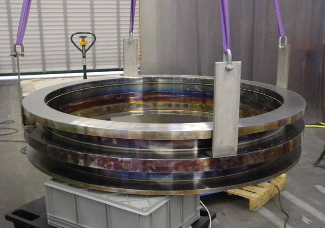
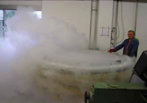

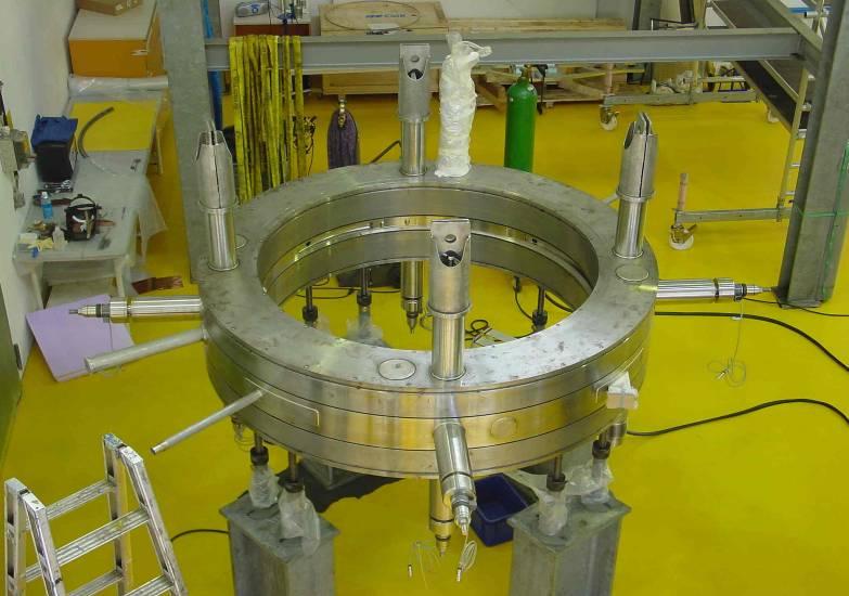
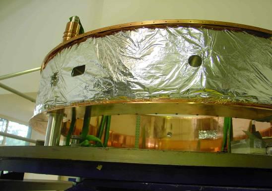
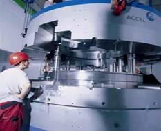
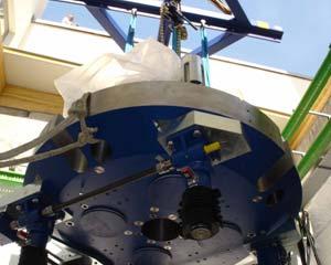
12 Manufacturing: cold mass and coils

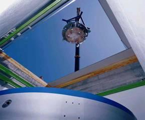
13 Mounting of cryostat into lower yoke

14 First successful Ramping of PSI Cyclotron Magnet, 12/2003
 : 0.4-0.6 W KVI (Beijers, Brandenburg) : 0.3 W ACCEL : 0.")

15 Performance Cryogenic System / cooling capacity Calc. of heat load in cold mass per 100 na stopped: PSI (Atchison) : W KVI (Beijers, Brandenburg) : 0.3 W ACCEL : 0.58 W Δ = na Calculation of heat load induced by neutrons produced by dumping protons into beam probe PHeater=3.7 W measured of heat load 0.36 W / 100 na stopped beam plhe=1040 mbar or 1.8 W / 500 na Acceptance test performed with only 3 of 4 cold heads in operation. comfortable margin

16 Factory Tests: Cryogenics Design current (160A) exceeded without any quench Large amount (> 4 W) of redundant cooling power Superconductor with high stability margin: quench heater power > 4 W Proven conservative cryogenic design
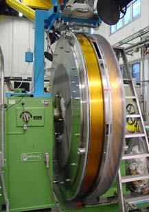
17 Commissioning / Verification Isochronism: Smith Garren measurement Smith-Garren: Variation of main coil current Goal: Verification of magnetic field shimming Verification of energy gain per turn Result: excellent agreement between phase curve derived from measured field maps and Smith- Garren measurement


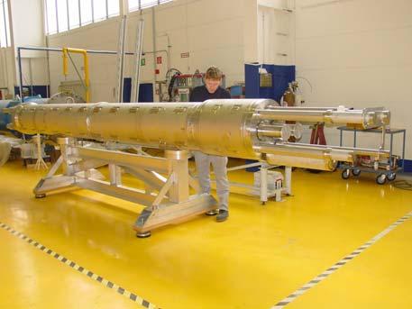
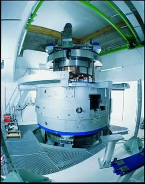
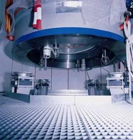
18 The 250 MeV Proton Cyclotron at ACCEL for cryogenic and magnetic factory tests magnetic measurement arm with search coil
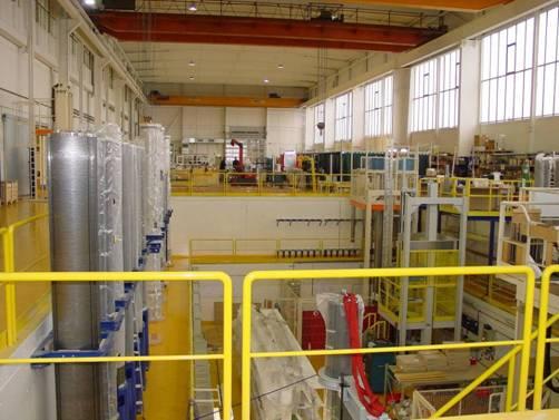
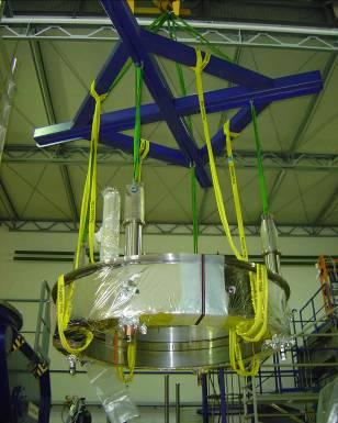
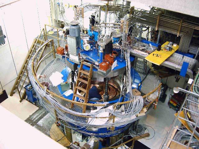
19 Installation of the Cyclotron at RPTC


20 Commissioning Status PSI Cyclotron Sept. 04 (~ Tokyo-Conference) Courtesy of PSI
21 System Overview Time line PSI - Project learning curve Δt=10 months Δt=2 months Δt=2 ½ weeks Commissioning start at RPTC: Feb. 05 first beam at RPTC: Apr 19th Contract RPTC: spring 2002 contract Apr. 01 Start commissioning Cyclotron Conferences: East Lansing `01 Tokyo`04 Giardini Naxos `07 Dec. 04 first beam April1st, 05 Dec. 05 Mar. 06 Oct. 06 Feb. 07 acceptance test phase end of test phase Start of PROSCAN Integration 1st Patient Now: cyclotron routinely run by operators


 ACCEL")
 separate")
22 Design: RF-Structures RF-Design Started with simple models for estimations/rough and fast optimization steps (e.g. acc. gap) NSCL Detailed 3D-Models of one sector (Microwave Studio, O(10 6 ) nodes) Simple 3D-Models full geometry (Microwave Studio) ACCEL Detailed full 3D-Model (using 3D-CAD data, Omega 3P) separate talk 18B3, H. Fitze, PSI PSI

23 Cyclotron Inner Region E-Fields, First proton turns Extensive 3D-Computations performed to optimize pattern of electical fields

, extensive use of acurate and detailed modelling paid off: No problem with high electric fields in the inner")
24 Design: RF-Structures Central Region: Started with electrostatic and rough model (Relax 3D) Refinement of electrostatic design with TOSCA 3D Exchange of data between 3D-CAD and TOSCA for iterations, goals: Optimizing focusing, minimize electric fields, etc. 3D-CAD 3D E-Static TOSCA Model Good agreement: calculated and measured mode separation, Needed RF power = 110 kw (120 kw deduced from calculations + experience), extensive use of acurate and detailed modelling paid off: No problem with high electric fields in the inner region (200 kv/cm)
25 RF System Commissioning Good agreement: calculated and measured mode separation Needed power 110 kw (120 kw deduced from calculations + experience) extensive use of acurate and detailed modelling paid off: No problem with high electric fields in the inner region (200 kv/cm) number of spark events within specs talk M. Schippers (MOXCR04,Cyclotron Conf. 2007) Contact fingers in RF amplifier and Dee 3 exchanged
 at 72.8 MHz Sufficient distance to mode 2?")

26 Medical Cyclotron Simulation Results Mode Separation: Desired mode is mode1 (push-pull mode) at 72.8 MHz Sufficient distance to mode 2? Excitation of higher order modes by harmonics? Tuning Resonance tuning: moving all 8 shorting plates identical Field balance tuning: moving each shorting plate individually slide 26 CST UGM 2007 /

27 Medical Cyclotron Simulation Results Gap-Voltage distribution Voltage minimum at stem position Results used for beam dynamic calculations Design of Contact Springs Calculation of maximum current at contact spring position Verification of contact spring design voltage [kv] Dee 1 entry Dee 1 exit radius [mm] slide 27 CST UGM 2007 /


")
28 Fitted Dee Voltage (kv) RF System Commissioning Spread in DEE voltages reduced from Δ=20kV to Δ=2kV with a X-ray detector DEE 1 DEE 2 DEE 3 DEE 4 number of RF trips strongly reduced problem with contact fingers eliminated BEFORE 82 Δ=2kV RF Power (kw) AFTER


29 Commissioning / RF System Model is fitted to determine Dee voltage Online fitting side development Small low resolution X-ray detector Collimation from iron Easy calibration and exchange
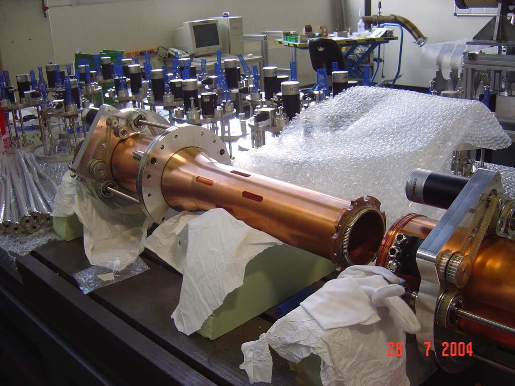
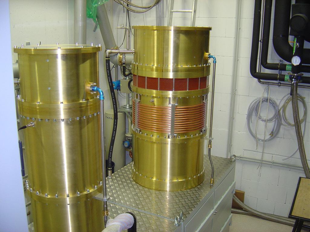
30 RF-Stems, RF-Amplifier
31 Animation of Cyclotron Acceleration
32 System Performance Overview Purpose: medical cyclotron serving as the source for proton therapy Design Goals: High reliability Low activation Easy maintenance Suitable for advanced scanning techniques Fast morning start-up Easy to use
33 First Steps: Beam Centering and Beam Control
 and RPTC Now: clear evidence that")

34 Performance Stability := ½ (I Max I Min) / < I > Ion Source Beam Current Measurements at RPTC: before: stability typically 30% acceptable beam quality for simple raster scanning at PSI (Gantry 1) and RPTC Now: clear evidence that ion source is capable of providing adequate beam quality for 2D-fast scanning Recently: After applying changes to the geometry of plasma chamber Fulfills requirements for PSI - Gantry 2 and RPTC after: stability: better 10%, reproducible
35 Commissioning / Beam Optimization Beam centering Bad Centering Beam current (na) Measured beam current Measured turn separation 4 Turn separation (mm) beam measured with shadow finger probe on platform in inner region (commissioning probe) Cyclotron radius (mm) 2 0 centering optimized with magnetic Trim Rods Beam current (na) 3 2 Good Centering Measured beam current Measured turn separation 4 Turn separation (mm) Cyclotron radius (mm)


36 Intensity modulation 1. Ion Source For slow variations 2. Vertical deflector plates Variations up to 10kHz First results: Saw-tooth voltage Vertical beam profile visible Vertical position on external monitor is stable


37 Intensity control - Max intensity set by: Ion source + phase slits Roles of deflector plate: - decrease drift of intensity - set requested intensity within 5% Febr. 2007: start program to reach spec=> best:σ =3 % (see poster) Courtesy of M. Schippers, PSI


")


38 Diagnostics Radial probe viewer Commissioning Radial probe integral head Foils Profile monitors Beam Current (na) Radius (mm) + Special developments: Commissioning probe probe head X-ray detector Phase probe (automation) platform platform

 Beam intensity On/off by means of Vertical deflector in")
39 Vertical deflector in cycl. Center -beam on/off Beam on/off and stability Necessary for fast dynamic scanning (Gantry-2) Acceptance tests: repetition rate 1 khz beam off < 50 μsec intensity stability σ<5% (for Gantry-1 and München: ) Beam intensity On/off by means of Vertical deflector in center 40 μs ms time (ms)

40 Extraction from cyclotron 80% Courtesy of M. Schippers, PSI Electrostatic extraction elements (ACCEL / Varian)
41 Commissioning / beam optimization Extraction efficiency one of the most important parameters / design goals low activation allows efficient maintenance high up-time specified: > 80% difficult to measure M. Schippers (MOXCR04) Now: routine at PSI: 85%, tuned by operators at RPTC: 80%, tuned by operators not being explored further

 : on pole, closed cap: mid plane, open pole cap: 400 μsv/h (40")
42 >80% extraction efficiency: Low dose to service staff inside cyclotron Mid plane, open cap 24 h after beam off, June 2007 (extracted beam integral 72 μa.h) : on pole, closed cap: mid plane, open pole cap: 400 μsv/h (40 mrem/h) 250 μsv/h (25 mrem/h) Courtesy of M. Schippers, PSI
43 Extraction efficiency Rextr R=30cm 140 probe signal (%) Simulations of probe efficiency Measurement of current on probe: Extr eff= 80.6% Radius in cyclotron (cm) Electrostatic extraction elements R=30 cm: 100% Routinely: 80-83%
44 Performance Automation / daily work: switch on the beam from overnight shutdown: - two button process on control system panel beam within 8 min - isochronism is maintained by an automated phase control loop beam within spec and machine ready for daily QA-checks within 10 min ( = additional 2 min ) perform calibration (beam current) and daily QA checks
45 Automation: Performance Transition Overnight Shutdown -> Beam On IMag = 158A IMag = f(irontemp) IMag = f(phase) PRF = 85kW UVD = 3.5kV H2-flow = 1.4sccm PRF = 110kW UEDx = 50kV ISarc = 250mA Ibeam within spec t=0min t=1min t=6min t=8min t=10min calibration phase measurement 2 automatic phase control loop no operators routinely required (PSI specification): very close
46 Maintenance Performance relevant maintenance operations so far for internal components since 2005: Ion Source: every 2 weeks, exchange/cleaning of chimney and cathode, breaking of cyclotron vacuum not necessary RF-Window (cleaning) Jacking-System of the pole cap (greasing) vertical deflector (exchange, RPTC only) Regular maintenance of cold heads and shield coolers extraction deflectors: one set of deflectors and HV feed throughs installed for more than one year at PSI, similar at RPTC
47 Introduction ACCEL History Why Particle Therapy? System Technology Contents Cyclotron versus Synchrotron Magnet Technology: Advantage of Superconductivity The ACCEL 250 MeV Cyclotron - Overview Performance Ion Source (Animation!) RF-System Activation / Maintenance Automation / daily work Reliability Proton Therapy Facility and Application Scanning Requirements, Workflow, (New) Layouts, Conclusions
 for the PSI PROSCAN project")

 Munich, Germany As part of the delivery of complete proton therapy system")
48 System Overview Varian/ACCEL Cyclotron installed at: Paul Scherrer Institut (PSI), Villigen, Switzerland dedicated cyclotron (COMET) for the PSI PROSCAN project intensification of R&D on proton therapy like intensity modulated proton therapy (IMPT) faster treatment, repainting of large volumes, etc. Cyclotron bunker at PSI, Villigen (courtesy of PSI) Rinecker Proton Therapy Center (RPTC) Munich, Germany As part of the delivery of complete proton therapy system identical to the PSI cyclotron Cyclotron bunker at RPTC, Munich

49 Proton Therapy Facilities beam/patient paths textfeld

50 Proton Therapy Facility RPTC, Munich I. S.C. cyclotron III. Gantry Rooms Eye Treatment Room II. Energy Selection System/ Beam Transfer Line ~90 m ~15 m


51 Beam-energy adjustment Degrader unit Q Q Q Steerer (Kicker) Carbon wedge degrader MeV 5 mm ΔRange in 50 ms
 vertical (π mm mrad)")
52 Energy verification Specified: MeV PSI: MeV RPTC: MeV Commissioning / Verification Emittance verification horizontal (π mm mrad) vertical (π mm mrad) Specified (95% of particles): PSI:

53 Energy measurement Ion chamber in water tank to measure proton range Range in water => E=250.4(1) MeV

 Gantry for")


54 Product Offering Turn Key Proton Therapy Facility SC Cyclotron Beam Transfer Line (Energy Selection Section w/ Degrader) Gantry for 360 Irradiation Scanning Nozzle Patient Couch Patient Position Verification Integrated Software Package ( TP, TCS, PIS, etc.) Building Interfacing
55 Conclusions PSI cyclotron has been commissioned successfully and has been accepted design and calculations were verified design goals fulfilled, in particular performance and reliability fulfill high demands on medical devices PSI cyclotron is fully operational, patient treatment has started RPTC patient treatment has started March 09
56 Perspectives: Industrialization of Fabrication of PT- Equipment, especially of sc Cyclotrons! Expansion to Ion Therapy? Expansion into smaller Synchro- Cyclotrons?
57 Thank you for your attention!
Recent developments in cyclotrons for proton therapy at IBA
 Recent developments in cyclotrons for proton therapy at IBA Yves Jongen. Founder & CRO IBA sa We Protect, Enhance and Save Lives. A typical PT center 30-55 millions for equipment 45-100 millions for the
THE IBA SUPERCONDUCTING SYNCHROCYCLOTRON PROJECT S2C2
 THE IBA SUPERCONDUCTING SYNCHROCYCLOTRON PROJECT S2C2 W. Kleeven, M. Abs, E. Forton, S. Henrotin, Y. Jongen, V. Nuttens, Y. Paradis, E. Pearson, S. Quets, J. Van de Walle, P. Verbruggen, S. Zaremba, IBA,
DOSE DELIVERY SYSTEM OF THE VARIAN PROBEAM SYSTEM WITH CONTINUOUS BEAM
 DOSE DELIVERY SYSTEM OF THE VARIAN PROBEAM SYSTEM WITH CONTINUOUS BEAM EUCARD 2 WORKSHOP ON INNOVATIVE DELIVERY SYSTEMS IN PARTICLE THERAPY TORINO, 23 25 FEB 2017 VARIAN PARTICLE THERAPY HOLGER GÖBEL MANGER
III. Proton-therapytherapy. Rome SB - 3/5 1
 Outline Introduction: an historical review I Applications in medical diagnostics Particle accelerators for medicine Applications in conventional radiation therapy II III IV Hadrontherapy, the frontier
Particle Beam Production - A Synchrotron-Based System - Prof. Dr. Thomas Haberer Scientific-technical Director Heidelberg Iontherapy Center
 Particle Beam Production - A Synchrotron-Based System - Prof. Dr. Thomas Haberer Scientific-technical Director Heidelberg Iontherapy Center Outline Situation/Rationale Requirements Synchrotron choice Functions
Cyclotron Institute upgrade project. H. L. Clark, F. Abegglen, G. Chubarian, G. Derrig, G. Kim, D. May, B. Roeder and G. Tabacaru
 Cyclotron Institute upgrade project H. L. Clark, F. Abegglen, G. Chubarian, G. Derrig, G. Kim, D. May, B. Roeder and G. Tabacaru On January 3, 2005 the Cyclotron Institute Upgrade Project (CIUP) began
PRESENT STATUS OF J-PARC
 PRESENT STATUS OF J-PARC # F. Naito, KEK, Tsukuba, Japan Abstract Japan Proton Accelerator Research Complex (J-PARC) is the scientific facility with the high-intensity proton accelerator aiming to realize
Experience with the Cornell ERL Injector SRF Cryomodule during High Beam Current Operation
 Experience with the Cornell ERL Injector SRF Cryomodule during High Beam Current Operation Matthias Liepe Assistant Professor of Physics Cornell University Experience with the Cornell ERL Injector SRF
Implementing a Proton Beam Scanning System within an Operating Clinical Facility
 Implementing a Proton Beam Scanning System within an Operating Clinical Facility Ben Clasie Many thanks to Hassan Bentefour, Hanne Kooy, and Jay Flanz for their help preparing this presentation 1 Francis
The ESS Accelerator. For Norwegian Industry and Research. Oslo, 24 Sept Håkan Danared Deputy Head Accelerator Division Group Leader Beam Physics
 The ESS Accelerator For Norwegian Industry and Research Oslo, 24 Sept 2013 Håkan Danared Deputy Head Accelerator Division Group Leader Beam Physics The Hadron Intensity Frontier Courtesy of M. Seidel (PSI)
NEW CYCLOTRON DEVELOPMENTS AT IBA
 NEW CYCLOTRON DEVELOPMENTS AT Y. Jongen, W. Kleeven and S.Zaremba, Chemin du Cyclotron 3, B-1348 Louvain-la-Neuve, Belgium Abstract This paper describes some recent cyclotron developments done at - Ion
Linac 4 Instrumentation K.Hanke CERN
 Linac 4 Instrumentation K.Hanke CERN CERN Linac 4 PS2 (2016?) SPL (2015?) Linac4 (2012) Linac4 will first inject into the PSB and then can be the first element of a new LHC injector chain. It will increase
LHC Beam Instrumentation Further Discussion
 LHC Beam Instrumentation Further Discussion LHC Machine Advisory Committee 9 th December 2005 Rhodri Jones (CERN AB/BDI) Possible Discussion Topics Open Questions Tune measurement base band tune & 50Hz
Hadron Therapy Technologies
 Hadron Therapy Technologies S. Peggs, BNL & ESS-S Bevalac 1950-1993 Many figures courtesy of Jay Flanz 1 Consumer demand 1 in 3 Europeans will confront some form of cancer in their lifetime. Cancer is
A HIGH POWER LONG PULSE HIGH EFFICIENCY MULTI BEAM KLYSTRON
 A HIGH POWER LONG PULSE HIGH EFFICIENCY MULTI BEAM KLYSTRON A.Beunas and G. Faillon Thales Electron Devices, Vélizy, France S. Choroba DESY, Hamburg, Germany Abstract THALES ELECTRON DEVICES has developed
OPERATIONAL EXPERIENCE AT J-PARC
 OPERATIONAL EXPERIENCE AT J-PARC Hideaki Hotchi, ) for J-PARC commissioning team ), 2), ) Japan Atomic Energy Agency (JAEA), Tokai, Naka, Ibaraki, 39-95 Japan, 2) High Energy Accelerator Research Organization
The Construction Status of CSNS Linac
 The Construction Status of CSNS Linac Sheng Wang Dongguan branch, Institute of High Energy Physics, CAS Sep.2, 2014, Geneva Outline The introduction to CSNS accelerators The commissoning of ion source
2 Work Package and Work Unit descriptions. 2.8 WP8: RF Systems (R. Ruber, Uppsala)
") 2 Work Package and Work Unit descriptions 2.8 WP8: RF Systems (R. Ruber, Uppsala) The RF systems work package (WP) addresses the design and development of the RF power generation, control and distribution
2 Work Package and Work Unit descriptions 2.8 WP8: RF Systems (R. Ruber, Uppsala) The RF systems work package (WP) addresses the design and development of the RF power generation, control and distribution
Diamond RF Status (RF Activities at Daresbury) Mike Dykes
 Mike Dykes") Diamond RF Status (RF Activities at Daresbury) Mike Dykes ASTeC What is it? What does it do? Diamond Status Linac Booster RF Storage Ring RF Summary Content ASTeC ASTeC was formed in 2001 as a centre of
Diamond RF Status (RF Activities at Daresbury) Mike Dykes ASTeC What is it? What does it do? Diamond Status Linac Booster RF Storage Ring RF Summary Content ASTeC ASTeC was formed in 2001 as a centre of
Upgrading LHC Luminosity
 1 Upgrading LHC Luminosity 2 Luminosity (cm -2 s -1 ) Present (2011) ~2 x10 33 Beam intensity @ injection (*) Nominal (2015?) 1 x 10 34 1.1 x10 11 Upgraded (2021?) ~5 x10 34 ~2.4 x10 11 (*) protons per
Detailed Design Report
 Detailed Design Report Chapter 4 MAX IV Injector 4.6. Acceleration MAX IV Facility CHAPTER 4.6. ACCELERATION 1(10) 4.6. Acceleration 4.6. Acceleration...2 4.6.1. RF Units... 2 4.6.2. Accelerator Units...
Beam Loss Detection for MPS at FRIB
 Beam Loss Detection for MPS at FRIB Zhengzheng Liu Beam Diagnostics Physicist This material is based upon work supported by the U.S. Department of Energy Office of Science under Cooperative Agreement DE-SC0000661.
Commissioning the TAMUTRAP RFQ cooler/buncher. E. Bennett, R. Burch, B. Fenker, M. Mehlman, D. Melconian, and P.D. Shidling
 Commissioning the TAMUTRAP RFQ cooler/buncher E. Bennett, R. Burch, B. Fenker, M. Mehlman, D. Melconian, and P.D. Shidling In order to efficiently load ions into a Penning trap, the ion beam should be
Pulsed Klystrons for Next Generation Neutron Sources Edward L. Eisen - CPI, Inc. Palo Alto, CA, USA
 Pulsed Klystrons for Next Generation Neutron Sources Edward L. Eisen - CPI, Inc. Palo Alto, CA, USA Abstract The U.S. Department of Energy (DOE) Office of Science has funded the construction of a new accelerator-based
Therapy Control and Patient Safety for Proton Therapy
 Proceedings of the CAS-CERN Accelerator School: Accelerators for Medical Applications, Vösendorf, Austria, 26 May 5 June 2015, edited by R. Bailey, CERN Yellow Reports: School Proceedings, Vol. 1/2017,
4.4 Injector Linear Accelerator
 4.4 Injector Linear Accelerator 100 MeV S-band linear accelerator based on the components already built for the S-Band Linear Collider Test Facility at DESY [1, 2] will be used as an injector for the CANDLE
Commissioning of Accelerators. Dr. Marc Munoz (with the help of R. Miyamoto, C. Plostinar and M. Eshraqi)
") Commissioning of Accelerators Dr. Marc Munoz (with the help of R. Miyamoto, C. Plostinar and M. Eshraqi) www.europeanspallationsource.se 6 July, 2017 Contents General points Definition of Commissioning
Commissioning of Accelerators Dr. Marc Munoz (with the help of R. Miyamoto, C. Plostinar and M. Eshraqi) www.europeanspallationsource.se 6 July, 2017 Contents General points Definition of Commissioning
ESS: The Machine. Bucharest, 24 April Håkan Danared Deputy Head Accelerator Division. H. Danared Industry & Partner Days Bucharest Page 1
 ESS: The Machine Bucharest, 24 April 2014 Håkan Danared Deputy Head Accelerator Division H. Danared Industry & Partner Days Bucharest Page 1 2025 ESS construction complete 2009 Decision: ESS will be built
Performance of a DC GaAs photocathode gun for the Jefferson lab FEL
 Nuclear Instruments and Methods in Physics Research A 475 (2001) 549 553 Performance of a DC GaAs photocathode gun for the Jefferson lab FEL T. Siggins a, *, C. Sinclair a, C. Bohn b, D. Bullard a, D.
EPJ Web of Conferences 95,
 EPJ Web of Conferences 95, 04012 (2015) DOI: 10.1051/ epjconf/ 20159504012 C Owned by the authors, published by EDP Sciences, 2015 The ELENA (Extra Low Energy Antiproton) project is a small size (30.4
The PEFP 20-MeV Proton Linear Accelerator
 Journal of the Korean Physical Society, Vol. 52, No. 3, March 2008, pp. 721726 Review Articles The PEFP 20-MeV Proton Linear Accelerator Y. S. Cho, H. J. Kwon, J. H. Jang, H. S. Kim, K. T. Seol, D. I.
Digital BPMs and Orbit Feedback Systems
 Digital BPMs and Orbit Feedback Systems, M. Böge, M. Dehler, B. Keil, P. Pollet, V. Schlott Outline stability requirements at SLS storage ring digital beam position monitors (DBPM) SLS global fast orbit
Proton Engineering Frontier Project
 Proton Engineering Frontier Project OECD Nuclear Energy Agency Fifth International Workshop on the Utilisation and Reliability of High Power Proton Accelerators (HPPA5) (6-9 May 2007, Mol, Belgium) Yong-Sub
Transverse collimation with the Superconducting ECR ion source SuSI at the Coupled Cyclotron Facility (CCF)
") Transverse collimation with the Superconducting ECR ion source SuSI at the Coupled Cyclotron Facility (CCF) Outline CCF / Motivations to build SuSI Features of SuSI Intensity Performances Installation
Transverse collimation with the Superconducting ECR ion source SuSI at the Coupled Cyclotron Facility (CCF) Outline CCF / Motivations to build SuSI Features of SuSI Intensity Performances Installation
G. Pittá(*), S. Braccini TERA Foundation, Novara, Italy (*) Corresponding author.
, S. Braccini TERA Foundation, Novara, Italy (*) Corresponding author.") Frascati Physics Series Vol. VVVVVV (xxxx), pp. 000-000 XX Conference Location, Date-start - Date-end, Year MATRIX: AN INNOVATIVE PIXEL IONIZATION CHAMBER FOR ON-LINE BEAM MONITORING IN HADRONTHERAPY G.
Frascati Physics Series Vol. VVVVVV (xxxx), pp. 000-000 XX Conference Location, Date-start - Date-end, Year MATRIX: AN INNOVATIVE PIXEL IONIZATION CHAMBER FOR ON-LINE BEAM MONITORING IN HADRONTHERAPY G.
Cyclotron Institute upgrade project. H. L. Clark, F. Abegglen, G. Chubarian, G. Derrig, G. Kim, D. May, and G. Tabacaru
 Cyclotron Institute upgrade project H. L. Clark, F. Abegglen, G. Chubarian, G. Derrig, G. Kim, D. May, and G. Tabacaru On January 3, 2005 the Cyclotron Institute Upgrade Project (CIUP) began with the approval
3 cerl. 3-1 cerl Overview. 3-2 High-brightness DC Photocathode Gun and Gun Test Beamline
 3 cerl 3-1 cerl Overview As described before, the aim of the cerl in the R&D program includes the development of critical components for the ERL, as well as the construction of a test accelerator. The
LLRF at SSRF. Yubin Zhao
 LLRF at SSRF Yubin Zhao 2017.10.16 contents SSRF RF operation status Proton therapy LLRF Third harmonic cavity LLRF Three LINAC LLRF Hard X FEL LLRF (future project ) Trip statistics of RF system Trip
DEVELOPMENT OF A 10 MW SHEET BEAM KLYSTRON FOR THE ILC*
 DEVELOPMENT OF A 10 MW SHEET BEAM KLYSTRON FOR THE ILC* D. Sprehn, E. Jongewaard, A. Haase, A. Jensen, D. Martin, SLAC National Accelerator Laboratory, Menlo Park, CA 94020, U.S.A. A. Burke, SAIC, San
LIGHT PROTON THERAPY PROJECT
 17 th of MAY 2018 LIGHT PROTON THERAPY PROJECT Yevgeniy Ivanisenko on behalf of ADAM team FORM-01040-A AVO-ADAM Advanced Oncotherapy (AVO) is a public company ADAM is R&D center of AVO ~ 100 employees
TECHNICAL SPECIFICATION Multi-beam S-band Klystron type BT267
 TECHNICAL SPECIFICATION Multi-beam S-band Klystron type BT267 The company was created for the development and manufacture of precision microwave vacuum-electron-tube devices (VETD). The main product areas
45 MW, 22.8 GHz Second-Harmonic Multiplier for High-Gradient Tests*
 US High Gradient Research Collaboration Workshop. SLAC, May 23-25, 2007 45 MW, 22.8 GHz Second-Harmonic Multiplier for High-Gradient Tests* V.P. Yakovlev 1, S.Yu. Kazakov 1,2, and J.L. Hirshfield 1,3 1
STATUS OF THE SWISSFEL C-BAND LINEAR ACCELERATOR
 Proceedings of FEL213, New York, NY, USA STATUS OF THE SWISSFEL C-BAND LINEAR ACCELERATOR F. Loehl, J. Alex, H. Blumer, M. Bopp, H. Braun, A. Citterio, U. Ellenberger, H. Fitze, H. Joehri, T. Kleeb, L.
A NOVEL GANTRY FOR PROTON THERAPY AT THE PAUL SCHERRER INSTITUTE
 A NOVEL GANTRY FOR PROTON THERAPY AT THE PAUL SCHERRER INSTITUTE E. Pedroni, T. Böhringer, A. Coray, G. Goitein, M. Grossmann, A. Lomax, S. Lin, M. Jermann Paul Scherrer Institute, CH-5232 Villigen PSI,
RF considerations for SwissFEL
 RF considerations for H. Fitze in behalf of the PSI RF group Workshop on Compact X-Ray Free Electron Lasers 19.-21. July 2010, Shanghai Agenda Introduction RF-Gun Development C-band development Summary
Next Linear Collider. The 8-Pack Project. 8-Pack Project. Four 50 MW XL4 X-band klystrons installed on the 8-Pack
 The Four 50 MW XL4 X-band klystrons installed on the 8-Pack The Demonstrate an NLC power source Two Phases: 8-Pack Phase-1 (current): Multi-moded SLED II power compression Produce NLC baseline power: 475
Summary of the 1 st Beam Line Review Meeting Injector ( )
") Summary of the 1 st Beam Line Review Meeting Injector (23.10.2006) 15.11.2006 Review the status of: beam dynamics understanding and simulations completeness of beam line description conceptual design of
Summary of the 1 st Beam Line Review Meeting Injector (23.10.2006) 15.11.2006 Review the status of: beam dynamics understanding and simulations completeness of beam line description conceptual design of
Current status of XFEL/SPring-8 project and SCSS test accelerator
 Current status of XFEL/SPring-8 project and SCSS test accelerator Takahiro Inagaki for XFEL project in SPring-8 inagaki@spring8.or.jp Outline (1) Introduction (2) Key technology for compactness (3) Key
Design of the linear accelerator for the MYRRHA project
 MYRRHA Multipurpose hybrid Research Reactor for High-tech Applications Design of the linear accelerator for the MYRRHA project Roberto Salemme ADT - Outline What is MYRRHA? MYRRHA accelerator: requirements
100 MeV H - CYCLOTRON DEVELOPMENT AND 800 MeV PROTON CYCLOTRON PROPOSAL*
 Proceedings of Cyclotrons2016, Zurich, Switzerland TUC01 100 MeV H - CYCLOTRON DEVELOPMENT AND 800 MeV PROTON CYCLOTRON PROPOSAL* Tianjue Zhang and Jianjun Yang, China Institute of Atomic Energy, Beijing,
The FAIR plinac RF Systems
 The FAIR plinac RF Systems Libera Workshop Sep. 2011 Gerald Schreiber Gerald Schreiber, GSI RF Department 2 (1) Overview GSI / FAIR (2) FAIR Proton Linear Accelerator "plinac" (3) plinac RF Systems (4)
RF plans for ESS. Morten Jensen. ESLS-RF 2013 Berlin
 RF plans for ESS Morten Jensen ESLS-RF 2013 Berlin Overview The European Spallation Source (ESS) will house the most powerful proton linac ever built. The average beam power will be 5 MW which is five
Development of New Carbon Therapy Facility and Future Plan of HIMAC
 Development of New Carbon Therapy Facility and Future Plan of Koji Noda Research Center for Charged Particle Therapy National Institute of Radiological Sciences 1. Introduction Contents 2. New Carbon-Therapy
Design, Fabrication and Testing of Gun-Collector Test Module for 6 MW Peak, 24 kw Average Power, S-Band Klystron
 Available online www.ejaet.com European Journal of Advances in Engineering and Technology, 2014, 1(1): 11-15 Research Article ISSN: 2394-658X Design, Fabrication and Testing of Gun-Collector Test Module
Oak Ridge Spallation Neutron Source Proton Power Upgrade Project and Second Target Station Project
 Oak Ridge Spallation Neutron Source Proton Power Upgrade Project and Second Target Station Project Workshop on the future and next generation capabilities of accelerator driven neutron and muon sources
Status of SOLARIS Arkadiusz Kisiel
 Status of SOLARIS Arkadiusz Kisiel Solaris National Synchrotron Light Source Jagiellonian University Czerwone Maki 98 30-392 Kraków www.synchrotron.uj.edu.pl Arkadiusz.Kisiel@uj.edu.pl On behalf of SOLARIS
Tutorial: Trak design of an electron injector for a coupled-cavity linear accelerator
 Tutorial: Trak design of an electron injector for a coupled-cavity linear accelerator Stanley Humphries, Copyright 2012 Field Precision PO Box 13595, Albuquerque, NM 87192 U.S.A. Telephone: +1-505-220-3975
Proceedings of the 1997 Workshop on RF Superconductivity, Abano Terme (Padova), Italy
, Italy") BEAM RELATED THERMAL LOSSES ON THE CRYOGENIC AND VACUUM SYSTEMS OF LEP G. Cavallari, Ph. Gayet, G. Geschonke, D. Kaiser, J.M. Jimenez CERN, 111 GENEVA 3 (Switzerland) Abstract The LEP Collider was operated
BEAM RELATED THERMAL LOSSES ON THE CRYOGENIC AND VACUUM SYSTEMS OF LEP G. Cavallari, Ph. Gayet, G. Geschonke, D. Kaiser, J.M. Jimenez CERN, 111 GENEVA 3 (Switzerland) Abstract The LEP Collider was operated
The field cage for a large TPC prototype
 EUDET The field cage for a large TPC prototype T.Behnke, L. Hallermann, P. Schade, R. Diener December 7, 2006 Abstract Within the EUDET Programme, the FLC TPC Group at DESY in collaboration with the Department
P. Emma, et al. LCLS Operations Lectures
 P. Emma, et al. LCLS Operations Lectures LCLS 1 LCLS Accelerator Schematic 6 MeV 135 MeV 250 MeV σ z 0.83 mm σ z 0.83 mm σ z 0.19 mm σ δ 0.05 % σ δ 0.10 % σ δ 1.6 % Linac-0 L =6 m rf gun L0-a,b Linac-1
CMS Upgrade Activities
 CMS Upgrade Activities G. Eckerlin DESY WA, 1. Feb. 2011 CMS @ LHC CMS Upgrade Phase I CMS Upgrade Phase II Infrastructure Conclusion DESY-WA, 1. Feb. 2011 G. Eckerlin 1 The CMS Experiments at the LHC
30 GHz Power Production / Beam Line
 30 GHz Power Production / Beam Line Motivation & Requirements Layout Power mode operation vs. nominal parameters Beam optics Achieved performance Problems Beam phase switch for 30 GHz pulse compression
Towards an X-Band Power Source at CERN and a European Structure Test Facility
 Towards an X-Band Power Source at CERN and a European Structure Test Facility Erk Jensen and Gerry McMomagle CERN The X-Band Accelerating Structure Design and Test-Program Workshop Day 2: Structure Testing
Quality Assurance Implementation at the Roberts Proton Therapy Center. James McDonough 3 August 2013
 Quality Assurance Implementation at the Roberts Proton Therapy Center James McDonough 3 August 2013 1 Roberts Proton Therapy Center Machine configuration and layout 4 gantries, 1 fixed beam line, 1 research
Empirical Model For ESS Klystron Cathode Voltage
 Empirical Model For ESS Klystron Cathode Voltage Dave McGinnis 2 March 2012 Introduction There are 176 klystrons in the superconducting portion of ESS linac. The power range required spans a factor of
The LEP Superconducting RF System
 The LEP Superconducting RF System K. Hübner* for the LEP RF Group CERN The basic components and the layout of the LEP rf system for the year 2000 are presented. The superconducting system consisted of
RF Power Generation II
 RF Power Generation II Klystrons, Magnetrons and Gyrotrons Professor R.G. Carter Engineering Department, Lancaster University, U.K. and The Cockcroft Institute of Accelerator Science and Technology Scope
Investigation of Radio Frequency Breakdown in Fusion Experiments
 Investigation of Radio Frequency Breakdown in Fusion Experiments T.P. Graves, S.J. Wukitch, I.H. Hutchinson MIT Plasma Science and Fusion Center APS-DPP October 2003 Albuquerque, NM Outline Multipactor
ILC-LNF TECHNICAL NOTE
 IL-LNF EHNIAL NOE Divisione Acceleratori Frascati, July 4, 2006 Note: IL-LNF-001 RF SYSEM FOR HE IL DAMPING RINGS R. Boni, INFN-LNF, Frascati, Italy G. avallari, ERN, Geneva, Switzerland Introduction For
RF Solutions for Science.
 RF Solutions for Science www.thalesgroup.com State-of-the-art RF sources for your scientific needs High-power klystrons HIGH KLYSTRONS WITH RF LONG PULSE above 50 μs Thales has been one of the leading
New Filling Pattern for SLS-FEMTO
 SLS-TME-TA-2009-0317 July 14, 2009 New Filling Pattern for SLS-FEMTO Natalia Prado de Abreu, Paul Beaud, Gerhard Ingold and Andreas Streun Paul Scherrer Institut, CH-5232 Villigen PSI, Switzerland A new
Production of accelerators and accelerator components in industry
 Production of accelerators and accelerator components in industry Michael Pekeler RI Research Instruments GmbH Friedrich-Ebert-Str. 1 51429 Bergisch Gladbach 28.04.2009 Foundation of RI Research Instruments
ANKA Status Report. N.Smale, on behalf of all ANKA colleagues, Directors : A.-S. Müller, C Heske, T Baumbach.
 ANKA Status Report N.Smale, on behalf of all ANKA colleagues, Directors : A.-S. Müller, C Heske, T Baumbach. Institute for Synchrotron Radiation KIT - University of the State of Baden-Wuerttemberg and
Status of CTF3. G.Geschonke CERN, AB
 Status of CTF3 G.Geschonke CERN, AB CTF3 layout CTF3 - Test of Drive Beam Generation, Acceleration & RF Multiplication by a factor 10 Drive Beam Injector ~ 50 m 3.5 A - 2100 b of 2.33 nc 150 MeV - 1.4
Activities on FEL Development and Application at Kyoto University
 Activities on FEL Development and Application at Kyoto University China-Korea-Japan Joint Workshop on Electron / Photon Sources and Applications Dec. 2-3, 2010 @ SINAP, Shanghai Kai Masuda Inst. Advanced
CERN S PROTON SYNCHROTRON COMPLEX OPERATION TEAMS AND DIAGNOSTICS APPLICATIONS
 Marc Delrieux, CERN, BE/OP/PS CERN S PROTON SYNCHROTRON COMPLEX OPERATION TEAMS AND DIAGNOSTICS APPLICATIONS CERN s Proton Synchrotron (PS) complex How are we involved? Review of some diagnostics applications
Preparations for Installation, Testing and Commissioning based on Experience at CERN, SNS and Siemens
 Preparations for Installation, Testing and Commissioning based on Experience at CERN, SNS and Siemens Eugène Tanke FRIB / MSU ESS Seminar, Lund, 6 March 2013 Outline Project Goal for the Accelerator Path
Commissioning and Performance of the ATLAS Transition Radiation Tracker with High Energy Collisions at LHC
 Commissioning and Performance of the ATLAS Transition Radiation Tracker with High Energy Collisions at LHC 1 A L E J A N D R O A L O N S O L U N D U N I V E R S I T Y O N B E H A L F O F T H E A T L A
2008 JINST 3 S LHC Machine THE CERN LARGE HADRON COLLIDER: ACCELERATOR AND EXPERIMENTS. Lyndon Evans 1 and Philip Bryant (editors) 2
 2") PUBLISHED BY INSTITUTE OF PHYSICS PUBLISHING AND SISSA RECEIVED: January 14, 2007 REVISED: June 3, 2008 ACCEPTED: June 23, 2008 PUBLISHED: August 14, 2008 THE CERN LARGE HADRON COLLIDER: ACCELERATOR AND
PUBLISHED BY INSTITUTE OF PHYSICS PUBLISHING AND SISSA RECEIVED: January 14, 2007 REVISED: June 3, 2008 ACCEPTED: June 23, 2008 PUBLISHED: August 14, 2008 THE CERN LARGE HADRON COLLIDER: ACCELERATOR AND
5 Project Costs and Schedule
 93 5 Project Costs and Schedule 5.1 Overview The cost evaluation for the integrated version of the XFEL with 30 experiments and 35 GeV beam energy as described in the TDR-2001 yielded 673 million EUR for
Activities from Cyclotron facility at German Cancer Research Center (DKFZ), Heidelberg
, Heidelberg") 7/12/2016 Page 1 Activities from Cyclotron facility at German Cancer Research Center (DKFZ), Heidelberg 7/12/2016 Page 2 Biggest Transition in the last two years 7/12/2016 Page 3 A Brief Historical Overview
7/12/2016 Page 1 Activities from Cyclotron facility at German Cancer Research Center (DKFZ), Heidelberg 7/12/2016 Page 2 Biggest Transition in the last two years 7/12/2016 Page 3 A Brief Historical Overview
INSTRUMENT CATHODE-RAY TUBE
 Instrument cathode-ray tube D14-363GY/123 INSTRUMENT CATHODE-RAY TUBE mono accelerator 14 cm diagonal rectangular flat face internal graticule low power quick heating cathode high brightness, long-life
DIAGNOSTIC INSTRUMENTATION FOR MEDICAL ACCELERATOR FACILITIES
 DIAGNOSTIC INSTRUMENTATION FOR MEDICAL ACCELERATOR FACILITIES M. Schwickert, GSI, Darmstadt, Germany A. Peters, Hit GmbH, Heidelberg, Germany Abstract A number of accelerator facilities are presently emerging
North Damping Ring RF
 North Damping Ring RF North Damping Ring RF Outline Overview High Power RF HVPS Klystron & Klystron EPICS controls Cavities & Cavity Feedback SCP diagnostics & displays FACET-specific LLRF LLRF distribution
DIRECT DRIVE ROTARY TABLES SRT SERIES
 DIRECT DRIVE ROTARY TABLES SRT SERIES Key features: Direct drive Large center aperture Brushless motor design Precision bearing system Integrated position feedback Built-in thermal sensors ServoRing rotary
The FLASH objective: SASE between 60 and 13 nm
 Injector beam control studies winter 2006/07 talk from E. Vogel on work performed by W. Cichalewski, C. Gerth, W. Jalmuzna,W. Koprek, F. Löhl, D. Noelle, P. Pucyk, H. Schlarb, T. Traber, E. Vogel, FLASH
Hall-B Beamline Commissioning Plan for CLAS12
 Hall-B Beamline Commissioning Plan for CLAS12 Version 1.5 S. Stepanyan December 19, 2017 1 Introduction The beamline for CLAS12 utilizes the existing Hall-B beamline setup with a few modifications and
Experimental Results of the Coaxial Multipactor Experiment. T.P. Graves, B. LaBombard, S.J. Wukitch, I.H. Hutchinson PSFC-MIT
 Experimental Results of the Coaxial Multipactor Experiment T.P. Graves, B. LaBombard, S.J. Wukitch, I.H. Hutchinson PSFC-MIT Summary A multipactor discharge is a resonant condition for electrons in an
IOT OPERATIONAL EXPERIENCE ON ALICE AND EMMA AT DARESBURY LABORATORY
 IOT OPERATIONAL EXPERIENCE ON ALICE AND EMMA AT DARESBURY LABORATORY A. Wheelhouse ASTeC, STFC Daresbury Laboratory ESLS XVIII Workshop, ELLETRA 25 th 26 th November 2010 Contents Brief Description ALICE
18 GHz, 2.2 kw KLYSTRON GENERATOR GKP 24KP 18GHz WR62 3x400V
 18 GHz, 2.2 kw KLYSTRON GENERATOR GKP 24KP 18GHz WR62 3x400V With its characteristics of power stability whatever the load, very fast response time when pulsed (via external modulated signal), low ripple,
DISCLAIMER. Portions of this document may be illegible in electronic image products. Images are produced from the best available original document.
 DISCLAIMER This report was prepared as an account of work sponsored by an agency of the United States Government Neither the United States Government nor any agency thcreof nor any of their employees,
PBS Products from Pyramid
 PBS Products from Pyramid Pyramid was founded in 1986 and is an established supplier of instrument control systems for the medical, semiconductor, physics and biological research markets. The systems typically
TRIUMF CYCLOTRON MAIN MAGNET POWER SUPPLY REPLACEMENT
 Discovery, accelerated 1 TRIUMF CYCLOTRON MAIN MAGNET POWER SUPPLY REPLACEMENT Arthur Leung High Power DC Systems 2018-10-05 TRIUMF stands for TRI University Meson Facility Founded by University of British
Technology Challenges for SRF Guns as ERL Sources in View of Rossendorf work
 Technology Challenges for SRF Guns as ERL Sources in View of Rossendorf work, Hartmut Buettig, Pavel Evtushenko, Ulf Lehnert, Peter Michel, Karsten Moeller, Petr Murcek, Christof Schneider, Rico Schurig,
DELIVERY RECORD. Location: Ibaraki, Japan
 DELIVERY RECORD Client: Japan Atomic Energy Agency (JAEA) High Energy Accelerator Research Organization (KEK) Facility: J-PARC (Japan Proton Accelerator Research Complex) Location: Ibaraki, Japan 1 October
DESIGN OF 1.2-GEV SCL AS NEW INJECTOR FOR THE BNL AGS*
 DESIGN OF 1.2-GEV SCL AS NEW INJECTOR FOR THE BNL AGS* A. G. Ruggiero, J. Alessi, M. Harrison, M. Iarocci, T. Nehring, D. Raparia, T. Roser, J. Tuozzolo, W. Weng. Brookhaven National Laboratory, PO Box
High Power Cyclotrons
 Accelerator Reliability Workshop ESRF, Grenoble, 04-06.02.02 High Power Cyclotrons P.A.Schmelzbach 1. The PSI Proton Accelerator Facility 2. Failure Analysis 2000/2001 3. The weak Points 4. How to improve
RF Upgrades & Experience At JLab. Rick Nelson
 RF Upgrades & Experience At JLab Rick Nelson Outline Background: CEBAF / Jefferson Lab History, upgrade requirements & decisions Progress & problems along the way Present status Future directions & concerns
RUNNING EXPERIENCE OF FZD SRF PHOTOINJECTOR
 RUNNING EXPERIENCE OF FZD SRF PHOTOINJECTOR Rong Xiang On behalf of the BESSY-DESY-FZD-MBI collaboration and the ELBE team FEL 2009, Liverpool, United Kingdom, August 23 ~ 28, 2009 Outline Introduction
Program to improve the ion beam formation and transmission at JYFL
 Program to improve the ion beam formation and transmission at JYFL University of Jyväskylä, Department of Physics H. Koivisto, T. Ropponen, J. Ropponen, T. Koponen, M. Savonen, V. Toivanen, P. Heikkinen