GENESIS RADIO CALIBRATION PROCEDURES
|
|
|
- Helen Robinson
- 6 years ago
- Views:
Transcription
1 GENESIS RADIO CALIBRATION PROCEDURES covering all G59 models and GPA10 power amplifier
2 Si570 frequency adjustment

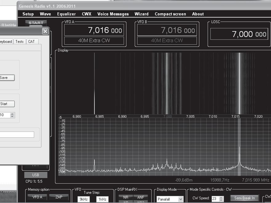
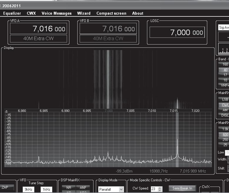
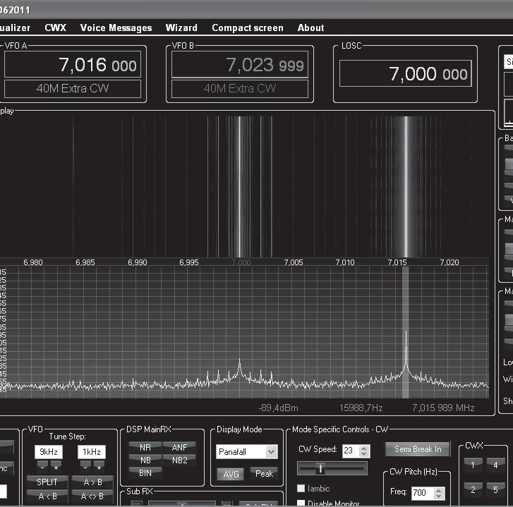
3 Si570 Frequency calibration This is a very straightforward and easy operation! 1- Set up your signal source (in this case a TS570D) in CW, at Mhz 2- Start your G59 and set your VFO A on same frequency - choose USB mode so you see your frequency divisions clearly in your panafall display. 3- In GSDR go to tab SET-UP>GENERAL>GENESIS CONFIG Look at the Genesis Si570 settings where you will find three frequency ranges. Calibration has to be performed on all three ranges. 4- Start the signal source and watch the signal appear on your G59. If your Si570 is off frequency (see screenshot 1), adjust the value in the box of the appropriate frequency range untill it is spot on (see screenshot 2) at Mhz. Each time you change that value you must press TEST to be valid. Si570 frequency off target correctly calibrated Si570 frequency
 does - should you not have a")

4 Si570 Frequency calibration using WWV as a signal source Of course you can all always use the WWV frequencies to calibrate the Si570 - I know Bruce (KF1Z) does - should you not have a second TX available. Screenshot below. Do you really want to have fun calibrating? Than choose Display mode: phase 2 and watch the circle slowing down the closer you get to the correct frequency!
5 RX image rejection
6 A- HARDWARE IMAGE REJECTION First start GSDR and select some frequency on 20 meter band. 20m band is recommended for optimum hardware image rejection results. Inject a good strong signal 15 to 25khz above or below the local oscillator (center ) frequency. See screenshot on page 4. Screenshots show 7 Mhz but procedure is identical. Signal should be at LEAST 70 to 80db or more above the RX noise floor. In GSDR go to Setup > General > Calibration WBIR box Press the (WBIR) STOP button. Adjust R23R on G59 board untill the IMAGE signal dips as low as you can get it. See screenshot on page 5. Your hardware IR is now set, leave R23R alone from now on. Then press the (WBIR) START button and proceed with the: B- SOFTWARE IMAGE REJECTION On to software... Now press RESET button in RX Image Reject Cal box. WAIT a few seconds (may take upto a minute even) after the image has completely disappeared into the noise. See screenshot on page 6. Then press SAVE. Important notice: Do the software calibration ( RESET/SAVE) on EVERY BAND, including the SWL bands if you use them. Repeat the software rejection procedure on each band to do the calibration properly. You can use a signal generator ( the built-in calibrator generator on MK2 and MK3 is there for this purpose). Or you can use a signal from a second transmitter ( proper dummy load or antenna of course).
7
8
9

10 Hardware RX IR using Winrad by VK2DX Connect the G59 to sound card. It s easy - one stereo cable, one connector on PCB, one antenna jack. It is NOT confusing and you can not make a mistake! Here is the photo of PCB in phase 5: Next step: download and run Winrad. Now you may ask why Winrad and not GSDR? Simple reason: Winrad is very easy to setup, and you only need to select a couple parameters: LO frequency, sound card input and sampling rate. Winrad is RX only software and you will not be confused with settings which are not required at this stage. But most importantly, there is no WBIR (automatic software Image rejection) in Winrad so the only rejection you can do is the one in G59 hardware. To adjust IR, you need a signal source. Signal source could be any HF transmitter. Any carrier will do, ideally a couple of watts from your big radio. - Let s say that you have set LO in winrad to MHz. - Set your signal source TX to and tune You will see big spike on winrad 10 KHz above LO. There will be another signal 10 KHz below LO (14.190). This is the unwanted image, the signal you want to reject. The adjustment is HARDWARE thing, matter of turning the trimmerpot on G59 board either clockwise or counterclockwise until that spike on goes as away. See At this stage you will have few possible outcomes: - image is rejected nicely, 40dB or more below main signal. This means all OK, your G59 is all good and you are ready to move on, - image is rejected only few db, 10 or 20 db or so. This means that something is wrong with your G59 hardware. Troubleshoot G59. - there is absolutely no difference between signal and image, and no matter what, they are same amplitude: you have mono input on soundcard, wrongly wired cables or soundcard issue. Fix it, then go back to hardware adjustment. Screenshot of correctly rejected RX image (-40 db)
11 TX image rejection includes modification for G59 beta & MK2
12


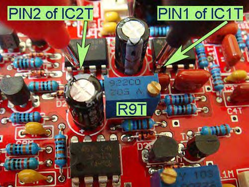
13 Hardware / Software TX IR using Winrad by ON4EZ This is done in a very similar way the RX IR is done BUT this time you are going to use Winrad as cheap spectrum analyser! This is how it is done: Connect the G59 to sound card. To adjust IR, you need a signal source. Now your G59 is the actual source. - Again,set LO in winrad to MHz. - Set your G59 VFOA to MHz and tune You will see your signal appear on Winrad 10 KHz above LO (in this case -3.3dB). There will be another signal 10 KHz below LO ( MHz). This is the unwanted image you want to reject. The adjustment we are doing now is HARDWARE, just turn the trimmerpot R9T on your G59 board either clockwise or counterclockwise until that spike on drops to the lowest possible value (G59 serial 017: value = db meaning a difference of more than - 60 db over the main signal). With that testrig the ideal setting of R9T came to 5K60 Ohms. (Further adjustment in GSDR yielded no extra rejection.) Further adjustment by band can be done in GSDR using the sliders and watch your signal image disappear even more (upto -15 db extra) if still possible. Screenshot of correctly rejected TX image in hardware (-61dB) your tools for additional software TX IR

14 I/Q balance, also called LO nulling or carrier suppression Adjustments: R9T is for TX image rejection. Trimmers R50T and R51T are for I/Q TX balance (carrier suppression). 1. Adjust image rejection with R9T. You should be able to achieve around 50dB of rejection on 40/30/20m band. The peak point is sharp and almost spot on 5K6. Don t worry about software adjustment at this stage. How much is a -50dB rejection? Well if you have no test equipment apart from a second receiver, then the G59 10mW signal transmitted into an external antenna should be S9 on your second receiver with a 1m piece of wire serving as a RX antenna. It could be more, but not significantly less. Let s say it is S9 (and you can make it to be S9 by adjusting the length of that piece of wire) then a -50dB signal at image frequency should be barely audible. If your main signal is S9 and the image is only S7, then something is wrong. Even worse- if there is no difference between the signal and image something is not right with the GSDR, cabling or sound card. In other words, you will know that you ve got it right when it is really well rejected. If you start with a signal set on the receiver which is well over S9 or well below S9, this may fool you. Of course, if your second receiver is a SDR receiver, then you will be able to see that difference much easier. Or even better on a spectrum analyzer. But if you already have one then you don t need my building tips anyway. 2. Now to I/Q balance: Measure the voltage on R41T and R43T (pins 2 and 3 of 4066). Let s say the voltage is 2.70 V. The next step is to adjust the voltage on R40T and R42T (pins 9 and 10) to match the above value. You do that with trimmers R51T and R50T. When you have all four voltages equal or as close to equal (without signal) then this is your starting point for carrier suppression. (carefull: adjusting one trimmer affects the settings from the other trimmer, so re-check all values after every adjustment! - ed.) Now fine tune those two trimmers for maximum carrier suppression. Note that all unwanted products are rejected even better than your -50dB image. measuring points adjustment point
. All trimmer are in mid factory position.")

15 - NOTE FROM EDITOR - (ON4EZ) : Here follows an extract from the operator s manual by Tasa (YU1LM) which I feel you should read as well in regards to I/Q balance and IR : - quote Choose 21MHz or some other HAM permitted band frequency the best is frequency range from 18-30MHz and find output signal with control receiver or SA(spectrum analyzer). All trimmer are in mid factory position. Adjust iteratively minimum this signal with trimmer potentiometers R50T and T51T carefully the sound card LINE OUT is not connected to G59 board yet. Connect sound card and adjust about 30% output pressing TUNE button in GSDR. In GSDR transmitting setup is chosen that transmitting audio IF is fixed an it is around 11 khz and it is possible adjust. G59 has possibility to work with audio frequencies in range from almost 0Hz to 24 khz but we are not recommending this option. Adjusting best performances with fixed audio IF 11 khz will stay in all frequency and it will not change that mean that is transmitter mode calibration extremely simple and very effective. It is always possible adjust in software image rejection over 60dB! Now find output signal take care that you not overload RX or SA because output level can be over +10dBm. Find image transmitted signal see picture with fundamental terms for SDR below and adjust image signal minimum with R9T. This adjustment will stay almost the same value at all HF frequencies. It is possible obtain few db more with carefully adjustment max 1or 2 turn left or right with balance I/Q trimmers R50T and R51T. You have to be aware situation that it is possible totally destroy previously adjustment with thisaction! All other transmitter adjust are possible only in GSDR software. - unquote 3. Now here is another problem: Too much drive from your sound card could totally ruin your signal! With too much drive (voltage set in GSDR very low, usually below 0.5V), products on the left and right from output frequency Fc+/-n x Faudio will rise significantly. This is manifested on a second receiver as multiple signals every KHz! Feed this dirty signal to a 100W amplifier and you ll sound like Chinese over the horizon radar! (poor calibration of max output power of your GPA10 may result in ruining your spectrum too!! See screenshots below. -ed.) How do you know you ve got the audio input level right? When all other products are below your image level! 4. Finally, adjust the TX image rejection in the GSDR software. You should be able to squeeze an additional 10 to 15 db. As you already know, I am not an expert in this field and the terms I use are non technical. For technical stuff see your nearest engineer. The aim of this write-up is to help new builders to get their output signal right without any measuring equipment apart from a Voltmeter and external receiver. I welcome your comments and further clarifications. Apologies for any unintentional errors. 73 Nick
16 GPA10 SOUNDCARD SETUP POWER LEVEL CALIBRATION courtesy of bruce greenleaf kf1z

17 G59/GPA10 Power output, and Power/SWR meter calibration. Bruce KF1Z Nov. 26, 2010 The purpose of this file is to detail how to set up G59 / GPA10 power output, and GSDR SWR/Power meter calibration. I ll assume that you have already set the parameters for your soundcard in GSDR : Setup > Audio > Soundcard. And also, that GPA10 is connected, and you have tested so far to see that there is RF output. So we will start here: Step 1. Setting the Soundcard Output voltage. In GSDR go to Setup > Audio > Soundcard. Look for the Output Voltage box, as shown below. Note: If you are using a Supported Card, you may not have this control. If that is the case, skip this step, and go on to Step 2.
18 Next, Unplug the cable coming FROM your soundcard, LINE-OUT, from G59. Attach the leads from you Voltmeter to the SHIELD and TIP of the LINE-OUT cable. Set your meter to read AC volts. ( 10 volt range ) Press the TEST button in the Output Voltage Box. Record the AC voltage measured. Press Abort in the pop-up. Then OK in the next pop-up. Type the voltage you measured into the white box next to the TEST button. Click on APPLY at the bottom of the dialog box. Now GSDR knows the maximum output voltage of your soundcard. Plug the LINE-IN cable back into G59. Step 2. Adjusting the Max Power Output. By now, you have realized that your G59/GPA10 does not output the rated power on every band. It may be low, or even very high. Now we will adjust the maximum power output on each band to the specified 10 watts. First off, make sure the GPA10 is connected to a 50ohm dummy load ( 20 watt minumum rating ), through an external wattmeter. ( can also use a oscilloscope, or spectrum analyzer for this step, instead of wattmeter.) As always, try to keep these measurements and adjustments short. We will be transmitting 10 watts continuously while making adjustments, and your heatsink will get VERY warm! A fan blowing on the GPA10 heatsink would be a good precaution. In GSDR go to Setup > PA Settings > Gain by Band You will see all the bands listed, with a settings box next to each. The numbers given will adjust the RF power output. A LOWER number, will RAISE the output. Default is 48.0 DO NOT click on CALIBRATE! But DO click RESET


19 Now that you re ready. Press TUNE on the main screen. Verify that the DRIVE slider is at 100 AFTER you press TUNE.

20 Look at your external power meter. Adjust the numbers in the white box next to the designator of the band you are on. up, or down with the little arrows. Adjust so your power meter reads 10 watts. Click APPLY. You now need to do this for EVERY band. Please remember to give GPA10 a chance to cool down from time to time! Step 3. Calibrate GPA10 Power/SWR measurement head. We start this step with GPA10 still connected to a dummy load, and wattmeter. Select the 20 meter band. Click TUNE in GSDR main screen. Adjust the DRIVE slider so you measure 1 watt RF output ( as exact as you can )
21 Following the test points shown in the picture above, make these adjustments as close as you can. Press TUNE, verify the power output is 1 watt. Adjust RT2X until TP-A measures 1.0vdc. Press TUNE to stop TX. Next : DISCONNECT the cable to the dummy load AT GPA10 BNC connector. ( you read right, in the next step you ll be transmitting into NO LOAD, so do this FAST!) Again press TUNE: With RT1X, set TP-B to 1.0vdc. Press tune to stop TX. Adjust RT3X so TP-1 measures between 2.0 and 2.5 vdc. This is the set-point that GPA10 protection will shut off the amplifier with high VSWR. At 2.0 volts at TP-1, the protection shuts off the amp at approx 5:1 swr. Good place to start, I would suggest no higher than 2.20 volts at TP-1, This should allow plenty of room to adjust an external antenna tuner, but still have adequate protection. Step 4. Adjusting FWD Power meter in GSDR. Ok, now we are ready to calibrate the power meter in GSDR. I suggest not using the New VFO Look but rather use the Edge Style or Original meter styles, As the are digital readout AND at the time of writing, the Analog meter does not agree with the others (Or, you CAN do this step using the new vfo look if you prefer it, and it will work fine, but keep in mind that if you switch between meter styles, the reading will be inaccurate ) For this step, again we have GPA10 connected to the dummy load. But now, we want the power output to be 10 watts ( DRIVE slider at 100 ). Go to Setup > PA Settings > ADC offset box.
22 ( These are my actual calibration settings, yours will be different) Settings here will work the same as when we set the output power in Step 2. Press TUNE, make sure the drive slider is at 100, and your external meter should read 10 watts. Change the number in the white box next to the band you are on, until the FWD power meter on GSDR main screen reads 10.0 watts. (See picture on next page) Click APPLY. Do this step for each band. NOTES: Above the power meter you see two drop-down menus. The left side is to select the RX meter function. The right side is TX meter function. Use the right side drop-down, you can select SWR Now you can just check your SWR right on the GSDR screen! After you get this all set up, you may just disconnect your external meter.

23 I hope this file will help you get set up. Hopefully not too many errors! 73, Bruce KF1Z
24 GSDR s-level calibration
25 S-level calibration procedure by Bruce Greenleaf - KF1Z. In order to facilitate readings on your display you should do the first step as follows: 1- GSDR SETUP - (IMPORTANT: AF PRE-AMP and ATT are OFF! -ed.) - Go to Setup > Display > Display Grid - Set MAX to Set MIN to Step: 6 - Align Auto - Check the boxes for vertical and horizontal grid ( this is how I run mine ALL the time... mainly these settings are pretty good, and gives a line that is at -73db, and 6db steps are pretty usefull in general) 2- Connect the signal source directly to the radio, turn it on. (your signal source needs to be a source such as a signal generator or a source known to inject a 50 microvolt signal = -73 db = S 9 -ed.) 3- Set the VFO to hz below the source, in USB (not critical... the signal needs to be inside the filter passband) 4- Go to Setup > Calibration In the Level Cal box... Enter your VFO frequency in the Frequency box enter the signal Level ( -73 db is S-9 with 50uV source) Click Start When it s done, you should see the tip of your carrier signal source right at -73db on the panadapter.
26 50 ohm dbm to microvolt Conversion Table dbm uv dbm uv dbm uv dbm uv
27 50 ohm dbm to microvolt Conversion Table dbm uv dbm uv dbm uv dbm uv
USB-TG124A Tracking Generator User Manual
 USB-TG124A Tracking Generator User Manual Signal Hound USB-TG124A User Manual 2017, Signal Hound, Inc. 35707 NE 86th Ave La Center, WA 98629 USA Phone 360.263.5006 Fax 360.263.5007 This information is
Westrex RA1713B Auxiliary Record Electronics
 Westrex RA1713B Auxiliary Record Electronics INTRODUCTION The RA-1713B is an auxiliary electronics system for use with the Westrex RA- 1712B. It comprises a current regulated, digital readout, recorder
J R Sky, Inc. tel: fax:
 STEREO OPTICAL RECORDING SYSTEM N UOPTIX STEREO OPTICAL RECORDING MONITOR LEFT SYSTEM MODE PREVIEW RECORD BIAS RECORD REV SETUP TEST RIGHT INPUT SETUP INPUT BIAS SETUP BIAS INPUT STEREO AUX MONO DIRECT
The Distortion Magnifier
 The Distortion Magnifier Bob Cordell January 13, 2008 Updated March 20, 2009 The Distortion magnifier described here provides ways of measuring very low levels of THD and IM distortions. These techniques
Noise Detector ND-1 Operating Manual
 Noise Detector ND-1 Operating Manual SPECTRADYNAMICS, INC 1849 Cherry St. Unit 2 Louisville, CO 80027 Phone: (303) 665-1852 Fax: (303) 604-6088 Table of Contents ND-1 Description...... 3 Safety and Preparation
APM CALIBRATION PROCEDURE Rev. A June 3, 2015
 APM CALIBRATION PROCEDURE Rev. A June 3, 2015 Calibration of the APM allows system parameters such as coupler coupling values, interconnecting cable losses and system feeder losses to be programmed into
D R M A X - 2 DDS FREQUENCY SYNTHESIZED DRM MW TRANSMITTER. User s Guide (Please read carefully before using for the first time!)
") D R M A X - 2 DDS FREQUENCY SYNTHESIZED DRM MW TRANSMITTER User s Guide (Please read carefully before using for the first time!) Copyright 2018 by ASPiSYS Ltd. DRMAX2 is a low-power DRM MW transmitter.
D R M A X - 2 DDS FREQUENCY SYNTHESIZED DRM MW TRANSMITTER User s Guide (Please read carefully before using for the first time!) Copyright 2018 by ASPiSYS Ltd. DRMAX2 is a low-power DRM MW transmitter.
LEAMING INDUSTRIES MTS-4A BTSC STEREO GENERATOR
 LEAMING INDUSTRIES MTS-4A BTSC STEREO GENERATOR INSTRUCTION BOOK IB 090941-01 C ALL ENGINEERING DESIGNS, DRAWINGS AND DATA CONTAINED HEREIN ARE PROPRIETARY. NO PART OF THIS BOOK MAY BE COPIED OR OTHERWISE
Connecting the KPA500 to a Kenwood TS590s Transceiver
 Connecting the KPA500 to a Kenwood TS590s Transceiver The TS-590 does have a KEY OUT signal that will need to be connected to the KPA500's PA KEY jack. This 'arms' the KPA500 for transmit whenever the
High Power Bundle for the Icom IC-7300
 High Power Bundle for the Icom IC-7300 The Icom IC-7300can be connected to the KAT/KPA500 combo using the Key signal available on the rear panel of the rig. You would configure the appropriate TX port
Connecting the Elecraft Power Combo to the Kenwood TS-2000 series Transceiver
 Connecting the Elecraft Power Combo to the Kenwood TS-2000 series Transceiver This Application Note describes how any model of the TS-2000 series transceiver can be connected the Elecraft Power Combo,
Chapter 6 Tuners. How is a tuner build: In it's most simple form we have an inductor and a capacitor. One in shunt and one in series.
 Chapter 6 Tuners Because most users on the VWNA group are also HAM, I will do some chapters on HAM related gear. But not to worry, a tuner is something you use in most RF designs. A tuner is just a device
Working with a Tektronix TDS 3012B Oscilloscope EE 310: ELECTRONIC CIRCUIT DESIGN I
 Working with a Tektronix TDS 3012B Oscilloscope EE 310: ELECTRONIC CIRCUIT DESIGN I Prepared by: Kyle Botteon Questions? kyle.botteon@psu.edu 2 Background Information Recall that oscilloscopes (scopes)
N3ZI Digital Dial Manual For kit with Serial LCD Rev 3.04 Aug 2012
 N3ZI Digital Dial Manual For kit with Serial LCD Rev 3.04 Aug 2012 Kit properly assembled and configured for Standard Serial LCD (LCD Not yet connected) Kit Components Item Qty Designator Part Color/Marking
KCAT Users Manual 1.1. Generated by Doxygen Wed Jun :41:40
 KCAT Users Manual 1.1 Generated by Doxygen 1.8.7 Wed Jun 11 2014 09:41:40 Contents 1 KCAT Users Manual - Version 1.1 1 1.1 Kachina Universal Computer Control Program............................ 1 1.2
Yellow Frog. Manual Version 1.1
 Yellow Frog Manual Version 1.1 1 YellowFrog Contents PC Requirements...... 2 YellowFrog Power Meter Measurement.... 3 YellowFrog PC Software..... 3 Main Screen....... 4 Input Overload....... 5 Battery
OWNERS MANUAL LUNATEC V3 MICROPHONE PREAMPLIFIER AND A/D CONVERTER
 OWNERS MANUAL LUNATEC V3 MICROPHONE PREAMPLIFIER AND A/D CONVERTER LUNATEC 35 +48 35 +48 30 40 30 40 0 25 45 25 45 3 192 1 1 6 176.4 20 50 20 50 9 96 12 PEAK 88.2 55 55 RESET 48 10 60 2 10 60 2 21 44.1
2009 MFJ ENTERPRISES, INC.
 Model MFJ-813 INSTRUCTION MANUAL CAUTION: Read All Instructions Before Operating Equipment MFJ ENTERPRISES, INC. 300 Industrial Park Road Starkville, MS 39759 USA Tel: 662-323-5869 Fax: 662-323-6551 VERSION
LDG TW-2 Talking Wattmeter For VHF and UHF
 LDG TW-2 Talking Wattmeter For VHF and UHF LDG Electronics 1445 Parran Road, PO Box 48 St. Leonard MD 20685-2903 USA Phone: 410-586-2177 Fax: 410-586-8475 ldg@ldgelectronics.com www.ldgelectronics.com
Signals Needed for Digital Communications
 Signals Needed for Digital Communications Paul Krahmer KA4IOX Page 1 of 26 April 03, 2018 Cable Setup Paul Krahmer KA4IOX Page 2 of 26 April 03, 2018 Setup Functional Block Diagram Paul Krahmer KA4IOX
RF Mogul. Quick Start. Model: SDC1. Satellite Dish Controller
 RF Mogul Satellite Dish Controller Model: SDC1 Quick Start 29 February 2012 Minimum required hardware to find a Satellite! This Quick Start document is for connecting and operating a General Dynamics C125M
Transceiver Performance What s new in 2011?
 Transceiver Performance What s new in 2011? Rob Sherwood NCØ B Lots of options for your dollars. Sherwood Engineering What is important in a contest or DX pile-up environment? Good Dynamic Range to hear
Quick Start for TrueRTA (v3.5) on Windows XP (and earlier)
 on Windows XP (and earlier)") Skip directly to the section that covers your version of Windows (XP and earlier, Vista or Windows 7) Quick Start for TrueRTA (v3.5) on Windows XP (and earlier) Here are step-by-step instructions to get
Skip directly to the section that covers your version of Windows (XP and earlier, Vista or Windows 7) Quick Start for TrueRTA (v3.5) on Windows XP (and earlier) Here are step-by-step instructions to get
Ten-Tec (865) Service Department:(865)
 Service Department:(865)") Ten-Tec (865) 453-7172 Service Department:(865) 428-0364 Installation Instructions for Ten-Tec Jupiter AT538K Tuner Kit The installation of the AT538K is divided into two steps. The first step is to reprogram
Ten-Tec (865) 453-7172 Service Department:(865) 428-0364 Installation Instructions for Ten-Tec Jupiter AT538K Tuner Kit The installation of the AT538K is divided into two steps. The first step is to reprogram
Transceiver Performance What s new in the last year?
 Sherwood Engineering Transceiver Performance What s new in the last year? Rob Sherwood NCØB Lots of options for your dollars. What is important in a contest environment? Good Dynamic Range to hear weak
SNG-2150C User s Guide
 SNG-2150C User s Guide Avcom of Virginia SNG-2150C User s Guide 7730 Whitepine Road Revision 001 Richmond, VA 23237 USA GENERAL SAFETY If one or more components of your earth station are connected to 120
MODEL PA II-R (1995-MSRP $549.00)
") F O R T H E L O V E O F M U S I C MODEL PA II-R (1995-MSRP $549.00) OWNER'S MANUAL AND INSTALLATION GUIDE INTRODUCTION To aid in the exciting and custom installs which installers are performing all over
F O R T H E L O V E O F M U S I C MODEL PA II-R (1995-MSRP $549.00) OWNER'S MANUAL AND INSTALLATION GUIDE INTRODUCTION To aid in the exciting and custom installs which installers are performing all over
Transmitter Interface Program
 Transmitter Interface Program Operational Manual Version 3.0.4 1 Overview The transmitter interface software allows you to adjust configuration settings of your Max solid state transmitters. The following
FRQM-2 Frequency Counter & RF Multimeter
 FRQM-2 Frequency Counter & RF Multimeter Usage Instructions Firmware v2.09 Copyright 2007-2011 by ASPiSYS Ltd. Distributed by: ASPiSYS Ltd. P.O.Box 14386, Athens 11510 (http://www.aspisys.com) Tel. (+30)
USB Mini Spectrum Analyzer User s Guide TSA5G35
 USB Mini Spectrum Analyzer User s Guide TSA5G35 Triarchy Technologies, Corp. Page 1 of 21 USB Mini Spectrum Analyzer User s Guide Copyright Notice Copyright 2011 Triarchy Technologies, Corp. All rights
M5-H002. Multiview T-35. DVB-T to PAL / 5 channels on all TV s
 120531 M5-H002 Multiview T-35 DVB-T to PAL / 5 channels on all TV s Contents Multiview... 3 Features... 3 Caution... 3 Front & Rear Panel... 4 Connecting... 5 Programming... 6 Information... 7 Installation...8
SC26 Magnetic Field Cancelling System
 SPICER CONSULTING SYSTEM SC26 SC26 Magnetic Field Cancelling System Makes the ambient magnetic field OK for electron beam tools in 300 mm wafer fabs Real time, wideband cancelling from DC to > 9 khz fields
MULTI CHANNEL AV RECEIVERSTR-DH750/STR- DH550
 MULTI CHANNEL AV RECEIVERSTR-DH750/STR- DH550 PROTECTOR The receiver will automatically turn off after a few seconds. Check the followings: There may be an electrical surge or power failure. Unplug the
INSTRUCTIONS FOR USE Pro-Ject Receiver Box S
 INSTRUCTIONS FOR USE Pro-Ject Receiver Box S Dear music lover, thank you for purchasing a PRO-JECT AUDIO receiver. In order to achieve maximum performance and reliability you should study these instructions
Manual of Operation for WaveNode Model WN-2m. Revision 1.0
 Manual of Operation for WaveNode Model WN-2m. Revision 1.0 TABLE OF CONTENTS 1. Description of Operation 2. Features 3. Installation and Checkout 4. Graphical Menus 5. Information for Software Expansion
N3ZI Digital Dial Manual For kit with Backlit LCD Rev 4.00 Jan 2013 PCB
 N3ZI Digital Dial Manual For kit with Backlit LCD Rev 4.00 Jan 2013 PCB Kit Components Item Qty Designator Part Color/Marking PCB 1 LCD Display 1 LCD 1602 Volt Regulator 1 U1 78L05, Black TO-92 Prescaler
imso-104 Manual Revised August 5, 2011
 imso-104 Manual Revised August 5, 2011 Section 1 Getting Started SAFETY 1.10 Quickstart Guide 1.20 SAFETY 1.30 Compatibility 1.31 Hardware 1.32 Software Section 2 How it works 2.10 Menus 2.20 Analog Channel
11 GHz MDD FIBER OPTIC LINK FEATURES TYPICAL APPLICATIONS
 11 GHz MDD FIBER OPTIC LINK FEATURES Small size Bandwidth to 11 GHz Plug-in optical connector No external control circuits required Transimpedance amplifier in both transmitter and receiver Custom transmitter
Operating Manual WRX-137 Weather Satellite Receiver WRAASE electronic GmbH, Germany
 Operating Manual WRX-137 Weather Satellite Receiver WRAASE electronic GmbH, Germany General The WRX-137 weather satellite receiver covers all polar orbiting weather satellites which transmit in the analog
Beginners How to Test DSO138mini
 Beginners How to Test DSO138mini You have finished assembling your DSO138mini kit. You may be anxious to see it works. But you might not be familiar with oscilloscope and you could encounter unexpected
P User's Manual. Digital RF Power/ V.S.W.R. Indicator. RF Applications, Inc Production Drive Mentor, OH
 User's Manual P-3000 Digital RF Power/ V.S.W.R. Indicator RF Applications, Inc. 7345 Production Drive Mentor, OH 44060 440.974.1961 Manufactured in the U.S.A. Part Number 96A05801 Revision C February 2000
Rack-Mount Receiver Analyzer 101
 Rack-Mount Receiver Analyzer 101 A Decade s Worth of Innovation No part of this document may be circulated, quoted, or reproduced for distribution without prior written approval from Quasonix, Inc. Copyright
DIVERSITY DVB-T RECEIVER (DDR)
") User s Manual The most important thing we build is trust. DIVERSITY DVB-T RECEIVER (DDR) Cobham Surveillance GMS Products 1916 Palomar Oaks Way Ste 100 Carlsbad, CA 92008 100-M0062X2 T: 760-496-0055 05/15/09
User s Manual The most important thing we build is trust. DIVERSITY DVB-T RECEIVER (DDR) Cobham Surveillance GMS Products 1916 Palomar Oaks Way Ste 100 Carlsbad, CA 92008 100-M0062X2 T: 760-496-0055 05/15/09
Step What to do Expected result What to do if test fails Component tested 1 Visual inspection. Board is accurately assembled
 Fox Delta Amateur Radio Projects & Kits AAZ-0914A 50MHZ Antenna Analyzer Testing Guide by Tony / I2TZK SWR Analyzer 4 steps for a quick test Step What to do Expected result What to do if test fails Component
Digital Terrestrial Alignment & Installation Meter
 Digital Terrestrial Alignment & Installation Meter Instruction Booklet Version 3 - February 2005 www.horizonhge.com Thank you for choosing our latest and most innovative terrestrial meter. It has been
Self Excited Automatic Voltage Regulator For Generator Compatible with Marathon SE350* Operation Manual
 Self Excited Automatic Voltage Regulator For Generator Compatible with Marathon SE350* Operation Manual s * Use for reference purpose only and not a genuine Marathon product. 1. INTRODUCTION Sensing Input
Dragon. manual version 1.6
 Dragon manual version 1.6 Contents DRAGON TOP PANEL... 2 DRAGON STARTUP... 2 DRAGON STARTUP SCREEN... 2 DRAGON INFO SCREEN... 3 DRAGON MAIN SCREEN... 3 TURNING ON A TRANSMITTER... 4 CHANGING MAIN SCREEN
JD725A Cable and Antenna Analyzer - Dual Port
 COMMUNICATIONS TEST & MEASUREMENT SOLUTIONS JD725A Cable and Antenna Analyzer - Dual Port Key Features Portable and lightweight handheld instrument Built-in wireless frequency bands as well as the most
Element 78 MPE-200. by Summit Audio. Guide To Operations. for software version 1.23
 Element 78 MPE-200 by Summit Audio Guide To Operations for software version 1.23 TABLE OF CONTENTS IMPORTANT SAFETY AND GROUNDING INSTRUCTIONS COVER 1. UNPACKING AND CONNECTING...3 AUDIO CONNECTIONS...4
INSTRUCTION GUIDE. for the. Keysight (formally Agilent; Hewlett-Packard) Model #33509B. and. Tektronix. Fall 2017
 Model #33509B. and. Tektronix. Fall 2017") v3 INSTRUCTION GUIDE for the Keysight (formally Agilent; Hewlett-Packard) WAVEFORM GENERATOR Model #33509B 33500 Series and Tektronix OSCILLOSCOPE Model #MSO2004B Fall 2017 Pg. 2 Scope-Gen Handout_part
v3 INSTRUCTION GUIDE for the Keysight (formally Agilent; Hewlett-Packard) WAVEFORM GENERATOR Model #33509B 33500 Series and Tektronix OSCILLOSCOPE Model #MSO2004B Fall 2017 Pg. 2 Scope-Gen Handout_part
Burlington County College INSTRUCTION GUIDE. for the. Hewlett Packard. FUNCTION GENERATOR Model #33120A. and. Tektronix
 v1.2 Burlington County College INSTRUCTION GUIDE for the Hewlett Packard FUNCTION GENERATOR Model #33120A and Tektronix OSCILLOSCOPE Model #MSO2004B Summer 2014 Pg. 2 Scope-Gen Handout_pgs1-8_v1.2_SU14.doc
DEPARTMENT OF THE ARMY TECHNICAL BULLETIN CALIBRATION PROCEDURE FOR AUTOMATIC VIDEO CORRECTOR TEKTRONIX, MODEL 1440 (NSN )
") DEPARTMENT OF THE ARMY TECHNICAL BULLETIN TB 11-5820-861-35 CALIBRATION PROCEDURE FOR AUTOMATIC VIDEO CORRECTOR TEKTRONIX, MODEL 1440 (NSN 5820-00-570-1978) Headquarters, Department of the Army, Washington,
DEPARTMENT OF THE ARMY TECHNICAL BULLETIN TB 11-5820-861-35 CALIBRATION PROCEDURE FOR AUTOMATIC VIDEO CORRECTOR TEKTRONIX, MODEL 1440 (NSN 5820-00-570-1978) Headquarters, Department of the Army, Washington,
Dish Diversity Switch
 www.travel-vision.com Dish Diversity Switch INSTALLATION & USER S MANUAL Version 3.1 October 2013 PREFACE The information in this Installation and User s Manual is subject to change in order to improve
MODEL PA-2 AUDIOPATH ENHANCHER (1998-MSRP $399.00)
") F O R T H E L O V E O F M U S I C MODEL PA-2 AUDIOPATH ENHANCHER (1998-MSRP $399.00) OPERATION INSTALLATION MANUAL INTRODUCTION After countless hours of analyzing the performance of existing car audio
F O R T H E L O V E O F M U S I C MODEL PA-2 AUDIOPATH ENHANCHER (1998-MSRP $399.00) OPERATION INSTALLATION MANUAL INTRODUCTION After countless hours of analyzing the performance of existing car audio
XTAL Bank DDS Version 0.02 Sept Preliminary, highly likely to contain numerous errors
 XTAL Bank DDS Version 002 Sept 7 2012 Preliminary, highly likely to contain numerous errors The photo above shows the fully assembled Xtal Bank DDS with 2 DDS modules installed (The kit is normally only
RF Explorer RackPRO. User Manual. Introduction. Greetings fellow traveler on the RF spectrum.
 RF Explorer RackPRO User Manual Introduction Greetings fellow traveler on the RF spectrum. The RF Explorer RackPRO (referred to in this document in shorthand as RackPRO ) has been designed to be intuitive
MOTOTRBO. Tech Notes. Auto-Tuning MOTOTRBO Mobiles with the Aeroflex 8800SX. Technical Enablement Team. Place your image on top of this gray box.
 Auto-Tuning MOTOTRBO Mobiles with the Aeroflex 8800SX MOTOTRBO Place your image on top of this gray box. Tech Notes If no graphic is applicable, MTN-13 delete gray box and notch-out behind gray box, from
RoHS. Atma-Sphere Music Preamplifier. model P-2 OWNER'S MANUAL. Please study this document carefully before using equipment
 1742 Selby Av. St. Paul, MN 55104 651 690 2246 atma sphere.com Atma-Sphere Music Preamplifier model P-2 OWNER'S MANUAL Please study this document carefully before using equipment RoHS CONGRATULATIONS!
99 Washington Street Melrose, MA Fax TestEquipmentDepot.com OPERATION MANUAL. The Best Thing on Cable
 99 Washington Street Melrose, MA 02176 Fax 781-665-0780 TestEquipmentDepot.com OPERATION MANUAL The Best Thing on Cable Table of Contents INDEX I General Information Introduction... 3 Features: RSVP 2
Instruction Manual Model # Block Upconverter
 Instruction Manual Model 2115-278# Block Upconverter August 2018, Rev. A MODEL 2115 UPCONVERTER CROSS TECHNOLOGIES INC. EXT 10MHZ ALARM POWER Data, drawings, and other material contained herein are proprietary
INSTRUCTIONS FOR USE Pro-Ject Tuner Box S
 INSTRUCTIONS FOR USE Pro-Ject Tuner Box S Dear music lover, thank you for purchasing a Pro-Ject Audio Systems FM-tuner. In order to achieve maximum performance and reliability you should study these instructions
Please feel free to download the Demo application software from analogarts.com to help you follow this seminar.
 Hello, welcome to Analog Arts spectrum analyzer tutorial. Please feel free to download the Demo application software from analogarts.com to help you follow this seminar. For this presentation, we use a
Application Note DT-AN DTU-315 Verification of Specifications
 DTU-315 Verification of Specifications APPLICATION NOTE January 2018 Table of Contents 1. Introduction... 3 General Description of the DTU-315... 3 Purpose of this Application Note... 3 2. Measurements...
OTR-3550 FREQUENCY AGILE - F.C.C. COMPATIBLE TELEVISION PROCESSOR INSTRUCTION MANUAL
 OTR-3550 FREQUENCY AGILE - F.C.C. COMPATIBLE TELEVISION PROCESSOR INSTRUCTION MANUAL Phone: (209) 586-1022 (800) 545-1022 Fax: (209) 586-1026 E-Mail: salessupport@olsontech.com 025-000156 REV F www.olsontech.com
OTM-3550-SW FREQUENCY AGILE F.C.C. COMPATIBLE TELEVISION MODULATOR INSTRUCTION MANUAL
 FREQUENCY AGILE F.C.C. COMPATIBLE TELEVISION MODULATOR INSTRUCTION MANUAL Phone: (209) 586-1022 (800) 545-1022 Fax: (209) 586-1026 E-Mail: salessupport@olsontech.com 025-000233 REV E www.olsontech.com
MINI PC SCOPE PCSU01. User manual. test leads software download USB cable design enclosure
 MINI PC SCOPE PCSU01 User manual Features test leads software download USB cable design enclosure Specifications oscilloscope: o bandwidth: DC to 200 khz ± 3 db o input impedance: 100 ko / 20 pf o maximum
Output Board - v2* 4.1 Overview. 4.2 Audio Circuitry Program and Audition Outputs
 Output Board - v2* 4.1 Overview This circuit board provides the following console functions: Line output amplification Cue amplification Headphone amplification External Inputs (balanced *) Monitor sends
Syntor X Flash Memory Module Revision C
 Syntor X Flash Memory Module Revision C The PIEXX SynXFlash memory module, along with the supplied PC software, replaces the original SyntorX code plugs and allows you to easily set modify and update your
MENU EXECUTE Shiloh Road Alpharetta, Georgia (770) FAX (770) Toll Free
 FAX (770) Toll Free") Instruction Manual Model 2016-1250 Downconverter May 2009 Rev A F=2501.750 G=+25.0 MENU MODEL 2016 DOWNCONVERTER CROSS TECHNOLOGIES INC. ALARM REMOTE POWER EXECUTE Data, drawings, and other material contained
Instruction Manual Model 2016-1250 Downconverter May 2009 Rev A F=2501.750 G=+25.0 MENU MODEL 2016 DOWNCONVERTER CROSS TECHNOLOGIES INC. ALARM REMOTE POWER EXECUTE Data, drawings, and other material contained
ExpertSDR2. User Manual. software. for SunSDR2, SunSDR2 PRO transceivers. V1.2
 ExpertSDR2 software for SunSDR2, SunSDR2 PRO transceivers. User Manual V1.2 Introduction... 4 ExpertSDR2 Software License Agreement... 4 1. ExpertSDR2 Software Description... 5 1.1. Global controls panel...
K3/K3S Integration with KPA500 and KAT500: Set Up and Configuration
 K3/K3S Integration with KPA500 and KAT500: Set Up and Configuration This Application Note can be used as a checklist of steps to ensure that the K3/K3S and KPA500 plus KAT500 combo are optimized for operation.
Contents: 1 LANsmart Pro Main Unit 4 Remote Unit: ID1, ID2, ID3, ID4
 LANsmart Pro user manual Introduction LANsmart Pro is a hand-held, multifunction Cable Map Tester and Cable Length Meter. It has an integrated Analog and Digital Tone Generator, Port Finder, and Quick
Scan Converter Installation Guide
 Scan Converter Installation Guide Software on supplied disks Please note: The software included with your scan converter is OPTIONAL. It is not needed to make the scan converter work properly. This software
E5500 Phase Noise Measurement System Version A.02.00
 E5500 Phase Noise Measurement System Version A.02.00 Installation Guide for E5500B Agilent Technologies COPYRIGHT 2002 AGILENT TECHNOLOGIES, INC. ALL RIGHTS RESERVED. NO PART OF THIS DOCUMENT MAY BE REPRODUCED
R2001A/B/C Service Monitor Alignment Sections
 R2001A/B/C Service Monitor Alignment Sections R2001A Depot Alignment Notes R2001A Alignment Section A12 FRNT PNL INTERFACE A3 SCOPE/DVM CONTRC)L SINAD IN 3 ( 6 3 1 KHz NOTCH FIL DET»
Model 6010 Four Channel 20-Bit Audio ADC Data Pack
 Model 6010 Four Channel 20-Bit Audio ADC Data Pack Revision 3.1 SW v1.0.0 This data pack provides detailed installation, configuration and operation information for the Model 6010 Four Channel 20-bit Audio
SC24 Magnetic Field Cancelling System
 SPICER CONSULTING SYSTEM SC24 SC24 Magnetic Field Cancelling System Makes the ambient magnetic field OK for the electron microscope Adapts to field changes within 100 µs Touch screen intelligent user interface
Ku-Band Redundant LNB Systems. 1:1 System RF IN (WR75) TEST IN -40 db OFFLINE IN CONTROLLER. 1:2 System POL 1 IN (WR75) TEST IN -40 db POL 2 IN
 TEST IN -40 db OFFLINE IN CONTROLLER. 1:2 System POL 1 IN (WR75) TEST IN -40 db POL 2 IN") BRK-1000 Series Ku-Band Redundant LNB Systems Introduction Redundant LNB systems minimize system downtime due to LNB failure by providing a spare LNB and an automatic means of switching to the spare upon
BRK-1000 Series Ku-Band Redundant LNB Systems Introduction Redundant LNB systems minimize system downtime due to LNB failure by providing a spare LNB and an automatic means of switching to the spare upon
Yaesu FT-950 and FT-450D with KPA/KAT500 Power Combo
 Yaesu FT-950 and FT-450D with KPA/KAT500 Power Combo The Yaesu FTdx1200, FT-450D and FT-950 series radio can be connected to the KAT/KPA500 combo using the Key signal available on the rear panel of the
G4HUP Panoramic Adaptor Installation FT950
 G4HUP Panoramic Adaptor Installation FT950 These instruction cover installation of the PAT board in the 1st IF of the FT950 69.45MHz this gives access to all receiver options on the main receiver. The
Procedures to Characterize Maury s Automatic Tuner Using ATS Software Version 5.1 or above
 Procedures to Characterize Maury s Automatic Tuner Using ATS Software Version 5.1 or above Things to check before tuner characterization Make sure tuner is power up and USB cable is connected to the computer
Edirol FA-66 Quick Start Guide
 Edirol FA-66 Quick Start Guide The Edirol Firebox is a professional grade firewire (1394) sound card. When setup properly for use with the SDR-1000, the result is truly world-class radio performance. This
Modifying the RW1127 and similar TWTs for 24GHz
 Modifying the RW1127 and similar TWTs for 24GHz Some notes by Brian G4NNS updated after the EME conference. Issue 1.04 During a visit from Johannes DF1OI he explained how Ulli DK3UC had modified Siemens
Application Note AN-708 Vibration Measurements with the Vibration Synchronization Module
 Application Note AN-708 Vibration Measurements with the Vibration Synchronization Module Introduction The vibration module allows complete analysis of cyclical events using low-speed cameras. This is accomplished
USER MANUAL. Blackburst, Sync, Audio Tone Generator. For Models BSG-50, RM-50/BSG, SR-50/BSG. Doc Rev. F (C) Copyright 2014
 Copyright 2014") HORITA BSG-50 Blackburst, Sync, Audio Tone Generator USER MANUAL For Models BSG-50, RM-50/BSG, SR-50/BSG Doc. 070450 Rev. F (C) Copyright 2014 P.O. Box 3993, Mission Viejo, CA 92690 (949) 489-0240 www.horita.com
HORITA BSG-50 Blackburst, Sync, Audio Tone Generator USER MANUAL For Models BSG-50, RM-50/BSG, SR-50/BSG Doc. 070450 Rev. F (C) Copyright 2014 P.O. Box 3993, Mission Viejo, CA 92690 (949) 489-0240 www.horita.com
MclNTOSH MODEL C-4 and C-4P
 INSTRUCTION MANUAL MclNTOSH MODEL C-4 and C-4P AUDIO COMPENSATORS McINTOSH LABORATORY, INC. 320 Water St. Binghamton, N. Y. U.S.A. - 1 - INSTRUCTION MANUAL McINTOSH MODEL C-4 and C-4P AUDIO COMPENSATORS
HD-1603 Single Input MPEG-4 DVB-T HD Encoder/Modulator User Guide and Install Manual
 ZyCastR digi-mod HD Range digi-mod HD-1603 www.digi-modbyzycast.com HD-1603 Single Input MPEG-4 DVB-T HD Encoder/Modulator User Guide and Install Manual Table of Contents www.digi-modbyzycast.com Safety
LEVEL ADJUST POWER Shiloh Road Alpharetta, Georgia (770) FAX (770) Toll Free
 FAX (770) Toll Free") Instruction Manual Model 1200-75 Amplifier August 2012, Rev. A LEVEL ADJUST POWER MODEL 1200 AMPLIFIER CROSS TECHNOLOGIES, INC. Data, drawings, and other material contained herein are proprietary to Cross
Instruction Manual Model 1200-75 Amplifier August 2012, Rev. A LEVEL ADJUST POWER MODEL 1200 AMPLIFIER CROSS TECHNOLOGIES, INC. Data, drawings, and other material contained herein are proprietary to Cross
VNS2200 Amplifier & Controller Installation Guide
 VNS2200 Amplifier & Controller Installation Guide VNS2200 Amplifier & Controller Installation 1. Determine the installation location for the VNS2200 device. Consider the following when determining the
SC24 Magnetic Field Cancelling System
 SPICER CONSULTING SYSTEM SC24 SC24 Magnetic Field Cancelling System Makes the ambient magnetic field OK for the electron microscope Adapts to field changes within 100 µs Touch screen intelligent user interface
Emcore SITU2831 Externally Modulated RF Amplified Fiber Optic Transmitter and SIRU3000 Fiber Optic Receiver
 PRELIMINARY Applications RF and microwave antenna signal distribution EW Systems Broadband delay-line and signal processing systems Frequency distribution systems Radar system calibration Phased array
SPECIFICATION. DVB-T / Worldwide NIM Tuner
 1.Feature * DVB-T demodulator for COFDM with excellent multipath performance, meeting: * DVB-T Digital Television Standard ETS 300744 * Nordig-Unified v1.0.3 Receiver Specification 2.Applications * Digital
2006 MFJ ENTERPRISES, INC.
 Model MFJ-867 INSTRUCTION MANUAL CAUTION: Read All Instructions Before Operating Equipment MFJ ENTERPRISES, INC. 300 Industrial Park Road Starkville, MS 39759 USA Tel: 662-323-5869 Fax: 662-323-6551 VERSION
Diamond Cut Productions / Application Notes AN-2
 Diamond Cut Productions / Application Notes AN-2 Using DC5 or Live5 Forensics to Measure Sound Card Performance without External Test Equipment Diamond Cuts DC5 and Live5 Forensics offers a broad suite
TDM 24CX-2 24CX-3 24CX-4 ELECTRONIC CROSSOVER OWNER S MANUAL A U D I O
 TDM A U D I O 24CX-2 24CX-3 24CX-4 ELECTRONIC CROSSOVER OWNER S MANUAL TDM AUDIO INC. 7270 BELLAIRE AVE. NORTH HOLLYWOOD, CA 91605 (818) 765-6200 TDMAUDIO.COM IMPORTANT! *** Read Before Using *** CAUTION:
QUADRANT DVB-T Modulator USER GUIDE. Quadrant DVB A N T E N N A I R. Copyright 2012 Antennair Limited, Neo House, Shaw Road, OLDHAM OL1 4AW. Issue 1.
 QUADRANT DVB-T Modulator USER GUIDE Quadrant DVB A N T E N N A I R Copyright 2012 Antennair Limited, Neo House, Shaw Road, OLDHAM OL1 4AW Issue 1.1 This user guide contains basic instructions for installation
DQT1000 MODEL DIGITAL TO QAM TRANSCODER WITH DIGITAL PROCESSING AND MULTIPLEXING
 MODEL DQT1000 DIGITAL TO QAM TRANSCODER WITH DIGITAL PROCESSING AND MULTIPLEXING The R. L. Drake model DQT1000 is a professional quality, digital headend transcoder product that tunes and demodulates MPEG2
MULTIDYNE INNOVATIONS IN TELEVISION TESTING & DISTRIBUTION DIGITAL VIDEO, AUDIO & DATA FIBER OPTIC MULTIPLEXER TRANSPORT SYSTEM
 MULTIDYNE INNOVATIONS IN TELEVISION TESTING & DISTRIBUTION INSTRUCTION MANUAL DVM-1000 DIGITAL VIDEO, AUDIO & DATA FIBER OPTIC MULTIPLEXER TRANSPORT SYSTEM MULTIDYNE Electronics, Inc. Innovations in Television
Tech Note: How to measure additive phase noise of amplifiers using the 7000 Series
 Berkeley Nucleonics Corporation Tech Note: How to measure additive phase noise of amplifiers using the 7000 Series Additive phase noise, also known as residual phase noise, is the self phase noise of a
imso-104 Manual Revised July 19, 2012
 imso-104 Manual Section 1 Getting Started SAFETY 1.10 Quickstart Guide 1.20 SAFETY 1.30 Compatibility 1.31 Hardware 1.32 Software Section 2 How it works 2.10 Menus 2.20 Analog Channel 2.21 On / Off 2.22