SMART TESTER User Manual NCT-T62
|
|
|
- Stella Bryant
- 6 years ago
- Views:
Transcription
1 SMART TESTER User Manual NCT-T62
2 Thank you for purchasing the Smart Tester. Please read this manual before using the Smart tester, and use it properly. Before using the Smart Tester, please first read the safety information carefully. The manual should be kept in a safe place for future reference. Keep the S/N label for post-sale service within the warranty period. Products without S/N labels will be charged for repair services. If you have any questions or problems while using the Smart Tester, or if damages occur to the product, then please contact our technical department. 2
3 Table of Contents 1. Safety Information Introduction General Introduction Product Highlights Functions Accessories Device Diagram and Function Operation Instructions Installing and Recharging the Battery Lanyard Wearing Basic Starting Instruction Turning the Device On or Off Selecting Function Mode Using the Head Side Torch Light ONVIF Test ONVIF Test Step 1: Ethernet and IP Test ONVIF Test Step 2: Discovering Cameras ONVIF Video Test Analog Video Test and RS485 PTZ Control Connecting to Analog Camera Analog Video Test Full Screen and Portion Display of Analog Video Image RS485 PTZ Control Analog Video Generator Analog Video Generator Screen Connection of Analog Video Generator RJ45 Cable TDR Test Network Analysis (Network Tools) Ethernet Sniff Operation List Sub-Net Function Operation Ping Operation... 3
4 3.9 Record Playback Device Setup Setting Up Automatic Power Off Time Setting Up Key Pad Tone Setting Screen Language Changing Screen Backlight Brightness Adjusting System Time and Date System Update USB Storage Mode Getting Tester Serial Number Audio Test Powering PEO Powered Devices Powering a 12V Camera Specifications Post-Sale Service... 4
5 1. Safety Information When using the instrument, be sure to comply with local electrical rules. Avoid hospitals, gas stations, and other places where electrical use is not allowed. When using the instrument, please use the original accessories to avoid damage caused by the use of unauthorized accessories. Supplied accessories are only for usage by the intended equipment. Please do not use them for other purposes to avoiding malfunctions or unpredictable accidents. Do not expose the product to rain or moisture. This can cause performance degradation or damage. Do not allow the instrument to be exposed to or come in direct contact with dust or liquid. During the transportation and usage of the device, avoid violent collision and shock. Otherwise, the product may not work properly due to damage of the components. While charging the device, please do not leave it unattended. If the battery becomes too hot, users should cut off power immediately. Charging time should be no more than 8 hours. Do not use in high humidity areas. If the equipment gets wet, the battery, power cable, and all other cables should be disconnected immediately. Do not use in environments containing flammable gases. 5
6 Do not attempt to disassemble the instrument. There are no user-serviceable parts inside. If users feel that disassembly is necessary, they should contact our technical department. Do not use in environments with strong electromagnetic interference. Do not touch the instrument with wet hands or wet objects. Do not use detergent for cleaning. Use a dry cloth to wipe off dirt. If the dirt is difficult to remove, then use a soft cloth moistened with water or a neutral detergent and fully wring it out before use. 6
7 2. Smart Tester Introductions 2.1 General Introduction This device is designed for video surveillance installation and maintenance. It can be applied to analog SD video, analog HD video, HD IP CCTV systems, RS485 PTZ control testing, IP camera testing, Ethernet testing, TDR cable testing*, video screen shots, video recording, playback, and other functions, and combined with analog camera testing. This device is powerful, easy to carry, very suitable for video security engineering installation and the maintenance of front-end camera equipment. It greatly improves engineering and installation efficiency, reducing the cost of maintenance. 2.2 Product Highlights Support for traditional analog SD video systems, analog HD video systems, and IP HD systems in one device Step-by-step testing guide allows you to locate faults quickly Highly compatible with ONVIF protocols Ergonomic, portable design and single-handed operation On-screen operation tips POE power supply, PD power accept, and 12V/2A power output Dual 1000M network ports, supports packet loss detection, data flow monitor, etc. 4.0 inch IPS Display with 800*480 resolution and 16.7M Colors Flip keyboard input Replaceable lithium-ion polymer battery, battery life of 10 hours Rubber protection layer Dual LED torch light 7
8 2.3 Product Functions ONVIF Test This function is a step-by-step guide for network camera testing. Step 1. Testing Ethernet connection, IP settings, DHCP request, and DHCP service Step 2. Discovering camera, and showing a snapshot from selected camera Step 3. Display camera video and controlling PTZ The user can continue to adjust camera settings, take snapshots of videos or record video Analog Video Test and RS485 PTZ Control This function allows the display of video input from a BNC connector. It can automatically detect analog video formats, including SD and HD * signals. The PTZ controller supports over 30 PTZ protocols Analog Video Generator This function generates analog video signals. It can be used to test analog transmission routes, recorders, etc. The input video signal is also showed on the screen, allowing users to compare the input video to the output video. The generated video can be PAL/NTSC format and support the EBU color bar, PM
9 2.3.4 POE Power Supply, POE Power Accept, 12V 2A Power Output The device can supply temporary POE/12V power to cameras when testing. The device can also accept power from a POE switch Audio Test This function allows users to test front end microphones or other audio sources Network Cable TDR Test* Both network port supports TDR cable test. Test method is Time Domain Reflection analysis. It can measure cable length with just one end connecting to the device. 2.4 Accessories 1. Tester device x1 2. Lanyard x1 3. Battery x1 4. Battery Cover x1 5. Tool Bag x1 6. POE Power Injector x1 7. Network Cable x1 8. BNC Cable x1 9. RS485 Cable x V Power Output Cable x1 11. Audio Cable x1 12. Mini USB Cable x1 13. Screen Protector Film x1 9

10 2.5 Device Portions and Parts 10
11 Power Indicator: Lights up when power on Title Bar Display Area Rubber Protection Layer Data Transmission Indicator: Red light flashes when data is being transferred Charge Indicator: Red when charging, off when fully charged Battery Level Icon: Indicates battery level Displays current function mode and system time Displays various user interface menus or videos Provides improved handling and extra protection when dropping the device (non-replaceable) SCR Switches on/off full screen video display Function Select Key: Click to bring up function select menu. Click multiple times or use arrow keys to select desired function Setting Button: Brings up settings menu for various functions Arrow Keys: Navigating menus, altering settings, pan/tilt cameras. FOCUS +/- Controls PTZ focus and other functions according to on screen tips 11
12 ZOOM +/- Iris+/- Flip Keyboard Internal Flip Keyboard TAB Key CAPS CAPS Indicator SYMBOL Key SYMBOL Indicator Controls PTZ zoom and other function according to on screen tips Controls PTZ Iris and other function according to on screen tips. When altering settings, use to confirm changes and X to cancel. Open the internal flip keyboard to input characters numbers or symbols. Switches between input areas Switch character capitalization lock Lights up green when caps lock is on Switches between letters and symbols Lights up red when in symbol mode 12
13 13
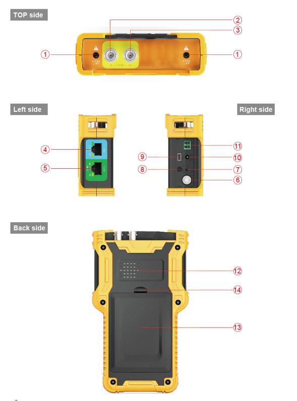
14 Top Side 1 LED Torch Light 2 Analog Video Input BNC Connector 3 Analog Video Output BNC Connector Left Side Network Port 1 (Blue) with POE Power Supply 4 POE Power Supply Indicator (Orange) Network Port 1 Link and Data Indicator (Green) Network Port 2 (Green), with POE Power Accept; Also Device 5 Charging Connector POE Power Accept Indicator (Orange) Network Port 2 Link and Data Indicator (Green) Right Side Power Switch: Press and hold for 2 seconds to turn on/off 6 the tester device. When the device is on or off, double clicking on this button will turn on/off the LED Torch Light. 7 Reset Button: Use a small tool, like a pen, to press the button inside the small hole to reboot the device when necessary. 8 Audio Input: 3.5mm audio connector 9 Mini USB Connector: Used to connect the device to a computer 10 12V/2A Output Connector: Diameter 4mm, internal pin diameter 1.65mm 11 RS485 Output: Used to control PTZ 14
15 Back Side 12 Internal Speaker 13 Battery Cover 14 Battery Cover Buckle 15
16 3. Operation Instructions 3.1 Installing Battery and Recharging The tester device uses a rechargeable lithium-ion polymer battery. To ensure safety when transporting, ensure the battery is disconnected from the tester deice. The device may leave the factory with one of the following two battery placements: 1. The battery is placed inside tester and insulated from the circuit with a thin, plastic sheet. In this case, the user should open the battery cover, take out the battery, remove the plastic sheet, then put the battery back in, and put the battery cover back on. 2. The battery is placed outside the tester. In this case, the user should open the battery cover, put in battery, and put the battery cover back on. When the battery is properly placed in the device for the first time, the tester will automatically turn on. If battery level is too low, the charge indicator will flash 3 times, and the device won t turn on. When recharging internal battery, please use the provided POE injector and RJ45 cable. Connect the POE injector data/power-out connector to network port 2 (green) using the RJ45 cable, then plug in city power. Network port 2 (orange) lights up when the internal battery is recharging. The tester uses a lithium-ion polymer battery, which does not have a memory effect. Users 16
17 can recharge the battery whenever they want. When recharging, the red battery icon ( fully charged, the light turns off. ) lights up. When the battery is The battery can also be charged using a POE switch or other POE power sources that meet the 802.3af/802.3at standard. Due to calculation deviation or other reason, the battery level can be as low as 90% when the charge light turns off. Users can ensure their battery is fully charged by extending the charge time for up to 60 minutes. Do not use a non-standard POE power supply to charge the battery. This can destroy the tester. 3.2 Lanyard Wearing Users can choose to install the lanyard. The lanyard can help handling the device, prevent dropping the device, avoid damage to the device, and prevent loss. To install lanyard, put one end of the lanyard through the hole at the head of the device, turn back and go through the tri-glide button. Tighten the lanyard and confirm that it is locked. 3.3 Basic Starting Instruction Turning the Device On and Off 17
18 To turn on the device, press and hold for more than 2 seconds. The power icon will light up green when the device is turned on. To turn off the device, press and hold more than 2 seconds. When the device is turned off, the green light will turn off after the device is fully shut down. Users can also setup the idle auto power off function Selecting Function Mode When the device is on, press the key to switch to the function select menu. Press multiple times or use the arrow keys to select a function. Wait 2 seconds or press the arrow key to enter the selected function Using the Head Side Torch Light On either on or off status, click twice quickly to turn on and off LED torch light. The LED torch light will turn off when the device is turned off. To continue to use the LED torch light when the device is off, users can simply turn it on. The LED torch will turn off every time the device turned on. This is to avoid 18

19 consuming all of the battery if LED is turned on accidentally. The head side LED is high brightness LED light. When the LED torch is on, never look straight it. Looking directly into the LED torch can cause eye burns or other accidents. 3.4 ONVIF Test The ONVIF test function is designed to act as a 3 step trouble shooting guide. It combines Ethernet tests, IP settings, camera discovery, camera authorization, video display, PTZ control, camera settings, and more. Press the mode key to enter function select and select the ONVIF TEST function. Wait 2 seconds or press the right arrow key (->). This will enter ONVIF Test Step ONVIF Test Step 1: Ethernet and IP Test A. User Interface 19
20 On this interface, blue bar is for network port 1 status information; green bar is for network port 2. The gray bar is IP test information. The bottom light blue bar is the operate tips. Within the network port status bar: 1. Link Speed of Corresponding Port When it is gray and the text reads link down, means no network connection. When this icon is white, and the text is digits and characters, 10M/100M/1000M is the link speed, FD means full duplex mode, HD means half duplex mode. The link speed can also be observed via the icon itself. 2. Ethernet Data Flow Monitor This icon shows the current Ethernet traffic flow. is the outgoing data flow in b/s, kb/s, and mb/s. is the incoming data flow in b/s, kb/s, and mb/s. 20
21 3. Packet Loss Monitor This icon is the packet transfer loss status. The displayed data shows the success rate. Normally this number is 100%. The color of this icon color differs according to the success rate, as shown in the table below: RATE No Link 100% >=99% >=95% <95% Color gray green yellow orange red 4. POE Power Supply Status This icon is for network port 1, indicating the POE power output status. The first line of text is output mode: time. 12V: The device is outputting 12V and detecting PD at the same PD. CLAS: This shows the classification of the remote POE device. PSE 48V: The remote POE device is being powered. 21
22 The second line of text shows the output power in watts. When outputting power, the actual power consumption is decided by the remote device. The tester has a max power limit. When the remote device requires more power than max power, the output will terminate automatically. 5. POE Power Accept Status This icon applies to network port 2, indicating the POE power acceptance status. The text displays the powering voltage. 6. IP Test Information (gray bar) The gray bar is the IP test information. The IP setting has 3 modes: Static IP, DHCP request, and DHCP server. B. Operation 1. Connect to network or IP cameras. Several conditions: 1 Connect to a Network Switch and 12V Power IP Cameras. Use a standard RJ45 cable to connect the switch or camera with network port 1 or 2. The network status will show on the corresponding network port bar and icons. The tester supports MDI/MDIX connection. The camera can be powered using its own 12V power adapter or using the tester s 12V/2A power output. When using the tester s 12V/2A output, please use the 12V output cable to connect the 12V output port and the camera s 12V power port. 22

23 The tester supports a maximum output of 12V/2A. When the camera consumes more than 2A, the power output will terminate. Note: If there is a POE powered device connecting to network port 1, then the 12V output is disabled. The POE power output has higher priority. 23
24 2 Connect to POE Switch and Charge the Internal Battery at the Same Time. Use a RJ45 cable to connect the POE switch and tester network port 2 (green). The orange light on network port will turn on, indicating acceptance of the POE power. If the internal battery level is below 95%, the charge light will turn on. Multiple ONVIF cameras can connect to a switch. Cameras can use their own power or POE power. 3 Connect with a POE Powered Camera. Use a RJ45 cable to connect a POE powered camera and tester to network port 1 (blue). The tester will first detect the POE device and then supply power. When powering POE device, 12V output of the tester is disabled. When a POE powered device requires more power than max power, the POE power output will terminate. The tester PSE meets the 802.3af/802.3at standard. The maximum power is 25.5W. 2. Setting IP Mode. The tester supports 3 IP modes: static IP, DHCP request, and DHCP server. These 3 modes can be switched by pressing a key: 1 DHCP Request Mode This mode is suitable when connecting to a working network. 24
25 When entering the ONVIF test, the IP mode is set to DHCP request by default. Users can switch to this mode by pressing Iris- (blue). In this mode, the tester will try to find a DHCP service in the network and get an IP. Upon success, the server assigned IP will show in the gray bar. 2 DHCP Server Mode This mode is suitable when connecting with a single IP camera that uses DHCP. Pressing the FOCUS- (yellow) key will switch to DHCP server mode. In this mode, the tester will set the local IP to static, start the DHCP server, and wait for a remote DHCP request. Be ready to assign an IP. Note: If connecting to a working network that already has a DHCP server, this will cause conflict because of multiple DHCP servers, causing some devices to get incompatible IPs and network interference. 3 Static IP Mode This mode is suitable when connecting a camera or network that uses a static IP. Press the SET key to switch to static IP mode. The IP setting screen will pop up. 25

26 Please use the flip keyboard to input the IP and use the A/S key to adjust the mask. To access internet, gateway access is also needed. When entering character d and symbol. need no switching. To select a commonly used IP, press Z (the zoom key). 26
 to go to the next step. 3.4.")
27 When done input or select, press the Iris+ key (blue) to apply. The commonly used IPs can be edited. Select an item then press the FOCUS+ key to edit. 3. Next Step When the network connect information is confirmed to be normal and the tester has acquired an IP, press the arrow key ( ) to go to the next step ONVIF Test Step 2: Discovering Cameras In this step, the tester will try to discover ONVIF cameras in the network. It will show a camera video snapshot for quick identification. Camera video information is showed as well Discovering Cameras 27

28 When entering this step, the tester software will broadcast ONVIF discover data, trying to discover ONVIF cameras. It will then add them to the list on the left. The text above the list shows the number of discovered cameras. When there are too many items on the list, then the triangle up/down prompt will show on the left. This indicates that there are more items which are not shown. Use the up/down arrow keys to select a camera in the list. The tester will automatically initialize the link with the corresponding camera, then show the camera video snapshot on the right side of screen. In this interface, pressing FOCUS- will clear the camera list and restart the discovery process. Some cameras may not respond the ONVIF discover request, or cannot reply due to different IP sub-net settings. In such a case, the user should 28
 still cannot be discovered, then users can use the manually add function. 3.4.2.2 Manually Adding a Camera Press ZOOM- key to manually add an IP camera.")
29 first return to step 1 and set the local IP to be within the same sub-net as the camera (remember your local IP cannot be in conflict with other devices on network. They should then enter step 2 to try discovering the cameras again. If the camera(s) still cannot be discovered, then users can use the manually add function Manually Adding a Camera Press ZOOM- key to manually add an IP camera. To manually add a camera, the must know the camera s exact IP and ONVIF service path. In the input bar, if finished input IP address, user can press TAB key to add default path at the end (e.g., entering and pressing the TAB key will automatically add device_service like this: After finished with input, press the Iris+ key to confirm Viewing Camera Video Snapshot and Video 29

30 Information Use the up/down arrow keys to select a camera in the left side list. After 1 to 3 seconds, a video snapshot from the corresponding camera will show on the right for quick user identification. Video information is also displayed above the snapshot, Showing resolution, frame rate, and compression method. Some cameras need ONVIF authorization. If the video information says need password, press the Iris- key to jump to the authorization screen. 30

31 Type in the user name and password then press the Iris+ ( ) key to submit Entering ONVIF Video Test Select a camera to test then press the arrow key to enter the ONVIF video test. Some cameras need RTSP authorization, and the tester will jump to the authorization screen. The RTSP authorize screen operation is same as the ONVIF authorization screen ONVIF Video Test In this step, the tester displays camera video, controls PTZ, and camera setup settings Displaying Camera Real-Time Video 31

32 When entering step 3, the tester displays camera video automatically. Video image will re-size to reserved area of the screen. To switch to full screen video display and control PTZ, press the SCR key. To setup camera settings, press the SET key ONVIF PTZ Control Pressing the SCR key will switch to full screen video display mode, and all display information will be hidden. The video image will cover most of the screen area. Due to width to high ratio differences, part of the screen could be black with nothing to display. In full screen mode, use the FOCUS+/- and arrow keys to control PTZ Camera Settings Press the SET key to enter the camera settings screen. 32

33 The left side of the display shows the settings class, and the right shows the settings details: The settings classes and details are as follows: Class Contents Camera_info Camera model, serial, brand, and other information This information cannot be altered. Network Camera network settings, like host name and DNS System Reset camera, factory default, service ports, ONVIF discover enable mainstream Camera main stream setting substream Camera sub-stream setting. If the camera has more than one sub-stream, the name of sub-stream may change. Eth0 Camera network port settings, including IP, gateway, etc. For a multi-port camera, there may be more than one port setting, and the name of port may also differ. 33
34 To select class on the left, use the ZOOM+/- keys. To select right side items, use the arrow keys. For setting of selection, use the keys to adjust. For setting of input data, use flip keyboard to input. When finished setting, press the (Iris+) key to confirm. The tester will send new settings to the camera. If the camera accepts the new settings, the setup successful prompt will show. Otherwise, failure information will show. Some cameras must be rebooted to apply new settings; this is decided by the camera ONVIF Video Digital Zoom On video display screen, pressing the 1 key will digitally zoom in, while pressing the Q key will zoom out. When the image is partly shown, a chart will be displayed on the lower right corner, showing the display ratio. 0.8X When the image is partly shown, pressing the E, S, D, and F keys will move the viewing window to inspect different portions of the image. 3.5 Analog Video Test and RS485 PTZ Control This function is used to display an analog video image, showing the video 34

35 format and signal level. It is also used to send commands though the RS485 cable to control the PTZ Connecting to Analog Camera Analog cameras are connected using the BNC connector. Use a BNC cable to connect the camera to the tester via the video input connector on the top side of the tester. The camera can be self-powered using its own power adapter or use the tester s 12V/2A power output. Note: The tester s maximum output power is 12V/2A. When the current exceeds the limit, power output will automatically stop. Be cautious when using cameras with high power IR lights. When network port 1 is connected to a POE powered device, 12V output is disabled. 35

36 3.5.2 Analog Video Test Press the MODE key to select analog video test. Wait 2 seconds, or press the arrow key to enter the analog video test. A. Video Display Area Due to varying image width to height ratios, the displayed image may not be full screen. Some parts of the screen may be black. B. Signal Information This area displays the video format, resolution, frame rate, and signal level. The signal format can be PAL/NTSC/HD-CVI * Full Screen and Portion Display of Analog Video Image After entered the analog video test function, press the SCR key to enter or 36

37 exit full screen mode. In full screen mode, the user interface is hidden. To digitally zoom, press the 1 or the Q key to zoom in or out. In digital zoom mode, a zoom chart will be displayed on the lower right corner, showing the display ratio: 2X In digital zoom mode, pressing E, S, D, and F will move the viewing window around the image to inspect different portions of the image RS485 PTZ Control On the analog video screen, pressing the SET key will bring up the RS485 PTZ setting menu: 37
38 Use the up and down arrow keys to select an item, and the left and right arrow keys to adjust it. The settings are as follows: Protocol Select RS485 PTZ protocol The tester supports many PTZ protocols. Baud Rate RS485 communication baud rate Address Address of PTZ to control. Due to different camera vendor settings, the address may be offset by +/-1. Address range is dependent on the protocol. Speed Expected PTZ speed, 1%-100% Set Preset Adjust this value, and then press the (Iris+) key to save the camera s current position to its internal storage. This function is provided by the camera. Refer to the camera manual. Go Preset Adjust this value, and then press the (Iris+) key. The camera will go to the corresponding pre-saved position at maximum speed. This function is provided by the camera, please refer to the camera manual. After setting, press the SET key to exit. Settings are applied immediately. When setting parameters, press the X (Iris-) key to restore previous values if you do not want to save the setting. Use the RS485 cable to connect the PTZ RS485 wire then use FOCUS, ZOOM, Iris and arrow keys to control the PTZ. 3.6 Analog Video Generator 38

39 Press the key to select analog video generator. Press the key or wait 2 seconds to enter the analog video generator function Analog Video Generator Screen A. Test Pattern Select: Supports pm5544 and EBU color bar B. Test Video Format: supports PAL and NTSC C. Output Video Image: The same as output video image D. Input Video Format, Resolution, and frame rate: Format supports PAL/NTSC/HD-CVI E. Input Video Level: Displayed in db. 0dB is the standard value (1vpp@75Ω) F. Input video Image: To be compared with the output image Connection of Analog Video Generator 39

40 A. Transmit generated video to remote monitor or DVR, and judge the transmission quality by inspecting the image. B. Generated video is transmitted through an optical video transmitter, received by an optical video receiver, and then returned to the tester though the video input connector. Transmission quality can be judged by comparing the image between the output pattern and video input image. 3.7 RJ45 Cable TDR Test * This function is used to test an RJ45 cable using a TDR (Time Domain Reflection) analysis method. Connection status and cable length can be measured. Connected, open, and short statuses can be detected, and cable length is displayed. The accuracy is within 1 meter. To measure a cable, only one end of the cable needs to connect to tester, and the other end should be left open Cable TDR Test Screen and Operation 40

41 Press the key to select the cable TDR test function. Press the key or wait 2 seconds to enter the TDR test function: A: Network Port 1 Icon: A tape measure icon flashes on the screen when a cable is being tested. B: Network Port 1 Test Results Display. This area displays the test results of the last measurement stands for the 4 twisted wires inside the RJ45cable. The statuses can be normal, open, or short. Normal means the other end of cable is connected with a network device, and is well terminated. The number is the cable length between tester and remote network device. Open means the other end of the cable is unconnected. The number is the cable length. Short means the other end of wire pair is a short circuit. When a cable is in poor condition or of other unknown reasons, the test may fail and Test failed will be displayed. 41
42 C: Network Port 2 Icon. Similar to A D: Network Port 2 Test Result. Similar to B When entering this function, the device will take a measurement automatically. To measure again, press ZOOM +/- to start a network port 1 or network port 2 test. To activate contiguous measurement, press the SET key. When the SET key prompt changes to Stop contiguous measure, the current status is contiguous measure. Note: Test result can be affected by temperature, moisture, cable diameter, and cable dielectric. Test results are only for reference, not for formal measurement. Contiguous measure is to help easily test multiple cables, and it will not increase test accuracy. When a cable is perfectly terminated due to really weak reflection from the cable end and there may be stronger reflection from other cable junction, then the measurement result may be shorter than actual cable length. It is recommended to disconnect the other end of the cable and measure from that end. The TDR function is only for some device models. 3.8 Network Analysis (Network Tools) Network analysis is a combination of several network tools, including 42

43 Ethernet sniff, sub-net list, and ping test. Press the key to select network analysis. Press the key or wait 2 seconds to enter network analysis. Elements on network analysis screen: A. IP Address and Mask Display: To change this setting, press the SET key, jump to the IP setting screen, and then change the setting. DHCP and static IP are supported. B.Gateway and DNS Display: To change the setting, operation is the same as the IP settings. C. Ping Destination: When the bar is yellow, use the flip keyboard to edit. IPs and domain names are both supported. D. Tool Run-Time Information display Area. E. Function Key Prompt. When prompt is highlighted, the corresponding function is available. When the prompt dims, this means another function is running, and the correspond functions is not available. 43
44 3.8.1 Ethernet Sniff Operation To use the Ethernet sniff function, network parameters or destinations don t matter. Press FOCUS+ to start. Once Ethernet sniff is started, the tester will keep listing to the network, waiting for broadcast data, detecting MAC and IP addresses. Unlisted MAC and IP addressed will be added to the list. The format of the list is XX-XX-XX-XX-XX-XX I.I.I.I; where XX is a MAC address in HEX, and I is an IP address displayed in decimal. Most network devices broadcast data packets periodically, identifying their existence. The sniff function will detected this data and discover unknown network devices. When connecting to an unknown setting and unknown IP unknown, first try using DHCP server to distribute IP to the device. If the device is not requesting an IP address, then use this sniff function to detect the device. Detecting a device using the sniff function may take 3 to 60 seconds, according to the device broadcasting frequency, and the tester will not detect a device if it remains silent. The sniff function is detecting broadcasting data packets, so devices of any sub-net and any kind could be found. Note: The sniff function does not detect uni-cast (point-to-point) packets. To exit Ethernet sniff, press the FOCUS+ key List Sub-Net Function Operation To use the list sub-net function, IP and mask should be setup, and the 44
45 subnet mask should be 24bits wide (that is the sub-net size of 256 devices). When entering the network analysis function, a section of the screen will display the current IP and mask settings. If the settings are not as wanted, press the SET key and change the settings in the IP setting screen. After the IP and mask are set, press the FOCUS- key to start the sub-net list. The sub-net list function will scan the whole sub-net. Devices being scanned must reply, so the discover rate is 100% if the device is operating normally. This sub-net list function will also measure the network latency, and display it in ms. The sub-net list display format is: XX-XX-XX-XX-XX-XX I.I.I.I N ms. Where XX is the MAC address displayed in HEX, I is the IP address displayed in decimal, and N is the network latency. Compared to the network sniff function, this function cannot detect devices with different sub-net settings, but the same sub-net detection rate is 100%. The sub-net list will take 1-10 seconds to finish. To exit the sub-net list function, press the FOCUS- key Ping Operation To use the ping function, IP address, masks and destination are needed. If the destination is a domain, then DNS and gateway are also needed. To setup IP, mask, DNS, and gateway, press the SET key, and setup on the IP setting screen. 45
46 To edit a destination, use the flip keyboard when the destination section is yellow. When you are done setting IP, mask, and destination, press the ZOOM+ key to start the ping operation. The ping test displays result in chart form as follows: Ping Average:3ms 1ms 10 7% ** 3ms % ****************** 10ms 2 1% * 30ms 0 0% 0.1s 0 0% 0.3s 0 0% 1s 0 0% 3s 0 0% Lost 0 0% The 1 st row is the latency grade; the 2 nd row is corresponding reply time; the 3 rd row is the respond time ratio; and the 4 th row is the latency chart. To exit the ping function, press the ZOOM+ key. 46
47 3.9 Record Playback The tester can take snapshots of or record input video and save them to internal storage. This function allows users to review saved snapshots and play recorded videos Device Setup This function allows users to setup some system parameters. USB storage and software upgrade functions are included in this function. Press the key to select device setup, and press the key or wait 2 seconds to enter device setup mode: Use the arrow keys to select an item to change or function to call. After settings are changed, press (Iris+) to save and apply Setting Up Automatic Power Off Time 47
48 Select the auto power off item, and adjust its settings using the keys. Automatic power off can be set between 5 minutes (minimum) and 60 minutes (maximum). When the selected time is at 5 minutes, press the key to turn off auto power off. Disabled will be displayed. Press the Iris+ (blue) key to apply the setting. When the tester is left untouched for longer than the auto power off time, the tester will automatically turn off Setting Up Key Pad Tone Select keypad tone item, and adjust the setting using the keys. The options are enable or disable. When enabled, the speaker sounds a short tone of 2-3KHZ. To apply the setting, press the Iris+ (blue) key. The keypad tone setting does not affect the audio test function Setting Screen Language The tester supports multiple languages. Select the language item then select the language desired using the keys. Press the Iris+ (blue) key to apply your selection Changing Screen Backlight Brightness 48
49 The screen backlight has 10 selectable levels. For outdoor use, a higher brightness will have better contrast, while a lower brightness will consume less battery power. Select the desired backlight brightness level using the keys. The brightness adjustment will take effect immediately Adjusting System Time and Date When system time adjustment is needed, select system time to adjust time. Use the FOCUS+/- keys to adjust the hour, the ZOOM+/- keys to adjust the minutes, and the keys to adjust seconds. To adjust system date, select the system date item. Use the FOCUS+/- keys to adjust year, the ZOOM+/- keys to adjust the month, and the keys to adjust the day. The date display format is year/month/day. After adjusting the time and date, press the Iris+ (blue) key to apply the changes System Upgrade The tester software can be upgrade online. In the device set screen, select system upgrade, the current software version will be displayed (e.g., V0027). Press the key to enter the system upgrade screen as shown below: 49


50 Connect to an internet router using the RJ45 cable, and press the SET key to setup network settings as shown below: If the network is using DHCP, the tester will automatically detect the IP settings. Otherwise, the IP settings should be entered by the user. Please consult your network manager. 50
51 After IP setup is complete, press SET key to return. The device will connect to the software upgrade server and try to find a new software version automatically. When a new version is found, the new version number and current version number will be displayed. Press the FOCUS+ key to enter the download screen. The download process is fully automatic, and an integrity check is automatically executed upon download completion. After this process, the tester will return to the upgrade screen automatically. An upgrade download may take seconds to dozens of minutes, depending on the network speed. Please use a broadband connection to upgrade. This will save you valuable time. Upon download success, a start upgrade prompt will be displayed on the screen. Press the ZOOM+ key to start the upgrade. The system will reboot automatically then enter upgrade screen. Press the SET key to start. Follow on-screen prompts to continue the process. Confirm the battery level is at least 30%. It is a good choice to connect the charger when upgrading to avoid power loss during the upgrade process. Do not open battery cover, remove the battery, or press the reset key while upgrading. This may cause system failure, and the device may not be able to boot up again USB Storage Mode Due to data sharing problems, the USB storage function is off by default. To enter USB storage mode, enter the device set screen then select the USB 51

52 Storage function. The screen will look like this: Use a USB mini-b cable to connect the tester to a computer. Further operation is the same as a common USB disk. When using USB Storage, do not press the MODE key or the power key. This will cause the USB storage device to be un-plugged from host computer, and you may lose data. To disconnect the USB connection from a computer, eject or un-mount the disk from the host system before disconnecting the cable Getting Tester Serial Number Enter the device set screen. The device serial number is shown on the last line Audio Test 52
53 The tester is equipped with an audio test function. It can be used to test microphones or other audio devices. Use 3.5MM audio cable in accessories to connect audio device. Black clamp is earth connection, red clamp is signal connection. Please connect earth first, avoid large noise during connection. If connect successful and the tester is power on, audio is play out from internal speaker Powering POE Powered Devices The tester supports POE power supply. Use a normal RJ45 cable to connect the tester network port 1 (blue) and the POE powered device. The tester will supply power to the remote device. Note: The connected POE powered device must meet 802.3af / 802.3at standards. Otherwise, the tester will not supply power. Connecting a non-poe device to network port 1 is safe. When using POE power supply, enter ONVIF test step 1 to see the POE s actual power. Maximum POE power is 25.5W. Output will terminate if power exceeds the limit. Do not connect non-standard POE power supplies to network port 1 (blue). This may damage the tester. When using POE output, the battery s operation time may be greatly reduced due to external device s power consumption. 53
54 3.13 Powering a 12V Camera The tester is equipped with 12V/2A output. The maximum output current is 2 amperes. The actual current is decided by the remote device. Use the 12V output cable to connect the 12V output port and the 12V camera. The tester will supply power to the camera. Note: If network port 1 is connecting with a standard POE powered device, the tester will supply power to the POE device because POE has a higher priority. 12V output is disabled. Note: 1. Do not connect any kind of power supply to the tester s 12V/2A output port when connected to a POE powered device. This may cause damage to the tester and/or the power supply. 2. The 12V power output maximum current is 2A. If the current exceeds the limit, 12V output is terminated. 3. When using 12V output, the battery power time will be greatly reduced due to remote power consumption. 54
55 4. Specifications Model Physical Port Network Port Function Port IPC Test Protocol Ethernet Test IP Configuration IPC Test HDCVI & Analog Test SD signal Format HD video signal Resolution Signal Level Camera Test HDCVI OSD PTZ Control Protocol Smart Tester 2*10/100/1000M RJ45 port, support switch mode 2*BNC port (Video IN and Video OUT), 1*RS485, 1*Audio In, 1*USB, 1*Reset ONVIF 2.4.1, RTSP, RTP 10/100/1000M Ethernet link test, loop detect, Ethernet traffic flow monitor, link quality test static IP/ DHCP client/ DHCP server Discover camera, real time video, camera configuration, PTZ control, audio test, full screen preview and 8x digital zoom, snapshot, record video(recording original data stream) NTSC, PAL HDCVI D1, 720P, 1080P 1Vpp Real time video, PTZ control, audio test, full screen preview and 8x digital zoom, snapshot, record video(h.264) Camera configuration More than 30 protocols including Dahua, Pelco-D/P, Samsung, Panasonic, Lilin, Yaan
56 etc. Baud Rate Detection TDR detection POE test Network Analyze Analog Video Generator Record Playback System Specification Screen Operation Method Auto Power Off Keyboard Tone Upgrade Power Power Input POE Injector Battery Power Output 150, 300, 600, 1200, 2400, 4800, 9600, 19200bps 0~150m net cable detection, resolution 1m PD test PSE test Sniff, list subnet, ping Generate PAL/ NTSC video signal of various test pattern Support local playback 4.0 inch TFT 800*RGB*480(WVGA) resolution, 16.7M color, backlight brightness adjustable Power key, 12 control keys, QWERTY flip keyboard with 45 keys Disable/ 5~60 minutes Enable/ Disable Support online upgrade POE source or POE injector Input AC100~230V 50~60Hz, output 48V/15w Dedicate battery, user replaceable, 7.4V lithium-ion polymer battery, capacity 22.2Wh POE (802.3af, 802.3at) DC12V 2A 56
57 Charging time 3~4 hours, working time 10 Time hours Other Internal Storage 8GB flash LED Light 2*35lm LED light Working Temperature -10 ~+55 Working Humidity 30%~90% Dimensions 190x113x37mm Weight 1.6kg 5. Post-Sale Service If the product encounters any problems, please contact the product manufacture or resale agent. 57
HD COMBINE TESTER User Manual
 HD COMBINE TESTER User Manual HD Combine Tester Thank you for purchasing the HD Combine Tester. Please read this manual before using the HD Combine tester, and use it properly. Before using the HD Combine
DS-7200HVI/HFI-SH Series DVR Quick Operation Guide
 DS-7200HVI/HFI-SH Series DVR Quick Operation Guide UD.6L0202B0019A01 Thank you for purchasing our product. If there is any question or request, please do not hesitate to contact dealer. This manual is
How-to Note: Quickstart: ITM9000 [This note applies to ITM9000 (handheld tester)] Contents. Overview. Materials Included
![How-to Note: Quickstart: ITM9000 [This note applies to ITM9000 (handheld tester)] Contents. Overview. Materials Included](/thumbs/93/112907906.jpg "How-to Note: Quickstart: ITM9000 [This note applies to ITM9000 (handheld tester)] Contents. Overview. Materials Included") How-to Note: Quickstart: ITM9000 [This note applies to ITM9000 (handheld tester)] Contents Overview... 1 Materials Included... 1 Getting Started... 2 Main Operations... 4 Reference / Additional Notes...
How-to Note: Quickstart: ITM9000 [This note applies to ITM9000 (handheld tester)] Contents Overview... 1 Materials Included... 1 Getting Started... 2 Main Operations... 4 Reference / Additional Notes...
-TECH DIGITAL. Explore The High DefinitionWorld. Website: Hot Line: [US] USER MANUAL
![-TECH DIGITAL. Explore The High DefinitionWorld. Website: Hot Line: [US] USER MANUAL](/thumbs/80/80689593.jpg "-TECH DIGITAL. Explore The High DefinitionWorld. Website: Hot Line: [US] USER MANUAL") -TECH DIGITAL Explore The High DefinitionWorld Website: www.jtechdigital.com Hot Line: 1-888-610-2818[US] USER MANUAL J-Tech Digital ProAV H.264 Encoder/Decoder Many to Many HDMI Extender RoHS 1 Operating
-TECH DIGITAL Explore The High DefinitionWorld Website: www.jtechdigital.com Hot Line: 1-888-610-2818[US] USER MANUAL J-Tech Digital ProAV H.264 Encoder/Decoder Many to Many HDMI Extender RoHS 1 Operating
Digital Video Recorder
 Digital Video Recorder Quick Operation Guide UD.6L0202B0067A02 Thank you for purchasing our product. If there is any question or request, please do not hesitate to contact dealer. This manual is applicable
DINOX&Digital&Video&Recorder&
 DINOX&Digital&Video&Recorder& & & & & & & & & & &&&Quick&Operation&Guide& UD.7L0X02B1228B01& Thank you for purchasing our product. If there is any question or request, please do not hesitate to contact
Quick Operation Guide of LTN7700/7600 Series NVR
 Quick Operation Guide of LTN7700/7600 Series NVR UD.6L0202B0042A02 Thank you for purchasing our product. If there is any question or request, please do not hesitate to contact dealer. This manual is applicable
OPERATING INSTRUCTIONS TOM-0431IP
 OPERATING INSTRUCTIONS TOM-0431IP Table of Contents FCC Information -------------------------------------------------------------------- 2 Safety and Environmental Precautions ------------------------------------------------
Tenma Multifunction IP Testers
 Resolution 1280*800 1280*800 1920*1200 Retina Display 960*540 Screen Size 7.0 inch 7.0 inch 7.0 inch 4.3 inch Price USD226.40 USD249.70 USD305.60 USD228.80 MOQ 50 pcs 50 pcs 50 pcs 50 pcs Battery capacity
Model#: IN-MDRI3MF. Hardware User Manual. 3MP Indoor Mini Dome with Basic WDR, Fixed lens. (PoE) Ver. 2013/02/04
 Ver. 2013/02/04") Model#: IN-MDRI3MF 3MP Indoor Mini Dome with Basic WDR, Fixed lens Hardware User Manual (PoE) Ver. 2013/02/04 Table of Contents 0. Precautions 3 1. Introduction 4 Package Contents... 4 Features and Benefits...
Model#: IN-MDRI3MF 3MP Indoor Mini Dome with Basic WDR, Fixed lens Hardware User Manual (PoE) Ver. 2013/02/04 Table of Contents 0. Precautions 3 1. Introduction 4 Package Contents... 4 Features and Benefits...
B. The specified product shall be manufactured by a firm whose quality system is in compliance with the I.S./ISO 9001/EN 29001, QUALITY SYSTEM.
 VideoJet 8000 8-Channel, MPEG-2 Encoder ARCHITECTURAL AND ENGINEERING SPECIFICATION Section 282313 Closed Circuit Video Surveillance Systems PART 2 PRODUCTS 2.01 MANUFACTURER A. Bosch Security Systems
H.264 HDMI Extender over IP Extender With LED, Remote, POE, RS232 Operating Instruction
 H.264 HDMI Extender over IP Extender With LED, Remote, POE, RS232 Operating Instruction 1 Introduction This HDMI over IP Extender use the advanced H.264 as the compression type, which makes it occupy lower
CI-218 / CI-303 / CI430
 CI-218 / CI-303 / CI430 Network Camera User Manual English AREC Inc. All Rights Reserved 2017. l www.arec.com All information contained in this document is Proprietary Table of Contents 1. Overview 1.1
EVE ONE. One-channel IP video encoder
 SIQURA EVE ONE One-channel IP video encoder DESCRIPTION The Siqura EVE ONE is a compact, easy-to-use video encoder that encodes analogue video to an H.264 IP stream. It makes the migration to IP affordable
CCE900-IP-TR. User s Guide
 CCE900-IP-TR CCE900-IP-T & CCE900-IP-R User s Guide i-tech Company LLC TOLL FREE: (888) 483-2418 EMAIL: info@itechlcd.com WEB: www.itechlcd.com 1. Introduction The CCE900-IP-T & CCE900-IP-R is a solution
INFORMATION TO USER CAUTION RISK OF ELECTRIC SHOCK, DO NOT OPEN
 INFORMATION TO USER CAUTION RISK OF ELECTRIC SHOCK, DO NOT OPEN! CAUTION: TO REDUCE THE RISK OF ELECTRIC SHOCK, DO NOT REMOVE COVER (OR BACK). NO USER SERVICEABLE PARTS INSIDE. REFER SERVICING TO QUALIFIED
Multi Tester. Multi Tester. Rapport III / Rapport III-PRO. Rapport -10HD/PRO. Rapport Mini Professional CCTV Tester Rapport. Image.
 Multi Tester Multi Tester Image Model# Features Rapport Mini Professional CCTV Tester Rapport Rapport -10HD/PRO Multi-Format Input Monitor Rapport III / Rapport III-PRO Multi Functional CCTV Tester MAX
EVD-L04/100A1-960, EVD-L08/200A1-960 and. EVD-L16/400A1-960 DVRs. Quick Operation Guide
 EVD-L04/100A1-960, EVD-L08/200A1-960 and EVD-L16/400A1-960 DVRs Quick Operation Guide Thank you for purchasing our product. If there is any question or request, please do not hesitate to contact dealer.
H.264 HDMI Extender over IP Extender With LED, Remote, POE, RS232 WolfPack Operating Instruction
 H.264 HDMI Extender over IP Extender With LED, Remote, POE, RS232 WolfPack Operating Instruction 1 Introduction This WolfPack HDMI over IP Extender use the advanced H.264 as the compression type, which
Model#: IN-DI2MIRF 2MP Indoor Dome with True Day/Night, IR, Basic WDR, Fixed lens
 Model#: IN-DI2MIRF 2MP Indoor Dome with True Day/Night, IR, Basic WDR, Fixed lens Hardware User Manual (PoE) Ver.2013/01/17 Table of Contents 0. Precautions 3 1. Introduction 4 Package Contents...4 Features
H.264 HDMI Extender over IP Extender With LED, Remote, RS232. Operating Instruction
 SC08.6010 H.264 HDMI Extender over IP Extender With LED, Remote, RS232 Operating Instruction 1 Introduction The SC08.6010 transmitters and receivers can be used as point to point extenders up to 120m or
Video Server SED-2100R/S. Quick Installation Guide
 Video Server SED-2100R/S Quick Installation Guide Feb.10,2006 1 1 Getting Started 1.1 PACKAGE CONTENTS SED-2100 Warranty Card Software CD Hook up & Screws Terminal Blocks for Power & DI/O Power Adaptor
BRIGHTLINK HDMI EXTENDER OVER ETHERNET - H METER MODEL: BL-EXT-IP-264
 BRIGHTLINK HDMI EXTENDER OVER ETHERNET - H.264-120 METER MODEL: BL-EXT-IP-264 Operating Instructions BRIGHTLINKAV.COM 1 Introduction This HDMI over IP Extender use the advanced H.264 as the compression
Dell Wyse 5030 PCoIP Zero Client
 Dell Wyse 5030 PCoIP Zero Client User Guide Regulatory Model: PxN Regulatory Type: PxN001 Notes, cautions, and warnings NOTE: A NOTE indicates important information that helps you make better use of your
Part 1 Basic Operation
 This product is a designed for video surveillance video encode and record, it include H.264 video Compression, large HDD storage, network, embedded Linux operate system and other advanced electronic technology,
VITEK VTM-TLM191 VTM-TLM240
 VTM-TLM191 VTM-TLM240 19 & 24 Professional LED Monitors with HDMI, VGA, and Looping BNC VITEK FEATURES 19 & 24 Wide Screen LED Display Panel HDMI, VGA, and Looping BNC Composite Video Inputs & Stereo Audio
BY-HPE11KTA. Operating Instructions. Coaxial - LAN Converter with PoE function. Indoor Use Only. Model No. Attached Installation Guide
 Operating Instructions Coaxial - LAN Converter with PoE function Model No. Indoor Use Only BY-HPE11KTA Attached Installation Guide Before attempting to connect or operate this product, please read these
Package Contents. LED Protocols Supported. Safety Information. Physical Dimensions
 Pixel Triton Table of Contents Package Contents... 1 Safety Information... 1 LED Protocols Supported... 1 Physical Dimensions... 1 Software Features... 2 LED Status... 2 Power... 2 Activity LED... 2 Link
THD601DC Set-top box
 THD601DC Set-top box Contents 1. Safety... 1 2. Appearance... 2 3. Rear Panel Connection... 3 4. Remote... 4 5 First Time Set-Up... 7 6. Network Settings... 8 6.1 Available Networks and Checking Current
SCode V3.5.1 (SP-501 and MP-9200) Digital Video Network Surveillance System
 Digital Video Network Surveillance System") V3.5.1 (SP-501 and MP-9200) Digital Video Network Surveillance System Core Technologies Image Compression MPEG4. It supports high compression rate with good image quality and reduces the requirement of
V3.5.1 (SP-501 and MP-9200) Digital Video Network Surveillance System Core Technologies Image Compression MPEG4. It supports high compression rate with good image quality and reduces the requirement of
SCode V3.5.1 (SP-601 and MP-6010) Digital Video Network Surveillance System
 Digital Video Network Surveillance System") V3.5.1 (SP-601 and MP-6010) Digital Video Network Surveillance System Core Technologies Image Compression MPEG4. It supports high compression rate with good image quality and reduces the requirement of
V3.5.1 (SP-601 and MP-6010) Digital Video Network Surveillance System Core Technologies Image Compression MPEG4. It supports high compression rate with good image quality and reduces the requirement of
Instructions for Use: Video Inspection Scope with Display
 Instructions for Use: Video Inspection Scope with Display Brand Name of Product Video Inspection Scope Generic Name of Product Video Inspection Scope Product Code Number(s) FIS-004 Intended Use For visually
PLEASE READ THIS PRODUCT MANUAL CAREFULLY BEFORE USING THIS PRODUCT.
 Features The AVG-HD400 is an HDBT 2.0 transceiver set which contains a transmitter and a receiver. Compliant with HDMI 1.4 & HDCP 2.2, it is able to transmit high-definition signals up to 4Kx2K@60Hz. The
Video Extender DS128 DSRXL. Instruction Manual. 8-Port Cat5 VGA Digital Signage Broadcaster with RS232 and Audio
 DS128 DSRXL Instruction Manual Video Extender 8-Port Cat5 VGA Digital Signage Broadcaster with RS232 and Audio Cat5 VGA Digital Signage Receiver with RS232 and Audio FCC Compliance Statement This equipment
SECTION 686 VIDEO DECODER DESCRIPTION
 686 SECTION 686 VIDEO DECODER DESCRIPTION 686.01.01 GENERAL A. This specification describes the functional, performance, environmental, submittal, documentation, and warranty requirements, as well as the
Mobile IP Camera C6010E
 Mobile IP Camera C6010E Streamax Technology Co., Ltd. Thanks for Using Streamax Mobile IP Camera This manual aims at providing reference for Mobile IP Camera installation and use. Here you can find all
HDCVI Camera User s Manual
 HDCVI Camera User s Manual Version 1.0.3 Table of Contents 1 General Introduction... 1 1.1 Overview... 1 1.2 Features... 1 2 Device Framework... 2 3 Installation... 5 Model A... 5 Model B1 and B2... 6
OWNER S MANUAL MOTORIZED 7 WIDE TFT LCD COLOR MONITOR CNT-701
 OWNER S MANUAL PW MOTORIZED 7 WIDE TFT LCD COLOR MONITOR CNT-701 ANY CHANGES OR MODIFICATIONS IN CONSTRUCTION OF THIS UNIT DEVICE WHICH IS NOT APPROVED BY THE PARTY RESPONSIBLE FOR COMPLIACE COULD VOID
1CHDVRD1 USER MANUAL. These instructions apply to unit model 1CHDVRD1 only. Please read carefully before use.
 These instructions apply to unit model 1CHDVRD1 only. Please read carefully before use. 1CHDVRD1 USER MANUAL Description Description... 03 Features... 03 Notes... 03 Packing List... 04 Technical Specifications...
DS-7204/7208/7216HVI-ST Series DVR Technical Manual
 DS-7204/7208/7216HVI-ST Series DVR Technical Manual Notices The information in this documentation is subject to change without notice and does not represent any commitment on behalf of HIKVISION. HIKVISION
Preset 10 Ethernet Interface Configuration & Owner s Manual
 Preset 10 Ethernet Interface Configuration & Owner s Manual model: PRE10E-A Doug Fleenor Design, Inc. 396 Corbett Canyon Road Arroyo Grande, CA 93420 (805) 481-9599 Voice and FAX Manual Revision 0 September
DS-7200HFI-SL Series DVR. Technical Specification
 DS-7200HFI-SL Series DVR Technical Specification Notices The information in this documentation is subject to change without notice and does not represent any commitment on behalf of HIKVISION. HIKVISION
AVE HOME FAGOR CVBS TO DVB-T ENCODER MODULATOR. Fagor Electr6nica
 AVE HOME CVBS TO DVB-T ENCODER MODULATOR FAGOR Fagor Electr6nica TABLE OF CONTENTS 1. SPECIFICATIONS... 12 1.1 Product Overview... 12 1.2 Appearance and Description... 12 1.3 Diagram... 13 1.4 Characteristics...
Kramer Electronics, Ltd. USER MANUAL. Model: VS x 1 Sequential Video Audio Switcher
 Kramer Electronics, Ltd. USER MANUAL Model: VS-120 20 x 1 Sequential Video Audio Switcher Contents Contents 1 Introduction 1 2 Getting Started 1 2.1 Quick Start 2 3 Overview 3 4 Installing the VS-120 in
NX-series User Manual
 NX-series User Manual http://www.iviewtech.com 1 CONTENT INDEX 1 NX-SERIES OVERVIEW... 4 1.1. NX-Series Features 4 1.2. NVR CONTROL PANEL 5 1.3. NVR BACK PANEL 5 2 GETTING STARTED... 8 3 LIVE VIEW... 10
Model: S-4904T/R. Wireless HD Transmission System. User Manual. Please read this User Manual throughout before using.
 Model: S-4904T/R Wireless HD Transmission System User Manual Please read this User Manual throughout before using. Preface Congratulations on your purchase of this product. Please read this user manual
M-CT6 Camera-Top Monitor
 M-CT6 Camera-Top Monitor Owner s Manual 1 Thank you for purchasing a Marshall M-CT6 camera-top monitor. The M-CT6 is a great tool for focusing, composing, and viewing images/video clips directly from your
Product Operation Manual
 Product Operation Manual MSHRC080W Network IP Camera Microseven Systems, Inc. Walnut, California 91789, USA - 2 - First Edition (April 2008) Copyright Notice Copyright 2002-2008 Microseven Systems, Inc.
Hardware User s Manual
 Hardware User s Manual Megapixel Day & Night Economy Bullet Network Camera English 1 Table of Contents Before You Use This Product... 2 Regulatory Information... 3 Chapter 1 - Package Contents... 4 Chapter
VIDEO ALARM VERIFICATION UNIT VIVER
 VIDEO ALARM VERIFICATION UNIT VIVER viver_en 09/08 The VIVER module provides remote video alarm verification, based on image sequences transmitted from cameras installed in the protected facility. The
16-CH Color Full Duplex Multiplexer Instruction Manual
 16-CH Color Full Duplex Multiplexer Instruction Manual 707-V1.5(S) Index: 1. Safety Warning 3 2. Introduction 3 3. Features 4 4. Specification 5 5. Front Panel Keypad 6 6. Back Panel Connection 10 7. Menu
Model: S-1071H 7" Broadcast On-camera 3GSDI&HDMI LCD Monitor. User Manual. Please read this User Manual throughout before using.
 Model: S-1071H 7" Broadcast On-camera 3GSDI&HDMI LCD Monitor User Manual Please read this User Manual throughout before using. Preface Congratulations on your purchase of this product. Please read this
ACM-1431 Series. IP IR D/N CCD Outdoor PoE Bullet Camera. (DC 12V / PoE) Ver. 2012/3/12
 Ver. 2012/3/12") ACM-1431 Series IP IR D/N CCD Outdoor PoE Bullet Camera (DC 12V / PoE) Ver. 2012/3/12 Table of Contents 0. Precautions 3 1. Introduction 4 Package Contents... 4 Features and Benefits... 5 Safety Instructions...
ACM-1431 Series IP IR D/N CCD Outdoor PoE Bullet Camera (DC 12V / PoE) Ver. 2012/3/12 Table of Contents 0. Precautions 3 1. Introduction 4 Package Contents... 4 Features and Benefits... 5 Safety Instructions...
A. All equipment and materials used shall be standard components that are regularly manufactured and used in the manufacturer s system.
 SPECTRA MINI SERIES DOME SYSTEM, NTSC/PAL TECHNICAL SPECIFICATIONS SECURITY SYSTEM DIVISION -- 28 ELECTRONIC SAFETY AND SECURITY LEVEL 1 28 20 00 ELECTRONIC SURVEILLANCE LEVEL 2 28 23 00 VIDEO SURVEILLANCE
WJ-GXE500 (NTSC) WJ-GXE500E (PAL)
 WJ-GXE500E (PAL)") Network video encoder WJ-GXE500 (NTSC) WJ-GXE500E (PAL) Security & AV Systems Business Unit Panasonic System Networks Company Key Features Same Uniphier-DSP as WV-NP502 Full frame rate video for all four
Network video encoder WJ-GXE500 (NTSC) WJ-GXE500E (PAL) Security & AV Systems Business Unit Panasonic System Networks Company Key Features Same Uniphier-DSP as WV-NP502 Full frame rate video for all four
Marshall. M-CT5 Camera-Top Monitor Owner s Manual M-CT5. Camera-Top Monitor. Owner s Manual
 M-CT5 Camera-Top Monitor Owner s Manual Dear users: Thank you for purchasing Marshall s M-CT5-CE6 HD DSLR LCD Monitor. This 5 Pro HD LCD Monitor is designed to be used as an external video display, allowing
Multi-function Portable. HD LCD Monitor. User Manual
 Multi-function Portable HD LCD Monitor User Manual Product description: Thank you for purchasing our photography, broadcast color LCD Monitor kit. This product adopts proprietary digital signal processing
Broadcast A/V Division M-LYNX-702 V.3. Dual 7 LCD Display. User Manual
 Broadcast A/V Division M-LYNX-702 V.3 Dual 7 LCD Display User Manual 1. Package Includes Table of Contents 1. Package Includes Table of Contents 01 02 One M-LYNX-702 Monitor One universal AC power adapter
Broadcast A / V Division M-LYNX-702 V.3. Dual 7 LCD Display. User Manual
 Broadcast A / V Division M-LYNX-702 V.3 Dual 7 LCD Display User Manual Table of Contents Table of Contents 1. Package Includes 2. Product Description 2.1 Front Panel 2.2 Rear Panel Connections 3. On-Screen
Usermanual. P2K-HL3E1 1080p HDMI Extender over IP P2K-HL3E1-P 1080p HDMI Extender over IP with PoE P2K-HRSL3E1 / P2K-LHRS1E3
 Usermanual P2K-HL3E1 1080p HDMI Extender over IP P2K-HL3E1-P 1080p HDMI Extender over IP with PoE P2K-HRSL3E1/ P2K-LHRS1E3 P2K-HRSL3E1 / P2K-LHRS1E3 P2K-HRSL3E1-P / P2K-LHRS1E3-P Partilink Technology Co.,
Installation & Operational Manual
 Radiant Communications Corporation 5001 Hadley Road South Plainfield NJ 07080 Tel (908) 757-7444 Fax (908) 757-8666 WWW.RCCFIBER.COM QRF5000M MDU ENCODER Installation & Operational Manual Rev.A2 1. Introduction
Single cable multiswich programmer PC102W
 Single cable multiswich programmer PC102W 1. Product description The PC102W - single cable multiswich programmer (in the text - programmer) is useful instrument while configuring and troubleshooting SAT
F M2SDI 2 Ch Tx & Rx. HD SDI Fiber Optic Link with RS 485 & Aux. User Manual
 User Manual F M2SDI 2 Ch Tx & Rx HD SDI Fiber Optic Link with RS 485 & Aux User Manual CHAPTER 1. SYSTEM INTRODUCTION 1.1 OVERVIEW 1.2 FEATURE 1.3 APPLICATION CHAPTER 2. F M2SDI ENCLOSURES 2.1 FRONT PANEL
AN2 Series. 900tvl. CMOS Technology High Resolution Sensor. elinetechnology.com P/N 01.BSM V1.0
 AN2 Series 900tvl CMOS Technology High Resolution Sensor P/N 01.BSM.16.2000030 V1.0 Product Made in China under ISO9001 & ISO1400 standards Manual Printed in China v1.0 elinetechnology.com CAUTION RISK
Displays Open Frame Monitor Model Number: AND-TFT-150Bxx
 Displays 15.0 Open Frame Monitor Model Number: AND-TFT-150Bxx The AND-TFT-150Bxx 15.0 Open Frame Monitor series are rugged, high performance Industrial LCD Monitors, designed for commercial and industrial
Start Up or Shut Down Hunting Function. Using the Receiver. If there is a short circuit in the cable, it will display as follows:
 If there is a short circuit in the cable, it will display as follows: Push key (No) to exit calibration function. Push key (Yes) to repeat measurement process. 11 Note: The calibration will recover the
EVD-L04/100A1-960 EVD-L08/200A1-960 EVD-L16/400A1-960
 EVD-L04/100A1-960 EVD-L08/200A1-960 EVD-L16/400A1-960 www.eurovideo-cctv.com Main Features Main stream supports encoding at up to WD1 resolution in real time and sub stream at CIF/QCIF resolution. Simultaneous
STUDIOVISION SRM-7X2-LT INPUT INPUT MENU. Dual 7 Rack Mount Monitors STUDIOVISION SRM-7X2-LT ENTER ENTER MENU. user MANUAL
 MENU STUDIOVISION SRM-7X2-LT Dual 7 Rack Mount Monitors STUDIOVISION SRM-7X2-LT PUT PUT MENU ENTER ENTER FN FN 1 2 user MANUAL TRODUCTION Thank you for choosing Elvid. The Elvid SRM-7X2-LT StudioVision
DTL-4800P. Digital Real Time Recording VCR
 Digital Real Time Recording VCR Digitally encoded picture of more than 520 TV line horizontal resolution Frame recording and frame playback capability Digital recording on S-VHS tapes Packet recording
Ultra-ViewRF 8HD Director Monitor. User Operation Manual
 Ultra-ViewRF 8HD 5.8GHz Wireless Director Monitor User Operation Manual 17.1.2013 v2_7 Video Equipment Rentals - VER 912 Ruberta Avenue Glendale, CA 91201 - U.S.A. Office 818-956-1444 Table of Contents
HDMI 2.0 Multiview Video Processor
 Product Data HDMI 2.0 Multiview Video Processor VP-QV41 Introduction The Partilink VP-QV41 Multiview Video Processor is a simple, cost-effective video scaler designed to enable a 4K@60Hz, HD, SD computer
PROFESSIONAL GRADE TOOLS THAT ARE EASY TO USE REVOLUTIONARY TECHNOLOGY (YOU CAN AFFORD) BYTE BROTHERS 2010 PRODUCT CATALOG
 BYTE BROTHERS 2010 PRODUCT CATALOG") Network Test and Certification PROFESSIONAL GRADE TOOLS THAT ARE EASY TO USE REVOLUTIONARY TECHNOLOGY (YOU CAN AFFORD) BYTE BROTHERS 2010 PRODUCT CATALOG QUESTION: HOW DO TOOLS GROW YOUR LOW VOLTAGE BUSINESS?
Network Test and Certification PROFESSIONAL GRADE TOOLS THAT ARE EASY TO USE REVOLUTIONARY TECHNOLOGY (YOU CAN AFFORD) BYTE BROTHERS 2010 PRODUCT CATALOG QUESTION: HOW DO TOOLS GROW YOUR LOW VOLTAGE BUSINESS?
Kramer Electronics, Ltd. USER MANUAL. Model: 900xl. Power Amplifier
 Kramer Electronics, Ltd. USER MANUAL Model: 900xl Power Amplifier Introduction Contents 1 Introduction 1 2 Getting Started 1 2.1 Recycling Kramer Products 1 3 Overview 2 4 Your 900xl Power Amplifier 3
Intelligent Security and Fire Ltd
 User Manual Product ranges covered by this manual Vi-P14 Vi-P14A Document Reference Date Firmware Vi-Q4C1 Viq601a.doc 26/11/2009 From Viq001a21 Videoswitch Telephone 01252-851510 Ocean House, Redfields
HDCVI Camera User s Manual
 HDCVI Camera User s Manual Version 1.0.0 Table of Contents 1 General Introduction... 1 1.1 Overview... 1 1.2 Features... 1 2 Device Framework... 2 3 Device Cable Structure... 4 4 Device Installation...
Analog HD video over fiber converters for smart HD CCTV
 Our AHD Video over Fiber Converters can simultaneously transmit 1-16 channels AHD over one multimode or single-mode optical fiber. Electronic and optical adjustments are never required. LED indicators
LOCAL MONITORING RECORDING HARDDISK MANAGEMENT ALARM & EXCEPTION BACKUP
 FEATURES User-friendly GUI for easy operation Up to 1024 768 resolution Simultaneous VGA and 4CIF/2CIF/CIF resolution Normal and event recording parameters configurable per individual camera Partial digital
DS-2CE56D0T-IRF HD1080p IR Turret Camera
 DS-2CE56D0T-IRF HD1080p IR Turret Camera Key Features 2 megapixel high performance CMOS Analog HD output, up to 1080p resolution Day/Night switch Smart IR Up to 20 m IR distance Switchable TVI/AHD/CVI/CVBS
FOTS100 User Manual. BIOPAC Systems, Inc. Opsens Inc. 42 Aero Camino, Goleta, CA Tel (805) , Fax (805)
 , Fax (805)") FOTS100 User Manual BIOPAC Systems, Inc. 42 Aero Camino, Goleta, CA 93117 Tel (805) 685-0066, Fax (805) 685-0067 WWW.BIOPAC.COM 1 WARRANTY All products manufactured by Opsens inc. are warranted to be free
FOTS100 User Manual BIOPAC Systems, Inc. 42 Aero Camino, Goleta, CA 93117 Tel (805) 685-0066, Fax (805) 685-0067 WWW.BIOPAC.COM 1 WARRANTY All products manufactured by Opsens inc. are warranted to be free
SX7. Saga 7" Super Bright HDMI/3G-SDI Field Monitor with 3D-LUTs. Quick Start Guide. What s Included CHECKED BY
 SX7 Quick Start Guide Saga 7" Super Bright HDMI/3G-SDI Field Monitor with 3D-LUTs What s Included 1 x Saga X7 Monitor 1 x V-Mount Plate (Attached) 1 x Mini-XLR to P-TAP Cable 1 x Dual Sony L Battery Adapter
Digital Real Time Recording VCR
 Digital Real Time Recording VCR Digitally encoded picture of more than 520 TV line horizontal resolution Frame recording and frame playback capability Digital recording on S-VHS tapes Packet recording
User Manual PS-684. HDBaseT Extender Kit 70m. All Rights Reserved. Version: UHBT70P_2016V1.2
 User Manual PS-684 All Rights Reserved Version: UHBT70P_2016V1.2 Preface Read this user manual carefully before using this product. Pictures shown in this manual is for reference only, different model
Delvcam DELV-HD7-4K User Guide
 Delvcam DELV-HD7-4K User Guide 7" 4K Compatible 1080P Camera Top Monitor with Audio Meter IMPORTANT SAFETY INSTRUCTIONS Read manual before using this product. Keep manual for future reference. Do not place
FS3. Quick Start Guide. Overview. FS3 Control
 FS3 Quick Start Guide Overview The new FS3 combines AJA's industry-proven frame synchronization with high-quality 4K up-conversion technology to seamlessly integrate SD and HD signals into 4K workflows.
Platinum Tools Inc. All rights reserved. 5/12 Voice, Data, Video + Length GENERAL SPECIFICATIONS WARNINGS
 Voice, Data, Video + Length Instruction Sheet: P/N T9 GENERAL SPECIFICATIONS The Platinum Tools, VDV MapMaster.0 is a portable voice-data-video cable tester with length measurement. It tests and troubleshoots
HDCVI Camera User s Manual
 HDCVI Camera User s Manual Version 1.0.2 Table of Contents 1 General Introduction... 1 1.1 Overview... 1 1.2 Features... 1 2 Device Framework... 2 3 Installation... 5 3.1 Installation for Model A... 5
J6 User Manual. User Manual. Multi-Screen Splicing Processor J6. Xi an NovaStar Tech Co., Ltd. Rev1.0.1 NS
 J6 User Manual User Manual Multi-Screen Splicing Processor J6 Rev1.0.1 NS160110162 Statement Dear users, You are welcome to use the J6, a multi-screen splicing processor of Xi'an NovaStar Tech Co., Ltd.
AD2612 DVB TS SCRAMBLER USER S MANUAL
 AD2612 DVB TS SCRAMBLER USER S MANUAL CONTENTS 1 SAFETY INSTRUCTIONS ------------------------------------------------------------ 1-1 2 COMPOSITIONS OF SYSTEM AND OPERATING PRINCIPLE----------- 2-1 2.1
MODE MENU /F1 /F2 F3 F4 PLCMHD80
 MODE MENU /F1 /F2 F3 F4 PLCMHD80 ! To insure best use of the unit, please read the user s manual carefully CAUTION 1. Do not use any damaged or leaking battery, if using a battery to power. 2. Do not expose
DS-7200HVI-ST/RW Series DVR. Technical Manual
 DS-7200HVI-ST/RW Series DVR Technical Manual Notices The information in this documentation is subject to change without notice and does not represent any commitment on behalf of HIKVISION. HIKVISION disclaims
Video Series. HCS-4311M Professional Mixed Matrix for Conference 8.2. HCS-3313C High Quality Speed Dome Camera (ceiling) 8.5
 8.5") Video Video Series Series Video Tracking System 8.2 HCS-4311M Professional Mixed Matrix for Conference 8.2 HCS-3313C High Quality Speed Dome Camera (ceiling) 8.5 HCS-3313D High Quality Speed Dome Camera
Video Video Series Series Video Tracking System 8.2 HCS-4311M Professional Mixed Matrix for Conference 8.2 HCS-3313C High Quality Speed Dome Camera (ceiling) 8.5 HCS-3313D High Quality Speed Dome Camera
Model: DT-X92H 2. 9 Rack Mount Broadcast 3GSDI LCD Monitor. User Manual. Ver:V1.0.0V01. Please read this User Manual throughout before using.
 Model: DT-X92H 2 9 Rack Mount Broadcast 3GSDI LCD Monitor User Manual Ver:V1.0.0V01 Please read this User Manual throughout before using. Preface Congratulations on your purchase of this product. Please
User s Manual. Digital Switch Part #: DL-HDS21 Part #: DL-HDS41
 User s Manual Digital Switch Part #: DL-HDS21 Part #: DL-HDS41 TABLE OF CONTENTS 1-1 Table of Contents 1-2 Welcome and Safety Notes 1-3 Product Description and General Specifications 1-4 Environmental
VIDEO GRABBER. DisplayPort. User Manual
 VIDEO GRABBER DisplayPort User Manual Version Date Description Author 1.0 2016.03.02 New document MM 1.1 2016.11.02 Revised to match 1.5 device firmware version MM 1.2 2019.11.28 Drawings changes MM 2
Transmitter Interface Program
 Transmitter Interface Program Operational Manual Version 3.0.4 1 Overview The transmitter interface software allows you to adjust configuration settings of your Max solid state transmitters. The following
DS-9600NI-XT NVR Series
 DS-9600NI-XT NVR Series Introduction: DS-9600NI-XT series NVR (Network Video Recorder) is a new generation recorder developed by Hikvision independently. Combined with multiple advanced technologies, such
HD-1603 Single Input MPEG-4 DVB-T HD Encoder/Modulator User Guide and Install Manual
 ZyCastR digi-mod HD Range digi-mod HD-1603 www.digi-modbyzycast.com HD-1603 Single Input MPEG-4 DVB-T HD Encoder/Modulator User Guide and Install Manual Table of Contents www.digi-modbyzycast.com Safety
28 & 32 & 40 & 55 & 65 & 84-INCH TFT-LCD 4K MONITOR
 28 & 32 & 40 & 55 & 65 & 84-INCH TFT-LCD 4K MONITOR INSTRUCTION MANUAL Please read this manual thoroughly before use, and keep it handy for future reference. TABLE OF CONTENTS 1, General information...
22" Touchscreen LED Monitor USER'S GUIDE
 22" Touchscreen LED Monitor USER'S GUIDE Content Operation Instructions...1 Unpacking Instructions...2 Safety Precautions...2 Front View of the Product...3 Rear View of the Product...4 Quick Installation...5
DISTRIBUTION AMPLIFIER
 MANUAL PART NUMBER: 400-0045-005 DA1907SX 1-IN, 2-OUT VGA/SVGA/XGA/UXGA DISTRIBUTION AMPLIFIER USER S GUIDE TABLE OF CONTENTS Page PRECAUTIONS / SAFETY WARNINGS... 2 GENERAL...2 GUIDELINES FOR RACK-MOUNTING...2