Lab Task 3. Soldering the PCB
|
|
|
- Jonas Collins
- 6 years ago
- Views:
Transcription
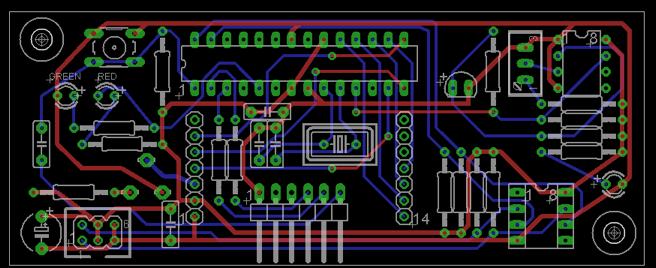
1 Lab Task 3 Soldering the PCB

2 PCB I:! Use a wire to connect the 5V to pin 7! 2
3 PCB II 3
4 PCB Circuit design!! R17 = 25k!!!! R9 = 47k!! 4
5 Soldering

6 PCB I Step1: Power Supply uc C1 LED3 C6 R4 6 C5 1 Connector Components: R4 = 1k C5 = 1uF C1 = C6 = 100nF LED3 = LED Green Connector: GND = Pin 3,4 5V = Pin 5,6 6
7 PCB II Step1: Power Supply Connector uc C1 R4 C5 6 LED3 1 Connector C6 Components: R4 = 1k C5 = 1uF C1 = C6 = 100nF LED3 = LED Green/Yellow Connector: GND = Pin 5,6 5V = Pin 3,4 7
8 PCB I Step1: Powersupply Testcase 1: When you finish step 1 with soldering, call the staff! Connect the 5V and Ground to your PCB-Board. à Result: the Power LED (led3) lights up. 8
9 PCB I Step2: Programming uc LED2 LED1 + R1 Reset + R11 R10 Switching the LED1/2 = gpio3 C3 C4 Q1 R3 R2 C2 Connector2 GND Connector2: GND = Pin 1 Tx = Pin 4 Rx= Pin 5 DTR= Pin 6 Connection DTR: R1 = 10k C2 = 100nF Resetbutton Connection Tx, Rx: R2 = R3 = 1k Components: LED1 = Red LED2 = Green R10 = R11 = 330 uc: Q1 = 16MHz C3 = C4 = 22p 9
10 PCB II Step2: Programming uc Reset C2 + + LED2 LED1 R11 R10 R1 Switching the LED1/2 = gpio3 R3 R2 C3 C4 Q1 GND Connector2 Connector2: GND = Pin 1 Tx = Pin 4 Rx= Pin 5 DTR= Pin 6 Connection DTR: R1 = 10k C2 = 100nF Resetbutton Connection Tx, Rx: R2 = R3 = 1k Components: LED1 = Red LED2 = Green R10 = R11 = 330 uc: Q1 = 16MHz C3 = C4 = 22p 10
11 PCB I Step2: Programming uc Testcase 2: When you finish Step 2 with soldering, call the staff! Connect the uc with the FTDI and connect the FTDI to the PC Open the blinking LED Program and use the GPIO 3 as the output signal. Upload the blinking LED Program. àresult: the green and the red LED light up alternately. 11
12 PCB I Step3: Comparator R15 R14 R13 R12 Connection To Comparator Output D1 R16 IC3 Connection Comparator: IC3 = LM311 R12 = 4,7M D1 = SFH205 R13 = 3,3k R14 = 4,7k R15 = 10k = Trimmer R16 = 1M Comments: Comparator Outputsignal is connected to Pin 11 of the uc 12
13 PCB II Step3: Comparator Pin11 D1 - R12 R15 IC3 R14 R13 R16 Connection Comparator: IC3 = LM311 R12 = 4,7M D1 = SFH205 R13 = 3,3k R14 = 4,7k R15 = 10k = Trimmer R16 = 1M Comments: Comparator Outputsignal is connected to Pin 11 of the uc 13
14 PCB I Step3: Comparator Testcase 3: Build up the sender on a second PCB Board. Use your PCB Board to receive the signal. Program the uc and use the Comparator Output to control the green and red LED. When the program starts, the green LED should be on and the red LED should be off. If the signal between the transmitter and the receiver is blocked, the red LED should turn on and the green led turn off. If the red LED is on, wait two seconds and turn the red LED off and turn the green LED on. TSHA 6203 R5= 100 GND Sender 14
15 PCB I Step4: Bus-Extender and LCD R7 R8 R6 R5 IC2 R17 Connection Bus-Extender: IC2 = 82B715 R5 = R6 = R7 =R8 = 4,7k Connector Pin 1 = LCL=SCL Connector Pin 2 = LDA=SDA R LCD Connector Connection between LCD and uc: LCD Pin4 = uc GIPO7 LCD Pin11 = uc GPIO10 LCD Pin5 = uc GPIO8 LCD Pin12 = uc GPIO11 LCD Pin6 = uc GPIO9 LCD Pin13 = uc GPIO12 LCD Pin14 = uc GPIO13 15 LCD Connector Connector R9 = 47k R17 = 25k (Poti)
16 PCB II Step4: Bus-Extender and LCD R17 R9 6 1 Connector LCD Connector R5 R6 R7 R8 IC2 Connection Bus-Extender: IC2 = 82B715 R5 = R6 = R7 =R8 = 4,7k Connector Pin 1 = LCL=SCL Connector Pin 2 = LDA=SDA Connection between LCD and uc: LCD Pin4 = uc GIPO7 LCD Pin11 = uc GPIO10 LCD Pin5 = uc GPIO8 LCD Pin12 = uc GPIO11 LCD Pin6 = uc GPIO9 LCD Pin13 = uc GPIO12 LCD Pin14 = uc GPIO13 16 R9 = 47k R17 = 25k (Poti)
17 PCB I Step4: Bus-Extender and LCD Testcase 4A: The 8x2 LCD display has to be operated in 4-bit mode. Make a simple program and display Test on the 8x2 LCD. Port - Config GPIO7 = RS GPIO8 = Read/Write = 1/0 GPIO9 = E = Enable GPIO10-13 = Databits for the LCD! Notice 1: There are many LCD-examples for the Arduino!! Notice 2: Set the resistor R17 for the display contrast! àresult: Display output: T E S T 17
18 PCB I Step4: Bus-Extender and LCD Testcase 4B: Connect your PCB Board with an Arduino over I2C The master sends a sign to the slave. The slave answers with the next ASCII sign. Input of the sign via keyboard of the PC. The both signs (Master and Slave) have to be displayed on the LCD Display (First row: sign of the master; second row: sign of the slave). à Result: Display output example: M A S T E R : A S L A V E : B 18
19 Last lab session
20 Last Lab Day: Presentation and Life Demonstration At the last lab day, you will have time to setup your system and implement some last adjustments. However, the final 90 minutes will be your presentations: 1. Each group will given a Pecha Kucha presentation at the beamer about the project (see next slide) 2. Each group will give a short life demonstration at the lab desk, to prove the correct functioning of their project (max. 3 minutes). Both elements are required to pass the lab. No extension of the deadline is possible, since the pre-examination marks must be submitted to the FSB. 20


21 What is Pecha Kucha Pecha Kucha 20x20 is a simple presentation format where you show 20 images and each image for 20 seconds. The images advance automatically and you talk along to the images. This means that your presentation will be exactly 6:40 minutes in total. Each slide should contain a picture or screenshot or drawing only. You can only added maximum three words on a slide More information on pecha kucha can be found here: or search the internet for examples. The fast visual presentation style hopefully is informative and fun at the same time 21
22 Required Presentation Contents Task and assumed challenge Team members and roles Work / Project plan Block Diagram (your own, no copy) Calculation, if any Oscilloscope screenshots Brief C-Code fragment (that the auditorium can grasp in 20 seconds!) Challenges encountered and solution approaches Conclusion about your work Adherence to your own work plan Conclusions on your team work Remember to use visual elements only (3 additionally printed words are allowed!) 22
RF4432 wireless transceiver module
 RF4432 wireless transceiver module 1. Description RF4432 adopts Silicon Lab Si4432 RF chip, which is a highly integrated wireless ISM band transceiver. The features of high sensitivity (-121 dbm), +20
"shell" digital storage oscilloscope (Beta)
") "shell" digital storage oscilloscope (Beta) 1. Main board: solder the element as the picture shows: 2. 1) Check the main board is normal or not Supply 9V power supply through the connector J7 (Note: The
"shell" digital storage oscilloscope (Beta) 1. Main board: solder the element as the picture shows: 2. 1) Check the main board is normal or not Supply 9V power supply through the connector J7 (Note: The
Device for a inserting text into a video-signal
 ATV-LOGO Device for a inserting text into a video-signal 1998 2000 Wolfgang Otterbach, DL1IE All rights reserved. 10/2000 General The ATV-LOGO is an inexpensive but stable device for inserting text into
RF4432F27 wireless transceiver module
 RF4432F27 wireless transceiver module 1. Description RF4432F27 is 500mW RF module embedded with amplifier and LNA circuit. High quality of component, tightened inspection and long term test make this module
MBUS 10 RS232 TO MBUS LEVEL CONVERTER
 Media and protocol converters MBUS 10 RS232 TO MBUS LEVEL CONVERTER RS232 to MBus level conversion Maximum 10 MBus slaves Baud Rate: 300 to 19200 bps RS232 MBus opto isolation Over-current and short-circuit
Be a part of the circuit. Brick'R'knowledge. Set overview.
 Be a part of the circuit. Brick'R'knowledge Set overview www.brickrknowledge.com (Rx) SDA SCL 5V GND (10:1) I2C, max 20V (Tx) GPIO0 RESET int, max 10V GND 1 5V GND 1 2 5V 5V GND 1 2 3 Brick R knowledge
E M E - Antenna Controller System - OE5JFL. Block diagram
 E M E - Antenna Controller System - OE5JFL Block diagram 1.Controller board Page 2 of 12 Short description of the features - Computation of position (without PC!) for Moon, Sun, Cassiopeia, Cygnus, Sagittarius,
Objectives: Learn how LED displays work Be able to output your name on the display
 Objectives: Learn how LED displays work Be able to output your name on the display By the end of this session: You will know how simple LED displays work and be able to make them give a useful output.
ECE 2274 Pre-Lab for Experiment Timer Chip
 ECE 2274 Pre-Lab for Experiment 6 555 Timer Chip Introduction to the 555 Timer The 555 IC is a popular chip for acting as multivibrators. Go to the web to obtain a data sheet to be turn-in with the pre-lab.
SignalTap Plus System Analyzer
 SignalTap Plus System Analyzer June 2000, ver. 1 Data Sheet Features Simultaneous internal programmable logic device (PLD) and external (board-level) logic analysis 32-channel external logic analyzer 166
Digital Clock. Perry Andrews. A Project By. Based on the PIC16F84A Micro controller. Revision C
 Digital Clock A Project By Perry Andrews Based on the PIC16F84A Micro controller. Revision C 23 rd January 2011 Contents Contents... 2 Introduction... 2 Design and Development... 3 Construction... 7 Conclusion...
SWITCH: Microcontroller Touch-switch Design & Test (Part 2)
") SWITCH: Microcontroller Touch-switch Design & Test (Part 2) 2 nd Year Electronics Lab IMPERIAL COLLEGE LONDON v2.09 Table of Contents Equipment... 2 Aims... 2 Objectives... 2 Recommended Timetable... 2
SWITCH: Microcontroller Touch-switch Design & Test (Part 2) 2 nd Year Electronics Lab IMPERIAL COLLEGE LONDON v2.09 Table of Contents Equipment... 2 Aims... 2 Objectives... 2 Recommended Timetable... 2
Reaction Game Kit MitchElectronics 2019
 Reaction Game Kit MitchElectronics 2019 www.mitchelectronics.co.uk CONTENTS Schematic 3 How It Works 4 Materials 6 Construction 8 Important Information 9 Page 2 SCHEMATIC Page 3 SCHEMATIC EXPLANATION The
E M E - Antenna Controller System - OE5JFL. Block diagram
 E M E - Antenna Controller System - OE5JFL Block diagram 1.Controller board Page 2 of 13 Short description of the features - Computation of position (without PC!) for Moon, Sun, Cassiopeia, Cygnus, Sagittarius,
DSO138mini Troubleshooting Guide
 DSO138mini Troubleshooting Guide Applicable main board: 109-13800-00I Applicable analog board: 109-13801-00H 1. Frequently Found Problems 1) LCD completely dark. No backlight 2) LCD lights up but no display
Notice technique / Technical manual NT Ind A 14/26. SONY FCB H11 and FCB EH4300 SDI Interface module. Technical manual
 Notice technique / Technical manual NT10 0301 Ind A 14/26 SONY FCB H11 and FCB EH4300 SDI Interface module Technical manual Notice technique / Technical manual NT10 0301 Ind A 15/26 Sommaire 1 Presentation...
USER MANUAL HDMI over IP EXTENDER
 USER MANUAL HDMI over IP EXTENDER Introduction: The HDMIRHRX101120M is a sophisticated many to many HDMI over IP extender. HDCP 2.0 compliant and resolutions up to 1080P full HD and 1920x1200 (WUXGA) are
ET-REMOTE DISTANCE. Manual of ET-REMOTE DISTANCE
 ET-REMOTE DISTANCE ET-REMOTE DISTANCE is Distance Measurement Module by Ultrasonic Waves; it consists of 2 important parts. Firstly, it is the part of Board Ultrasonic (HC-SR04) that includes sender and
VU Meter Buffer DIY Kit
 VU Meter Buffer DIY Kit Warning This document is distributed for educational purposes only. This equipment operates at potentially lethal voltages. Only trained, qualified personnel should operate, maintain,
SPI Serial Communication and Nokia 5110 LCD Screen
 8 SPI Serial Communication and Nokia 5110 LCD Screen 8.1 Objectives: Many devices use Serial Communication to communicate with each other. The advantage of serial communication is that it uses relatively
Callisto DISEqC Antenna Tracker
 Callisto DISEqC Antenna Tracker Figure 1: Final product Description The goal of the project was to make an antenna tracker that could not only follow the sun, but also other objects in the sky (moon, Satellite,
Introduction to Serial I/O
 CS/ECE 6780/5780 Al Davis Serial I/O Today s topics: general concepts in preparation for Lab 8 1 CS 5780 Introduction to Serial I/O 2 CS 5780 Page 1 A Serial Channel 3 CS 5780 Definitions 4 CS 5780 Page
Page 1. Introduction to Serial I/O. Definitions. A Serial Channel CS/ECE 6780/5780. Al Davis. Today s topics: Serial I/O
 Introduction to Serial I/O CS/ECE 6780/5780 Al Davis Serial I/O Today s topics: general concepts in preparation for Lab 8 1 CS 5780 2 CS 5780 A Serial Channel Definitions 3 CS 5780 4 CS 5780 Page 1 Bandwidth
Total solder points: 123 Difficulty level: beginner 1. advanced AUDIO ANALYZER K8098. audio gea Give your. . high-tech ILLUSTRATED ASSEMBLY MANUAL
 Total solder points: 123 Difficulty level: beginner 1 2 3 4 5 advanced AUDIO ANALYZER K8098 ra audio gea Give your. look high-tech ILLUSTRATED ASSEMBLY MANUAL H8098IP-1 Features & Specifications Features
Experiment 8 Fall 2012
 10/30/12 Experiment 8 Fall 2012 Experiment 8 Fall 2012 Count UP/DOWN Timer Using The SPI Subsystem and LCD Display NOTE: Late work will be severely penalized - (-7 points per day starting directly at the
TV Character Generator
 TV Character Generator TV CHARACTER GENERATOR There are many ways to show the results of a microcontroller process in a visual manner, ranging from very simple and cheap, such as lighting an LED, to much
Building the ChronoDot Calendar Reminder
 Building the ChronoDot Calendar Reminder Being very forgetful and married is not a good combination. Luckily my wife comes up with solutions and suggested that we make some sort of reminder that would
Laboratory 4. Figure 1: Serdes Transceiver
 Laboratory 4 The purpose of this laboratory exercise is to design a digital Serdes In the first part of the lab, you will design all the required subblocks for the digital Serdes and simulate them In part
Experiment 7 Fall 2012
 10/30/12 Experiment 7 Fall 2012 Experiment 7 Fall 2012 Count UP/DOWN Timer Using The SPI Subsystem Due: Week 9 lab Sessions (10/23/2012) Design and implement a one second interval (and high speed 0.05
Part 2 -- A digital thermometer or talk I2C to your atmel microcontroller
 Home Electronics Graphics, Film & Animation E-cards Other Linux stuff Photos Online-Shop Content: The new things The LCD display A little GUI How it works: Analog to digital conversion How it works: I2C
Design and Implementation of an AHB VGA Peripheral
 Design and Implementation of an AHB VGA Peripheral 1 Module Overview Learn about VGA interface; Design and implement an AHB VGA peripheral; Program the peripheral using assembly; Lab Demonstration. System
ANTUMBRA FADE MANUAL
 ANTUMBRA FADE MANUAL TABLE OF CONTENTS 01. INSTALLATION 4 02. BACK 5 03. FRONT 6 04. USE 7 05. LINK 8 06. BILL OF MATERIALS 9 07. BUILD NOTES 10 08. BACK 11 09. FRONT 14 10. MODIFICATION 15 11. FINISHED
MSP430 JTAG / BSL connectors
 MSP430 JTAG / BSL connectors (PD010A05 Rev-4: 23-Nov-2007) FAQ: Q: I have a board with the standard TI-JTAG pinhead. Can I use your programmer to flash my MSP430Fxx device? A: Yes. You can use any of our
Manual PVA 4307, PVA 4310, PVA 4316 Video conferencing loudspeaker
 Manual PVA 4307, PVA 4310, PVA 4316 Video conferencing loudspeaker Video conferencing loudspeaker with RS 232/485 communication The PVA 4307, PVA 4310, PVA 4316 loudspeaker is especially designed for video
Measurement of Modulation Spectrum on GSM/DCS/PCS Mobiles acc. to GSM
 Measurement of Modulation Spectrum on GSM/DCS/PCS Mobiles acc. to GSM.0- Application Note MA0_E Subject to change Roland Minihold 98-0 Products: Application Firmware FSE-K0 Spectrum Analyzer FSE + FSE-B7
Digital 1 Final Project Sequential Digital System - Slot Machine
 Digital 1 Final Project Sequential Digital System - Slot Machine Joseph Messner Thomas Soistmann Alexander Dillman I. Introduction The purpose of this lab is to create a circuit that would represent the
Rfid Based Attendance System
 Rfid Based Attendance System Raj Kumar Mistri 1, Kamlesh Kishore 2, Priyanka Nidhi 3, Pushpakumari 4, Vikrantkumar 5 1, 2 Assistant Professor, 3,4,5 B.Tech Scholar 1,2,3,4,5 Dept. of ECE, RTC Institute
XTAL Bank DDS Version 0.02 Sept Preliminary, highly likely to contain numerous errors
 XTAL Bank DDS Version 002 Sept 7 2012 Preliminary, highly likely to contain numerous errors The photo above shows the fully assembled Xtal Bank DDS with 2 DDS modules installed (The kit is normally only
Character LCDs. Created by lady ada. Last updated on :47:43 AM UTC
 Character LCDs Created by lady ada Last updated on 2017-12-16 12:47:43 AM UTC Guide Contents Guide Contents Overview Character vs. Graphical LCDs LCD Varieties Wiring a Character LCD Installing the Header
Measure the value of water flow using water flow sensor and DC water pump 12 V interfacing with Arduino uno
 1 2 Measure the value of water flow using water flow sensor and DC water pump 12 V interfacing with Arduino uno A flow sensor is a device for sensing the rate of fluid flow. Typically a flow sensor is
Kramer Electronics, Ltd. USER MANUAL. Models: VS-162AV, 16x16 Audio-Video Matrix Switcher VS-162AVRCA, 16x16 Audio-Video Matrix Switcher
 Kramer Electronics, Ltd. USER MANUAL Models: VS-162AV, 16x16 Audio-Video Matrix Switcher VS-162AVRCA, 16x16 Audio-Video Matrix Switcher Contents Contents 1 Introduction 1 2 Getting Started 1 3 Overview
DM1624, DM1612, DM812
 Installation Guide Hardware and Software DM Series Digital Processors models DM1624, DM1612, DM812 LECTROSONICS, INC. 1 Installation Specific Information Only This guide covers only installation related
Bill of Materials: 7-Segment LED Die with Arduino PART NO
 7-Segment LED Die with Arduino PART NO. 2190194 This project is based on the Arduino environment so that you can manipulate a die with a simple common anode 7-segment LED, a transistor PNP-2N3906, 10 resistors
USER'S MANUAL. Getting started with ALEXAN ATMEL AT89C2051/AT89C4051 Training Module - 1
 USER'S MANUAL Getting started with ALEXAN ATMEL AT89C05/AT89C405 Training Module - Version.0 Copyright 006 Ace Electronic Technology Inc. All Rights Reserved Alexan 05/405 TM- v..0 Page of 7 About This
WEIGHING INDICATOR SERIE IPE 50
 WEIGHING INDICATOR SERIE IPE 50 Short guide for calibration only see user manual 1/2 for the different functioning mode, analog output and setpoints See user manual 2/2 for special functioning mode and
uresearch GRAVITECH.US GRAVITECH GROUP Copyright 2007 MicroResearch GRAVITECH GROUP
 GRAVITECH.US uresearch GRAVITECH GROUP Description The I2C-7SEG board is a 5-pin CMOS device that provides 4-digit of 7-segment display using I 2 C bus. There are no external components required. Only
EDUCATIONAL TUTOR FOR MENTALLY DISABLE STUDENTS
 EDUCATIONAL TUTOR FOR MENTALLY DISABLE STUDENTS Shailaja Patil Assistant Professor, Rajarambapu Institute of Technology, Islampur Email: shaila.nalawade@ritindia.edu ABSTRACT Educational Tutor for mentally
DiD. LCD Video Monitor & Video Wall Universal User Manual. Digital Information Display
 LCD Video Monitor & Video Wall Universal User Manual DiD Digital Information Display Video Monitor Models M82S1/M70S1/M65S1/M55S1/M46S1/M40S1/M32S1/M24S1/M19S2/M19S1 Video Wall Models PD55N3/PD46N4/PD46N3/PD46N2/PD40N2
MONITOR POWER Shiloh Road Alpharetta, Georgia (770) FAX (770) Toll Free
 FAX (770) Toll Free") Instruction Manual Model 2099-10xx 10MHz Frequency Source April 2014, Rev. H MENU INTERNAL LEVEL = +10dBm MONITOR POWER 1 2 MODEL 2099 FREQUENCY SOURCE CROSS TECHNOLOGIES INC. ALARM OVEN REMOTE EXECUTE
Instruction Manual Model 2099-10xx 10MHz Frequency Source April 2014, Rev. H MENU INTERNAL LEVEL = +10dBm MONITOR POWER 1 2 MODEL 2099 FREQUENCY SOURCE CROSS TECHNOLOGIES INC. ALARM OVEN REMOTE EXECUTE
DRV050-VGA-R02 Drive Board User manual Ver 1.1
 Documnt Number:DDS-13-019 DRV050-VGA-R02 Drive Board User manual Ver 1.1 For Products: SVGA050/060 SC - Full Color SVGA050/060 SW - Monochrome White SVGA050/060 SG - Monochrome Green Yunnan North OLiGHTEK
3G HDSDI interface board for SONY FCB HD cameras. Technical manual
 3G HDSDI interface board for SONY FCB HD cameras Technical manual Revision History Date Modifications Pages Oct, 9th, 2013 Original All 1 Board description This board provides a 3G HDSDI output for FCB
Hardware Guide BrightSign, LLC Version:.1 Los Gatos, CA, USA. MODELS: XD Product Line
 Hardware Guide BrightSign, LLC Version:.1 Los Gatos, CA, USA MODELS: XD Product Line Contents Overview... 1 Block Diagram... 2 Ports... 2 XD230... 2 XD1030... 2 XD1230... 3 Power Connector... 3 Ethernet...
Practical De-embedding for Gigabit fixture. Ben Chia Senior Signal Integrity Consultant 5/17/2011
 Practical De-embedding for Gigabit fixture Ben Chia Senior Signal Integrity Consultant 5/17/2011 Topics Why De-Embedding/Embedding? De-embedding in Time Domain De-embedding in Frequency Domain De-embedding
LinTronic. BeoSystem control of non-b&o TV, screen or projector CINEMA MODE. Updated: BeoSystem control of non-b&o TV, screen or projector
 LinTronic BeoSystem control of non-b&o TV, screen or projector CINEMA MODE Updated: 190108 IR-Tx IR-Tx IR-Rx IR-Tx The TT455-RT-238 can be your gateway to utilizing the potential of CINEMA control from
N3ZI Digital Dial Manual For kit with Backlit LCD Rev 4.00 Jan 2013 PCB
 N3ZI Digital Dial Manual For kit with Backlit LCD Rev 4.00 Jan 2013 PCB Kit Components Item Qty Designator Part Color/Marking PCB 1 LCD Display 1 LCD 1602 Volt Regulator 1 U1 78L05, Black TO-92 Prescaler
Step What to do Expected result What to do if test fails Component tested 1 Visual inspection. Board is accurately assembled
 Fox Delta Amateur Radio Projects & Kits AAZ-0914A 50MHZ Antenna Analyzer Testing Guide by Tony / I2TZK SWR Analyzer 4 steps for a quick test Step What to do Expected result What to do if test fails Component
CC-PC Gluecard Application and User's Guide
 CC-PC Gluecard Application and User's Guide LHCb Technical Note Issue: Public Revision: 1.0 / LPHE 2005-010 Created: 25 June 2003 Last modified: 1 April 2004 Prepared By: Flavio Fontanelli, Beat Jost,
Checkpoint 2 Video Interface
 University of California at Berkeley College of Engineering Department of Electrical Engineering and Computer Sciences EECS150 Fall 1998 R. Fearing and Kevin Cho 1. Objective Checkpoint 2 Video Interface
IS01BFRGB LCD SmartDisplay from NKK Switches Simple implementation featuring the ATmega88PA from Atmel Complete software solution
 DKAN0003A Controlling the SmartDisplay with a SPI Peripheral 09 June 009 Features IS01BFRGB LCD SmartDisplay from NKK Switches Simple implementation featuring the ATmega88PA from Atmel Complete software
Part No. ENC-LAB01 Users Manual Introduction EncoderLAB
 PCA Incremental Encoder Laboratory For Testing and Simulating Incremental Encoder signals Part No. ENC-LAB01 Users Manual The Encoder Laboratory combines into the one housing and updates two separate encoder
O P E R A T I O N M A N U A L. RF-Reader. Stand-alone-Reader Leser 2plus with RS-232 interface
 O P E R A T I O N M A N U A L Version 01/05 RF-Reader Stand-alone-Reader Leser 2plus with RS-232 interface Important! Read by all means! To maintain the perfect shipping conditions and to ensure safe operation
8 PIN PIC PROGRAMMABLE BOARD (DEVELOPMENT BOARD & PROJECT BOARD)
") ESSENTIAL INFORMATION BUILD INSTRUCTIONS CHECKING YOUR PCB & FAULT-FINDING MECHANICAL DETAILS HOW THE KIT WORKS LEARN ABOUT PROGRAMMING WITH THIS 8 PIN PIC PROGRAMMABLE BOARD (DEVELOPMENT BOARD & PROJECT
ESSENTIAL INFORMATION BUILD INSTRUCTIONS CHECKING YOUR PCB & FAULT-FINDING MECHANICAL DETAILS HOW THE KIT WORKS LEARN ABOUT PROGRAMMING WITH THIS 8 PIN PIC PROGRAMMABLE BOARD (DEVELOPMENT BOARD & PROJECT
Mal-2 assembly guide v1.0
 Mal-2 assembly guide v.0 SONIC POTIONS Schematic and BOM The BOM can be found on Google Docs Prepare the PCB Separate the PCBs using some pliers. PCB We start with the lower PCB and assemble it beginning
502DAC Digital Pro Audio Hat Hardware Reference Manual 2017 PI 2 Design
 Pi 2 Media 502DAC Digital Pro Audio Hat Hardware Reference Manual 2017 PI 2 Design PAGE 1 Table of Contents 1 Warranty... 3 2 Operating Specifications... 4 2.1 502DAC Operating specifications... 4 3 Overview...
DIY KIT MHZ 8-DIGIT FREQUENCY METER
 This kit is a stand-alone frequency meter capable of measuring repetitive signals up to a frequency of 50MHz. It has two frequency ranges (15 and 50 MHz) as well as two sampling rates (0.1 and 1 second).
How to overcome/avoid High Frequency Effects on Debug Interfaces Trace Port Design Guidelines
 How to overcome/avoid High Frequency Effects on Debug Interfaces Trace Port Design Guidelines An On-Chip Debugger/Analyzer (OCD) like isystem s ic5000 (Figure 1) acts as a link to the target hardware by
L, LTC, LTM, LT are registered trademarks of Linear Technology Corporation. Other product
 DESCRIPTION WARNING! Do not look directly at operating LED. This circuit produces light that can damage eyes. Demo Circuit 1265 QUICK START GUIDE LTC3220/LTC3220-1 360mA Universal 18-Channel LED Driver
ATA8520D Production and EOL Testing. Features. Description ATAN0136 APPLICATION NOTE
 ATAN0136 ATA8520D Production and EOL Testing APPLICATION NOTE Features Test application for production and EOL testing of ATA8520-EK1-E/ EK2-E/ EK3-E evaluation kits PCB component tests, i.e., MCU, temperature
IS01BFRGB LCD SmartDisplay from NKK Switches Low cost implementation featuring the ATtiny13A from Atmel Complete software solution
 DKAN0002A Bit-banging the SmartDisplay 09 June 2009 Features IS01BFRGB LCD SmartDisplay from NKK Switches Low cost implementation featuring the ATtiny13A from Atmel Complete software solution Introduction
Serial Remote Control of the RX2 SERIAL REMOTE CONTROL FOR THE RX2
 SERIAL REMOTE CONTROL FOR THE RX2 Version 2.0 1 May 2005 RIG Updated May 2005 to support NOAA-18 Version 2.0 2 May 2005 Introduction Some years ago, Max Hadley published an article detailing how enthusiasts
DEM B SBH-PW-N (A-TOUCH)
") DISPLAY Elektronik GmbH LCD MODULE DEM 128128B SBH-PW-N (A-TOUCH) Version :2 28/Dec/2007 GENERAL SPECIFICATION MODULE NO. : DEM 128128B SBH-PW-N (A-TOUCH) CUSTOMER P/N VERSION NO. CHANGE DESCRIPTION DATE
DISPLAY Elektronik GmbH LCD MODULE DEM 128128B SBH-PW-N (A-TOUCH) Version :2 28/Dec/2007 GENERAL SPECIFICATION MODULE NO. : DEM 128128B SBH-PW-N (A-TOUCH) CUSTOMER P/N VERSION NO. CHANGE DESCRIPTION DATE
N3ZI Digital Dial Manual For kit with Serial LCD Rev 3.04 Aug 2012
 N3ZI Digital Dial Manual For kit with Serial LCD Rev 3.04 Aug 2012 Kit properly assembled and configured for Standard Serial LCD (LCD Not yet connected) Kit Components Item Qty Designator Part Color/Marking
DE2-115/FGPA README. 1. Running the DE2-115 for basic operation. 2. The code/project files. Project Files
 DE2-115/FGPA README For questions email: jeff.nicholls.63@gmail.com (do not hesitate!) This document serves the purpose of providing additional information to anyone interested in operating the DE2-115
Ten-Tec (865) Service Department:(865)
 Service Department:(865)") Ten-Tec (865) 453-7172 Service Department:(865) 428-0364 Installation Instructions for Ten-Tec Jupiter AT538K Tuner Kit The installation of the AT538K is divided into two steps. The first step is to reprogram
Ten-Tec (865) 453-7172 Service Department:(865) 428-0364 Installation Instructions for Ten-Tec Jupiter AT538K Tuner Kit The installation of the AT538K is divided into two steps. The first step is to reprogram
SquareLED - Aura Bar & Matrix Beam Light 100
 SquareLED - Aura Bar & Matrix Beam Light 100 1. SAFETY INSTRUCTIONS Please read these instructions carefully they include the important information about the installation usage and maintenance of this
Arduino Hacking Village THOTCON 0x9
 Arduino Hacking Village THOTCON 0x9 Logic Analyzer Lab Use a Logic Analyzer to inspect common embedded system protocols Lab time: 5-20 minutes Overview Embedded systems use a variety of protocols to communicate
Lab #10: Building Output Ports with the 6811
 1 Tiffany Q. Liu April 11, 2011 CSC 270 Lab #10 Lab #10: Building Output Ports with the 6811 Introduction The purpose of this lab was to build a 1-bit as well as a 2-bit output port with the 6811 training
IOCard Displays II Manual. Date:08/03/17 Rev.:2.3
 Date:08/03/17 Rev.:2.3 Index: IOCARD DISPLAYS II MANUAL... 1 INDEX:... 2 INTRODUCTION:... 3 DISPLAYS II:... 3 Components and outline:... 3 Connector's description:... 4 INPUTS:... 4 Displays direct to
Configuration Vestas VMP3500
 Configuration Vestas VMP3500 1. Table of contents 1. Table of contents... 2 2. Introduction... 3 3. Vestas turbines (RCS)... 4 3.1. VMP 3500 controller... 4 3.2. Communication with the CT3230 current loop
FPGA-BASED EDUCATIONAL LAB PLATFORM
 FPGA-BASED EDUCATIONAL LAB PLATFORM Mircea Alexandru DABÂCAN, Clint COLE Mircea Dabâcan is with Technical University of Cluj-Napoca, Electronics and Telecommunications Faculty, Applied Electronics Department,
ImproX (TRT) Twin Remote Terminal
 Twin Remote Terminal") www.powelltronics.com ImproX TRT ImproX (TRT) Twin Remote Terminal Overview Introduction The ImproX (TRT) Twin Remote Terminal is a reader interface Terminal. The ImproX TRT is designed to interface with
www.powelltronics.com ImproX TRT ImproX (TRT) Twin Remote Terminal Overview Introduction The ImproX (TRT) Twin Remote Terminal is a reader interface Terminal. The ImproX TRT is designed to interface with
NON-OVERSAMPLING DIGITAL TO ANALOG CONVERTER ASSEMBLY INSTRUCTIONS FEATURES DESCRIPTION JUNDAC FIVE
 NON-OVERSAMPLING DIGITAL TO ANALOG CONVERTER ASSEMBLY INSTRUCTIONS July 2011 - Rev 1.0, Eric Juaneda - www.junilabs.com FEATURES ONE DIGITAL INPUT S/PDIF, AES3 DIGITAL TRANSFORMER INPUT RCA, BNC or XLR
FRQM-2 Frequency Counter & RF Multimeter
 FRQM-2 Frequency Counter & RF Multimeter Usage Instructions Firmware v2.09 Copyright 2007-2011 by ASPiSYS Ltd. Distributed by: ASPiSYS Ltd. P.O.Box 14386, Athens 11510 (http://www.aspisys.com) Tel. (+30)
Bill of Materials: Super Simple Water Level Control PART NO
 Super Simple Water Level Control PART NO. 2169109 Design a simple water controller in which electrodes are required to sense high and low water levels in a tank. Whenever the water level falls below the
Universal DiSEqC controller USER MANUAL
 Universal USER MANUAL SAT CONTROL 1. INTRODUCTION Satellite television is one of most favourite and popular medium in today s world. But reception 36.000 km away from the sky is more technically difficult.
Universal DiSEqC controller USER MANUAL SAT CONTROL
 USER MANUAL SAT CONTROL SAT CONTROL Dear customer, If you have not been able to put the system into operation or have problems installing it, call the Technical Assistance phone as indicated on the first
9 Analyzing Digital Sources and Cables
 9 Analyzing Digital Sources and Cables Topics in this chapter: Getting started Measuring timing of video signal Testing cables and distribution systems Testing video signal quality from a source Testing
Dual HD-SDI Output (MCX + BNC connector) HD- SDI Cable Driver. HDMI DVI Tx connector. Optical HD- SDI Output LC - connector. 8pin
 HD- SDI Cable Driver. HDMI DVI Tx connector. Optical HD- SDI Output LC - connector. 8pin") Thunder Link is a family of small form factor modules for formatting and converting generic digital video streams to standard compliant formats. Different interface standards are supported from the transmitter
Thunder Link is a family of small form factor modules for formatting and converting generic digital video streams to standard compliant formats. Different interface standards are supported from the transmitter
DDS VFO CONSTRUCTION MANUAL. DDS VFO Construction Manual Issue 1.1 Page 1
 DDS VFO CONSTRUCTION MANUAL DDS VFO Construction Manual Issue 1.1 Page 1 Important Please read before starting assembly STATIC PRECAUTION The DDS VFO kit contains the following components which can be
C ch optical MADI & AoIP I/O. MASTER mode: A C8000 frame may be clocked via MADI input or AES67 network. AoIP Dante Brooklin II OEM module
 features Interface for AoIP (AES67 or DANTE) Two AoIP network ports for redundant or switch operation MADI I/O connection Optical SFP module / LC connectors (multi mode or single mode fiber) BNC parallel
Aegis Electronic Group
 This is a family of small form factor modules for formatting and converting generic digital video streams to standard compliant formats. Different interface standards are supported from the transmitter
imso-104 Manual Revised August 5, 2011
 imso-104 Manual Revised August 5, 2011 Section 1 Getting Started SAFETY 1.10 Quickstart Guide 1.20 SAFETY 1.30 Compatibility 1.31 Hardware 1.32 Software Section 2 How it works 2.10 Menus 2.20 Analog Channel
Features. = +25 C, LO = 0 dbm, Vcc = Vcc1, 2, 3 = +5V, G_Bias = +2.5V *
 Typical Applications The is Ideal for: Cellular/3G & LTE/WiMAX/4G Basestations & Repeaters GSM, CDMA & OFDM Transmitters and Receivers Features High Input IP3: +38 dbm 8 db Conversion Loss @ 0 dbm LO Optimized
AD9884A Evaluation Kit Documentation
 a (centimeters) AD9884A Evaluation Kit Documentation Includes Documentation for: - AD9884A Evaluation Board - SXGA Panel Driver Board Rev 0 1/4/2000 Evaluation Board Documentation For the AD9884A Purpose
The Serial Port is Dead! Long Live the Serial Port! USB Serial Port Breadboard Experiments with the FTDI FT232R
 The Serial Port is Dead! Long Live the Serial Port! USB Serial Port Breadboard Experiments with the FTDI FT232R Copyright Joe Pardue 2008. This material was previously published in the June 2008 issue
Lab #5: Design Example: Keypad Scanner and Encoder - Part 1 (120 pts)
") Nate Pihlstrom, npihlstr@uccs.edu Lab #5: Design Example: Keypad Scanner and Encoder - Part 1 (120 pts) Objective The objective of lab assignments 5 through 9 are to systematically design and implement
Nate Pihlstrom, npihlstr@uccs.edu Lab #5: Design Example: Keypad Scanner and Encoder - Part 1 (120 pts) Objective The objective of lab assignments 5 through 9 are to systematically design and implement
GENESIS RADIO CALIBRATION PROCEDURES
 GENESIS RADIO CALIBRATION PROCEDURES covering all G59 models and GPA10 power amplifier Si570 frequency adjustment Si570 Frequency calibration This is a very straightforward and easy operation! 1- Set up
MAX2660/MAX2661/MAX2663/MAX2671 Evaluation Kits
 9-382; Rev ; 9/99 MAX2660/MAX266/MAX2663/MAX267 General Description The MAX2660/MAX266/MAX2663/MAX267 evaluation kits simplify evaluation of the MAX2660/MAX266/ MAX2663/MAX267 upconverter s. They enable
10MHz Source/Inserter
 Instruction Manual Model 2099-218 10MHz Source/Inserter Redundant 18V January 2011, Rev. A RX 0.32 A TX 0.86 A REF ON REF OFF MENU MODEL 2099 SOURCE/INSERTER CROSS TECHNOLOGIES INC. PS1 PS2 REMOTE ALARM
Troubleshooting. 1. Symptom: Status indicator (Red LED) on SSR is constant on. 2. Symptom: Output indicator (Yellow LED) on SSR is flashing.
 on SSR is constant on. 2. Symptom: Output indicator (Yellow LED) on SSR is flashing.") Product Data Electrical Data SST (Transmitter) SSR (Receiver) Supply voltage 18 30 V dc Max. Voltage ripple 15 % (within supply range) Current consumption 100 ma (RMS) 75 ma Digital - 100 ma Max. outputs
Product Data Electrical Data SST (Transmitter) SSR (Receiver) Supply voltage 18 30 V dc Max. Voltage ripple 15 % (within supply range) Current consumption 100 ma (RMS) 75 ma Digital - 100 ma Max. outputs