LIVE SOUND SUBWOOFER DR. ADAM J. HILL COLLEGE OF ENGINEERING & TECHNOLOGY, UNIVERSITY OF DERBY, UK GAND CONCERT SOUND, CHICAGO, USA 20 OCTOBER 2017
|
|
|
- Eustacia Gibbs
- 6 years ago
- Views:
Transcription
1 LIVE SOUND SUBWOOFER SYSTEM DESIGN DR. ADAM J. HILL COLLEGE OF ENGINEERING & TECHNOLOGY, UNIVERSITY OF DERBY, UK GAND CONCERT SOUND, CHICAGO, USA 20 OCTOBER 2017

2 GOALS + CHALLENGES SINGLE SUBWOOFERS SUBWOOFER CLUSTERS HORIZONTAL ARRAYS VERTICAL ARRAYS SIGNAL PROCESSING TECHNIQUES PERCEPTUAL CONSIDERATIONS RECOMMENDATIONS
3 GOALS + CHALLENGES SINGLE SUBWOOFERS SUBWOOFER CLUSTERS HORIZONTAL ARRAYS VERTICAL ARRAYS SIGNAL PROCESSING TECHNIQUES PERCEPTUAL CONSIDERATIONS RECOMMENDATIONS
![GOALS + CHALLENGES [01/19] COMMON](/docs-images/77/75616926/images/4-0.jpg "ISSUES Inconsistent audience coverage")

4 GOALS + CHALLENGES [01/19] COMMON ISSUES Inconsistent audience coverage Excessive sound energy outside audience area Smeared transients, muddy sounding system
![GOALS + CHALLENGES [02/19] COMMON CHALLENGES Truck space](/docs-images/77/75616926/images/5-0.jpg "Budget Sight lines Venue capabilities Power distribution")
5 GOALS + CHALLENGES [02/19] COMMON CHALLENGES Truck space Budget Sight lines Venue capabilities Power distribution Time!
![GOALS + CHALLENGES [03/19] TYPICAL GOALS Consistent audience coverage](/docs-images/77/75616926/images/6-0.jpg "Minimal energy outside audience area Sharp transient response, high quality")
6 GOALS + CHALLENGES [03/19] TYPICAL GOALS Consistent audience coverage Minimal energy outside audience area Sharp transient response, high quality sound
![GOALS + CHALLENGES [04/19] ROOM-MODES These often come up in discussions with](/docs-images/77/75616926/images/7-0.jpg "engineers Some questions: 1. What are room-modes? 2.")
7 GOALS + CHALLENGES [04/19] ROOM-MODES These often come up in discussions with engineers Some questions: 1. What are room-modes? 2. Are room-modes an issue in live sound?
![GOALS + CHALLENGES [05/19] ROOM-MODES 1. What are room-modes?](/docs-images/77/75616926/images/8-0.jpg "Frequencies with integer multiples of ½ wavelength fit perfectly within one or more room dimension Results in a")
8 GOALS + CHALLENGES [05/19] ROOM-MODES 1. What are room-modes? Frequencies with integer multiples of ½ wavelength fit perfectly within one or more room dimension Results in a standing wave pattern Position-dependent listening experience
9 GOALS + CHALLENGES [06/19] AXIAL TANGENTIAL OBLIQUE
10 ROOM-MODES Theoretical room-mode frequencies calculated based on room dimensions, modal indices and speed of sound = z z y y x x m L L L c f η η η GOALS + CHALLENGES [07/19]

 GOALS +")
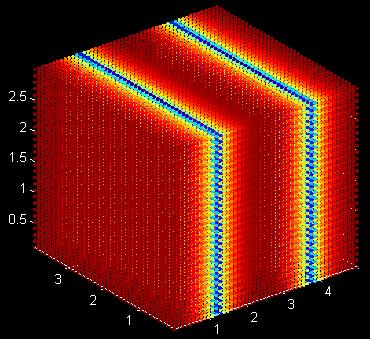
11 ROOM-MODES = z z y y x x m L L L c f η η η 5 M X 4 M X 3 M ROOM (10% ABSORPTION) GOALS + CHALLENGES [08/19]
12 GOALS + CHALLENGES [09/19] ROOM-MODES 2. Are room-modes an issue in live sound? Must define the modal region of a venue (where roommodes are perceptible) Conservatively defined using the Schroeder frequency RT 60 f s = 2000 V
13 GOALS + CHALLENGES [10/19] ROOM-MODES Medium venue (V = 8000 m 3, RT 60 = 1.5 s) Room-mode issues below 27.4 Hz Large venue(v = m 3, RT 60 = 2.5 s) Room-mode issues below 20.0 Hz Sports arena (V = m 3, RT 60 = 6.0 s) Room-mode issues below 4.0 Hz
14 GOALS + CHALLENGES [11/19] ROOM-MODES Subwoofer band typically Hz (but often subwoofers are crossed over around Hz) With room-mode problems generally outside the subwoofer range, are they causing significant issues? Not likely comb-filtering between coherent sources + reflections is a more likely culprit
![GOALS + CHALLENGES [12/19] COMB-FILTERING Principle of superposition Assumes two (or](/docs-images/77/75616926/images/15-0.jpg "more) sources being combined are directly related to one another Called correlated")
15 GOALS + CHALLENGES [12/19] COMB-FILTERING Principle of superposition Assumes two (or more) sources being combined are directly related to one another Called correlated addition
![GOALS + CHALLENGES [13/19] COMB-FILTERING If two sine waves are exactly in-phase, then](/docs-images/77/75616926/images/16-0.jpg "the resulting waveform will be twice as large as the originals (constructive")
16 GOALS + CHALLENGES [13/19] COMB-FILTERING If two sine waves are exactly in-phase, then the resulting waveform will be twice as large as the originals (constructive interference)
![GOALS + CHALLENGES [14/19] COMB-FILTERING If two sine waves are 180 out of phase](/docs-images/77/75616926/images/17-0.jpg "(or reverse polarity), the resulting waveform will be zero (destructive")
17 GOALS + CHALLENGES [14/19] COMB-FILTERING If two sine waves are 180 out of phase (or reverse polarity), the resulting waveform will be zero (destructive interference)
18 GOALS + CHALLENGES [15/19] COMB-FILTERING This becomes a more complicated issue looking across the entire subwoofer band:
![GOALS + CHALLENGES [16/19]](/docs-images/77/75616926/images/19-0.jpg "COMB-FILTERING Position-dependent,")

19 GOALS + CHALLENGES [16/19] COMB-FILTERING Position-dependent, causing inconsistent low-frequency responses across an audience area Can this be quantified?
20 GOALS + CHALLENGES [17/19] SPATIAL VARIANCE (SV) Measure of average seat-to-seat difference in frequency response (measured in db) SV = 1 N f f hi ( p L ( ) ( )) p p, i Lp i 1 i= f p p= 1 lo N 1 N 2
21 GOALS + CHALLENGES [18/19] MEAN OUTPUT LEVEL (MOL) It s also essential to inspect system efficiency MOL is the measure of average SPL across an audience MOL = N f 1 N p f hi i= f p= 1 lo N p L p ( p, i)
22 GOALS + CHALLENGES [19/19] LOW FREQUENCY FACTOR (LF) Used to take into account number of sources in system Results in an adjusted MOL LFF = 20log10 ( ) N S MOL (w/lff) = MOL 20log10 ( ) N S
23 GOALS + CHALLENGES SINGLE SUBWOOFERS SUBWOOFER CLUSTERS HORIZONTAL ARRAYS VERTICAL ARRAYS SIGNAL PROCESSING TECHNIQUES PERCEPTUAL CONSIDERATIONS RECOMMENDATIONS
![SINGLE SUBWOOFERS [1/6] Is it correct to assume a perfectly](/docs-images/77/75616926/images/24-0.jpg "omnidirectional response?")
24 SINGLE SUBWOOFERS [1/6] Is it correct to assume a perfectly omnidirectional response? Any deviation could impact array/cluster performance
![SINGLE SUBWOOFERS [2/6] Virtual investigation with d&b ArrayCalc + B6 subwoofer 40 HZ 63 HZ 80 HZ 100 HZ](/docs-images/77/75616926/images/25-0.jpg "Predicted sound energy coverage at 40 Hz (grid line spacing = 5m, color contours spaced at 6 db) Predicted polar")
25 SINGLE SUBWOOFERS [2/6] Virtual investigation with d&b ArrayCalc + B6 subwoofer 40 HZ 63 HZ 80 HZ 100 HZ Predicted sound energy coverage at 40 Hz (grid line spacing = 5m, color contours spaced at 6 db) Predicted polar response
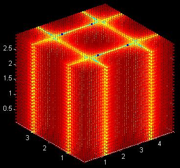
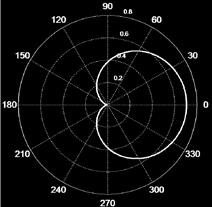
26 SINGLE SUBWOOFERS [3/6] d&b B6 subwoofer measured in hemi-anechoic chamber Speaker centered in room, measured at 2 m (30 increments) Not quite as expected why? 40 HZ 63 HZ 80 HZ 100 HZ Predicted polar response Measured polar response
![SINGLE SUBWOOFERS [4/6] Centering the speaker in the](/docs-images/77/75616926/images/27-0.jpg "room skews the polar response measurement due to the")

27 SINGLE SUBWOOFERS [4/6] Centering the speaker in the room skews the polar response measurement due to the shift in acoustic center Better to position the speaker so that the acoustic center coincides with the room center
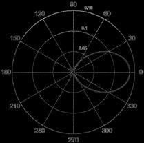
![SINGLE SUBWOOFERS [5/6] Subwoofer re-measured in hemi-anechoic chamber Acoustic center (approx.](/docs-images/77/75616926/images/28-2.jpg "37 cm) positioned at room center Results much closer to predictions!")
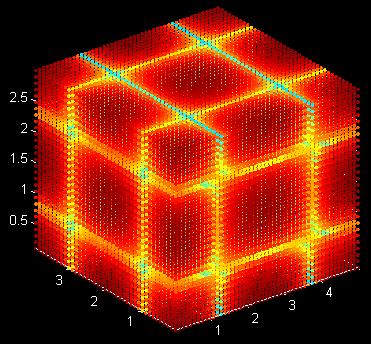
28 SINGLE SUBWOOFERS [5/6] Subwoofer re-measured in hemi-anechoic chamber Acoustic center (approx. 37 cm) positioned at room center Results much closer to predictions! 40 HZ 63 HZ 80 HZ 100 HZ Predicted polar response Measured polar response
![SINGLE SUBWOOFERS [6/6] It s essential to account for the acoustic center when measuring subwoofers!](/docs-images/77/75616926/images/29-1.jpg "Seems trivial in practice is this actually important?")
29 SINGLE SUBWOOFERS [6/6] It s essential to account for the acoustic center when measuring subwoofers! Seems trivial in practice is this actually important? 40 HZ 63 HZ 80 HZ 100 HZ Measured polar response (w/o aco ) Measured polar response (w/aco )
30 GOALS + CHALLENGES SINGLE SUBWOOFERS SUBWOOFER CLUSTERS HORIZONTAL ARRAYS VERTICAL ARRAYS SIGNAL PROCESSING TECHNIQUES PERCEPTUAL CONSIDERATIONS RECOMMENDATIONS
![SUBWOOFER CLUSTERS [01/32] Subwoofer cluster = compact arrangement](/docs-images/77/75616926/images/31-0.jpg "of multiple individual sources to achieve desired coverage pattern")
31 SUBWOOFER CLUSTERS [01/32] Subwoofer cluster = compact arrangement of multiple individual sources to achieve desired coverage pattern

![[02/32]](/docs-images/77/75616926/images/32-2.jpg "GRADIENT")
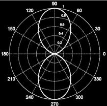
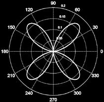
32 SUBWOOFER CLUSTERS [02/32] GRADIENT LOUDSPEAKERS Zero-order ¼ λ spacing ½ λ spacing Second-order First-order (cardioid) First-order (dipole)
33 SUBWOOFER CLUSTERS [03/32] GRADIENT LOUDSPEAKERS Physical separation + electronic delay must be correct! ¼ wavelength spacing + delay = expected polar response Deviation from this gives unwanted behavior Some examples
34 SUBWOOFER CLUSTERS [04/32] GRADIENT LOUDSPEAKERS 1 st order gradient loudspeaker Configured to 60Hz (1.43 m spacing, 4.17 ms delay) PROPERLY CONFIGURED NO POLARITY REVERSAL ½ WAVELENGTH SPACING/DELAY
35 SUBWOOFER CLUSTERS [05/32] GRADIENT LOUDSPEAKERS So gradient loudspeakers operate nicely when the physical spacing, electronic delay + polarity are correctly chosen for a specific frequency Is the resulting polar response the same for all frequencies in the subwoofer band ( Hz)? Some more examples
36 SUBWOOFER CLUSTERS [06/32] GRADIENT LOUDSPEAKERS Inconsistent low-frequency coverage Configured for 60 Hz 60 HZ 30 HZ 120 HZ
![SUBWOOFER CLUSTERS [07/32]](/docs-images/77/75616926/images/37-0.jpg "GRADIENT LOUDSPEAKERS These")

37 SUBWOOFER CLUSTERS [07/32] GRADIENT LOUDSPEAKERS These were all simulations, though Does this apply to the real world?
![SUBWOOFER CLUSTERS [08/32] GRADIENT LOUDSPEAKERS Measured in a hemi-anechoic chamber (not ideal, but 40 HZ 63 HZ 80 HZ 100 HZ still gives indication of agreement with simulations) Good results at 63](/docs-images/77/75616926/images/38-0.jpg "Hz, other bands not so good Why? # Spacing Polarity Delay 1 1.5 m Normal 0.0 ms 2 (front-tofront) Reverse 4.37 ms Front-to-rear rejection (db) Delay 40 Hz 63 Hz 80 Hz 100 Hz 4.37 ms 2.71 8.82 0.69 0.")
38 SUBWOOFER CLUSTERS [08/32] GRADIENT LOUDSPEAKERS Measured in a hemi-anechoic chamber (not ideal, but 40 HZ 63 HZ 80 HZ 100 HZ still gives indication of agreement with simulations) Good results at 63 Hz, other bands not so good Why? # Spacing Polarity Delay m Normal 0.0 ms 2 (front-tofront) Reverse 4.37 ms Front-to-rear rejection (db) Delay 40 Hz 63 Hz 80 Hz 100 Hz 4.37 ms
![SUBWOOFER CLUSTERS [09/32] GRADIENT LOUDSPEAKERS Electronic](/docs-images/77/75616926/images/39-0.jpg "delay is incorrect!")

39 SUBWOOFER CLUSTERS [09/32] GRADIENT LOUDSPEAKERS Electronic delay is incorrect! Each source s acoustic center will shift ~37 cm This adds 74 cm to the front-to-front spacing Effective source spacing now 1.5 m m = 2.24 m Delay must be set to 6.53 ms
![SUBWOOFER CLUSTERS [10/32] GRADIENT LOUDSPEAKERS Now including acoustic center shift 40 HZ 63 HZ 80 HZ 100 HZ Ideal performance predicted at 38.](/docs-images/77/75616926/images/40-0.jpg "38 Hz Results still not great Why? # Spacing Polarity Delay 1 1.5 + 0.74 m Normal 0.0 ms 2 (front-tofront) Reverse 6.")
40 SUBWOOFER CLUSTERS [10/32] GRADIENT LOUDSPEAKERS Now including acoustic center shift 40 HZ 63 HZ 80 HZ 100 HZ Ideal performance predicted at Hz Results still not great Why? # Spacing Polarity Delay m Normal 0.0 ms 2 (front-tofront) Reverse 6.53 ms Front-to-rear rejection (db) Delay 40 Hz 63 Hz 80 Hz 100 Hz 6.53 ms
41 SUBWOOFER CLUSTERS [11/32] UNIDIRECTIONAL (CARDIOID) Issue #1: Cardioid clusters require the same forward/backward moving sound energy sources facing opposite directions don t allow for this!
42 SUBWOOFER CLUSTERS [12/32] UNIDIRECTIONAL (CARDIOID) Issue #1: Cardioid clusters require the same forward/backward moving sound energy sources facing opposite directions don t allow for this! Issue #2: 40 Hz performance isn t great due to reduced source output and limitations of test environment
43 SUBWOOFER CLUSTERS [13/32] UNIDIRECTIONAL (CARDIOID) Issue #1: Cardioid clusters require the same forward/backward moving sound energy sources facing opposite directions don t allow for this! Issue #2: 40 Hz performance isn t great due to reduced source output and limitations of test environment Issue #3: 80 Hz & 100 Hz vaguely figure 8 patterns (due to ~½ wavelength spacing in this range) Orienting both sources in the forward direction and reducing the physical spacing will hopefully solve all issues
![SUBWOOFER CLUSTERS [14/32] GRADIENT LOUDSPEAKERS Ideal performance predicted at 100.](/docs-images/77/75616926/images/44-0.jpg "88 Hz 40 HZ 63 HZ 80 HZ 100 HZ No spacing compensation needed aco shifts are equal + in same direction Results seem good! Poor 40 Hz due to spacing # Spacing Polarity Delay 1 0.85 m Normal 0.")
44 SUBWOOFER CLUSTERS [14/32] GRADIENT LOUDSPEAKERS Ideal performance predicted at Hz 40 HZ 63 HZ 80 HZ 100 HZ No spacing compensation needed aco shifts are equal + in same direction Results seem good! Poor 40 Hz due to spacing # Spacing Polarity Delay m Normal 0.0 ms 2 (front-tofront) Reverse 2.48 ms Front-to-rear rejection (db) Delay 40 Hz 63 Hz 80 Hz 100 Hz 2.48 ms
![SUBWOOFER CLUSTERS [15/32] END FIRE End-fire configuration was also tested (1 st source 40 HZ 63 HZ 80 HZ 100 HZ delayed, no polarity reversal) Very similar results to gradient approach](/docs-images/77/75616926/images/45-0.jpg "Better transient response? # Spacing Polarity Delay 1 0.85 m Normal 2.48 ms 2 (front-tofront) Normal 0.0 ms Front-to-rear rejection (db) Delay 40 Hz 63 Hz 80 Hz 100 Hz 2.48 ms -2.63 3.63 10.")
45 SUBWOOFER CLUSTERS [15/32] END FIRE End-fire configuration was also tested (1 st source 40 HZ 63 HZ 80 HZ 100 HZ delayed, no polarity reversal) Very similar results to gradient approach Better transient response? # Spacing Polarity Delay m Normal 2.48 ms 2 (front-tofront) Normal 0.0 ms Front-to-rear rejection (db) Delay 40 Hz 63 Hz 80 Hz 100 Hz 2.48 ms
46 SUBWOOFER CLUSTERS [16/32] POLAR RESPONSE OPTIMIZATION To review, clusters with omni units, 2 options: 1. Delay + polarity reversal to rear unit (gradient) 2. Delay to front unit (end fire) Simulated with 8 stack system Configured for optimal rejection at 60 Hz Configured for array coupling up to 60 Hz
![SUBWOOFER CLUSTERS [17/32] POLAR RESPONSE OPTIMIZATION 1.](/docs-images/77/75616926/images/47-0.jpg "Delay + polarity reversal to rear unit (gradient) 30 HZ 60")

47 SUBWOOFER CLUSTERS [17/32] POLAR RESPONSE OPTIMIZATION 1. Delay + polarity reversal to rear unit (gradient) 30 HZ 60 HZ 120 HZ Excellent rear rejection (at most frequencies) Slightly impaired audience coverage Poor forward transients?
![SUBWOOFER CLUSTERS [18/32] POLAR RESPONSE OPTIMIZATION](/docs-images/77/75616926/images/48-1.jpg "2. Delay to front unit (end fire) 30 HZ 60 HZ 120 HZ")

48 SUBWOOFER CLUSTERS [18/32] POLAR RESPONSE OPTIMIZATION 2. Delay to front unit (end fire) 30 HZ 60 HZ 120 HZ Maintained strong + even audience coverage Moderate stage rejection, but not perfect Better forward transients?
49 SUBWOOFER CLUSTERS [19/32] POLAR RESPONSE OPTIMIZATION Subwoofer clusters Great work done by Dave Rat (Rat Sound, USA) How do we cover non-standard audience areas? Let s try to achieve 270 of coverage with adequate rejection on stage
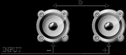
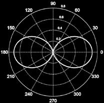
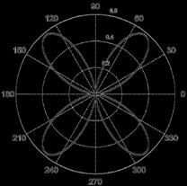
50 SUBWOOFER CLUSTERS [20/32] POLAR RESPONSE OPTIMIZATION Subwoofer clusters Let s start by configuring two omni subwoofers to give a cardioid polar response Optimized for 60 Hz Spacing = 1.43 m Electronic delay = 4.17 ms Polarity = sub 1 (normal), sub 2 (reverse)
51 SUBWOOFER CLUSTERS [21/32] POLAR RESPONSE OPTIMIZATION Subwoofer clusters Let s start by configuring two omni subwoofers to give a cardioid polar response
52 SUBWOOFER CLUSTERS [22/32] POLAR RESPONSE OPTIMIZATION Subwoofer clusters Not let s add a third subwoofer to cover the side audience area Physical spacing (from sub 1) = 1.43 m Electronic delay (from sub 1) = 4.17 ms Polarity = sub 3 (reverse)
![SUBWOOFER CLUSTERS [23/32] POLAR RESPONSE OPTIMIZATION Subwoofer](/docs-images/77/75616926/images/53-0.jpg "clusters Not let s add a third subwoofer to cover the side audience")
53 SUBWOOFER CLUSTERS [23/32] POLAR RESPONSE OPTIMIZATION Subwoofer clusters Not let s add a third subwoofer to cover the side audience area
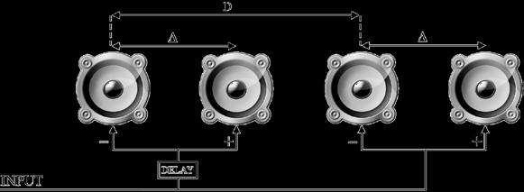
54 SUBWOOFER CLUSTERS [24/32] POLAR RESPONSE OPTIMIZATION Subwoofer clusters There isn t great rejection on stage let s fix that! Add a 4 th subwoofer Physical spacing (from sub 2/3) = 1.43 m Electronic delay (from sub 1) = 0 ms Polarity = sub 4 (reverse)
![SUBWOOFER CLUSTERS [25/32] POLAR RESPONSE OPTIMIZATION](/docs-images/77/75616926/images/55-1.jpg "Subwoofer clusters There isn t great rejection on stage, let s")
55 SUBWOOFER CLUSTERS [25/32] POLAR RESPONSE OPTIMIZATION Subwoofer clusters There isn t great rejection on stage, let s fix that!
![SUBWOOFER CLUSTERS [26/32] POLAR](/docs-images/77/75616926/images/56-0.jpg "RESPONSE OPTIMIZATION Subwoofer")

56 SUBWOOFER CLUSTERS [26/32] POLAR RESPONSE OPTIMIZATION Subwoofer clusters (gradient) How does this operate at other frequencies? 30 HZ 60 HZ 120 HZ
![SUBWOOFER CLUSTERS [27/32] POLAR](/docs-images/77/75616926/images/57-1.jpg "RESPONSE OPTIMIZATION Subwoofer")

57 SUBWOOFER CLUSTERS [27/32] POLAR RESPONSE OPTIMIZATION Subwoofer clusters (end fire) How does this operate at other frequencies? 30 HZ 60 HZ 120 HZ


58 SUBWOOFER CLUSTERS [28/32] POLAR RESPONSE OPTIMIZATION Again, let s have a look at the measurements
![SUBWOOFER CLUSTERS [29/32] GRADIENT END-FIRE # Spacing Polarity Delay Polarity Delay 1 0.85 m Normal 0.00 ms Normal 2.](/docs-images/77/75616926/images/59-0.jpg "48 ms 2 (front-tofront) Reverse 2.48 ms Normal 0.00 ms 3 Reverse 2.48 ms Normal 0.00 ms 4 100 Hz Reverse 0.00 ms Reverse 0.")
59 SUBWOOFER CLUSTERS [29/32] GRADIENT END-FIRE # Spacing Polarity Delay Polarity Delay m Normal 0.00 ms Normal 2.48 ms 2 (front-tofront) Reverse 2.48 ms Normal 0.00 ms 3 Reverse 2.48 ms Normal 0.00 ms Hz Reverse 0.00 ms Reverse 0.00 ms


60 SUBWOOFER CLUSTERS [30/32] 40 HZ 63 HZ 80 HZ 100 HZ Gradient configuration End-fire configuration
61 SUBWOOFER CLUSTERS [31/32] POLAR RESPONSE OPTIMIZATION Cardioid subwoofer clusters Cardioid subwoofers (or stacks) give more precise polar response control Similar to Dave Rat s approach
![SUBWOOFER CLUSTERS [32/32]](/docs-images/77/75616926/images/62-0.jpg "POLAR RESPONSE OPTIMIZATION")


62 SUBWOOFER CLUSTERS [32/32] POLAR RESPONSE OPTIMIZATION Cardioid subwoofer clusters Delay: D 1 = 0 D 2 = 0.5d D 3 = 2d D 4 = 0 Delay: D 1 = 0 D 2 = d D 3 = 0 D 4 = d Delay: D 1 = 0 D 2 = 0 D 3 = 1.5d D 4 = 0.5d Delay: D 1 = 0 D 2 = 2d D 3 = 2d D 4 = d d = propagation delay between units (ms)
63 GOALS + CHALLENGES SINGLE SUBWOOFERS SUBWOOFER CLUSTERS HORIZONTAL ARRAYS VERTICAL ARRAYS SIGNAL PROCESSING TECHNIQUES PERCEPTUAL CONSIDERATIONS RECOMMENDATIONS
64 HORIZONTAL ARRAYS [01/35] SUBWOOFER SPACING Typical left + right configuration, 20 m spacing
65 HORIZONTAL ARRAYS [02/35] SUBWOOFER SPACING Typical left + right configuration, 12 m spacing
66 HORIZONTAL ARRAYS [03/35] SUBWOOFER SPACING Typical left + right configuration, 8 m spacing
67 HORIZONTAL ARRAYS [04/35] SUBWOOFER SPACING Typical left + right configuration, 4 m spacing
68 HORIZONTAL ARRAYS [05/35] SUBWOOFER SPACING Typical left + right configuration, 2 m spacing
69 HORIZONTAL ARRAYS [06/35] SUBWOOFER SPACING Typical left + right configuration, 1 m spacing
70 HORIZONTAL ARRAYS [07/35] SUBWOOFER SPACING Single central subwoofer
![HORIZONTAL ARRAYS [08/35]](/docs-images/77/75616926/images/71-0.jpg "SUBWOOFER SPACING Spatial")

71 HORIZONTAL ARRAYS [08/35] SUBWOOFER SPACING Spatial variance dropped once subwoofers were within 2 m of one another why?
72 HORIZONTAL ARRAYS [09/35] SUBWOOFER SPACING Spatial variance dropped once subwoofers were within 2 m of one another why? Upper analysis frequency = 100 Hz 100 Hz = 3.42 m ½ 100 Hz = 1.72 m Sources must be within ½ a wavelength of each other in order to properly couple (line array theory)
73 HORIZONTAL ARRAYS [10/35] SUBWOOFER SPACING Most events need more than 2 stacks of subwoofers 4 subwoofer stacks with 2 m spacing
74 HORIZONTAL ARRAYS [11/35] SUBWOOFER SPACING Most events need more than 2 stacks of subwoofers 8 subwoofer stacks with 2 m spacing
75 HORIZONTAL ARRAYS [12/35] SUBWOOFER SPACING Most events need more than 2 stacks of subwoofers 16 subwoofer stacks with 2 m spacing
76 HORIZONTAL ARRAYS [13/35] SUBWOOFER SPACING Subwoofer spacing vs. SV, MOL and MOL (w/lff)
77 HORIZONTAL ARRAYS [14/35] COVERAGE CONTROL Processors allow for electronic delay on each channel Can this be used to alter the coverage pattern?
78 HORIZONTAL ARRAYS [15/35] COVERAGE CONTROL PERFECT DELAY Delay all subwoofers to the edge of the audience Result = wider coverage? Example: 8 stacks, spaced for coupling up to 60 Hz Calibration point distance = 25 m
79 HORIZONTAL ARRAYS [16/35] COVERAGE CONTROL PERFECT DELAY POST-ADJUSTMENT PRE-ADJUSTMENT Didn t exactly improve the situation why not?
80 HORIZONTAL ARRAYS [17/35] COVERAGE CONTROL PERFECT DELAY Perfectly delaying the system to the edge of the audience only optimizes the response at that point If the audience is wide, this won t work! Instead, we need to find a good compromise an imperfect delay approach
81 HORIZONTAL ARRAYS [18/35] COVERAGE CONTROL IMPERFECT DELAY My approach 1. Calculate propagation delay from each source to calibration point 2. Determine time difference of arrival (TDOA) for each source 3. Apply TDOAs to opposite pairs in array (i.e. 1 to 4, 2 to 3, 3 to 2, 4 to 1 for half of an 8 sub array)
![HORIZONTAL ARRAYS [19/35] COVERAGE](/docs-images/77/75616926/images/82-0.jpg "CONTROL IMPERFECT DELAY IMPERFECT")

82 HORIZONTAL ARRAYS [19/35] COVERAGE CONTROL IMPERFECT DELAY IMPERFECT DELAY PERFECT DELAY Much better, but still isn t perfect from Hz
![HORIZONTAL ARRAYS [20/35] COVERAGE CONTROL This](/docs-images/77/75616926/images/83-0.jpg "is the exact problem I encountered this past")
83 HORIZONTAL ARRAYS [20/35] COVERAGE CONTROL This is the exact problem I encountered this past summer
84 HORIZONTAL ARRAYS [21/35] COVERAGE CONTROL SPACING COMPENSATION We re still having issues above 70 Hz or so This is likely due a slight increase in the effective unit-to-unit spacing due to the electronic delay on top of too wide spacing for > 60 Hz Lack of coupling in the upper frequency range What if we adjusted the physical spacing of the subwoofers, to maintain consistency and coupling?
85 HORIZONTAL ARRAYS [22/35] COVERAGE CONTROL SPACING COMPENSATION W/COMPENSATION W/O COMPENSATION Not too bad!
86 HORIZONTAL ARRAYS [23/35] COVERAGE CONTROL AMPLITUDE SHADING We re in pretty good shape now If you want to further optimize your array, you can apply amplitude shading I won t go into the specifics now, but we can examine a simple example Amplitude attenuated linearly from 0 db to -6 db across the array (from the center to outside) Much better approaches available, but that s a talk for a another day!
![HORIZONTAL ARRAYS [24/35] COVERAGE CONTROL AMPLITUDE SHADING W/AMP](/docs-images/77/75616926/images/87-0.jpg "SHADING W/O AMP SHADING Slight improvement in SV, but note the -2.")
87 HORIZONTAL ARRAYS [24/35] COVERAGE CONTROL AMPLITUDE SHADING W/AMP SHADING W/O AMP SHADING Slight improvement in SV, but note the -2.5 db MOL
88 HORIZONTAL ARRAYS [25/35] COVERAGE CONTROL COVERAGE WIDTH Our coverage is on the narrow side This can be easily addressed by switching your calibration point Closer = wider coverage Further = narrower coverage
89 HORIZONTAL ARRAYS [26/35] COVERAGE CONTROL COVERAGE WIDTH Widened coverage, as desired. Slight increase in SV
![HORIZONTAL ARRAYS [27/35] COVERAGE CONTROL HOW DID WE DO?](/docs-images/77/75616926/images/90-0.jpg "POST-OPTIMIZATION PRE-OPTIMIZATION Consistent tonality, natural SPL")
90 HORIZONTAL ARRAYS [27/35] COVERAGE CONTROL HOW DID WE DO? POST-OPTIMIZATION PRE-OPTIMIZATION Consistent tonality, natural SPL loss with distance
91 HORIZONTAL ARRAYS [28/35] STAGE EFFECTS The stage can destroy the polar response of subwoofers! The reflection(s) from under the stage prevent the desired pattern to form
92 HORIZONTAL ARRAYS [29/35] STAGE EFFECTS Key consideration: When using cardioid subwoofers/clusters the stage can significantly affect the polar response Things to remember: Placing directional subwoofer systems under or on a stage can destroy directionality Simple solution: Place subwoofers in front of the stage. Avoid acoustically non-transparent stage skirts
![HORIZONTAL ARRAYS [30/35] STAGE EFFECTS Subwoofer placement Free-field Under stage On top of](/docs-images/77/75616926/images/93-0.jpg "stage In front of stage Front-to-rear rejection (db) 11.76 db 3.91 db* 8.48 db 12.")

93 HORIZONTAL ARRAYS [30/35] STAGE EFFECTS Subwoofer placement Free-field Under stage On top of stage In front of stage Front-to-rear rejection (db) db 3.91 db* 8.48 db db * modelled data due to stage height restrictions Hill, A.J.; J. Paul. The effect of performance stages on subwoofer polar and frequency responses. Proc. IOA Reproduced Sound, Southampton, UK. November 2016.
![HORIZONTAL ARRAYS [31/35] STAGE EFFECTS Most simulation software ignores the stage](/docs-images/77/75616926/images/94-0.jpg "Many engineers place subwoofers under the stage How does this affect polar response?")
94 HORIZONTAL ARRAYS [31/35] STAGE EFFECTS Most simulation software ignores the stage Many engineers place subwoofers under the stage How does this affect polar response?
![HORIZONTAL ARRAYS [32/35] STAGE EFFECTS Stage is essential for](/docs-images/77/75616926/images/95-0.jpg "accurate simulations!")
95 HORIZONTAL ARRAYS [32/35] STAGE EFFECTS Stage is essential for accurate simulations! NO STAGE IN SIMULATION STAGE INCLUDED IN SIMULATION
![HORIZONTAL ARRAYS [33/35] AUDIENCE EFFECTS We ve thus far ignored any acoustic effects of the](/docs-images/77/75616926/images/96-0.jpg "audience on low-frequency coverage Does the audience affect ground-based subwoofer system")
96 HORIZONTAL ARRAYS [33/35] AUDIENCE EFFECTS We ve thus far ignored any acoustic effects of the audience on low-frequency coverage Does the audience affect ground-based subwoofer system performance?
97 HORIZONTAL ARRAYS [34/35] AUDIENCE EFFECTS YES! Excellent work has been done by Elena Shabalina (now at d&b audiotecknik) Summary of findings: Tightly-packed audiences causes an acoustical impedance mismatch at their boundaries Results in the audience behaving as a room (of sorts), causing room mode-like behavior!
![HORIZONTAL ARRAYS [35/35] AUDIENCE EFFECTS](/docs-images/77/75616926/images/98-0.jpg "Shabalina, E.")

98 HORIZONTAL ARRAYS [35/35] AUDIENCE EFFECTS Shabalina, E. The propagation of low frequency sound through an audience. PhD dissertation (p 38), RWTH Aachen University, 2013.
99 GOALS + CHALLENGES SINGLE SUBWOOFERS SUBWOOFER CLUSTERS HORIZONTAL ARRAYS VERTICAL ARRAYS SIGNAL PROCESSING TECHNIQUES PERCEPTUAL CONSIDERATIONS RECOMMENDATIONS
![VERTICAL ARRAYS [1/4] GROUND-BASED VS.](/docs-images/77/75616926/images/100-0.jpg "FLOWN ARRAYS Flown arrays (L + R hangs) Advantages Even front to back coverage Better sightlines Disadvantages Rigging (time")
100 VERTICAL ARRAYS [1/4] GROUND-BASED VS. FLOWN ARRAYS Flown arrays (L + R hangs) Advantages Even front to back coverage Better sightlines Disadvantages Rigging (time + equipment) Less stage rejection Uneven horizontal coverage Loss of Waterhouse effect
![VERTICAL ARRAYS [2/4] GROUND-BASED VS.](/docs-images/77/75616926/images/101-0.jpg "FLOWN ARRAYS Flown arrays (center hangs) Advantages Even front to back coverage Even horizontal coverage Better sightlines")
101 VERTICAL ARRAYS [2/4] GROUND-BASED VS. FLOWN ARRAYS Flown arrays (center hangs) Advantages Even front to back coverage Even horizontal coverage Better sightlines Disadvantages Rigging (time + equipment) Less stage rejection Video sightlines? Loss of Waterhouse effect
102 VERTICAL ARRAYS [3/4] FLOWN ARRAY STEERING Cardioid pattern can be achieved in similar manner to ground-based systems Do we want the pattern to be focused directly forward?
![VERTICAL ARRAYS [4/4] FLOWN ARRAY STEERING Flown cardioid arrays can be](/docs-images/77/75616926/images/103-1.jpg "steered to focus sound energy on the audience, w/still limited stage")
103 VERTICAL ARRAYS [4/4] FLOWN ARRAY STEERING Flown cardioid arrays can be steered to focus sound energy on the audience, w/still limited stage SPL
104 GOALS + CHALLENGES SINGLE SUBWOOFERS SUBWOOFER CLUSTERS HORIZONTAL ARRAYS VERTICAL ARRAYS SIGNAL PROCESSING TECHNIQUES PERCEPTUAL CONSIDERATIONS RECOMMENDATIONS
![SIGNAL PROCESSING TECHNIQUES [01/10] EQUALIZATION Use sparingly!](/docs-images/77/75616926/images/105-0.jpg "You can t EQ for comb-filtering Excessive EQ = poor transients")
105 SIGNAL PROCESSING TECHNIQUES [01/10] EQUALIZATION Use sparingly! You can t EQ for comb-filtering Excessive EQ = poor transients
106 SIGNAL PROCESSING TECHNIQUES [02/10] TIME-ALIGNMENT A number of options available 1. Use software to get necessary delay time Tricky to get 100% correct as propagation paths to audience differs greatly Much easier for flown subwoofer arrays
107 SIGNAL PROCESSING TECHNIQUES [03/10] TIME-ALIGNMENT A number of options available 2. Run a sine wave (set to crossover frequency) through main left/right and subwoofer system simultaneously Adjust delay to subwoofers (assuming subwoofers are in front of the main PA) Listen for peak SPL in sine wave
![SIGNAL PROCESSING TECHNIQUES [04/10] POLAR RESPONSE OPTIMIZATION Many companies use DSP algorithms within their](/docs-images/77/75616926/images/108-0.jpg "processors to achieve cardioid polar responses across the subwoofer frequency band Uses a form of all-pass filter Works")
108 SIGNAL PROCESSING TECHNIQUES [04/10] POLAR RESPONSE OPTIMIZATION Many companies use DSP algorithms within their processors to achieve cardioid polar responses across the subwoofer frequency band Uses a form of all-pass filter Works very well!
109 SIGNAL PROCESSING TECHNIQUES [05/10] HEADROOM EXTENSION - EQ Old trick Apply very high-q parametric EQ at 20 Hz (or so) and attenuate as much as possible Much more headroom for the subwoofer system!
![SIGNAL PROCESSING TECHNIQUES [06/10] HEADROOM EXTENSION VIRTUAL BASS Psychoacoustical effect Principle of the missing fundamental Can](/docs-images/77/75616926/images/110-0.jpg "be used in live sound Perceived boost in low-frequency content Less risk of driver over-excursion Decreased amplification")
110 SIGNAL PROCESSING TECHNIQUES [06/10] HEADROOM EXTENSION VIRTUAL BASS Psychoacoustical effect Principle of the missing fundamental Can be used in live sound Perceived boost in low-frequency content Less risk of driver over-excursion Decreased amplification requirements
111 SIGNAL PROCESSING TECHNIQUES [07/10] DIFFUSE SIGNAL PROCESSING (DISP) Extension of old trick used by many in the industry Aimed at source decorrelation to avoid comb-filtering
112 SIGNAL PROCESSING TECHNIQUES [08/10] DIFFUSE SIGNAL PROCESSING (DISP) Originally developed for distributed mode loudspeakers (DMLs) Applies imperceptible, low-level noise-like decay onto signal (different for each loudspeaker) Frequency-dependent decay of noise (to avoid unwanted signal coloration) Static or dynamic applications
113 SIGNAL PROCESSING TECHNIQUES [09/10] DIFFUSE SIGNAL PROCESSING (DISP) Has been shown experimentally to reduce spatial variance across an audience by up to 50% (or so) Presentation tomorrow! P18 Sound Reinforcement & Acoustics, 2pm, Room 1E11
![SIGNAL PROCESSING TECHNIQUES [10/10] DIFFUSE SIGNAL PROCESSING](/docs-images/77/75616926/images/114-0.jpg "(DISP) Advantages: Moderate spatial variance reduction No")

114 SIGNAL PROCESSING TECHNIQUES [10/10] DIFFUSE SIGNAL PROCESSING (DISP) Advantages: Moderate spatial variance reduction No calibration necessary Avoids perceptible signal coloration Disadvantages: Correct implementation of phase noise essential Overuse = perceptually noticeable
115 GOALS + CHALLENGES SINGLE SUBWOOFERS SUBWOOFER CLUSTERS HORIZONTAL ARRAYS VERTICAL ARRAYS SIGNAL PROCESSING TECHNIQUES PERCEPTUAL CONSIDERATIONS RECOMMENDATIONS
116 PERCEPTUAL CONSIDERATIONS [1/5] HOW TO DRIVE THE SUBWOOFERS 1. Via the stereo bus (main left + right outputs) Advantages No extra work, easy to set up Certain level of signal decorrelation Disadvantages No control over what s fed to subwoofers Potential subwoofer overload Potential muddy signal
117 PERCEPTUAL CONSIDERATIONS [2/5] HOW TO DRIVE THE SUBWOOFERS 2. Via a mono auxiliary send Advantages Full control over what goes to the subwoofers Still fairly simple set up Disadvantages No signal decorrelation Loss of stereo image?
118 PERCEPTUAL CONSIDERATIONS [3/5] HOW TO DRIVE THE SUBWOOFERS 3. Via a stereo auxiliary send Advantages Full control over what goes to the subwoofers Moderate signal decorrelation Disadvantages (Slightly) more involved set up
119 PERCEPTUAL CONSIDERATIONS [4/5] HOW TO DRIVE THE SUBWOOFERS So what s the best option? Previous research conducted at University of Derby: Research indicates that perceptually, there is little difference between mono and stereo subwoofer systems So does it matter for large-scale live sound?
120 PERCEPTUAL CONSIDERATIONS [5/5] HOW TO DRIVE THE SUBWOOFERS Actually, yes... The experiments demonstrated reduction in LF nulls in the audience using stereo reproduction Decorrelated left + right signals cause less destructive interference A seemingly obvious conclusion that appears to have been overlooked by many in the industry
121 GOALS + CHALLENGES SINGLE SUBWOOFERS SUBWOOFER CLUSTERS HORIZONTAL ARRAYS VERTICAL ARRAYS SIGNAL PROCESSING TECHNIQUES PERCEPTUAL CONSIDERATIONS RECOMMENDATIONS
122 RECOMMENDATIONS 1. SUBWOOFER SPACING No more than ½ wavelength Keep array as wide as possible for best coverage 2. POLAR REPONSE OPTIMIZATION 3. GROUND-BASED VS. FLOWN ARRAYS 4. SIGNAL PROCESSING 5. PERCEPTUAL CONSIDERATIONS
123 RECOMMENDATIONS 1. SUBWOOFER SPACING 2. POLAR REPONSE OPTIMIZATION Cardioid pattern w/2 omni subwoofers More precise control = subwoofer clusters Be careful of polar response vs. frequency! Delay, positioning compensation and/or amplitude shading can be used to optimize coverage 3. GROUND-BASED VS. FLOWN ARRAYS 4. SIGNAL PROCESSING 5. PERCEPTUAL CONSIDERATIONS
124 RECOMMENDATIONS 1. SUBWOOFER SPACING 2. POLAR REPONSE OPTIMIZATION 3. GROUND-BASED VS. FLOWN ARRAYS Flown arrays = better front-to-back consistency Flown arrays = loss of Waterhouse effect Both varieties exhibit same spacing issues Sightlines + rigging capabilities must be considered 4. SIGNAL PROCESSING 5. PERCEPTUAL CONSIDERATIONS
125 RECOMMENDATIONS 1. SUBWOOFER SPACING 2. POLAR REPONSE OPTIMIZATION 3. GROUND-BASED VS. FLOWN ARRAYS 4. SIGNAL PROCESSING Don t over EQ! Consistent polar response w/all-pass filter Always be sure to time-align system Various DSP algorithms available to help with headroom and coverage consistency 5. PERCEPTUAL CONSIDERATIONS


126 RECOMMENDATIONS 1. SUBWOOFER SPACING 2. POLAR REPONSE OPTIMIZATION 3. GROUND-BASED VS. FLOWN ARRAYS 4. SIGNAL PROCESSING 5. PERCEPTUAL CONSIDERATIONS Stereo subs might not be essential, perceptually Stereo subs help with consistent audience coverage Sharp transients are essential!

127 THANKS FOR LISTENING! ANY QUESTIONS? The simulation software used in this tutorial is free to download at:
THE EFFECT OF PERFORMANCE STAGES ON SUBWOOFER POLAR AND FREQUENCY RESPONSES
 THE EFFECT OF PERFORMANCE STAGES ON SUBWOOFER POLAR AND FREQUENCY RESPONSES AJ Hill Department of Electronics, Computing & Mathematics, University of Derby, UK J Paul Department of Electronics, Computing
POSITIONING SUBWOOFERS
 POSITIONING SUBWOOFERS PRINCIPLE CONSIDERATIONS Lynx Pro Audio / Technical documents When you arrive to a venue and see the Front of House you can find different ways how subwoofers are placed. Sometimes
VTX V25-II Preset Guide
 VTX V25-II Preset Guide General Information: VTX V25-II Preset Guide Version: 1.1 Distribution Date: 10 / 11 / 2016 Copyright 2016 by Harman International; all rights reserved. JBL Professional 8500 Balboa
BACHELOR THESIS. Placing of Subwoofers. Measurements of common setups with 2-4 subwoofers for an even sound
 BACHELOR THESIS Placing of Subwoofers Measurements of common setups with 2-4 subwoofers for an even sound pressure lever over the audience area and lower level on the stage Linnéa Burman 2013 Bachelor
White Paper JBL s LSR Principle, RMC (Room Mode Correction) and the Monitoring Environment by John Eargle. Introduction and Background:
 and the Monitoring Environment by John Eargle. Introduction and Background:") White Paper JBL s LSR Principle, RMC (Room Mode Correction) and the Monitoring Environment by John Eargle Introduction and Background: Although a loudspeaker may measure flat on-axis under anechoic conditions,
White Paper JBL s LSR Principle, RMC (Room Mode Correction) and the Monitoring Environment by John Eargle Introduction and Background: Although a loudspeaker may measure flat on-axis under anechoic conditions,
How to Obtain a Good Stereo Sound Stage in Cars
 Page 1 How to Obtain a Good Stereo Sound Stage in Cars Author: Lars-Johan Brännmark, Chief Scientist, Dirac Research First Published: November 2017 Latest Update: November 2017 Designing a sound system
MAW218D7. User s manual. Pol.Ind.Norte-Perpinyà, TERRASSA (Barcelona-SPAIN)
") MAW218D7 User s manual Pol.Ind.Norte-Perpinyà,25 08226 TERRASSA (Barcelona-SPAIN) info@master-audio.com www.master-audio.com Nov 2008 CAUTION RISK OF ELECTRIC SHOCK DON T OPEN WARNING: To reduce the risk
MAW218D7 User s manual Pol.Ind.Norte-Perpinyà,25 08226 TERRASSA (Barcelona-SPAIN) info@master-audio.com www.master-audio.com Nov 2008 CAUTION RISK OF ELECTRIC SHOCK DON T OPEN WARNING: To reduce the risk
DESIGNING OPTIMIZED MICROPHONE BEAMFORMERS
 3235 Kifer Rd. Suite 100 Santa Clara, CA 95051 www.dspconcepts.com DESIGNING OPTIMIZED MICROPHONE BEAMFORMERS Our previous paper, Fundamentals of Voice UI, explained the algorithms and processes required
TOUR SERIES LOUDSPEAKER SYSTEMS
 TOUR SERIES LOUDSPEAKER SYSTEMS From Fender Pro Audio Owner's Manual for 2912(c), 2915(c) P/N 050757 Fender Musical Instruments 7975 North Hayden Road, Scottsdale, Arizona 85258 U.S.A. Fender knows the
DRM212 DRM215 DRM315 SPECIFICATIONS
 DRM212 DRM215 DRM315 DRM Series Professional Powered Loudspeakers deliver class-leading power via ultra-efficient Class-D amplifiers with next-gen protection and Power Factor Correction technology for
Application note for Peerless XLS 12" subwoofer driver
 Application note for Peerless XLS 12" subwoofer driver Introduction: The following is an application note of how to use the Peerless XLS 12" driver especially designed for subwoofers. The application note
Xsub v5.0 cardioid and supercardioid ground-stack array settings
 Cardioid subwoofer array settings Cardioid subwoofer arrays can be used to direct the output of an array of subwoofers in order to limit excessive amounts of bass in undesired locations. Cardioid arrays
MAD A-Series...Flat Panel Surface Planar Arrays
 HPV TECHNOLOGIES, Inc. 17752 Fitch Irvine, California 92614 MAD A-Series...Flat Panel Surface Planar Arrays...Concert Sound at it s Finest! Flat Panel Surface Planar Arrays describe a new speaker technology
The Cocktail Party Effect. Binaural Masking. The Precedence Effect. Music 175: Time and Space
 The Cocktail Party Effect Music 175: Time and Space Tamara Smyth, trsmyth@ucsd.edu Department of Music, University of California, San Diego (UCSD) April 20, 2017 Cocktail Party Effect: ability to follow
Put your sound where it belongs: Numerical optimization of sound systems. Stefan Feistel, Bruce C. Olson, Ana M. Jaramillo AFMG Technologies GmbH
 Put your sound where it belongs: Stefan Feistel, Bruce C. Olson, Ana M. Jaramillo Technologies GmbH 166th ASA, San Francisco, 2013 Sound System Design Typical Goals: Complete Coverage High Level and Signal/Noise-Ratio
White Paper Measuring and Optimizing Sound Systems: An introduction to JBL Smaart
 White Paper Measuring and Optimizing Sound Systems: An introduction to JBL Smaart by Sam Berkow & Alexander Yuill-Thornton II JBL Smaart is a general purpose acoustic measurement and sound system optimization
dbtechnologies QUICK REFERENCE
 dbtechnologies QUICK REFERENCE 1 DVA Composer Ver3.1 dbtechnologies What s new in version 3.1 COMPOSER WINDOW - DVA T8 line array module now available in the System Models window. - Adding modules in the
Figure 1. JBL VLA901H System
 White Paper v.2 JBL Variable Line Array Technology Achieving Optimum Line Array Performance Through High Performance Horn-Loaded Modular Design by Brad Ricks Introduction Line arrays have become an attractive
Con o t n e t n e t n s t
 Contents Page Item 3 Safety Warnings 4 Glossary 5 Attachment and Removal of Caster Frames 6 Line Array Element Attachment 7 Angle Selection 8 Rigging Frame (Bumper) 9 Electrical connection 10 System Mounting
front: 6.25"(159mm) W x 9.25"(235mm) H rear: 5.625"(143mm) W x 9.25"(235mm) H depth: 7"(178mm)
 W x 9.25(235mm) H rear: 5.625(143mm) W x 9.25(235mm) H depth: 7(178mm)") Introducing the Apogee Fixed Installation Series... AFI Loudspeakers The Apogee AFI Series provides what sound contractors demand - high quality, highly reliable loudspeakers at a competitive price. Models
Introducing the Apogee Fixed Installation Series... AFI Loudspeakers The Apogee AFI Series provides what sound contractors demand - high quality, highly reliable loudspeakers at a competitive price. Models
THE DIGITAL DELAY ADVANTAGE A guide to using Digital Delays. Synchronize loudspeakers Eliminate comb filter distortion Align acoustic image.
 THE DIGITAL DELAY ADVANTAGE A guide to using Digital Delays Synchronize loudspeakers Eliminate comb filter distortion Align acoustic image Contents THE DIGITAL DELAY ADVANTAGE...1 - Why Digital Delays?...
TI 385 d&b Line array design 10.1 en
 385 TI 385 d&b Line array design 10.1 en General information TI 385 d&b Line array design Version: 10.1 en, 06/2018, D5385.EN.10 Copyright 2018 by d&b audiotechnik GmbH; all rights reserved. d&b audiotechnik
LIVERPOOL TLX43. Custom-Engineered Drivers
 Compact 2 way line array element for portable and fixed installation application 15 Watts continuous, 6 Watts peak power Ideal for FOH, center cluster, offstage fill, stereo in-fill or distributed fill
inter.noise 2000 The 29th International Congress and Exhibition on Noise Control Engineering August 2000, Nice, FRANCE
 Copyright SFA - InterNoise 2000 1 inter.noise 2000 The 29th International Congress and Exhibition on Noise Control Engineering 27-30 August 2000, Nice, FRANCE I-INCE Classification: 6.1 INFLUENCE OF THE
CPH-10 SUBWOOFER OWNERS MANUAL
 CPH-10 SUBWOOFER OWNERS MANUAL www.artcoustic.com Welcome to the world of Artcoustic! Congratulations with your purchase of the Artcoustic CPH-10 Subwoofer. The CPH-10 has an efficient design, producing
XXXXXX - A new approach to Loudspeakers & room digital correction
 XXXXXX - A new approach to Loudspeakers & room digital correction Background The idea behind XXXXXX came from unsatisfying results from traditional loudspeaker/room equalization methods to get decent sound
DIGITAL SPEAKER MANAGEMENT UK
 DSM2-6mkII DIGITAL SPEAKER MANAGEMENT 170.659UK Features 96kHz sampling frequency, 32-bit A/D and D/A converter, 24-bit DSP processor Input channel: 6-band parametric EQ, Delay, Polarity Output channel:
Anti-Mode 8033Cinema User's Manual
 Anti-Mode 8033Cinema User's Manual Revision History Rev. Date Author Affected chapters Description 1.0 2007-11-30 TK & ToLi All Original version Finnish and English for 8033B 1.8 2012-02-15 POj All Updated
How Close Can They be Stacked? By K0CQ. How close can yagis for harmonically related bands be stacked? What are the consequences of close stacking?
 How Close Can They be Stacked? By K0CQ How close can yagis for harmonically related bands be stacked? What are the consequences of close stacking? This study has been inspired by Kent Britain's display
Multi-Purpose Auditorium Sound Reinforcement System Design ECE Spring 2017
 Multi-Purpose Auditorium Sound Reinforcement System Design ECE 40020 Spring 2017 Left to right: Maxwell Risinger, Riley Shannon, Skyler Carrico, Guanghua Zha Outline Primary System Design Constraints Venue
RoomMatch RM and RM TECHNICAL DATA SHEET. asymmetrical array modules. Key Features. Product Overview. Technical Specifications
 RoomMatch RM281 and RM281 Key Features All the benefits of the original 2 RoomMatch array module loudspeakers - Concert-quality sound quality for live music and outstanding spoken-word clarity with industry-leading
DTS Neural Mono2Stereo
 WAVES DTS Neural Mono2Stereo USER GUIDE Table of Contents Chapter 1 Introduction... 3 1.1 Welcome... 3 1.2 Product Overview... 3 1.3 Sample Rate Support... 4 Chapter 2 Interface and Controls... 5 2.1 Interface...
Technical Guide. Installed Sound. Loudspeaker Solutions for Worship Spaces. TA-4 Version 1.2 April, Why loudspeakers at all?
 Installed Technical Guide Loudspeaker Solutions for Worship Spaces TA-4 Version 1.2 April, 2002 systems for worship spaces can be a delight for all listeners or the horror of the millennium. The loudspeaker
USER MANUAL FOR DDT 2D. Introduction. Installation. Getting Started. Danley Design Tool 2d. Welcome to the Danley Design Tool 2D program.
 USER MANUAL FOR DDT 2D ( VERSION 1.8) Welcome to the Danley Design Tool 2D program. Introduction DDT2D is a very powerful tool that lets the user visualize how sound propagates from loudspeakers, including
RECORDING AND REPRODUCING CONCERT HALL ACOUSTICS FOR SUBJECTIVE EVALUATION
 RECORDING AND REPRODUCING CONCERT HALL ACOUSTICS FOR SUBJECTIVE EVALUATION Reference PACS: 43.55.Mc, 43.55.Gx, 43.38.Md Lokki, Tapio Aalto University School of Science, Dept. of Media Technology P.O.Box
PSYCHOACOUSTICS & THE GRAMMAR OF AUDIO (By Steve Donofrio NATF)
") PSYCHOACOUSTICS & THE GRAMMAR OF AUDIO (By Steve Donofrio NATF) "The reason I got into playing and producing music was its power to travel great distances and have an emotional impact on people" Quincey
PSYCHOACOUSTICS & THE GRAMMAR OF AUDIO (By Steve Donofrio NATF) "The reason I got into playing and producing music was its power to travel great distances and have an emotional impact on people" Quincey
Difficult acoustic environments? Maintaining voice intelligibility
 Difficult acoustic environments? Maintaining voice intelligibility Measurement Conventions Speech transmission index, Alcons and all the others Measurement Conventions % Alcons, STI or C50? %ALcons = Articulation
UB22z Specifications. 2-WAY COMPACT FULL-RANGE See NOTES TABULAR DATA for details CONFIGURATION Subsystem DESCRIPTION
 DESCRIPTION Ultra-compact 2-way system Wide projection pattern LF on angled baffles to maintain a wide upper/midrange beamwidth High output, high definition sound DESCRIPTION The UB22z is engineered for
Brochure ELODIS-SUB-VB21. Copyright by Franz Hinterlehner 1. Version L for deeper bass reproduction Version H for higher sound pressure level
 Copyright by Franz Hinterlehner 1 Brochure ELODIS-SUB-VB21 Version L for deeper bass reproduction Version H for higher sound pressure level 1 Copyright by Franz Hinterlehner 2 2 Copyright by Franz Hinterlehner
BeoVision Televisions
 BeoVision Televisions Technical Sound Guide Bang & Olufsen A/S January 4, 2017 Please note that not all BeoVision models are equipped with all features and functions mentioned in this guide. Contents 1
TI 385 (4.0 EN) d&b Line array design, ArrayCalc V7.x
 d&b Line array design, ArrayCalc V7.x") TI 385 (4.0 EN) d&b Line array design, ArrayCalc V7.x Contents 1. Introduction...3 2. The J-Series line array...3 2.1 Number of cabinets required...3 2.2 J-SUB subwoofer setup...3 2.2.1 J-SUB ground stacks...4
TI 385 (4.0 EN) d&b Line array design, ArrayCalc V7.x Contents 1. Introduction...3 2. The J-Series line array...3 2.1 Number of cabinets required...3 2.2 J-SUB subwoofer setup...3 2.2.1 J-SUB ground stacks...4
AcoustiSoft RPlusD ver
 AcoustiSoft RPlusD ver 1.2.03 Feb 20 2007 Doug Plumb doug@etfacoustic.com http://www.etfacoustic.com/rplusdsite/index.html Software Overview RPlusD is designed to provide all necessary function to both
MULTISIM DEMO 9.5: 60 HZ ACTIVE NOTCH FILTER
 9.5(1) MULTISIM DEMO 9.5: 60 HZ ACTIVE NOTCH FILTER A big problem sometimes encountered in audio equipment is the annoying 60 Hz buzz which is picked up because of our AC power grid. Improperly grounded
Proceedings of Meetings on Acoustics
 Proceedings of Meetings on Acoustics Volume 19, 2013 http://acousticalsociety.org/ ICA 2013 Montreal Montreal, Canada 2-7 June 2013 Architectural Acoustics Session 3aAAb: Architectural Acoustics Potpourri
S-Series Configurations
 S-Series Configurations Adamson s S-Series underwent extensive research and field testing with key rental and installation partners before its availability to the public. Through these partnerships we
M44 Multisonic Imager M86 Multisonic Imager. Operation Manual. Miles Technology Inc. Niles, Michigan USA
 M44 Multisonic Imager M86 Multisonic Imager Operation Manual Miles Technology Inc. Niles, Michigan USA Miles Technology Inc. Niles, Michigan USA M44 and M86 Multisonic Imager Operation Manual ABOUT THE
A Straightforward One-Seat Stereo Tuning Process and Some Notes About Why it Works
 A Straightforward One-Seat Stereo Tuning Process and Some Notes About Why it Works The Process Note 1: This process assumes the input to your DSP is confirmed as a flat, two-channel and in phase signal,
A Real Word Case Study E- Trap by Bag End Ovasen Studios, New York City
 21 March 2007 070315 - dk v5 - Ovasen Case Study Written by David Kotch Edited by John Storyk A Real Word Case Study E- Trap by Bag End Ovasen Studios, New York City 1. Overview - Description of Problem
A Real Word Case Study E- Trap by Bag End Ovasen Studios, New York City
 21 March 2007 070315 - dk v5 - Ovasen Case Study Written by David Kotch Edited by John Storyk A Real Word Case Study E- Trap by Bag End Ovasen Studios, New York City 1. Overview - Description of Problem
The simplest way to stop a mic from ringing feedback. Not real practical if the intent is to hear more of the choir in our PA.
 Lose the Feeback Improving Gain-Before-Feedback in Worship Sennheiser HOW Applications Tip #9 Kent Margraves, June 2008 *This discussion focuses on the processing and optimization of miked sources on the
Understanding PQR, DMOS, and PSNR Measurements
 Understanding PQR, DMOS, and PSNR Measurements Introduction Compression systems and other video processing devices impact picture quality in various ways. Consumers quality expectations continue to rise
Proceedings of Meetings on Acoustics
 Proceedings of Meetings on Acoustics Volume 19, 2013 http://acousticalsociety.org/ ICA 2013 Montreal Montreal, Canada 2-7 June 2013 Psychological and Physiological Acoustics Session 4aPPb: Binaural Hearing
Award Winning Stereo-to-5.1 Surround Up-mix Plugin
 Award Winning Stereo-to-5.1 Surround Up-mix Plugin Sonic Artifact-Free Up-Mix Improved Digital Signal Processing 100% ITU Fold-back to Original Stereo 32/64-bit support for VST and AU formats More intuitive
Measurement of overtone frequencies of a toy piano and perception of its pitch
 Measurement of overtone frequencies of a toy piano and perception of its pitch PACS: 43.75.Mn ABSTRACT Akira Nishimura Department of Media and Cultural Studies, Tokyo University of Information Sciences,
DSP Monitoring Systems. dsp GLM. AutoCal TM
 DSP Monitoring Systems dsp GLM AutoCal TM Genelec DSP Systems - 8200 bi-amplified monitor loudspeakers and 7200 subwoofers For decades Genelec has measured, analyzed and calibrated its monitoring systems
ROOM LOW-FREQUENCY RESPONSE ESTIMATION USING MICROPHONE AVERAGING
 ROOM LOW-FREQUENCY RESPONSE ESTIMATION USING MICROPHONE AVERAGING Julius Newell, Newell Acoustic Engineering, Lisbon, Portugal Philip Newell, Acoustics consultant, Moaña, Spain Keith Holland, ISVR, University
A-Line LOUDSPEAKER SYSTEM. Mobile Audio Concert Sound Fixed Installation Pro Entertainment. English
 A-Line LOUDSPEAKER SYSTEM Mobile Audio Concert Sound Fixed Installation Pro Entertainment English A-LINE FAMILY A Perfect Match THE A-LINE IS YOUR ENTRY TO PROFESSIONAL DYNACORD LIVE SOUND Powered loudspeakers
CM3106 Solutions. Do not turn this page over until instructed to do so by the Senior Invigilator.
 CARDIFF UNIVERSITY EXAMINATION PAPER Academic Year: 2013/2014 Examination Period: Examination Paper Number: Examination Paper Title: Duration: Autumn CM3106 Solutions Multimedia 2 hours Do not turn this
In addition, the choice of crossover frequencies has been expanded to include the range from 40 Hz to 220 Hz in 10 Hz increments.
 Theta Digital Casablanca III HD and Casablanca IV The Casablanca platform traditionally had a number or proprietary features that made it unique. Some of them have been replaced. What s gone? What s replaced
ELECTRO-ACOUSTIC SYSTEMS FOR THE NEW OPERA HOUSE IN OSLO. Alf Berntson. Artifon AB Östra Hamngatan 52, Göteborg, Sweden
 ELECTRO-ACOUSTIC SYSTEMS FOR THE NEW OPERA HOUSE IN OSLO Alf Berntson Artifon AB Östra Hamngatan 52, 411 08 Göteborg, Sweden alf@artifon.se ABSTRACT In this paper the requirements and design of the sound
Application note for Peerless XLS 10" and XLS 12" subwoofer drivers for cars
 Application note for Peerless XLS 10" and XLS 12" subwoofer drivers for cars Introduction: The following is an application note of how to use the Peerless XLS family of subwoofer drive units especially
How Close Can They be Stacked? By K0CQ. How close can yagis for harmonically related bands be stacked? What are the consequences of close stacking?
 How Close Can They be Stacked? By K0CQ How close can yagis for harmonically related bands be stacked? What are the consequences of close stacking? This study has been inspired by Kent Britain's display
Portable Speakers. 2,500 Watt 2 Way 8" Powered Loudspeaker with KLARK TEKNIK DSP Technology, Speaker Modelling and ULTRANET Networking
 2 way full range loudspeaker for portable PA and installation applications 2,5 Watt power featuring KLARK TEKNIK Class-D technology KLARK TEKNIK Digital Signal Processing for total system control Speaker
Audio Engineering Society. Convention Paper. Presented at the 141st Convention 2016 September 29 October 2 Los Angeles, USA
 Audio Engineering Society Convention Paper Presented at the 141st Convention 2016 September 29 October 2 Los Angeles, USA This Convention paper was selected based on a submitted abstract and 750-word precis
fluidaudio.net FLUID AUDIO Buyers Guide
 fluidaudio.net FLUID AUDIO Buyers Guide CONTENTS About Fluid Audio... Page 2 Classic Series (C5 & C5W)... Page 4 Bluetooth Series (C5BT & C5BTW)... Page 6 Fader Series (F4, F5 & F8S)... Page 8 Fader Series
Mixing in the Box A detailed look at some of the myths and legends surrounding Pro Tools' mix bus.
 From the DigiZine online magazine at www.digidesign.com Tech Talk 4.1.2003 Mixing in the Box A detailed look at some of the myths and legends surrounding Pro Tools' mix bus. By Stan Cotey Introduction
E15X-SUB Manual (1.2 EN)
") E15X-SUB Manual (1.2 EN) Symbols on the equipment Please refer to the information in the operating manual. WARNING! Dangerous voltage! Contents Safety precautions...3 Information regarding use of loudspeakers...3
E15X-SUB Manual (1.2 EN) Symbols on the equipment Please refer to the information in the operating manual. WARNING! Dangerous voltage! Contents Safety precautions...3 Information regarding use of loudspeakers...3
Immersive. 6.5HD Line Arrays. Description: Features: Applications:
 Immersive HD 6.5HD Line Arrays Description: Utilizing our Model 6.5HD module as the building block for customized Immersive Array s. Systems can be designed for any fixed application or venue with up to
SoundField SurroundZone2. User Guide Version 1.0
 SoundField SurroundZone2 Version 1.0 CONTENTS: Introduction 2 Explanation of Controls: Input Section 3 Explanation of Controls: Output Section 4 Surround Controls 6 1 P a g e INTRODUCTION The SurroundZone2
BER MEASUREMENT IN THE NOISY CHANNEL
 BER MEASUREMENT IN THE NOISY CHANNEL PREPARATION... 2 overview... 2 the basic system... 3 a more detailed description... 4 theoretical predictions... 5 EXPERIMENT... 6 the ERROR COUNTING UTILITIES module...
Hugo Technology. An introduction into Rob Watts' technology
 Hugo Technology An introduction into Rob Watts' technology Copyright Rob Watts 2014 About Rob Watts Audio chip designer both analogue and digital Consultant to silicon chip manufacturers Designer of Chord
DP1 DYNAMIC PROCESSOR MODULE OPERATING INSTRUCTIONS
 DP1 DYNAMIC PROCESSOR MODULE OPERATING INSTRUCTIONS and trouble-shooting guide LECTROSONICS, INC. Rio Rancho, NM INTRODUCTION The DP1 Dynamic Processor Module provides complete dynamic control of signals
AMEK SYSTEM 9098 DUAL MIC AMPLIFIER (DMA) by RUPERT NEVE the Designer
 by RUPERT NEVE the Designer") AMEK SYSTEM 9098 DUAL MIC AMPLIFIER (DMA) by RUPERT NEVE the Designer If you are thinking about buying a high-quality two-channel microphone amplifier, the Amek System 9098 Dual Mic Amplifier (based on
AMEK SYSTEM 9098 DUAL MIC AMPLIFIER (DMA) by RUPERT NEVE the Designer If you are thinking about buying a high-quality two-channel microphone amplifier, the Amek System 9098 Dual Mic Amplifier (based on
D. BARD, J. NEGREIRA DIVISION OF ENGINEERING ACOUSTICS, LUND UNIVERSITY
 Room Acoustics (1) D. BARD, J. NEGREIRA DIVISION OF ENGINEERING ACOUSTICS, LUND UNIVERSITY Outline Room acoustics? Parameters Summary D. Bard, J. Negreira / May 2018 Basics All our life happens (mostly)
LS4 & LS3 Specifications. Available Finishes
 Our namesake Wisdom Series introduces our latest planar magnetic thin-film technology and represents an uncompromised engineering effort to achieve the ultimate in music and film sound reproduction. The
Draft 100G SR4 TxVEC - TDP Update. John Petrilla: Avago Technologies February 2014
 Draft 100G SR4 TxVEC - TDP Update John Petrilla: Avago Technologies February 2014 Supporters David Cunningham Jonathan King Patrick Decker Avago Technologies Finisar Oracle MMF ad hoc February 2014 Avago
MIE 402: WORKSHOP ON DATA ACQUISITION AND SIGNAL PROCESSING Spring 2003
 MIE 402: WORKSHOP ON DATA ACQUISITION AND SIGNAL PROCESSING Spring 2003 OBJECTIVE To become familiar with state-of-the-art digital data acquisition hardware and software. To explore common data acquisition
Roland V-Mixer in a Cross Matrix LCR System
 Roland V-Mixer in a Cross Matrix LCR System WHY: Many large Concert Halls and Churches are Fan Shaped, very wide. Sound coverage can be difficult. Mono is a common solution. Cross Matrix LCR is a solution
Faithful Sound Uniform Loudness Distribution Reproduction. Source. System
 Faithful Sound Uniform Loudness Distribution Reproduction Lucid ULD III Loudspeakers Althar Audio strives to protect the integrity of sounds. We recognise the delicacy of sound, beginning with its creation
Acoustic Measurements Using Common Computer Accessories: Do Try This at Home. Dale H. Litwhiler, Terrance D. Lovell
 Abstract Acoustic Measurements Using Common Computer Accessories: Do Try This at Home Dale H. Litwhiler, Terrance D. Lovell Penn State Berks-LehighValley College This paper presents some simple techniques
New recording techniques for solo double bass
 New recording techniques for solo double bass Cato Langnes NOTAM, Sandakerveien 24 D, Bygg F3, 0473 Oslo catola@notam02.no, www.notam02.no Abstract This paper summarizes techniques utilized in the process
Panaray 802 Series III TECHNICAL DATA SHEET. loudspeaker. Key Features. Product Overview. Technical Specifications
 Panaray 82 Series III Key Features Articulated Array design provides 12 x 1 coverage to deliver wide-range reproduction over a broad dispersion area Eight Bose 4.5" (114 mm) full-range drivers for unsurpassed
VCE VET MUSIC INDUSTRY: SOUND PRODUCTION
 Victorian Certificate of Education 2017 SUPERVISOR TO ATTACH PROCESSING LABEL HERE Letter STUDENT NUMBER VCE VET MUSIC INDUSTRY: SOUND PRODUCTION Aural and written examination Friday 17 November 2017 Reading
soothe audio processor Manual and FAQ
 soothe audio processor Manual and FAQ Thank you for using soothe! soothe is a spectral processor for suppressing resonances in the mid and high frequencies. It works by automatically detecting the resonances
LUCAS NANO 600 Series
 LUCAS NANO 600 Series PROFESSIONAL SOUND TO GO > LUCAS NANO 602/600/608i 1 LUCAS NANO 600 Series PROFESSIONAL SOUND TO GO > The LUCAS NANO 600 series packs professional audio performance into the most
A few white papers on various. Digital Signal Processing algorithms. used in the DAC501 / DAC502 units
 A few white papers on various Digital Signal Processing algorithms used in the DAC501 / DAC502 units Contents: 1) Parametric Equalizer, page 2 2) Room Equalizer, page 5 3) Crosstalk Cancellation (XTC),
A SIMPLE ACOUSTIC ROOM MODEL FOR VIRTUAL PRODUCTION AUDIO. R. Walker. British Broadcasting Corporation, United Kingdom. ABSTRACT
 A SIMPLE ACOUSTIC ROOM MODEL FOR VIRTUAL PRODUCTION AUDIO. R. Walker British Broadcasting Corporation, United Kingdom. ABSTRACT The use of television virtual production is becoming commonplace. This paper
18 (300mm) ultra-high excursion cone transducer, 4" (100mm) voice coil, ferrite magnet
 ultra-high excursion cone transducer, 4 (100mm) voice coil, ferrite magnet") 2400 Watt 18" Active Subwoofer with Wireless Connectivity Designed and tuned in the USA, Black Series powered subwoofers offer more power, more agility, and more intelligence than any other speaker in
2400 Watt 18" Active Subwoofer with Wireless Connectivity Designed and tuned in the USA, Black Series powered subwoofers offer more power, more agility, and more intelligence than any other speaker in
Using the BHM binaural head microphone
 11/17 Using the binaural head microphone Introduction 1 Recording with a binaural head microphone 2 Equalization of a recording 2 Individual equalization curves 5 Using the equalization curves 5 Post-processing
Small Room Solutions. High-Quality, Cost-Effective Cinema Audio Products for Small Room Applications
 Small Room Solutions High-Quality, Cost-Effective Cinema Audio Products for Small Room Applications LoudspeakerSystems SC-0 Screen Channel Loudspeaker SC-50 Screen Channel Loudspeaker SC-50 Screen Channel
EVI-12, EVI-15 and EVI-28 Loudspeaker Systems. Applications Guide
 EVI-12, EVI-15 and EVI-28 Loudspeaker Systems Applications Guide Welcome to the world of Vari Intense horn technology from Electro-Voice. This Applications Guide is not intended as a very intense description
IMPLEMENTATION OF SIGNAL SPACING STANDARDS
 IMPLEMENTATION OF SIGNAL SPACING STANDARDS J D SAMPSON Jeffares & Green Inc., P O Box 1109, Sunninghill, 2157 INTRODUCTION Mobility, defined here as the ease at which traffic can move at relatively high
I. LISTENING. For most people, sound is background only. To the sound designer/producer, sound is everything.!tc 243 2
 To use sound properly, and fully realize its power, we need to do the following: (1) listen (2) understand basics of sound and hearing (3) understand sound's fundamental effects on human communication
Owners Manual For The. Goliath XD. Subwoofer System
 Owners Manual For The Goliath XD Subwoofer System 1 Table of Contents Registration Page Owners Record 3 The Cabinetry / Our Commitment 4 Warranty 5 Setup Unpacking Your Speakers 6 Speaker Placement 7-8
Loudspeaker technologie van A tot Z
 Note: The concepts in this presenta>on have been described in the following books: Acous'cal Engineering (by Dr. Harry F. Olson) Published in 1947 explained in chapter 2 (Acous>cal Radia>ng Systems) Loudspeaker
A typical example: front left subwoofer only. Four subwoofers with Sound Field Management. A Direct Comparison
 Room EQ is a misnomer We can only modify the signals supplied to loudspeakers in the room. Reflections cannot be added or removed Reverberation time cannot be changed Seat-to-seat variations in bass cannot
SRM W 15" Portable Powered Subwoofer
 SRM1550 FEATURES: 1200W of power paired with a 15" custom high-output woofer with 3" voice coil delivers gig-level volumes with room to spare Same cosmetic design as the renowned SRM450 Road-ready Built-Like-A-Tank
FX Basics. Time Effects STOMPBOX DESIGN WORKSHOP. Esteban Maestre. CCRMA Stanford University July 2011
 FX Basics STOMPBOX DESIGN WORKSHOP Esteban Maestre CCRMA Stanford University July 20 Time based effects are built upon the artificial introduction of delay and creation of echoes to be added to the original
inter.noise 2000 The 29th International Congress and Exhibition on Noise Control Engineering August 2000, Nice, FRANCE
 Copyright SFA - InterNoise 2000 1 inter.noise 2000 The 29th International Congress and Exhibition on Noise Control Engineering 27-30 August 2000, Nice, FRANCE I-INCE Classification: 7.9 THE FUTURE OF SOUND
White Paper. Uniform Luminance Technology. What s inside? What is non-uniformity and noise in LCDs? Why is it a problem? How is it solved?
 White Paper Uniform Luminance Technology What s inside? What is non-uniformity and noise in LCDs? Why is it a problem? How is it solved? Tom Kimpe Manager Technology & Innovation Group Barco Medical Imaging