Broadband System - D
|
|
|
- Mary Dorothy Morgan
- 6 years ago
- Views:
Transcription


1 Broadband System - D Satellites are spaced every 2nd degrees above earth "C" Band Toward satellite 6.0 GHz Toward earth 4.0 GHz "L" Band Toward satellite 14.0 GHz Toward earth 12.0 GHz TV TRANSMITTER Headend Cable area Coaxial Cable and Fiber Optic. 1
2 Coaxial Cable. Coaxial cable gives the possibility of transporting electrical signal, like Television signal and other types of signal. CATV, Coaxial cable frequency s response is from; 5 to 1000 MHz. Coaxial cable is also capable of transporting 60 or 90 Volts AC,, needed to activate RF amplifier and other type of active equipment. Coaxial cable has a 75 ohms impedance +/- 2 ohms. VSWR (Structural Return Loss) is 37 db and better. The Construction of the Coaxial cable consist of: An aluminium tube, sometime covered with a PVC protecting sheath. A A centre conductor (solid cooper or cooper clad) The central conductor is held in place by foam. There are (2) Two types of coaxial cable been produced; P-III, III, an aluminium tube, squeeze around the foam and the centre conductor. ctor. QR, a flat aluminium plate, rounded and solder around the foam. 2
3 Coaxial Cable. HFC System bandwidths are increasing to 750 MHz and 1 GHz. As the t CATV industry moves forward, we must be continually looking out for better ways of doing d things. This is the case with cable measurements as we push the frequency range up to 1 GHz. G To meet these need coaxial cable must meet the following; Insertion Loss to 1 GHz. The insertion loss or attenuation of the cable describes how signal loses energy as it travels through the cable. The loss is usually described in terms of a power p ratio in db and it increases with the signal frequency. For coaxial cables these losses are attributed to the conductor and the dielectric. The electrical properties of these materials are well known; thus the insertion loss is predictable from DC to 1 GHz. Impedance. The cable characteristic impedance is the ration of the voltage to current for a wave traveling in the cable. Ideally coaxial cable impedance appears purely resistive across the frequency band and CATV coaxial cables are designated to have 75 ohm impedance, the standard used by CATV industry. 75 ohms is nearly the optimum impedance for the lowest attenuation. For higher frequencies, greater than 5 MHz, the coaxial impedance e is related to the ration of the inner conductor dimensions and the dielectric between them. Unfortunately, the cable impedance is not exactly 75 ohms across the frequency band and is generally within +/- 2 ohms from 75 for trunk and feeder cable and within +/- 3 ohms for drop cable. 3
4 Coaxial Cable. Return Loss. When the cable impedance is not exactly 75 ohms, there will be an impedance mismatch and a reflection of energy if it is connected to an ideal 75 ohms signal source. This reflection can be quantified in terms of the return loss: RL = 20 LOG Z DEVICE - Z0 Z DEVICE + Z0 Where Z DEVICE is the complex characteristic impedance of the device (ohms) and Z0 Z is 75 ohms for CATV system. Since the cable impedance is within a few ohms of 75, the return loss, as opposed to the cable s structural return loss, is very good and usually better then 37 db. The structural return loss, which deals with return loss at particular frequencies, will be discussed next. 4
5 Coaxial Cable. Structural Return Loss. As coaxial cable is manufactured, a number of variables can cause e the impedance to change. Recall, the cable s impedance is a function of the cable s physical properties (conductor diameters, insulation s dielectric constant) t) and if any of these properties change, the impedance will change. For example, the dielectric material is extruded over the centre conductor during manufacturing process. As the dielectric is extruded, its diameter or dielectric constant can change and cause the impedance to change. This impedance change is extremely y small and difficult to measure. If only one of these impedance changes occurs in the cable or if they occur at random intervals, the return loss will be good; od; but due to manufacturing processes, there may be many evenly spaced impedance changes and return loss problem will arise. Reflection from these evenly spaced impedance changes add together at a frequency corresponding to a half wavelength spacing. Although, each impedance change may be very small, when they all add together, they cause a return loss spike. These spikes s can be narrower than 200 KHz. The return loss from these impedance changes is called the structural return loss because the impedance variations are due to structural no uniformities in the cable. The challenge for measuring cable to 1 GHz is complicated and the test equipment must have extended bandwidth (greater than 600 MHz) without sacrificing the ability to resolve and accurately measure these sharp SRL spikes. 5
6 P III - Coaxial Cable. Central conductor. Central conductor and foam. Coaxial Cable been press into final product. P-III- Coaxial cable is made with the following steps; 1. Centre conductor is spray with glue so it will stay in position when covert with foam. 2. The centre conductor is then covert with foam, which is then also spray with glue. 3. The foam and the centre conductor are then installed in a aluminium tube. 4. The aluminium tube is then compressed three time to make the final coaxial cable. 5. When needed, the coaxial cable can be covert with PVC jacket. This jacket will protect the aluminium from been damaged by the environnement. Final product covert with PCV. 6
7 QR - Coaxial Cable. Aluminium is Solder by RF. Central conductor. Central conductor and foam. Central conductor, foam and pressed tube. Final product covert with PCV. QR - Coaxial cable is made with the following steps; 1. Centre conductor is spray with glue so it will stay in position when covert with foam. 2. The centre conductor is then covert with foam, which is then spray with glue. 3. An aluminium Flat plate is then roll and compressed around the foam. This aluminium plate once wrapped around the foam is welded together by an RF soldering. 4. When needed the coaxial cable can be covert with PVC jacket, this will keep the aluminium tube away from been damage by the environnement. 7
8 Coaxial Cable. In General coaxial cable has the following electrical characteristic; 75 OHMS impedance +/- 2 ohms. Velocity of propagation 89% minimal. Capacitance of 15.2 pf/ft. or 49.9 pfmt. Frequency response between 5 to 1000 MHz, depending on the type. DC resistance at 68 degrees F. (20 C.) in OHMS per 1000 Ft. or Mt. 8
9 P III - Coaxial Cable Dimensions. P - III P - III P - III P - III P - III P - III The center conductor will have a different diameter depending on the size of the cable 9
10 P III - Coaxial Cable Signal Loss. Signal loss MHz P-III db-100' P-III db-100' P-III db-100' P-III db-100' P-III db-100' DC Resistance Cooper-Clad Clad center P-III ' mt P-III " 3.58 " P-III " 2.46 " P-III " 1.80 " P-III " 1.35 " Above at 68º F (20º C) 10
11 QR - Coaxial Cable Dimensions. QR QR QR QR The center conductor will have a different diameter depending on the size of the cable 11
12 QR - Coaxial Cable Signal Loss. Signal loss MHz QR db-100' QR db-100' QR db-100' QR db-100' DC Resistance Cooper-Clad Clad center QR ' mt QR " 3.27 " QR " 2.38 " QR " 1.38 " Above at 68º F (20º C) 12
13 Coaxial Cable Behaviour with Temperature. The changes in temperature will affect the transmission of the electron e (frequency) inside a coaxial cable. The hotter it gets inside the cable the harder it is for the electron to circulates, causing a higher loss in db at all frequencies. encies. If the inside of the cable get cold, this will permit the electrons to circulates easier, causing less loss. Since the loss of all coaxial cables are giving at; 68 degrees F. or 20 degrees C. C There will be an increase or a decreased in loss specification of all coaxial cable when the temperature changes. For every degrees F. changes at any y frequency, starting from 68.0 degrees F. there will be a loss or a gain of % per feet. For the Celsius temperature, there will be an add or extra loss of 0.002% 0 per meter. Formula: Att at 68 F { (t-68)} Att at 20 C { (t-20) Example: Calculate the loss at 20 F of 20 db of cable: Att 20 F { (-20( 68)} = db 13
14 Coaxial Cable Behaviour with Temperature. Coaxial cable technical characteristics changed with temperature.. The cable stay the same length, but will act as it has lost couple of hundred feet, f when the temperature get cold and it will do the opposite during warm weather. Output previous amplifier Input next amplifier after 30 db spacing at 870 MHz o o o Signal after cable equalizer Signal after cable equalizer Signal after cable equalizer 14
15 Coaxial Cable Behaviour with Temperature. One more problem with coaxial cable and temperature changes, is the moving of the cable while been supported by the strand. Coaxial cable will required expansion loops at each pole to minimized this movement, weather there is equipment or not at each pole location. Where equipment should be placed 15
16 Coaxial Cable and distance between Amplifiers. To calculate the distance between amplifiers, you need to know the following; Maximum frequency of the system in MHz. Type of cable to be utilised, size and type. The loss in db per feet of the cable at maximum frequency of the system. Operating gain of the amplifier, at the maximum frequency of the system. Calculating the spacing between two (2) amplifiers; Frequency 870 MHz. Cable T-10 T / 625. Loss of cable at 870 MHz; 1.95 db per 100 feet or 6.4 db per meter. Operating gain of amplifier; 36 db at 870 MHz. Distance calculation; 36 / 1.95 = X 100 feet = 1, feet between amplifier. 36 / 6.40 = X 100 metre = metre between amplifier. 16
17 Coaxial Cable and distance between Amplifiers. The spacing between the amplifier will depends on the maximum frequency of the system and the distance between the amplifiers. Let say the spacing between these two amplifiers is 1,800 feet, and we are using P-IIIP III- 625 cable. system, spacing will be : db spacing.. (loss is 1.35 db/100 ) A 450 MHz system, spacing will be A 550 MHz system, spacing will be : be : db spacing.. (loss is 1.51 db/100 ) A 750 MHz system, spacing will be : A 870 MHz system, spacing will be : be : db spacing.. (loss is 1.79 db/100 ) be : db spacing.. (loss is 1.95 db/100 ) 17
18 Coaxial Cable and Equalizer Formulas. Cable Loss Ration The ratio of cable attenuation at two frequencies is approximately equal to the square root of the ration of the two frequencies. Example: What is the cable loss at 55 MHz when the loss is 20 db at 450 MHz Cable Loss Ratio = 6.99 db Calculate the cable loss at 55 MHz when the loss at 450 MHz when the TILT is 12 db between 55 and 450 MHz: 12 db of cable = db 18
19 Coaxial Cable and Equalizer Formulas. Tilt to Cable Loss To convert tilt (differential en signal level between end frequencies of the cable bandpass) to cable loss at higher frequency: db of Cable= Tilt(dB) 1- f1 f2 Calculate the cable loss at 870 MHz when the tilt is 26 db between en 55 and 870 MHz db of Cable= = db 19
20 Coaxial Cable and DC current. Loop Resistance vs Temperature Cable loop resistance is the draw in ohms of the coaxial cable. This draw is less with bigger cable and more with smaller cable. It is generally given at 68 degrees F. or 20 degrees C. Cable : CA SC CA = Cooper Clad Aluminium Centre Conductor SC = Solid Copper Centre Conductor Calculate the loop resistance at 120 F when the resistance is 3.0 ohms at 68 degrees F. R at 120 F. = 3 { ( )} = 3.34 Ohms 20
21 Coaxial Cable and DC current. 21

22 Types of Coaxial Cable. 22

23 Preparation of a Coaxial Cable Before the Installation of a Connector. The first operation, before installing a connector on coaxial cable, is to strip the PVC of the cable, if existing. 23
24 Preparation of a Coaxial Cable Before the Installation of a Connector. You then have to remove the foam between the centre conductor and d the inside of the aluminium tube. This operation will permits the introduction of the ingress sleeve. 24

25 Preparation of a Coaxial Cable Before the Installation of a Connector. You then have to remove the glue on the centre conductor, this will w assure a good connection between the jaws of the connector and the centre conductor. The removal of the glue should be done with a plastic object not to scratch the centre conductor. 25
26 Preparation of a Coaxial Cable Before the Installation of a Connector. You then need to cut the centre conductor to the length requires by the connector you are using. 26

27 Preparation of a Coaxial Cable Before the Installation of a Connector. Completed preparation of the end of the coaxial cable, before the installation of the connector. 27


28 Proper Installation of the Connector. Sub low sleeve Final installation of the connector equipped with sub-low sleeve. 28
29 Fiber Optic. 29

30 How Fiber Optic is Made. Fiber optic comes from a Preform made of silica, and other products. The first operation consist on building a PREFORM, that will be melted into a solid center of 8.5 to 9.0 microns for singlemode fiber and in a solid center of 50.0 or 62.5 microns for multimode fiber. 30


31 How Fiber Optic is Made. A PREFORM been produced 31

32 How Fiber Optic is Made. A PREFORM nearly completed. 32

33 How Fiber Optic is Made. PREFORM 33

34 How Fiber Optic is Made. Draw Tower Final fiber optic before colour coding Is been applied 34
 Adding cladding Adding")
35 How Fiber Optic is Fabricated. PREFORM been heated Furnace Checking the measurement ( 8 to 9 microns) Adding cladding Adding the coating (250 microns) Fiber optic been roll on a spooled. 35

36 How Fiber Optic is Made. Optic PREFORM been melting into fiber optic. 36

37 How Fiber Optic is Made. Below is a fiber which consist of the CORE where light is been propagated, CLADDING which keep the light inside the CORE and BUFFER which is colour coated and permit the identification of the t fiber. 37

38 How Fiber Optic is Made. Colour been added to the fiber optic for identification. 38

39 Fiber Optic Frequency range. 39
40 Advantages of Fiber Optic. Low Optical Signal Loss - Reduces or eliminates active devices in the outside plant. High Optical Bandwidth - Large quantity of information can be rapidly transmitted. Does Not Produce, nor Is Affected by Electromagnetic Interference. e. Small and Light - Easy to install, high duct efficiency. Cost. 40
41 Type of Communications with Fiber Optic. Two types of technologies exits in fiber optic; Multimode, where many paths of light are been transmitted. Singlemode where only one single light path is transmitted. In HFC Broadband System, only Singlemode fiber optic is used. 41
42 Fiber Optic Cable. Loose tube fiber Ribbon fiber Fiber optic cable comes in many flavours, most common flavours, are losses tube fiber and ribbon fiber. These fiber cables can be armoured for duck d placing or buried installation or just plain jacketed for aerial placing. Arial Fiber Optic Cable Figure 8 Fiber Optic Cable Armoured Fiber Optic Cable 42
43 Fiber Optic. The chart below shows the frequency and the signal loss of modern fiber optic nm = 0.33 db per kilometre 1550 nm = 0.19 db per kilometre. Performance Characteristics of single mode fiber optic. 4.0 Single-mode standard fiber optic Spectral Attenuation ( typical fiber ): 4.0 AllWave single-mode fiber optic Spectral Attenuation ( AllWave fiber ): nm db/km a b c d nm db/km a b c d db 2.0 db b c d e nm Moisture peak nm Moisture peak removed 43
44 Building a Fiber Optic Link for a Broadband System. Things to do before building a fiber optic link for a Broadband system; Determine the number of customer each NODE will feed. The forward operating optical frequency; 1310 or 1550 nm. How many fiber optic to leave at each NODE, for future use. Will the optical transmitter feed one NODE or will we use the coupler / splitter technology to feed many NODE. The right optical input required at each NODE. How many return signal from NODE will be mixed at the headend. 44
45 Building a Fiber Optic Link for a Broadband System. Determining the number of customer the NODE will feed signal to. Determining the number of customer per NODE is a very important function. Deciding on the wrong number of customer per NODE could mean another rebuilt in a near future. The number of subscribers been feed per r NODE, can be any where from 50 to The return path usually determine the number of subscribers been feed per NODE. Cablemodem service or IP telephony usually requires a smaller amount of subscribers per NODE. Node Amp. Amp. Stanby Power Supply Amp. 45
46 Determining the number of NODE required. Existing CATV system, before been modernized to a HFC system. RF amplifier Coaxial cable Power Supply 46


47 HFC system. Same CATV system modernized to a HFC system. Pocket Pocket Optical receiver Coaxial cable Fiber optic cable Bi-directional RF amplifier 47
48 Building a Fiber Optic Link for a Broadband System. The forward operating optical frequency; 1310 or 1550 nm The maximum distance between a headend and a NODE operating at nm, is around 35 to 40 kilometres. This distance will also depend on the e bandwidth of the system, 550, 750 or 870 MHz and the number of TV channel to be delivered. With 1550 nm frequency and the use of EDFA (Erbium Doped Fiber Amplifier) A a link can be as much as 100 kilometres from the HEADEND. Headend Signal 35 kilometers 60 kilometers 1310 nm MHz 5-40 MHz NODE MHz 5-40 MHz 1550 nm. NODE 48
49 Building a Fiber Optic Link for a Broadband System. How many fiber optic to leave at each NODE for future use. Even if one fiber is enough to get a NODE working in both direction, ion, two fiber are usually required. Not knowing what the future will required, many operator are leaving as much as 8 to 12 fiber per NODE. Operating with one fiber per NODE, two frequencies 1310 and 1550 nm are required. A WDM (Wave Division Multiplexing) is required at each end, to permit both frequencies to work on the same fiber. This is sometime done, when not enough fiber were installed at the start of a Broadband System. Headend Signal 1550 nm MHz 5-40 MHz WDM NODE One Fiber 1310 nm. WDM 49
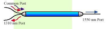
50 Description of a WDM. 50
51 Building a Fiber Optic Link for a Broadband System. One optical transmitter can supply signal to one or many NODE. If one transmitter is feeding many NODE, the fiber link will require the use of optical splitter or coupler nm MHz 5-40 MHz NODE NODE NODE NODE You need to calculate the loss of each coupler, so each NODE will l receive the right input. 51

52 Building a Fiber Optic Link for a Broadband System. The loss in % and db of the dual wave ( nm) of optical splitter & coupler. 50 / 50 % 3.6 / 3.6 db 55 / 45 % 3.2 / 4.1 db 60 / 40 % 2.7 / 4.7 db 65 / 35 % 2.3 / 5.3 db 70 / 30 % 2.2 / 5.7 db 75 / 25 % 1.8 / 6.8 db 80 / 20 % 1.3 / 7.8 db 85 / 15 % 1.0 / 9.2 db 90 / 10 % 0.8 / 11.2 db 95 / 5 % 0.5 / 14.4 db In most cases, you will need to add the fusion splices to these loss. 52
53 Building a Fiber Optic Link for a Broadband System. Using 1 transmitter for 3 optical NODE using optical couplers. Forward signal 1310 nm at Optical NODE. 0.4 db loss / 1310 nm Optical Coupler Optical Coupler 8.0 km 7.3 km 9.0 km db loss db loss db loss dbm dbm dbm Return signal 1310 nm from Optical NODES Notice here, that I am using 0.4 db loss / km at 1310 nm, when the t actual loss is 0.33 db / km. By using this as the actual loss, I do not have to calculate the extra loss for connectors and fusion splicing in the optical link. 53
54 Building a Fiber Optic Link for a Broadband System. The right optical power input required at each NODE. In a modern system each NODE require an input of : 1.0 to +2.0 dbm. We should always try to hit the receiver at 0.0 dbm. With this level l and modern DFB (Distributed Feed Back) laser, the NODE,s technical specification n should be: C/N: db for 77 channels in CW mode. CTB: db for 77 channels in CW mode. CSO: db for 77 channels in CW mode. Reducing the number of carried channels from 77 to 40, will increase the Carrier to Noise specification by 3.0 db, but will not better the CTB and CSO C specification. Every db away from 0.0 dbm input, will increase or decrease the C/N by one db. Then a 1.0 dbm input will give db C/N and a +2.0 dbm will give a db C/N. We should never hit a NODE with more than +2.0 dbm input. Optical input i signal above +2.0 dbm will either shorten the receiving photo diode s life l or will get the NODE to go into distortion. 54
55 Building a Fiber Optic Link for a Broadband System. The right number of return signal from NODE; Ideally every NODE should have it own return sent directly to the e CMTS. Because of cost and to-day need, the industry is now presently mixing four (4) return signal from NODE per combining network. From NODE - 1 From NODE - 2 From NODE - 3 From NODE

56 Building a Fiber Optic Link for a Broadband System. Broadband Combining Network Forward RF Combiner Rear of unit Common Return RF Combiner Rear of unit Common Sweep Rx NODE 5-42 MHz Fiber optic Return 5-40 MHz Fiber optic Forward MHz MHz Monitoring System Optical Equipment Coaxial Cable Return 5-40 MHz Coaxial Cable Forward MHz MHz Return Alignment and Ingress Control System Headend Equipment Cablemodem IP-Telephone / 73.5 MHz Forward Tx Sweep MHz Sweep Rx 56
57 Fiber Optic Cable. We will comes back to the technology fiber optic later on, in the seminar. 57
58 TEST! 58
59 Name two types of signal a coaxial cable can carry? What is the impedance of coaxial cable used in a HFC system? Name the two types of coaxial cable used for a HFC system in North America? What is the maximum and minimum temperature coaxial cable are spec at? What type of AC wave comes out of a power supply used in a HFC system? s Name two types of passives equipment used in a HFC system? How many types of multitap can we used in a HFC system? 59
60 60
This presentation will give you a general idea of the subjects on the 18 CATV-HFC seminars that are available from:
 This presentation will give you a general idea of the subjects on the 18 CATV-HFC seminars that are available from: 1 Broadband System - A Satellites are spaced every 2nd degrees above earth "C" Band Toward
Broadband System - K
 Broadband System - K Satellites are spaced every 2nd degrees above earth "C" Band Toward satellite 6.0 GHz Toward earth 4.0 GHz "L" Band Toward satellite 14.0 GHz Toward earth 12.0 GHz TV TRANSMITTER Headend
Introduction to Fiber Optic Cable Technology Jerry Bednarczyk, PE Course Content
 Introduction to Fiber Optic Cable Technology Jerry Bednarczyk, PE Course Content Page 1 of 10 GENERAL A fiber optic cable system is very similar to a copper wire system in that it is used to transmit data
AN INTRODUCTION TO FIBER OPTICS SYSTEMS - PART II
 AN INTRODUCTION TO FIBER OPTICS SYSTEMS - PART II BASIC SYSTEM DESIGN This series of articles on Fiber Optics plan to introduce the reader to the use of Fiber Optics in CATV Networks. Part 1 of the article
OmniStar GX2 Headend Optics Platform
 arris.com OmniStar GX2 Headend Optics Platform GX2 EM1000 Series 1550 nm Broadcast Transmitter FEATURES Provides full performance 50 1002 MHz forward bandwidth for mixed analog and digital loading Versions
CABLE TV on fiber. CABLE TV FIBERLINK Pass 100+ TV channels on 1 SingleMode fiber with no need for amps
 #FBS-870R-WALL-econ Reasonable prices, priceless reasoning. CABLE TV on fiber CABLE TV FIBERLINK Pass 100+ TV channels on 1 fiber with no need for amps Combine dozens of analog and digital channels in
OPTILAB CATALOG TRANSMITTER OPTICAL NODE MINI-NODE EDFA PASSIVE OPTICS RECEIVER
 OPTILAB CATALOG END-TO-END LASERS AND FIBER OPTIC PRODUCTS FOR RFOG, HFC, PON, DEEP FIBER 2013 Q3 OPTILAB CATALOG RUS & USDA ACCEPTED PRODUCTS VERSATILE AND EXCELLENT TRANSMISSION SOLUTIONS FOR HFC, RFOG,
MIGRATION TO FULL DIGITAL CHANNEL LOADING ON A CABLE SYSTEM. Marc Ryba Motorola Broadband Communications Sector
 MIGRATION TO FULL DIGITAL CHANNEL LOADING ON A CABLE SYSTEM Marc Ryba Motorola Broadband Communications Sector ABSTRACT Present day cable systems run a mix of both analog and digital signals. As digital
Selection of a cable depends on functions such as The material Singlemode or multimode Step or graded index Wave length of the transmitter
 Fibre Optic Communications The greatest advantage of fibre cable is that it is completely insensitive to electrical and magnetic disturbances. It is therefore ideal for harsh industrial environments. It
LaserPXIe Series. Tunable Laser Source PRELIMINARY SPEC SHEET
 -1002 1000 Series Tunable Laser Source PRELIMINARY SPEC SHEET Coherent Solutions is a Continuous Wave (CW), tunable laser source offering high-power output, narrow 100 khz linewidth and 0.01 pm resolution
Challenges of Launching DOCSIS 3.0 services. (Choice s experience) Installation and configuration
 Installation and configuration") (Choice s experience) Installation and configuration (cont.) (Choice s experience) DOCSIS 3.0 Components M-CMTS deployment DTI Server Edge QAM Modular CMTS I-CMTS Integrated CMTS Integrated DOCSIS 3.0
(Choice s experience) Installation and configuration (cont.) (Choice s experience) DOCSIS 3.0 Components M-CMTS deployment DTI Server Edge QAM Modular CMTS I-CMTS Integrated CMTS Integrated DOCSIS 3.0
Introduction. Fiber Optics, technology update, applications, planning considerations
 2012 Page 1 Introduction Fiber Optics, technology update, applications, planning considerations Page 2 L-Band Satellite Transport Coax cable and hardline (coax with an outer copper or aluminum tube) are
Bravo AV s Structured or Whole-House Wiring Approach
 Custom Audio & Video Systems: Design and Installation Bravo AV s Structured or Whole-House Wiring Approach THE QUALITY OF THE CABLE YOU USE IS CRITICALLY IMPORT TO THE PERFORMANCE OF YOUR SYSTEM Introduction
OPTICAL DISTRIBUTION STATION -
 optical distribution station is a high performance, four individual outputs node. With high output levels and performance to 862MHz, it provides an ideal platform for support of the evolving technologies
DVO700 P FIBRE OPTIC TRANSMITTER
 Timo Rantanen September 24, 2002 1(5) FIBRE OPTIC TRANSMITTER is a high performance, extremely linear externally modulated 1550 nm transmitter for DVO fibre optic CATV link. This transmitter type has been
Overcoming Nonlinear Optical Impairments Due to High- Source Laser and Launch Powers
 Overcoming Nonlinear Optical Impairments Due to High- Source Laser and Launch Powers Introduction Although high-power, erbium-doped fiber amplifiers (EDFAs) allow transmission of up to 65 km or more, there
FORWARD PATH TRANSMITTERS
 CHP Max FORWARD PATH TRANSMITTERS CHP Max5000 Converged Headend Platform Unlock narrowcast bandwidth for provision of advanced services Economical and full-featured versions Low profile footprint allows
Optical Fiber Link, 0.1~ 20 GHz RF Over Fiber, I-IFLRF12
 Fiber Link, 0.1~ 20 GHz RF Over Fiber, I-IFLRF12 Our I-IFLRF20 series is a wideband RF over fiber link that provides optical transport of RF signals in radars, satcom, EW/ECM and other antenna remoting
Proposal of Distributing 4 SAT IF Signals To 209 Homes within 3Km Over Fiber Cable
 Proposal of Distributing 4 SAT IF Signals To 209 Homes within 3Km Over Fiber Cable Shufeng Yang Greatway Technology Co., Ltd Web: www.greatwaytech.com Contents 1.0 Project Description 2.0 Project Schedule
Catv Expert
 My way of chasing INGRESS and NOISE on the return path of a CATV-HFC system. J. A. André (Andy) Lamarre Senior member SCTE (USA). Catv Expert http://www.catvexpert.com Before we get going on this subject,
Cable Jacket - The outermost layer of the fiber cable. Application: Types Single mode Multi mode. Simplex or Duplex available
 Fiber Optic Products FIBER OPTIC PRODUCTS FIBER OPTIC PATCH CORD CABLE The Construction of a Fiber-Optic Cable Cable Jacket - The outermost layer of the fiber cable. Strengthening fibers - The strengthening
XCOM1002JE (8602JE) Optical Receiver Manual
 Optical Receiver Manual") XCOM1002JE (8602JE) Optical Receiver Manual - 2 - 1. Product Summary XCOM1002JE (8602JE) outdoor optical receiver is our latest 1GHz optical receiver. With wide range receiving optical power, high output
XCOM1002JE (8602JE) Optical Receiver Manual - 2 - 1. Product Summary XCOM1002JE (8602JE) outdoor optical receiver is our latest 1GHz optical receiver. With wide range receiving optical power, high output
! "#$ ' % & % & ' ( )!' *!+, ( *-"(! './ 0 / 0/ $ 1/ 2$3 1
!' *!+, ( *-(! './ 0 / 0/ $ 1/ 2$3 1") ! "#$ ' %& %& ' ()!' *!+, (*- "(!'./0/0/ $1/2$3 1 1550 Fiber Transmitters 1550 nm External Modulation 4CHT8500AC (40~1GHz) 4CHT8500A 40~870 MHz) 1550nm External Modulation CATV Optic Transmitter Product
! "#$ ' %& %& ' ()!' *!+, (*- "(!'./0/0/ $1/2$3 1 1550 Fiber Transmitters 1550 nm External Modulation 4CHT8500AC (40~1GHz) 4CHT8500A 40~870 MHz) 1550nm External Modulation CATV Optic Transmitter Product
Product Classification. Dimensions. Environmental Specifications. General Specifications. Material Specifications. Mechanical Specifications
 E2O540JCASS-12CT MICFIBR-12.7MB MICFIBR-12.7MB DUCT DUCT E2O540JCASS- Product Classification Brand E 2 O E 2 O Coaxial/Fiber/Microduct Hybrid Buried Cable E O is a solution that enables service providers
TRFM Series RF Amplifier Module
 Doc. 2272065, Rev. C TIARRA Optical Node TRFM Series RF Amplifier Module Contents Equipment Description... 39 Model Names... 41 Functional Description... 43 Return RF Signal Flow... 45 Controls and Connectors...
TranScend Opto-Stacker & Destacker. Operation Manual
 TranScend Opto-Stacker & Destacker Operation Manual Although every effort has been taken to ensure the accuracy of this document it may be necessary, without notice, to make amendments or correct omissions.
TROUBLESHOOTING DIGITALLY MODULATED SIGNALS, PART 2 By RON HRANAC
 Originally appeared in the July 2006 issue of Communications Technology. TROUBLESHOOTING DIGITALLY MODULATED SIGNALS, PART 2 By RON HRANAC Digitally modulated signals are a fact of life in the modern cable
Description. Features MODEL ODN2P OPTICAL DISTRIBUTION NODE WITH TWO AMPLIFIED RF PORTS LIGHT LINK SERIES 2.
 MODEL ODN2P OPTICAL DISTRIBUTION NODE WITH TWO AMPLIFIED RF PORTS LIGHT LINK SERIES 2 Description Features The Light LinkB B Series 2 Optical distribution node with two amplified RF ports (ODN2P) has been
Optical Receiver Manual. Transmitter OP-OR212JSE. Shenzhen Optostar Optoelectronics Co., Ltd (Version 2)
") Optical Receiver Manual Transmitter OP-OR212JSE Shenzhen Optostar Optoelectronics Co., Ltd 2016. 7(Version 2) 1. Summary OP-OR212JSE optical receiver is the latest 1GHz dual-way switch optical receiver.
Optical Receiver Manual Transmitter OP-OR212JSE Shenzhen Optostar Optoelectronics Co., Ltd 2016. 7(Version 2) 1. Summary OP-OR212JSE optical receiver is the latest 1GHz dual-way switch optical receiver.
Model GS Port Node 1 GHz with 65/86 MHz split
 Model GS7000 4-Port Node 1 GHz with 65/86 MHz split The Model GS7000 4-Port Node is our latest generation 1 GHz optical node platform and utilizes a completely new housing designed for optimal heat dissipation.
MULTIDYNE INNOVATIONS IN TELEVISION TESTING & DISTRIBUTION DIGITAL VIDEO, AUDIO & DATA FIBER OPTIC MULTIPLEXER TRANSPORT SYSTEM
 MULTIDYNE INNOVATIONS IN TELEVISION TESTING & DISTRIBUTION INSTRUCTION MANUAL DVM-1000 DIGITAL VIDEO, AUDIO & DATA FIBER OPTIC MULTIPLEXER TRANSPORT SYSTEM MULTIDYNE Electronics, Inc. Innovations in Television
FiberLink 7142 Series
 MANUAL FiberLink 7142 Series 4 Channels of Composite Video and 8 Channels of Audio over one single mode or multimode fiber Installation and Operations Manual WWW.ARTEL.COM FibeLink 7142 Series Contents
SPECIAL SPECIFICATION 6559 Telecommunication Cable
 2004 Specifications CSJ 0015-09-147, etc. SPECIAL SPECIFICATION 6559 Telecommunication Cable 1. Description. This specification governs the materials, installation, termination, splicing, testing, training,
VersiVision. FVTM4BCxA-CE / FVRM4BCxA-CE MULTIPLEXER SYSTEM 4-CHANNELS DIGITALLY ENCODED VIDEO 2-CHANNELS BI-DIRECTIONAL DATA
 VersiVision FVTM4BCxA-CE / FVRM4BCxA-CE MULTIPLEXER SYSTEM 4-CHANNELS DIGITALLY ENCODED VIDEO 2-CHANNELS BI-DIRECTIONAL DATA 4-CHANNELS BI-DIRECTIONAL AUDIO 4-CHANNELS BI-DIRECTIONAL CONTACT CLOSURE 1-CHANNEL
FIM-108 MATRIX FIBER INTERFACE INSTRUCTION MANUAL
 FIM-108 MATRIX FIBER INTERFACE INSTRUCTION MANUAL FIM-108 Matrix Fiber Interface Instruction Manual 2003 Clear-Com Intercom Systems All Rights Reserved Part Number 810291 Rev. A Clear-Com Intercom Systems
WDM Video Overlays on EFM Access Networks
 WDM Video Overlays on EFM Access Networks David Piehler Harmonic, Inc. Broadband Access Networks IEEE 802.3ah January 2002 meeting Raleigh, North Carolina david.piehler@harmonicinc.com 1 Main points of
75 Ohm N Male Connector Crimp/Solder Attachment for RG6
 75 Ohm N Male Connector Crimp/Solder Attachment for RG6 RF Connectors Technical Data Sheet PE4508 Configuration N Male Connector 75 Ohms Straight Body Geometry Features Max Operating Frequency 15 GHz Good
How Wire Fails Originally presented to the Society of Motion Picture and Television Engineers Convention, Sydney, Australia, on Friday, July 4, 1997.
 How Wire Fails Originally presented to the Society of Motion Picture and Television Engineers Convention, Sydney, Australia, on Friday, July 4, 1997. ABSTRACT: By Stephen H. Lampen Technology Development
Directional Couplers and Splitters
 Directional couplers and splitters divide trunk and feeder lines. 17-Amp current handling capacity. Excellent hum-modulation performance. 1/2-inch hard-line ports have extra length, creating a better seal
BALANCING THE REVERSE PATH
 BALANCING THE REVERSE PATH A good Reverse Path is essential for broadband delivery on a cable network. This article takes a closer look at the Reverse Path and provides tips on setting up the Reverse Path
SECTION 7 -- CROSS-CONNECT SYSTEMS
 DETAIL ENGINEERING REQUIREMENTS AT&T March, 2016 Section 7, ATT-TP-76400 Revised NA SECTION 7 -- CROSS-CONNECT SYSTEMS CONTENTS PAGE 1. GENERAL... 7-2 1.1. Introduction... 7-2 1.2. Cable Holes... 7-2 1.3.
Table of Contents. Headend Optical Transport OmniStar Enhanced DFB Laser [AM-OMNI-ALM-*] file:////ncs-server-xp/temp/motorola CD 2001/frames.
![Table of Contents. Headend Optical Transport OmniStar Enhanced DFB Laser [AM-OMNI-ALM-*] file:////ncs-server-xp/temp/motorola CD 2001/frames.](/thumbs/93/111058212.jpg "Table of Contents. Headend Optical Transport OmniStar Enhanced DFB Laser [AM-OMNI-ALM-*] file:////ncs-server-xp/temp/motorola CD 2001/frames.") Table of Contents Headend Optical Transport OmniStar Enhanced DFB Laser [AM-OMNI-*] file:////ncs-server-xp/temp/motorola CD 2001/frames.htm (1 of 5) [7/8/2009 8:23:40 AM] FEATURES 870 MHz passband: up
Table of Contents Headend Optical Transport OmniStar Enhanced DFB Laser [AM-OMNI-*] file:////ncs-server-xp/temp/motorola CD 2001/frames.htm (1 of 5) [7/8/2009 8:23:40 AM] FEATURES 870 MHz passband: up
Professionally Install Products Right the First Time. TOOL-CRIMP Radial Linear compression tool for BNC, F & RCA connectors
 Professionally Install Products Right the First Time Profit with PROFIT Tributaries PROFIT System ProFit System employs radial compression technology which preserves the coaxial cables critical 75 ohm
SPECIAL SPECIFICATION 8540 Telecommunication Cable
 2004 Specifications CSJ 0914-00-307 & CSJ 0914-25-003 SPECIAL SPECIFICATION 8540 Telecommunication Cable 1. Description. This specification governs the materials, installation, termination, splicing, testing,
EVLA Fiber Selection Critical Design Review
 EVLA Fiber Selection Critical Design Review December 5, 2001 SJD/TAB 1 Fiber Selection CDR Decision about what fiber to install Select cable Jan 2002 Order cable Jan 2002 Receive cable May 2002 Start installation
HDO701 FIBRE OPTIC TRANSMITTER
 Timo Rantanen 12.7.2011 1(5) HDO701 FIBRE OPTIC TRANSMITTER HDO701 is a high performance, extremely linear externally modulated 1550 nm transmitter for fibre optic CATV links. This transmitter type has
VersiVision. FVTMHA0xA / FVRMHA0xA 16-CHANNEL DIGITALLY ENCODED VIDEO 1-CHANNEL BI-DIRECTIONAL DATA MULTIPLEXER USER S MANUAL.
 VersiVision FVTMHA0xA / FVRMHA0xA 16-CHANNEL DIGITALLY ENCODED VIDEO 1-CHANNEL BI-DIRECTIONAL DATA MULTIPLEXER USER S MANUAL Revision B April 2013 VERSITRON, Inc. 83 Albe Drive / Suite C Newark, DE 19702
CPON-HFC. Customer Premises Optical Node for FTTH networks. About the Product
 About the Product The Light Link Direct CPON-HFC customer premises optical node for FTTH networks offers full-bandwidth cable television delivery, plus broadband access via DOCSIS cable modems. Fibre-to-the-home
Module 11 : Link Design
 Module 11 : Link Design Lecture : Link Design Objectives In this lecture you will learn the following Design criteria Power Budget Calculations Rise Time Budget Calculation The optical link design essentially
ULTIMATE SNAP-N-SEAL
 ULTIMATE SNAP-N-SEAL F Series Compression Connectors Thomas & Betts introduces the Ultimate Snap-N-Seal Compression Connector, the newest addition to the Snap-N-Seal system. Look for the classic design
Critical Benefits of Cooled DFB Lasers for RF over Fiber Optics Transmission Provided by OPTICAL ZONU CORPORATION
 Critical Benefits of Cooled DFB Lasers for RF over Fiber Optics Transmission Provided by OPTICAL ZONU CORPORATION Cooled DFB Lasers in RF over Fiber Optics Applications BENEFITS SUMMARY Practical 10 db
VersiVision. FVTM2BBxA / FVRM2BBxA 2-CHANNELS DIGITALLY ENCODED VIDEO 2-CHANNELS BI-DIRECTIONAL DATA 2-CHANNELS BI-DIRECTIONAL AUDIO
 VersiVision FVTM2BBxA / FVRM2BBxA 2-CHANNELS DIGITALLY ENCODED VIDEO 2-CHANNELS BI-DIRECTIONAL DATA 2-CHANNELS BI-DIRECTIONAL AUDIO TRANSMITTER / RECEIVER MULTIPLEXERS USER S MANUAL Revision B April 2013
Measurement of Television Channel Levels on CATV Networks
 Measurement of Television Channel Levels on CATV Networks D E Woollard, SCTE Papers Committee Chairman 21st January 1999 1. Introduction Traditionally the measurement of Television channels has been concerned
SPECIFICATION 96F SM LOOSE TUBE, DRY CORE MINI CABLE
 Revision No.:01 Date: 07.10.06 SPECIFICATION OF 96F SM LOOSE TUBE, DRY CORE MINI CABLE PART NO.:D-96/SM/MTY(F)-MFN-O6.3 Checked By: Pavan Maheshwari Process Associate Design & Development Team Approved
99 Washington Street Melrose, MA Fax TestEquipmentDepot.com OPERATION MANUAL. The Best Thing on Cable
 99 Washington Street Melrose, MA 02176 Fax 781-665-0780 TestEquipmentDepot.com OPERATION MANUAL The Best Thing on Cable Table of Contents INDEX I General Information Introduction... 3 Features: RSVP 2
Optical Communications Mainframe - Laser Transmitter Module
 About the Product The LTM13 Multi Quantum Well (MQW) Distributed Feedback (DFB) laser transmitter module has been designed for cable television and HFC broadband applications. The LTM13 module easily fits
Advanced Test Equipment Rentals ATEC (2832)
") E stablished 1981 Advanced Test Equipment Rentals www.atecorp.com 800-404-ATEC (2832) Technical Datasheet Scalar Network Analyzer Model 8003-10 MHz to 40 GHz The Giga-tronics Model 8003 Precision Scalar
E stablished 1981 Advanced Test Equipment Rentals www.atecorp.com 800-404-ATEC (2832) Technical Datasheet Scalar Network Analyzer Model 8003-10 MHz to 40 GHz The Giga-tronics Model 8003 Precision Scalar
Cisco GS MHz 4-Way Segmentable Node
 Data Sheet Cisco GS7000 1218-MHz 4-Way Segmentable Node Product Description Consumer bandwidth demand continues to grow at a rapid rate every year. As a result, cable operators with devices based on DOCSIS
IQOTXD Dual-Channel Multimode Fibre Optic Transmitter for SDI
 Dual-Channel Multimode Fibre Optic Transmitter for SDI CC Module Description The is a dual-channel multimode fibre optic transmitter for SDI. The unit takes two inputs of SDI at 270 Mbits/s and provides
Multicom Optical Return Path Receiver MUL HRPR 4B
 Multicom Optical Return Path Receiver User Manual v.9 www.multicominc.com 800 423 2594 407 331 7779 1076 Florida Central Parkway, Longwood, FL 32750 SAFETY NOTIFICATION Multicom strongly advises you to
THE EFFECT OF LOOSE CONNECTORS ON SHIELDING EFFECTIVENESS
 THE EFFECT OF LOOSE CONNECTORS ON SHIELDING EFFECTIVENESS Asheridge Communications (A Teleste PLC Company) has undertaken a study to further understand the issues of RFI (Radio Frequency Interference)
FiberLink 3500 Series Transceivers
 MANUAL FiberLink 3500 Series Transceivers 2 or 4 Channel 3G/HD/SD-SDI Transmission over one or two single mode or multimode fibers Installation and Operations Manual WWW.ARTEL.COM Contents Contents Welcome...
6 3 0 N M, S I N G L E M O D E F U S E D F I B E R O P T I C C OUPLERS / TA P S
 6 3 0 N M, S I N G L E M O D E F U S E D F I B E R O P T I C C OUPLERS / TA P S Narrowband and Wideband Couplers for 630 nm Available with 50:50, 75:25, 90:10, or 99:1 Terminated with 2.0 mm Narrow Key
Traditional RF Splitter/Combiner and Directional Coupler User Manual
 Traditional RF Splitter/Combiner and Directional Coupler User Manual Content Page INTRODUCTION... 1 Revision History... 2 Trademark Information... 2 Admonishments... 2 General Safety Precaution... 2 1
Amplifiers STARLINE 2000 Broadband Telecommunications Distribution Amplifier [BT*/*]
![Amplifiers STARLINE 2000 Broadband Telecommunications Distribution Amplifier [BT*/*]](/thumbs/84/89282316.jpg "Amplifiers STARLINE 2000 Broadband Telecommunications Distribution Amplifier [BT*/*]") mplifiers STRLINE 2000 Broadband Telecommunications Distribution mplifier [BT*/*] FETURES 750 MHz and 870 MHz power doubling technology in Gas or silicon 60/0V powering Meets IEEE C62.41 11 and BellCore
mplifiers STRLINE 2000 Broadband Telecommunications Distribution mplifier [BT*/*] FETURES 750 MHz and 870 MHz power doubling technology in Gas or silicon 60/0V powering Meets IEEE C62.41 11 and BellCore
SPECIFICATION 192F SM LOOSE TUBE, DRY CORE MINI CABLE
 Revision No.:00 Date: 08.03.2010 SPECIFICATION OF 192F SM LOOSE TUBE, DRY CORE MINI CABLE PART NO.:D-192/SM/MTY(F)-MFN-O9.1 Checked By: Pavan Maheshwari Process Associate Design & Development Team Approved
RLT 1550 d10. DWDM High Power, Ultra Wide Band CATV & SAT MHz Laser Optical Transmitter, with pre-correction, LAN remote control and alarms
 RLT 1550 d10 DWDM High Power, Ultra Wide Band CATV & SAT 47-2.700 MHz Laser Optical Transmitter, with pre-correction, LAN remote control and alarms The ultra wide band, 47-2.700 MHz, optical, laser transmitter,
SPECIAL SPECIFICATION 1291 Fiber Optic Video Data Transmission Equipment
 1993 Specifications CSJ 0500-01-117 SPECIAL SPECIFICATION 1291 Fiber Optic Video Data Transmission Equipment 1. Description. This Item shall govern for the furnishing and installation of Fiber Optic Video
ENGINEERING COMMITTEE Interface Practices Subcommittee AMERICAN NATIONAL STANDARD ANSI/SCTE
 ENGINEERING COMMITTEE Interface Practices Subcommittee AMERICAN NATIONAL STANDARD ANSI/SCTE 48-3 2011 Test Procedure for Measuring Shielding Effectiveness of Braided Coaxial Drop Cable Using the GTEM Cell
SPECIAL SPECIFICATION 6911 Fiber Optic Video Data Transmission Equipment
 2004 Specifications CSJ 3256-02-079 & 3256-03-082 SPECIAL SPECIFICATION 6911 Fiber Optic Video Data Transmission Equipment 1. Description. Furnish and install Fiber Optic Video Data Transmission Equipment
TECHNICAL SPECIFICATION
 ISSUED : OCT. 02, 2006 PAGE : 1 OF 9 REV. : 1 TECHNICAL SPECIFICATION FOR GST 2006-043A LOOSE TUBE DRY CORE CABLE SINGLE JACKET/SINGLE ARMOR (SJSA CABLE) Prepared By : Oh-Heoung Kwon Engineer Optical Technical
COMMON WORK RESULTS FOR INTEGRATED AUTOMATION DESIGN AND CONSTRUCTION STANDARD
 PART 1: GENERAL 1.01 Purpose: A. This standard is intended to provide useful information to the Professional Service Provider (PSP) to establish a basis of design. The responsibility of the engineer is
High Density Optical Platform for FTTx and HFC
 High Density Optical Platform for FTTx and HFC Optical Platform for FTTx and HFC The WISI optical platform Optopus is a highly flexible and high density platform for all kinds of analog optical networks.
Traditional RF Splitter/Combiner and Directional Coupler User Manual
 Traditional RF Splitter/Combiner and Directional Coupler User Manual Content Page INTRODUCTION... 1 Revision History... 2 Trademark Information... 2 Admonishments... 2 General Safety Precaution... 2 1
2015 OPTICAL TRANSMITTERS
 2015 OPTICAL TRANSMITTERS Released V H Mar 15 SATELLITE AND TERRESTRIAL OPTICAL BROADCAST EQUIPMENT DVB is a registered trademark of the DVB Project A DVA NCE D TECHNOLOGY FOR PROFESSIONAL BROADCASTING
IQORXD Dual-Channel Multimode Fibre Optic Receiver for SDI
 Dual-Channel Multimode Fibre Optic Receiver for SDI CC Module Description The is a dual-channel fibre optic receiver for SDI. The unit takes two Multi-Mode optical inputs in accordance with SMPTE 297M
Fibre Optic Cable & Connector Guide
 Fibre Optic Cable & Connector Guide White paper White Paper Fibre Optic Cable & Connector Guide v1.0 EN 1 Introduction Organising through cables and connectivity options can be an exasperating exercise.
CHP Max Headend Optics Platform CHP CORWave II
 CHP Max Headend Optics Platform CHP CORWave II 1 GHz C Band DWDM Forward Transmitters FEATURES Consolidation or elimination of OTNs and node splitting by harvesting plant assets with up to 16 full spectrum
Introduction to Fibre Optics
 Introduction to Fibre Optics White paper White Paper Introduction to Fibre Optics v1.0 EN 1 Introduction In today s networks, it is almost impossible to find a network professional who has never been in
Model DM8000-U Optical Transmitter Direct Modulation, DWDM, Low Distortion, Wideband
 Model DM8000U Optical Transmitter Direct Modulation, DWDM, Low Distortion, Wideband Applications Video signal distribution to HFC CATV and FTTP nodes 1527 Supports CATV, QAM, and DBS signal carriage Replacement
Radio Frequency over Glass. Passive Optical Network (PON) for EuroDOCSIS infrastructures
 for EuroDOCSIS infrastructures") Radio Frequency over Glass Passive Optical Network (PON) for EuroDOCSIS infrastructures Radio Frequency over Glass (RFoG) Because RFoG extends the range of glass-fibre networks to buildings (FttB) and
Radio Frequency over Glass Passive Optical Network (PON) for EuroDOCSIS infrastructures Radio Frequency over Glass (RFoG) Because RFoG extends the range of glass-fibre networks to buildings (FttB) and
APPENDIX D TECHNOLOGY. This Appendix describes the technologies included in the assessment
 APPENDIX D TECHNOLOGY This Appendix describes the technologies included in the assessment and comments upon some of the economic factors governing their use. The technologies described are: coaxial cable
L-Band Fiber Optic Links
 L-Band Fiber Optic Links Features & Benefits L-Band: 950 3000MHz Up to 10Km distance Wide input power suitable for both Uplink and Downlink applications Powerful management capabilities via a front panel
IF and L-Band Fiber Optic Links. Performance Highlights
 FSS70F6Twall IF and LBand Fiber Optic Links The fiberoptic interfacility links (IFLs) are a highperformance, costeffective alternative to coaxial cable for 10 MHz to 200 MHz IF and 950 MHz to 2050 MHz
Fiber Optic. Foreword. Special Tips:
 Foreword This manual applies to 1310nm AM direct modulated optical transmitter with SNMP network management interface. It mainly describes the performance characteristics, technical parameters, installation
Cisco 1.25 GHz Surge-Gap Passives
 Data Sheet Cisco 1.25 GHz Surge-Gap Passives The Cisco 1.2 GHz Surge-Gap Passives product line is the latest evolution of the HFC network providing full support of the DOCSIS 3.1 standard. DOSCIS 3.1 support
384A Adapter Installation Instructions
 Instruction Sheet 860237684 Issue 9, October 2012 SYSTIMAX Solutions 384A Adapter Installation Instructions General The 384A adapter (Figure 1) is a broadband video adapter that provides connectivity to
ENGINEERING COMMITTEE Interface Practices Subcommittee AMERICAN NATIONAL STANDARD ANSI/SCTE
 ENGINEERING COMMITTEE Interface Practices Subcommittee AMERICAN NATIONAL STANDARD ANSI/SCTE 86 2010 SCTE Recommended Optical Fiber Cable Types for Outside Plant Trunk and Distribution Applications NOTICE
Fiber Optics Redefined
 Fiber Optics Redefined Questions and Answers on the basics of fiber optic installation TECHLOGIX NETWORX Questions & Answers Questions and Answers Q: What are the two main types of fiber? A: The two main
7840A DOCSIS 3.1 Low Noise CATV Optical Receiver
 The 7840A DOCSIS 3.1 Low Noise CATV Optical Receiver is a single-mode fiber pigtailed module featuring a low-noise, impedance-matched broadband photodiode and RF amplification. The device receives optical
Fiber Broadband Network Systems
 Fiber Broadband Network Systems Hai-Han Lu ( 呂海涵 ) hhlu@ntut.edu.tw National Taipei University of Technology Institute of Electro-Optical Engineering Outline Broadband Introduction Principles CATV / Fiber
Alternative Fiber Coupler Options
 980 NM, SINGLE MODE FUSED FIBER OPTIC COUPLERS / TAPS Narrowband and Wideband Couplers for 980 nm 50:50, 75:25, 90:10, or 99:1 Coupling Ratio Polarization Insensitive Combine or "Tap Off" Signals FC980-50B-APC
LT1550 Laser Transmitter with Erbium Doped Fibre Amplifier
 About the Product The Light Link Series 2 optical transmitter model LT1550 employs a high performance thermally stabilised, DFB, low-chirp, isolated laser to transmit CATV signals. Operating on a specific
SATCOM FIBER OPTIC PRODUCTS
 INDOOR APPLICATIONS ONE THIRD RACK SATCOM FIBER OPTIC PRODUCTS CARD CAGE RACK OUTDOOR APPLICATIONS DC-POWERED L-BAND C-BAND LNA TABLE OF CONTENTS INDOOR EQUIPMENT Page One third rack links 2 One third
Model 755U Optical Transmitter DWDM, up to 20 km, Low Distortion, Wideband
 Model 755U Optical Transmitter DWDM, up to 20 km, Low Distortion, Wideband Emcore s Model 755U is a directly modulated (DM) DWDM optical transmitter specifically designed for wideband applications that
OMNISTAR GX2. GX2-LM1000E Series 1310 nm Broadcast Transmitter DATA SHEET BENEFITS. 1 GHz bandwidth
 DATA SHEET BENEFITS OMNISTAR GX2 GX2-LM1000E Series 1310 nm Broadcast Transmitter 1 GHz bandwidth High module density up to 16 transmitter modules in a 4 RU housing High performance: Advanced predistortion
MAXCOM PRODUCT SPECIFICATIONS FIBER OPTIC VIDEO / AUDIO / ASI LINK. Model MX3257HD. Description. Features. Model Selection Guide
 MAXCOM PRODUCT SPECIFICATIONS FIBER OPTIC VIDEO / AUDIO / ASI LINK Model MX3257HD Description The rack-mountable MX3257HD fiber optic video multiplexer is ideal for transmitting 1 channel of video, 2 channels
D-COAX, Inc. D-COAX d086 Series Cable Pair. High Frequency, Skew Matched, Phase Stable Cable Pair (65 GHz)
") D-COAX, Inc. D-COAX d086 Series Cable Pair High Frequency, Skew Matched, Phase Stable Cable Pair (65 GHz) D-COAX d086 Series Cable Pair consists of two skew matched (to 1ps) flexible cable assemblies with
D-COAX, Inc. D-COAX d086 Series Cable Pair High Frequency, Skew Matched, Phase Stable Cable Pair (65 GHz) D-COAX d086 Series Cable Pair consists of two skew matched (to 1ps) flexible cable assemblies with
SatellitePlus Model OLAT/OLAR. Advanced L-Band Series. 10-4,000 MHz OPERATING MANUAL
 SatellitePlus Model OLAT/OLAR Advanced L-Band Series 10-4,000 MHz OPERATING MANUAL 24926 Highway 108 Sierra Village, CA 95346 Phone: (800) 545-1022 Fax: (209 586-1022 025-000570 Rev. X7 E-Mail: sales@olsontech.com
ENGINEERING COMMITTEE Interface Practices Subcommittee AMERICAN NATIONAL STANDARD ANSI/SCTE
 ENGINEERING COMMITTEE Interface Practices Subcommittee AMERICAN NATIONAL STANDARD ANSI/SCTE 132 2012 Test Method For Reverse Path (Upstream) Bit Error Rate NOTICE The Society of Cable Telecommunications