Status of the SNS Linac: An Overview N. Holtkamp for the SNS Collaboration ORNL, Oak Ridge, TN 37830, USA
|
|
|
- Steven McBride
- 6 years ago
- Views:
Transcription

1 Lübeck, August 20, 2004 Status of the SNS Linac: An Overview N. Holtkamp for the SNS Collaboration ORNL, Oak Ridge, TN 37830, USA
")
2 SNS is the Forefront Facility for Future High Beam Power Accelerators Highest Beam Power worldwide under construction Stepping stone to next generation Spallation Sources The SNS will begin operation in 2006 At 1.4 MW it will be ~8x ISIS, the world s leading pulsed spallation source The peak thermal neutron flux will be ~50-100x ILL 5000 hours per year at an availability of >90%!!!!!!!!!!! (~ in 2009)

3 The Spallation Neutron Source Partnership Description Accelerator Project Support 75.6 Front End Systems Linac Systems Ring & Transfer System Target Systems Instrument Systems 63.3 Conventional Facilities Integrated Control Syst BAC 1,164.4 Contingency 28.3 TEC 1,192.7 R&D Pre-Operations TPC 1, At peak : ~500 People worked on the construction of the SNS accelerator SNS-ORNL Accelerator systems: ~167 M$ ~177 M$ ~60 M$ ~20 M$ ~63 M$ ~106 M$ ~113 M$ Oak Ridge, TN 35 49' N, 83 59' W

4 SNS Multilab Organizational Chart The Multi Lab Organization of SNS has brought an enormous amount of expertise to the table. It has made it easier to transition the required workforce in and out of the project. SNS is just one of several models that I m sure will be used to built large science projects in the future. The Multi Lab Org Chart for SNS is in many ways is not different than a typical one, but it does add a few layers of management.
5 Project Status Total cost is $1.4 B (US accounting), peaked in 2002 with $290 M. Project has costed or/and awarded almost $1.2B out of $1.4B Overall project design is 94% complete Overall the project is >84% complete (as of July) Within budget and schedule constraints ($1.4B and June 2006 completion) ES&H performance outstanding >5 million hours with one lost workday injury (combined hours worked for construction site and SNS/ORNL)

6 16 Instruments Now Formally Approved Fundamental Physics to Engineering Chemistry to Genomes to Life


7 Construction Nearing the End Target Front Building End Ring Building Tunnel Feb 2002 to Mai Linac 2002 Feb 2002

8 Major SNS Facility Parameters MHz 805 MHz Proton beam energy on target 1.0 GeV HEBT Proton beam RFQ current DTL on target 1.4 CCL ma SRF, β=0.61 SC linac SRF, output β=0.81 energy To1.0 GeV Ring HEBT length 170 m Power on target 1.4 MW Pulse Injector repetition 2.5 rate MeV 86.8 MeV MeV Accumulator Hz 387 MeV ring 1000 circ. MeV 248 m Ring fill time 1.0 ms Beam macropulse duty factor 6.0 % Ave. 1 RFQ Ring beam extraction gap 250 ns current in macro-pulse Medium-β ma Cryomodules - 3 Nb cavities each 6 DTL Tanks RTBT length 150 m H - peak current front end > High-β ma Cryomodules - 4 Nb cavities each 4 CCL Modules Protons per pulse on tgt 1.5x10 14 Chopper beam-on duty factor 68 % Proton pulse width on tgt 695 ns RFQ output energy 2.5 MeV Target material Liquid Hg FE + Linac length 335 m Weight of 1m 3 Hg 18 tons DTL output energy 87 MeV Energy per Pulse >17 kj CCL output energy 185 MeV Maximum # Instruments 24 AP Issue: Minimize losses along the accelerator chain!!!! 1 Watt per meter ( or 1 na) apart from collimators 1.0 GeV Ring Up to 1.3 GeV Lq Mercury Target


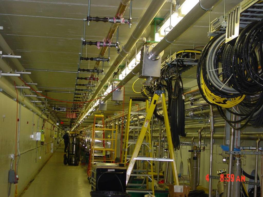
9 The SNS Ion Source Since Jan. 04 an SNS ion source is almost continuously in operation, 24/7, mostly unattended during nights and weekends. Since end of April 04 three runs have achieved a 6% and 5 runs a 7.4% duty cycle. All 8 runs were terminated after 1-2 weeks. No antenna failures have been detected. An operational run is typically terminated when the source output drops below ma. Front-End Temporary control room Hot Spare Stand Front-End Building
 50 45 40 35 30 25 20 15 10 5 1st Cesiation archiver down 36 kw LDF begin 2% oper 50 kw Source #3 begin 4% oper 2nd Cesiation 4th Cesiation 3rd")
10 The SNS Ion Source Typically the initial peak current exceeds the average current by ~30%. Average Beam Current (ma) st Cesiation archiver down 36 kw LDF begin 2% oper 50 kw Source #3 begin 4% oper 2nd Cesiation 4th Cesiation 3rd Cesiation 60 kw 5th Cesiation 0 31-May 2-Jun 4-Jun 6-Jun 8-Jun 10-Jun 12-Jun 14-Jun Date

11 LBNL: Design And Built Front End 2.5 MeV RFQ Ion Source


12 Drift Tube Linac Components DTL 1 in the tunnel Here it goes See S. Aleksandrov s Talk: WE 201 DTL 3

13 All DTLs MHz DTL designed at LANL Components built to spec in industry (plating at GSI) Assembled largely at ORNL All DTLs installed with 210 drift tubes in place. Operates at 1.3 x Kilpatrick max. Drift tubes have integrated permanent magnet quads 24 steering dipoles 10 beam position +phase monitors 12 beam loss monitors 6 beam current monitors 6 5 wire scanners 5 Faraday cups 12 neutron detectors
 P forward P")
14 Tank 3 Conditioned to Full Field and 40% Duty Factor in 30 hr! Increase P peak Increase P ave rf Power (kw) P forward P reflected

15 DTL 1-3 Commissioning: 40 MeV Can only run very short pulse and little beam power from now on. Beam Commissioned DTL1-3 in April 2004: Had beam through DTL3 36 hours after approval for operation: Achieved design 38 ma peak current 100% transmission
 Construction by")


16 Coupled-Cavity Linac (CCL) Construction by LANL done in Industry Contract awarded to Industry Hot model operated at 130% of peak field and 190% average power Bridge Coupler 44 final machining Segment 1-6 fiducial machining Cooling tests Production Segments

17 Coupled-Cavity Linac Deliveries Support September 2004 Commissioning Start 55 m long linac divided into 4 modules Designed at LANL, build and tuned in industry. Operates at 1.3 x Kilpatrick max. 48 quadrupoles and 32 steering magnets between segments. 10 beam position and phase monitors 28 beam loss monitors 1 current monitors 7 wire scanners 1 Faraday cups 3 bunch shape monitors 8 neutron detectors In Germany and here.
 @ 20Hz, 1ms after 5 x 12 hour")
18 CCL1 Module 1 Successfully RF Conditioned 100% Achieved: 2.5 MW (~120% of nominal 20Hz, 1ms after 5 x 12 hour shifts


19 HVCM Simplified Block Diagram RECTIFIER TRANSFORMER AND FILTERS SCR REGULATOR ENERGY STORAGE/SWITCHING BOOST TRANSFORMER HV RECTIFIER AND FILTER NETWORK 4mH 400A X3 -HV -HV -HV 10ohm 20mH.03uF CØ BØ 3Ø (ON/OFF) 6 EACH AØ BØ CØ.03uF.05uF VMON RTN 13.8KV 3Ø 50mH 6 EACH HV OUTPUT INPUT LINE CHOKE 5 th HARMONIC TRAP 7 th HARMONIC TRAP AØ 4mH 400A C SHUNT-PEAK RECTIFIER TRANSFORMER AND FILTERS SCR REGULATOR HIGH VOLTAGE CONVERTER/MODULATOR EQUIPMENT CONTROL RACK
20 HVCM Descritpion 11 HVCM out of 14 for the linac are installed. All 11 have been operated/tested. Combination of built to spec/built to print contract in industry. They have operated a total of ~8000 h at a variety of η with approximately 1500 at full load (η=7.5%). Depending on the klystron the operate between 75 and 115kV driving up to 12 klystrons in parallel. Have a very compact IGBT driven high Frequency (20kHz) converter with a compact polyphase transformer. The power density in the modulator compared to ~20 y ago went up by ~ x50.. Which has its challenges!


21 High-Power RF Installation Progress All RFQ / DTL HPRF Systems complete and operational. 2.5 MW MHz klystron with 2-3 per HVCM All four CCL systems are complete. 5 MW 805MHZ klystron with 1 per HVCM. 60 of 81 SCL klystrons installed. 550kW- 805MHz klystrons with typically 12 per HVCM. 2 SCL modulators tested All klystrons are made in industry in Europe and the US. 4 CCL 5 MW Klystron 60 klystrons out of 81 for sc linac in place 7 tubes turned over to operations

22 RF System / Modulator Configuration Screen Status of each Klystron, HVCM and transmitters displayed along with a description of its readiness.

23 DTL-CCL Commissioning And Cryomodule Testing In The Tunnel Sept. 04 The DTL CCL enclosure will include the whole linac as one PPS area Decided to install shielding wall between CCL and SCL to minimize interference with conditioning, commissioning and SCL installation and testing. SCL cryomodule testing in the tunnel will begin mid-august. FES DTL CCL Beamstop SCL Klystron Gallery
 0.03 0.02 0.")
24 JLAB: The Superconducting Linac Superconducting RF Advantages: 1. Flexibility gradient and energy are not fixed 2. More power efficient lower operational cost 3. High cavity fields less real estate 4. Better vacuum less gas stripping 5. Large aperture less aperture restrictions reduced beam loss reduced activation 0.05 Medium β 0.04 ε rms (π cm-mrad) DTL+CCL ~ No ε growth ε x ε y ε z W (MeV)
25 The Superconducting Linac All cavities are built, chemically pre treated and initially tuned in industry Linac has a total of 23 CM s; 11 medium β (MB) and 12 high β (HB). 9 more slots available. Cavities over-perform by ~25 % compared to spec for MB and HB. So far tested at JLab only. Linac is 157 m long and has 32 warm sections between CM s and 67 quadrupoles with h+v steerer windings and a special laser diagnostics for emittance measurements Medium Beta 7 CM in tunnel tested 3 CM in tunnel untested 1 CM complete at JLab High Beta 0 CM in tunnel tested 1 CM in tunnel untested 3 CM complete at JLab 5 CM in progress 2 Cavities delivered


26 SNS Medium Beta Cryomodule 3 cavity / CM layout for Med β CM 4 cavity / CM layout for Med β CM 11 CM s in the SNS Tunnel

27 High β Cryomodule at JLab Test of first 2 CM in the tunnel has started as of last week. Testing of crymodules at JLab includes the first 12. All results shown are from there. Test of the remaining eleven is done at SNS in the tunnel Assembly of CM 5+6 at JLab
28 Med. β CM Performance E Q o = 5* Eacc MB1, 2, 3, 4, 6 MB5 Partial Conditioning MB8 Improved Procedures MB8, 11 Final Procedures Avg Spec Min Spec Max Spec 0 1-Nov Dec Jan Jan-03 3-Mar Apr May Jun Jul Aug Sep Oct Nov Dec Jan- 04
29 High β CM Performance E Q 0 =5*10 9 Eacc A. Spec. Min. S. Max. S. CM 0 1-Apr May Jun Jul Aug Aug Oct Oct Dec Dec Jan Mar Apr May Jun Jul Aug- 04
30 Medium β CM Versus Vertical Test MB1, 2, 3, 4, 6 MB5 Partial Conditioning MB8 Improved Procedures MB8, 11 Final Procedures CM MV/m 10 23% VTA MV/m
31 High β CM Versus Vertical Test 25 HB1 Cavity #1,3,5 20 HB1 Cavity #7 CM MV/m % VTA MV/m
32 Lorentz Force Detuning Dynamic Lorentz Force Detuning - SNS Cryomodules Lorentz Detuning (Hz Specification Cavity #1 Cavity #2 Cavity #3 w/ active PZT compensation M01 M02 M03 M05 H01 If we could keep all 100Hz, the presently installed rf system can support ~ twice the beam power. Cryomodule 1 HB had a resonance and was x4 out of spec. Not clear why yet.
33 Cryomodule Assembly Cavity # 17-Oct Nov Dec Jan Feb Mar Apr May Jun Jul Aug Sep Oct Nov Dec Jan Feb Mar-05 CM# NOW Cavity Plan Cavity Actual Strings Plan Strings Actual MB CM # CM Plan CM Actuals 3.2 wk / CM 4.0 wk / CM
 LBNL continues to do FPGA code development.")
34 The Low-level RF Control System Production systems 97% complete. Collaboration between LBNL, LANL and ORNL. Production is under way with 20 units delivered. LANL supporting ORNL with ECAD, EPICS vendor QA, acceptance testing, installation (consulting & change-of-station assignments) LBNL continues to do FPGA code development. Installation and Integration in the Tunnel is underway.

35 FCM Test On A Cryomodule 11.3 MV/m, 30 Hz, 1.2 ms, 2.1 K specification of ±1%, ±1deg ±0.1%, ±0.2deg achieved

36 SNS CHL Facility Cold box specifications are: 8300 Watts on the shield Kelvin 15g/s Liquefaction
37 SNS/SRF Cryogenic Distribution System Transfer line is installed for 9 additional cryomodules to be ready for the linac energy upgrade Transfer line; tested and leak checked. Same for expansion cans and piping. Built in house at OR

38 SNS Warm Compressor Procured by JLab in industry To be Updated! Warm compressors are operating after initial issue with heat exchangers. Three streets with one being redundant.

39 SNS 4.5 K Cold Box Procured by JLab in industry 4K Coldbox has operated in 3 different runs and is considered commissioned. July: Reached 100% of spec with lowered interstage pressure and somewhat lower efficiency. Presently transferline and 2 CM are at 4.5 K for test.


40 The 2.1K Cold Box Procured by JLab in industry. Had several issue due to shipment damage of turbines. Have still an issue with electrical feedthroughs that drive the turbines. Run foreseen in October after 4.5 K cooldown of transferline and cavities for first systems check
41 SNS Diagnostics Deployment Operational FY04 New to 2004 New to FY04 ½ Laser in 04 FY2004/5 DTL 10 Position 5 Wire 12 Loss 5 Faraday Cup 6 Current 6 Thermal and 12 PMT Neutron MEBT 6 Position 2 Current 5 Wires [2 Thermal Neutron] 9/04 [3 PMT Neutron] 9/04 1 Emittance [1 fast faraday cup] 9/04 1 faraday/beam stop D-box video D-box emittance 9/04 D-box beam stop D-box aperture Differential BCM [laser prototype] 9/04 CCL/SCL Transition 2 Position 1 Wire 1 Loss 1 Current IDump 1 Position 1 Wire 1 Current 6 BLM CCL 10 Position 9 Wire 8 Neutron 48 Loss 3 Bunch 1 Faraday Cup 1 Current SCL 32 Position 86 Loss 8 Laser Wire 7 PMT Neutron RING 44 Position 2 Ionization Profile 70 Loss 1 Current 5 Electron Det. 12 FBLM 2 Wire 1 Beam in Gap 2 Video 1 Tune HEBT 29 Position 11 Wire 46 BLM, 3 FBLM 4 Current LDump 6 Loss 6 Position 1 Wire EDump 1 Current 4 Loss 1 Wire RTBT 17 Position 36 Loss 4 Current 5 Wire 1 Harp 3 FBLM

 Current (DTL")
 Current (D-plate beam")
42 Diagnostics Is Online During Commissioning Position, phase Current (toroids) emittance Current (MEBT beam stop) Current (DTL Faraday cup) Profile (wires) Loss (neutron) Current (D-plate beam stop) Halo Bunch shape
43 SCL Laser Transport-line Installation:


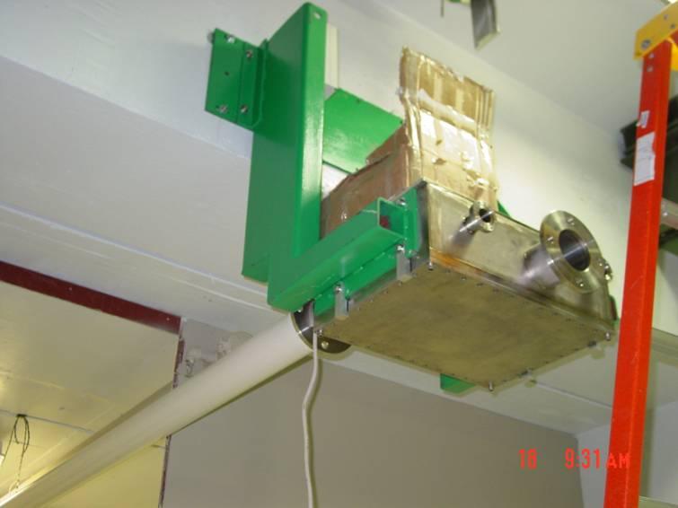
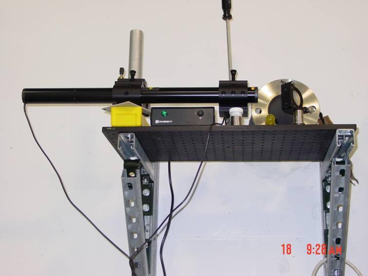
44 Laser Profile Monitor Progress Verification of electron collector for SCL laser profile monitor Reliable measurements to about 3 sigma Anti-reflection coating has been applied to the final windows. We expect an order of magnitude improvement in signal to noise ratio. Horizontal Profile Gaussian fit plotted out to 2.5x Sigma Sigma = 1.07 mm Signal from electron collector Top: laser intercepting beam core Bottom: laser intercepting beam tail
45 BNL: The Accumulator Ring and Transfer Lines Nr of injected turns 1060 Ring revolution frequency MHz Ring filling fraction % 68 Ring transverse emittance 99% πmm mrad 240 Ring transverse acceptance πmm mrad 480 Space charge Tune shift Q x,y 0.15 Peak Current 52 A HEBT / RTBT Length m 170 / 150 Ring Circumference m 248 RTBT transverse acceptance πmm mrad 480 Beam size on target (HxV) mm x mm 200x70 Totals: 235 Low Power Bipolar Supplies (< 5 kw) 24 Medium Power Bipolar Supplies (5-50 kw) 101 Medium Power Supplies (5-50 kw) 42 High Power Supplies (>50 kw) 22 Kicker Power Supplies Baseline: 1.0 GeV, 2 MW Designed and built for 1.3 GeV Several commissioning beam dumps

 to allow a 25 A")
46 BNL: Ring/HEBT Installation Progress Beam line installation Linac to Ring complete. Ring installation ~ 80% complete. Beam line installation Ring to Target has not started. The ring has an aperture of 460 π*mm*mrad (~ 15 cm diameter) to allow a 25 A average circulating current. From Chaos. Energy per pulse is ~ 25 kj.. To order!

47 RTBT/Target Interface 15 6 Target Flightube Q29 Harp Q30 Section through RTBT/Target Flight-tube Interface

48 Expected Dose Rates Q26 Q27 & Q28 Q29 & Q30 HARP Potential Active Maintenance Work Areas Prompt dose levels during operation (2 MW) 1500 working area (Franz Gallmeier) Residual levels 2 hours 1 week after shutdown, factor of ~1000 less 1.5 rem/hr Updated dose rate calculations underway with existing design (Irina Popova) Recent calculated dose rates for dumps & back streaming from target (DH13) are very high


49 September 02 People Instrument floor layout Status as of July 2004 with construction activity limited to Target & can be seen and target Status as of September 03 Central Laboratory building and Nano Science Center installation began


50 Target Monolith Region Monolith Installation - Sept 2003 Core Vessel and Shielding
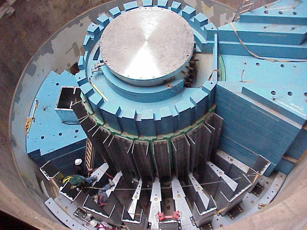
51 Target Installation


52 The SNS Target: 2-MW Design Cavitation-induced pitting is an issue. Options for mitigation: Materials, Geometry Mitigation 25 kj/pulse at 7x15cm beam size sets of transverse and longitudinal shock wave. Peanuts compared the Muon target! Needs to be exchanged every 3 month 1 mm Pits on inner surface in this geometry
53 Primary Concern: Uncontrolled Beam Loss Hands-on maintenance: no more than 100 mrem/hour residual activation (4 h cool down, 30 cm from surface) 1 Watt/m uncontrolled beam loss for linac & ring Less than 10-6 fractional beam loss per tunnel meter at 1 GeV; 10-4 loss for ring Uncontrolled loss during normal operation High rad areas Beam loss [W/m] FE DTL CCL SCL HEBT RING RTBT Length [m]
![A 20-Year Plan- The Long Term Future for SNS Doubling the number of Kinetic energy, E users by k [MeV] adding a 2 nd Beam power on target, P target station max [MW] Baseline Upgrade Ultimate 1000](/docs-images/77/76160348/images/54-1.jpg "1300 1400 1.4 3.0 5.0 Chopper beam-on duty factor [%] 68 70 70 Linac beam macro pulse duty factor [%] 6.0 6.")
54 A 20-Year Plan- The Long Term Future for SNS Doubling the number of Kinetic energy, E users by k [MeV] adding a 2 nd Beam power on target, P target station max [MW] Baseline Upgrade Ultimate Chopper beam-on duty factor [%] Linac beam macro pulse duty factor [%] Average Requires macropulse Energy H- current [ma] Peak upgrade Current from in front the end linac system Linac (ring average is beam already current ok [ma] for SRF cryo-module GeV) number (med-beta) SRF cryo-module number (high-beta) (+1 reserve) (+1 reserve) Number of SRF cavities (+4 reserve) (+4 reserve) Peak gradient, E p (β=0.61 cavity) [MV/m] 27.5 (+/- 2.5) 27.5 (+/- 2.5) 27.5 (+/- 2.5) Peak gradient, E p (β=0.81 cavity) [MV/m] 35 (+2.5/-7.5) Ring injection time [ms] / turns 1.0 / / / 1110 Ring rf frequency [MHz] Ring bunch intensity [10 14 ] Ring space-charge tune spread, Q sc Pulse length on target [ns]
55 P. Lapostolle,
56 Summary The SNS project is still on track for achieving a June 06 finish date within the appropriated 1.4 Billion $. The construction is more than 85% complete. The program has benefited from enormous support in Washington with funding appropriated every year as planned. Commissioning has progressed as installation continues with 40MeV achieved at full spec. The next major step is the commissioning of complete warm linac (DTL + CCL). The full linac should be in commissioning next spring during PAC 05. It has been and still is a very successful collaboration between six partnering DOE laboratories. Please come visit us next year during PAC or whenever you get a chance.

57 PAC05 PAC 05 will be in Knoxville, TN, 25 miles from the site. There will be a site tour on Saturday Please come to visit us..
Oak Ridge Spallation Neutron Source Proton Power Upgrade Project and Second Target Station Project
 Oak Ridge Spallation Neutron Source Proton Power Upgrade Project and Second Target Station Project Workshop on the future and next generation capabilities of accelerator driven neutron and muon sources
The Spallation Neutron Source Project Geneva December 8, 2006
 The Spallation Neutron Source Project Geneva December 8, 2006 Norbert Holtkamp ITER International Organization 13108 St Paul lez Durance Norbert.Holtkamp@iter.org The Spallation Neutron Source SNS is funded
Linac 4 Instrumentation K.Hanke CERN
 Linac 4 Instrumentation K.Hanke CERN CERN Linac 4 PS2 (2016?) SPL (2015?) Linac4 (2012) Linac4 will first inject into the PSB and then can be the first element of a new LHC injector chain. It will increase
SNS Target Imaging and Related Developments
 SNS Target Imaging and Related Developments Tom Shea (ORNL) ESS Seminar Lund, Sweden January 28, 2011 T. J. Shea, T. McManamy, G. Bancke, W. Blokland, A. Brunson, M. Dayton, R. Fiorito, K. C. Goetz, J.
The ESS Accelerator. For Norwegian Industry and Research. Oslo, 24 Sept Håkan Danared Deputy Head Accelerator Division Group Leader Beam Physics
 The ESS Accelerator For Norwegian Industry and Research Oslo, 24 Sept 2013 Håkan Danared Deputy Head Accelerator Division Group Leader Beam Physics The Hadron Intensity Frontier Courtesy of M. Seidel (PSI)
A Fifteen Year Perspective on the Design and Performance of the SNS Accelerator
 A Fifteen Year Perspective on the Design and Performance of the SNS Accelerator S. Cousineau (On behalf of the SNS project) HB2016, Sweden July 04, 2016 ORNL is managed by UT-Battelle for the US Department
Commissioning of Accelerators. Dr. Marc Munoz (with the help of R. Miyamoto, C. Plostinar and M. Eshraqi)
") Commissioning of Accelerators Dr. Marc Munoz (with the help of R. Miyamoto, C. Plostinar and M. Eshraqi) www.europeanspallationsource.se 6 July, 2017 Contents General points Definition of Commissioning
Commissioning of Accelerators Dr. Marc Munoz (with the help of R. Miyamoto, C. Plostinar and M. Eshraqi) www.europeanspallationsource.se 6 July, 2017 Contents General points Definition of Commissioning
Workshop on Accelerator Operations August 6-10, 2012 Glen D. Johns Accelerator Operations Manager
 HWDB: Operations at the Spallation Neutron Source Workshop on Accelerator Operations August 6-10, 2012 Glen D. Johns Accelerator Operations Manager Outline Facility overview Organization Shift schedule
Beam Loss Detection for MPS at FRIB
 Beam Loss Detection for MPS at FRIB Zhengzheng Liu Beam Diagnostics Physicist This material is based upon work supported by the U.S. Department of Energy Office of Science under Cooperative Agreement DE-SC0000661.
The PEFP 20-MeV Proton Linear Accelerator
 Journal of the Korean Physical Society, Vol. 52, No. 3, March 2008, pp. 721726 Review Articles The PEFP 20-MeV Proton Linear Accelerator Y. S. Cho, H. J. Kwon, J. H. Jang, H. S. Kim, K. T. Seol, D. I.
Diamond RF Status (RF Activities at Daresbury) Mike Dykes
 Mike Dykes") Diamond RF Status (RF Activities at Daresbury) Mike Dykes ASTeC What is it? What does it do? Diamond Status Linac Booster RF Storage Ring RF Summary Content ASTeC ASTeC was formed in 2001 as a centre of
Diamond RF Status (RF Activities at Daresbury) Mike Dykes ASTeC What is it? What does it do? Diamond Status Linac Booster RF Storage Ring RF Summary Content ASTeC ASTeC was formed in 2001 as a centre of
Upgrading LHC Luminosity
 1 Upgrading LHC Luminosity 2 Luminosity (cm -2 s -1 ) Present (2011) ~2 x10 33 Beam intensity @ injection (*) Nominal (2015?) 1 x 10 34 1.1 x10 11 Upgraded (2021?) ~5 x10 34 ~2.4 x10 11 (*) protons per
The Construction Status of CSNS Linac
 The Construction Status of CSNS Linac Sheng Wang Dongguan branch, Institute of High Energy Physics, CAS Sep.2, 2014, Geneva Outline The introduction to CSNS accelerators The commissoning of ion source
Experience with the Cornell ERL Injector SRF Cryomodule during High Beam Current Operation
 Experience with the Cornell ERL Injector SRF Cryomodule during High Beam Current Operation Matthias Liepe Assistant Professor of Physics Cornell University Experience with the Cornell ERL Injector SRF
Proton Engineering Frontier Project
 Proton Engineering Frontier Project OECD Nuclear Energy Agency Fifth International Workshop on the Utilisation and Reliability of High Power Proton Accelerators (HPPA5) (6-9 May 2007, Mol, Belgium) Yong-Sub
Detailed Design Report
 Detailed Design Report Chapter 4 MAX IV Injector 4.6. Acceleration MAX IV Facility CHAPTER 4.6. ACCELERATION 1(10) 4.6. Acceleration 4.6. Acceleration...2 4.6.1. RF Units... 2 4.6.2. Accelerator Units...
DESIGN OF 1.2-GEV SCL AS NEW INJECTOR FOR THE BNL AGS*
 DESIGN OF 1.2-GEV SCL AS NEW INJECTOR FOR THE BNL AGS* A. G. Ruggiero, J. Alessi, M. Harrison, M. Iarocci, T. Nehring, D. Raparia, T. Roser, J. Tuozzolo, W. Weng. Brookhaven National Laboratory, PO Box
RF plans for ESS. Morten Jensen. ESLS-RF 2013 Berlin
 RF plans for ESS Morten Jensen ESLS-RF 2013 Berlin Overview The European Spallation Source (ESS) will house the most powerful proton linac ever built. The average beam power will be 5 MW which is five
L-Band RF R&D. SLAC DOE Review June 15 th, Chris Adolphsen SLAC
 L-Band RF R&D SLAC DOE Review June 15 th, 2005 Chris Adolphsen SLAC International Linear Collider (ILC) RF Unit (TESLA TDR Layout) Gradient = 23.4 MV/m Bunch Spacing = 337 ns Fill Time = 420 µs Train Length
ESS: The Machine. Bucharest, 24 April Håkan Danared Deputy Head Accelerator Division. H. Danared Industry & Partner Days Bucharest Page 1
 ESS: The Machine Bucharest, 24 April 2014 Håkan Danared Deputy Head Accelerator Division H. Danared Industry & Partner Days Bucharest Page 1 2025 ESS construction complete 2009 Decision: ESS will be built
3 cerl. 3-1 cerl Overview. 3-2 High-brightness DC Photocathode Gun and Gun Test Beamline
 3 cerl 3-1 cerl Overview As described before, the aim of the cerl in the R&D program includes the development of critical components for the ERL, as well as the construction of a test accelerator. The
Upgrade of CEBAF to 12 GeV
 Upgrade of CEBAF to 12 GeV Leigh Harwood (for 12 GeV Accelerator team) Page 1 Outline Background High-level description Schedule Sub-system descriptions and status Summary Page 2 CEBAF Science Mission
OPERATIONAL EXPERIENCE AT J-PARC
 OPERATIONAL EXPERIENCE AT J-PARC Hideaki Hotchi, ) for J-PARC commissioning team ), 2), ) Japan Atomic Energy Agency (JAEA), Tokai, Naka, Ibaraki, 39-95 Japan, 2) High Energy Accelerator Research Organization
Preparations for Installation, Testing and Commissioning based on Experience at CERN, SNS and Siemens
 Preparations for Installation, Testing and Commissioning based on Experience at CERN, SNS and Siemens Eugène Tanke FRIB / MSU ESS Seminar, Lund, 6 March 2013 Outline Project Goal for the Accelerator Path
COMMISSIONING SCENARIOS FOR THE J-PARC ACCELERATOR COMPLEX
 COMMISSIONING SCENARIOS FOR THE J-PARC ACCELERATOR COMPLEX T. Koseki, M. Ikegami, M. Tomizawa, Accelerator Laboratory, KEK, Tsukuba, Japan F. Noda, JAEA, Tokai, Japan Abstract The J-PARC (Japan Proton
PRESENT STATUS OF J-PARC
 PRESENT STATUS OF J-PARC # F. Naito, KEK, Tsukuba, Japan Abstract Japan Proton Accelerator Research Complex (J-PARC) is the scientific facility with the high-intensity proton accelerator aiming to realize
High Brightness Injector Development and ERL Planning at Cornell. Charlie Sinclair Cornell University Laboratory for Elementary-Particle Physics
 High Brightness Injector Development and ERL Planning at Cornell Charlie Sinclair Cornell University Laboratory for Elementary-Particle Physics June 22, 2006 JLab CASA Seminar 2 Background During 2000-2001,
RF considerations for SwissFEL
 RF considerations for H. Fitze in behalf of the PSI RF group Workshop on Compact X-Ray Free Electron Lasers 19.-21. July 2010, Shanghai Agenda Introduction RF-Gun Development C-band development Summary
2 Work Package and Work Unit descriptions. 2.8 WP8: RF Systems (R. Ruber, Uppsala)
") 2 Work Package and Work Unit descriptions 2.8 WP8: RF Systems (R. Ruber, Uppsala) The RF systems work package (WP) addresses the design and development of the RF power generation, control and distribution
2 Work Package and Work Unit descriptions 2.8 WP8: RF Systems (R. Ruber, Uppsala) The RF systems work package (WP) addresses the design and development of the RF power generation, control and distribution
RF Upgrades & Experience At JLab. Rick Nelson
 RF Upgrades & Experience At JLab Rick Nelson Outline Background: CEBAF / Jefferson Lab History, upgrade requirements & decisions Progress & problems along the way Present status Future directions & concerns
A HIGH-POWER SUPERCONDUCTING H - LINAC (SPL) AT CERN
 AT CERN") A HIGH-POWER SUPERCONDUCTING H - LINAC (SPL) AT CERN E. Chiaveri, CERN, Geneva, Switzerland Abstract The conceptual design of a superconducting H - linear accelerator at CERN for a beam energy of 2.2 GeV
A HIGH-POWER SUPERCONDUCTING H - LINAC (SPL) AT CERN E. Chiaveri, CERN, Geneva, Switzerland Abstract The conceptual design of a superconducting H - linear accelerator at CERN for a beam energy of 2.2 GeV
4.4 Injector Linear Accelerator
 4.4 Injector Linear Accelerator 100 MeV S-band linear accelerator based on the components already built for the S-Band Linear Collider Test Facility at DESY [1, 2] will be used as an injector for the CANDLE
STATUS OF THE SWISSFEL C-BAND LINEAR ACCELERATOR
 Proceedings of FEL213, New York, NY, USA STATUS OF THE SWISSFEL C-BAND LINEAR ACCELERATOR F. Loehl, J. Alex, H. Blumer, M. Bopp, H. Braun, A. Citterio, U. Ellenberger, H. Fitze, H. Joehri, T. Kleeb, L.
5 Project Costs and Schedule
 93 5 Project Costs and Schedule 5.1 Overview The cost evaluation for the integrated version of the XFEL with 30 experiments and 35 GeV beam energy as described in the TDR-2001 yielded 673 million EUR for
HIGH-INTENSITY PROTON BEAMS AT CERN AND THE SPL STUDY
 HIGH-INTENSITY PROTON BEAMS AT CERN AND THE STUDY E. Métral, M. Benedikt, K. Cornelis, R. Garoby, K. Hanke, A. Lombardi, C. Rossi, F. Ruggiero, M. Vretenar, CERN, Geneva, Switzerland Abstract The construction
The Beam Test Facility at the SNS
 The Beam Test Facility at the SNS R.F. Welton, A. Aleksandrov, B.X. Han, Y.W. Kang, M.M. Middendorf, S.N. Murray, M. Piller, T.R. Pennisi, V. Peplov, R. Saethre, M. Santana, C. Stinson, M.P. Stockli and
Welcome and FRIB Project Status. FRIB Highlights and Plan Ahead
 Welcome and FRIB Project Status Thomas Glasmacher Project Manager This material is based upon work supported by the U.S. Department of Energy Office of Science under Cooperative Agreement DE-SC0000661.
Summary of the 1 st Beam Line Review Meeting Injector ( )
") Summary of the 1 st Beam Line Review Meeting Injector (23.10.2006) 15.11.2006 Review the status of: beam dynamics understanding and simulations completeness of beam line description conceptual design of
Summary of the 1 st Beam Line Review Meeting Injector (23.10.2006) 15.11.2006 Review the status of: beam dynamics understanding and simulations completeness of beam line description conceptual design of
HIGH POWER BEAM DUMP AND TARGET / ACCELERATOR INTERFACE PROCEDURES *
 HIGH POWER BEAM DUMP AND TARGET / ACCELERATOR INTERFACE PROCEDURES * J. Galambos, W. Blokland, D. Brown, C. Peters, M. Plum, Spallation Neutron Source, ORNL, Oak Ridge, TN 37831, U.S.A. Abstract Satisfying
INFN School on Electron Accelerators. RF Power Sources and Distribution
 INFN School on Electron Accelerators 12-14 September 2007, INFN Sezione di Pisa Lecture 7b RF Power Sources and Distribution Carlo Pagani University of Milano INFN Milano-LASA & GDE The ILC Double Tunnel
The LEP Superconducting RF System
 The LEP Superconducting RF System K. Hübner* for the LEP RF Group CERN The basic components and the layout of the LEP rf system for the year 2000 are presented. The superconducting system consisted of
Current status of XFEL/SPring-8 project and SCSS test accelerator
 Current status of XFEL/SPring-8 project and SCSS test accelerator Takahiro Inagaki for XFEL project in SPring-8 inagaki@spring8.or.jp Outline (1) Introduction (2) Key technology for compactness (3) Key
SUMMARY OF THE ILC R&D AND DESIGN
 SUMMARY OF THE ILC R&D AND DESIGN B. C. Barish, California Institute of Technology, USA Abstract The International Linear Collider (ILC) is a linear electron-positron collider based on 1.3 GHz superconducting
P. Emma, et al. LCLS Operations Lectures
 P. Emma, et al. LCLS Operations Lectures LCLS 1 LCLS Accelerator Schematic 6 MeV 135 MeV 250 MeV σ z 0.83 mm σ z 0.83 mm σ z 0.19 mm σ δ 0.05 % σ δ 0.10 % σ δ 1.6 % Linac-0 L =6 m rf gun L0-a,b Linac-1
PEP II Design Outline
 PEP II Design Outline Balša Terzić Jefferson Lab Collider Review Retreat, February 24, 2010 Outline General Information Parameter list (and evolution), initial design, upgrades Collider Ring Layout, insertions,
LSD Review December 2012 Schedule, Re-Baseline, & Resource Analysis
 LSD Review December 2012 Schedule, Re-Baseline, & Resource Analysis Dianne Napier Outline Part II Review Charges Addressed in this Presentation: Issues raised in Part I Review Report adequately addressed
Jefferson Lab Experience with Beam Halo, Beam Loss, etc.
 Jefferson Lab Experience with Beam Halo, Beam Loss, etc. Pavel Evtushenko with a lot of input from many experienced colleagues Steve Benson, Dave Douglas, Kevin Jordan, Carlos Hernandez-Garcia, Dan Sexton,
The SPL at CERN. slhc. 1. Introduction 2. Description. 3. Status of the SPL study. - Stage 1: Linac4 - Stage 2: LP-SPL - Potential further stages
 The SPL at CERN 1. Introduction 2. Description - Stage 1: Linac4 - Stage 2: LP-SPL - Potential further stages 3. Status of the SPL study slhc Roa Garoby for the SPL team 1. Introduction Motivation for
EPJ Web of Conferences 95,
 EPJ Web of Conferences 95, 04012 (2015) DOI: 10.1051/ epjconf/ 20159504012 C Owned by the authors, published by EDP Sciences, 2015 The ELENA (Extra Low Energy Antiproton) project is a small size (30.4
Status of SOLARIS Arkadiusz Kisiel
 Status of SOLARIS Arkadiusz Kisiel Solaris National Synchrotron Light Source Jagiellonian University Czerwone Maki 98 30-392 Kraków www.synchrotron.uj.edu.pl Arkadiusz.Kisiel@uj.edu.pl On behalf of SOLARIS
CEBAF Accelerator Update. Michael Tiefenback CASA Accelerator Physics Experimental Liaison June 14, 2017
 CEBAF Accelerator Update Michael Tiefenback CASA Accelerator Physics Experimental Liaison June 14, 2017 CLAS12 Collaboration Meeting, June 13-16, 2017 1 Accelerator Division Leadership On April 30 Andrew
Present Status and Future Upgrade of KEKB Injector Linac
 Present Status and Future Upgrade of KEKB Injector Linac Kazuro Furukawa, for e /e + Linac Group Present Status Upgrade in the Near Future R&D towards SuperKEKB 1 Machine Features Present Status and Future
Status of RF Power and Acceleration of the MAX IV - LINAC
 Status of RF Power and Acceleration of the MAX IV - LINAC Dionis Kumbaro ESLS RF Workshop 2015 MAX IV Laboratory A National Laboratory for synchrotron radiation at Lunds University 1981 MAX-lab is formed
30 GHz Power Production / Beam Line
 30 GHz Power Production / Beam Line Motivation & Requirements Layout Power mode operation vs. nominal parameters Beam optics Achieved performance Problems Beam phase switch for 30 GHz pulse compression
A New High Intensity Proton Source. The SCRF Proton Driver. (and more!) at Fermilab. July 15, Bill Foster SRF2005
 at Fermilab. July 15, Bill Foster SRF2005") The SCRF Proton Driver A New High Intensity Proton Source (and more!) at Fermilab Bill Foster SRF2005 July 15, 2005 Outline The Concept Fermilab Strategic Context Proton Driver SRF Linac Design Ferrite
The SCRF Proton Driver A New High Intensity Proton Source (and more!) at Fermilab Bill Foster SRF2005 July 15, 2005 Outline The Concept Fermilab Strategic Context Proton Driver SRF Linac Design Ferrite
LHC Beam Instrumentation Further Discussion
 LHC Beam Instrumentation Further Discussion LHC Machine Advisory Committee 9 th December 2005 Rhodri Jones (CERN AB/BDI) Possible Discussion Topics Open Questions Tune measurement base band tune & 50Hz
IOT OPERATIONAL EXPERIENCE ON ALICE AND EMMA AT DARESBURY LABORATORY
 IOT OPERATIONAL EXPERIENCE ON ALICE AND EMMA AT DARESBURY LABORATORY A. Wheelhouse ASTeC, STFC Daresbury Laboratory ESLS XVIII Workshop, ELLETRA 25 th 26 th November 2010 Contents Brief Description ALICE
SPEAR 3: Operations Update and Impact of Top-Off Injection
 SPEAR 3: Operations Update and Impact of Top-Off Injection R. Hettel for the SSRL ASD 2005 SSRL Users Meeting October 18, 2005 SPEAR 3 Operations Update and Development Plans Highlights of 2005 SPEAR 3
XFEL High Power RF System Recent Developments
 XFEL High Power RF System Recent Developments for the XFEL RF Group Outline XFEL RF System Requirements Overview Basic Layout RF System Main Components Multibeam Klystrons Modulator RF Waveguide Distribution
RUNNING EXPERIENCE OF FZD SRF PHOTOINJECTOR
 RUNNING EXPERIENCE OF FZD SRF PHOTOINJECTOR Rong Xiang On behalf of the BESSY-DESY-FZD-MBI collaboration and the ELBE team FEL 2009, Liverpool, United Kingdom, August 23 ~ 28, 2009 Outline Introduction
DELIVERY RECORD. Location: Ibaraki, Japan
 DELIVERY RECORD Client: Japan Atomic Energy Agency (JAEA) High Energy Accelerator Research Organization (KEK) Facility: J-PARC (Japan Proton Accelerator Research Complex) Location: Ibaraki, Japan 1 October
Status of BESSY II and berlinpro. Wolfgang Anders. Helmholtz-Zentrum Berlin for Materials and Energy (HZB) 20th ESLS-RF Meeting
 20th ESLS-RF Meeting") Status of BESSY II and berlinpro Wolfgang Anders Helmholtz-Zentrum Berlin for Materials and Energy (HZB) 20th ESLS-RF Meeting 16.-17.11.2016 at PSI Outline BESSY II Problems with circulators Landau cavity
Status of BESSY II and berlinpro Wolfgang Anders Helmholtz-Zentrum Berlin for Materials and Energy (HZB) 20th ESLS-RF Meeting 16.-17.11.2016 at PSI Outline BESSY II Problems with circulators Landau cavity
Activities on FEL Development and Application at Kyoto University
 Activities on FEL Development and Application at Kyoto University China-Korea-Japan Joint Workshop on Electron / Photon Sources and Applications Dec. 2-3, 2010 @ SINAP, Shanghai Kai Masuda Inst. Advanced
Pulsed Klystrons for Next Generation Neutron Sources Edward L. Eisen - CPI, Inc. Palo Alto, CA, USA
 Pulsed Klystrons for Next Generation Neutron Sources Edward L. Eisen - CPI, Inc. Palo Alto, CA, USA Abstract The U.S. Department of Energy (DOE) Office of Science has funded the construction of a new accelerator-based
Status of the FAIR Project. Jürgen Henschel FAIR Project Leader / Technical Director GSI & FAIR
 Status of the FAIR Project Jürgen Henschel FAIR Project Leader / Technical Director GSI & FAIR Finland France Germany India Poland Romania Russia Slovenia Sweden UK FAIR Strategic objectives FAIR phase
SNS TR0001-R00. Conceptual Design Report for the Spallation Neutron Source Power Upgrade MIE Project
 SNS-300000000-TR0001-R00 Conceptual Design Report for the Spallation Neutron Source Power Upgrade MIE Project This report was prepared as an account of work sponsored by an agency of the United States
!"!3
 Abstract A single-mode 500 MHz superconducting cavity cryomodule has been developed at Cornell for the electronpositron collider/synchrotron light source CESR. The Cornell B-cell cavity belongs to the
Commissioning the TAMUTRAP RFQ cooler/buncher. E. Bennett, R. Burch, B. Fenker, M. Mehlman, D. Melconian, and P.D. Shidling
 Commissioning the TAMUTRAP RFQ cooler/buncher E. Bennett, R. Burch, B. Fenker, M. Mehlman, D. Melconian, and P.D. Shidling In order to efficiently load ions into a Penning trap, the ion beam should be
High Rep Rate Guns: FZD Superconducting RF Photogun
 High Rep Rate Guns: FZD Superconducting RF Photogun J. Teichert, A. Arnold, H. Büttig, D. Janssen, M. Justus, U. Lehnert, P. Michel, K. Moeller, P. Murcek, Ch. Schneider, R. Schurig, G. Staats, F. Staufenbiel,
ESS Linac WP8 Radio Frequency Systems and Test Facilities
 ESS Linac WP8 Radio Frequency Systems and Test Facilities ESS/SPL Collaboration Meeting Lund, 29 June 2010 Roger Ruber (Uppsala University) for the ESS Linac RF Team ESS Linac WP8: RF Systems Outline Work
Next Linear Collider. The 8-Pack Project. 8-Pack Project. Four 50 MW XL4 X-band klystrons installed on the 8-Pack
 The Four 50 MW XL4 X-band klystrons installed on the 8-Pack The Demonstrate an NLC power source Two Phases: 8-Pack Phase-1 (current): Multi-moded SLED II power compression Produce NLC baseline power: 475
Digital BPMs and Orbit Feedback Systems
 Digital BPMs and Orbit Feedback Systems, M. Böge, M. Dehler, B. Keil, P. Pollet, V. Schlott Outline stability requirements at SLS storage ring digital beam position monitors (DBPM) SLS global fast orbit
Photoinjector Laser Operation and Cathode Performance
 Photoinjector Laser Operation and Cathode Performance Daniele Sertore, INFN Milano LASA Siegfried Schreiber, DESY Laser operational experience Laser beam properties Cathode performances Outlook TTF and
A HIGH POWER LONG PULSE HIGH EFFICIENCY MULTI BEAM KLYSTRON
 A HIGH POWER LONG PULSE HIGH EFFICIENCY MULTI BEAM KLYSTRON A.Beunas and G. Faillon Thales Electron Devices, Vélizy, France S. Choroba DESY, Hamburg, Germany Abstract THALES ELECTRON DEVICES has developed
The Elettra Storage Ring and Top-Up Operation
 The Elettra Storage Ring and Top-Up Operation Emanuel Karantzoulis Past and Present Configurations 1994-2007 From 2008 5000 hours /year to the users 2010: Operations transition year Decay mode, 2 GeV (340mA)
THE OPERATION EXPERIENCE AT KOMAC*
 THAM2X01 Proceedings of HB2016, Malmö, Sweden THE OPERATION EXPERIENCE AT KOMAC* Yong-Sub Cho, Kye-Ryung Kim, Kui Young Kim, Hyeok-Jung Kwon, Han-Sung Kim, Young-Gi Song Korea Atomic Energy Research Institute,
Basic rules for the design of RF Controls in High Intensity Proton Linacs. Particularities of proton linacs wrt electron linacs
 Basic rules Basic rules for the design of RF Controls in High Intensity Proton Linacs Particularities of proton linacs wrt electron linacs Non-zero synchronous phase needs reactive beam-loading compensation
Design of the linear accelerator for the MYRRHA project
 MYRRHA Multipurpose hybrid Research Reactor for High-tech Applications Design of the linear accelerator for the MYRRHA project Roberto Salemme ADT - Outline What is MYRRHA? MYRRHA accelerator: requirements
The European Spallation Source
 The European Spallation Source Roger Ruber Uppsala University NIKHEF industriemiddag 21 september 2011 The European Spallation Source Roger Ruber - The European Spallation Source NIKHEF, 21-Sep-2011 page
PoS(EPS-HEP2015)525. The RF system for FCC-ee. A. Butterworth CERN 1211 Geneva 23, Switzerland
525. The RF system for FCC-ee. A. Butterworth CERN 1211 Geneva 23, Switzerland") CERN 1211 Geneva 23, Switzerland E-mail: andrew.butterworth@cern.ch O. Brunner CERN 1211 Geneva 23, Switzerland E-mail: olivier.brunner@cern.ch R. Calaga CERN 1211 Geneva 23, Switzerland E-mail: rama.calaga@cern.ch
CERN 1211 Geneva 23, Switzerland E-mail: andrew.butterworth@cern.ch O. Brunner CERN 1211 Geneva 23, Switzerland E-mail: olivier.brunner@cern.ch R. Calaga CERN 1211 Geneva 23, Switzerland E-mail: rama.calaga@cern.ch
NSLS-II RF Systems James Rose, Radio Frequency Group Leader PAC 2011
 NSLS-II RF Systems James Rose, Radio Frequency Group Leader PAC 2011 1 BROOKHAVEN SCIENCE ASSOCIATES Introduction Linac RF cavities and klystrons Booster Cavity-Transmitter Storage Ring 500 MHz SRF cavity
Status of CTF3. G.Geschonke CERN, AB
 Status of CTF3 G.Geschonke CERN, AB CTF3 layout CTF3 - Test of Drive Beam Generation, Acceleration & RF Multiplication by a factor 10 Drive Beam Injector ~ 50 m 3.5 A - 2100 b of 2.33 nc 150 MeV - 1.4
Operating Experience and Reliability Improvements on the 5 kw CW Klystron at Jefferson Lab
 Operating Experience and Reliability Improvements on the 5 kw CW Klystron at Jefferson Lab Richard Walker & Richard Nelson Jefferson Lab, Newport News VA Jefferson Lab is a $600M Department of Energy facility
Beam Losses During LCLS Injector Phase-1 1 Operation
 Beam Losses During LCLS Injector Phase-1 1 Operation & Paul Emma September 28, 2006 Radiation Safety Committee Review Scope of Phase 1 Operation Request for Three Operating Modes Operating Plan for Phase
Design Studies For The LCLS 120 Hz RF Gun Injector
 BNL-67922 Informal Report LCLS-TN-01-3 Design Studies For The LCLS 120 Hz RF Gun Injector X.J. Wang, M. Babzien, I. Ben-Zvi, X.Y. Chang, S. Pjerov, and M. Woodle National Synchrotron Light Source Brookhaven
Performance of a DC GaAs photocathode gun for the Jefferson lab FEL
 Nuclear Instruments and Methods in Physics Research A 475 (2001) 549 553 Performance of a DC GaAs photocathode gun for the Jefferson lab FEL T. Siggins a, *, C. Sinclair a, C. Bohn b, D. Bullard a, D.
WG2 Group Summary. Chris Adolphsen Terry Garvey Hitoshi Hayano
 WG2 Group Summary Chris Adolphsen Terry Garvey Hitoshi Hayano Linac Options Fest On Thursday afternoon, various experts summarized the linac baseline options. Although hard choices have yet to be made,
Photo cathode RF gun -
 Photo cathode RF gun - *),,, ( 05 Nov. 2004 Spring8 UTNL Linac & Mg Photocathode RF Gun Mg photocathode NERL, 18 MeV Linac and the RF gun Electron Beam Mg photocathode Mg photocathode RF gun of SPring8
Introduction: CW SRF linac types, requirements and challenges High power RF system architecture
 RF systems for CW SRF linacs S. Belomestnykh Cornell University Laboratory for Elementary-Particle Physics LINAC08, Victoria, Canada October 1, 2008 Outline L band Introduction: CW SRF linac types, requirements
Particle Beam Production - A Synchrotron-Based System - Prof. Dr. Thomas Haberer Scientific-technical Director Heidelberg Iontherapy Center
 Particle Beam Production - A Synchrotron-Based System - Prof. Dr. Thomas Haberer Scientific-technical Director Heidelberg Iontherapy Center Outline Situation/Rationale Requirements Synchrotron choice Functions
RF Power Klystrons & 20 Year Look. R. Nelson 7/15/15
 RF Power Klystrons & 20 Year Look R. Nelson 7/15/15 RF Power klystrons 8 x 13 kw klystrons Page 2 Why A klystron? Best (only) choice at the time - 1988 Easy to use: Input (drive), output (to CM), power
Towards an X-Band Power Source at CERN and a European Structure Test Facility
 Towards an X-Band Power Source at CERN and a European Structure Test Facility Erk Jensen and Gerry McMomagle CERN The X-Band Accelerating Structure Design and Test-Program Workshop Day 2: Structure Testing
CERN S PROTON SYNCHROTRON COMPLEX OPERATION TEAMS AND DIAGNOSTICS APPLICATIONS
 Marc Delrieux, CERN, BE/OP/PS CERN S PROTON SYNCHROTRON COMPLEX OPERATION TEAMS AND DIAGNOSTICS APPLICATIONS CERN s Proton Synchrotron (PS) complex How are we involved? Review of some diagnostics applications
KEKB INJECTOR LINAC AND UPGRADE FOR SUPERKEKB
 KEKB INJECTOR LINAC AND UPGRADE FOR SUPERKEKB S. Michizono for the KEK electron/positron Injector Linac and the Linac Commissioning Group KEK KEKB injector linac Brief history of the KEK electron linac
ESS Linac WP8 Radio Frequency Systems and Test Facilities
 ESS Linac WP8 Radio Frequency Systems and Test Facilities ESS TAC Lund, 8 July 2010 Roger Ruber (Uppsala University) for the ESS Linac RF Team Outline Work Package description Objectives Organization Technical
Evaluation of Performance, Reliability, and Risk for High Peak Power RF Sources from S-band through X-band for Advanced Accelerator Applications
 Evaluation of Performance, Reliability, and Risk for High Peak Power RF Sources from S-band through X-band for Advanced Accelerator Applications Michael V. Fazio C. Adolphsen, A. Jensen, C. Pearson, D.
Status of SOLARIS. Paweł Borowiec On behalf of Solaris Team
 Status of SOLARIS Paweł Borowiec On behalf of Solaris Team e-mail: pawel.borowiec@uj.edu.pl XX ESLS-RF Meeting, Villingen 16-17.11.2016 Outline 1. Timeline 2. Injector 3. Storage ring 16-17.11.2016 XX
DEVELOPMENT OF A 10 MW SHEET BEAM KLYSTRON FOR THE ILC*
 DEVELOPMENT OF A 10 MW SHEET BEAM KLYSTRON FOR THE ILC* D. Sprehn, E. Jongewaard, A. Haase, A. Jensen, D. Martin, SLAC National Accelerator Laboratory, Menlo Park, CA 94020, U.S.A. A. Burke, SAIC, San
Low Level RF for PIP-II. Jonathan Edelen LLRF 2017 Workshop (Barcelona) 16 Oct 2017
 16 Oct 2017") Low Level RF for PIP-II Jonathan Edelen LLRF 2017 Workshop (Barcelona) 16 Oct 2017 PIP-II LLRF Team Fermilab Brian Chase, Edward Cullerton, Joshua Einstein, Jeremiah Holzbauer, Dan Klepec, Yuriy Pischalnikov,
Low Level RF for PIP-II Jonathan Edelen LLRF 2017 Workshop (Barcelona) 16 Oct 2017 PIP-II LLRF Team Fermilab Brian Chase, Edward Cullerton, Joshua Einstein, Jeremiah Holzbauer, Dan Klepec, Yuriy Pischalnikov,
News from HZB / BESSY Wolfgang Anders at ESLS-RF Meeting September 2010 Trieste
 News from HZB / BESSY Wolfgang Anders at ESLS-RF Meeting September 2010 Trieste Outline Status Klystrons / IOT Modifications of transmitters New LINAC for BESSY II Status BERLinPro HoBiCaT Extension --