// K4815 // Pattern Generator. User Manual. Hardware Version D-F Firmware Version 1.2x February 5, 2013 Kilpatrick Audio
|
|
|
- Darren Mitchell
- 6 years ago
- Views:
Transcription

1 // K4815 // Pattern Generator Kilpatrick Audio
2 // K4815 // Pattern Generator 2p Introduction Welcome to the wonderful world of the K4815 Pattern Generator. The K4815 is a unique and flexible way of generating notes, rhythms and modulation voltages or control changes. The user interacts with the machine to set the patterns using an unconventional method which works well to find new grooves and musical inspiration. It is a perfect performance tool, a source of notes for jamming, or a way to creating voltages synchronized to a common clock. This manual will explain the features and operation of the unit. Please check for updates to the documentation and firmware often as new features may be added at users' request. We continually strive to advance our products for your benefit and enjoyment. Features Eurorack form factor with 20HP width Musical note, control and clock signals generated using unique methods 64 LED (8x8) multi-brightness grid to show patterns and status Clock control via internal clock, or external MIDI or analog clock Clock, Direction and Reset inputs (0V / 5V = off / on) CV/GATE or /Y analog outputs (-5V to +5V range) CV is 1V/octave 10 octave range GATE is 0V or 5V /Y outputs are -2.5V to +2.5V (can be shifted beyond this range) Internal MIDI header compatible with other Kilpatrick Audio MIDI modules MIDI implementation with send/receive capability for full MIDI integration nly 30mm deep (including ribbon cables) Requires +12V (80mA) and -12V (less than 10mA) 16 pin Doepfer-style power connection required (included)
3 // K4815 // Pattern Generator 3p Installation and Setup When installing the K4815 in your modular system, pay close attention to the pinout and direction of the 16-pin power input cable. The K4815 contains protection against reverse connection, but please double-check the cable before switching on the unit. The warranty does not cover damage caused by wrong installation. Note: riginal K4815 modules required +5V in addition to +/-12V. Serial numbers and higher only require +/-12V. If you have an older model and wish to have it upgrade free of charge, (parts and labour only) please contact Kilpatrick Audio directly for more information. The K4815 Pattern Generator supports both MIDI and control voltage/gate/clock signals. To use the MIDI function requires the use of a MIDI adaptor such as the K1600 MIDI Converter. But the K4815 can be used by itself without any MIDI devices by using the analog inputs and outputs. If you are using the module with another MIDI device using the internal MIDI cable, connect a 10 pin ribbon cable between the two units. In this case also observe the correct cable direction. Warning: D NT plug the MIDI cable into the power port, or vice versa.
4
5 // K4815 // Pattern Generator 5p Choose a motion type by turning the MTIN TYPE knob. This selects the motion of the playback ball. Turn up the MTIN LENGTH knob to maximum to play every step in the motion sequence. Adjust the pattern type with the PATTERN TYPE knob to select where notes will play. You should hear notes being generated as the playback ball lands on active notes on the grid. Using the MAJ / MIN and LARGE / SMALL switches, you can choose from major or minor tonalities, as well as large and small output spans. The GATE TIME knob affects how long each note plays, and the MTIN LENGTH knob affects how many of the up to 64 steps in each motion sequence will play before repeating. Play around with the controls and hear some of the different possibilities. The next section will cover each control in more detail, as well as a more overall discussion of how the K4815 makes patterns based on the settings that you have selected.
6
7 // K4815 // Pattern Generator 7p Advanced peration Internal Clocking and Timing Using External Clock The machine uses a 24ppq internal timebase. The clock can be supplied by MIDI timing ticks, by an analog (+5V or greater) clock input signal, or by the internal clock generator. The analog clock triggers on the rising edge and can support clock rates up to approx. 100pps. (250bpm) Each clock pulse input accounts for 1/24th of a beat. When using external clock mode you can adjust how many clock pulses are required to advance the pattern one step. These are set by the CLCK SPEED pot and range from 1-24 pulses per step. The supported divisions allow: 1, 2, 3, 4, 6, 8, 12 or 24 notes per beat. (24 ticks) The division is only changed at the end of a beat (24 internal counts] to prevent jumpy behaviour. The clock divider setting will be briefly shown on the display when the CLCK SPEED control is adjusted. When external clocks are input either by MIDI or by the analog clock input, MIDI clock pulses are transmitted on the internal MIDI header. In this way you can convert analog clock signals to MIDI signals. Note: Using MIDI and analog clock at the same time may produce undesired results. To prevent stuck notes in the case of external clock loss, playing notes are automatically killed if no clock signals are received for 5 seconds. This means that extremely slow tempos of less than 0.5bpm are not supported. (You might require caffeine if this is the tempo of your piece!) Using Internal Clock When using the internal clock mode, the CLCK SPEED pot sets the tempo. In this mode the pattern always advances four steps per beat. (16th notes) The tempo generated by the internal clock can range from approx. 19 to 400bpm. When using the internal clock mode, MIDI clock is automatically transmitted. If the CLCK SPEED pot is turned all the way down the clock will be stopped. Clock LED The clock LED will pulse for a short time at the beginning of every beat. (every 24 clock ticks) GATE TIME Control When notes are played, the GATE TIME control affects how long the notes will play. When in the minimum setting, the note will play for 1 internal clock tick. At the maximum setting, the note can play for more than two full beats. Note that this control scales automatically with the tempo. Some synthesizer patches might be barely audible if the gate time is short and the tempo is high.
8 // K4815 // Pattern Generator 8p FWD/REV Control and DIR Input While any motion is playing, the direction can be reversed by adjusting the FWD/REV switch. It can also be reversed by an external voltage. If +5V or greater is placed on the DIR IN jack, the current direction of the pattern will be reversed. The direction can also be changed by using the MIDI CC #64. (damper pedal) When the damper is pressed down, the direction will be reversed. RESET Control and Input You can reset the playback position of a motion at any time by pressing on the MTIN TYPE knob. You can also reset the playback position by inputting a +5V or greater signal on the RESET IN jack. Note that the position is reset only once each time the knob is pressed or the RESET IN input goes high. This works even when the clock is stopped. The next note to play after resetting when the clock resumes will be the first note in the pattern. This is similar to the "reset to 16th note" on some sequencers, however in this case the effect is the same without requiring any special settings. utput Mode via the CV/GATE / /Y Switch Normally the CV/GATE / /Y switch is in the CV/GATE mode (up). In this mode notes are generated as CV and GATE on the output jacks, and MIDI note messages are sent on the MIDI bus. In the /Y mode (down), the CV and GATE jacks output signals which are related to the absolute playback ball position on the LED matrix. This can be used for modulation or other uses of varying voltages. The output sends the horizontal position and the Y output sends the vertical position. The MIDI output sends continuous controller (CC) messages for the and Y positions also. These are shown in the MIDI Implementation section of the manual. Note that the outputs in /Y mode are stepped and if you want continually varying voltages you will need to pass them through a glide processor. MAJ/MIN and LARGE/SMALL Switches The underlying notes which are used for playback are selected with the MAJ/MIN and LARGE/SMALL switches. As the melodic and rhythmic patterns are based on a wide variety of patterns and motions, the underlying notes are kept purposefully simple. The MAJ/MIN switch chooses major (up) or minor (down) scales. The minor scale used is the Dorian minor scale. The LARGE/SMALL switch affects how many octaves are mapped onto the grid. In the small mode (down) there are two octaves. In the large mode (up) there are four octaves. In the /Y output mode the LARGE/SMALL control affects the size of the output signal. Either small (down) or large (up) range of control. Experiment with the outputs on either analog or MIDI to see how this affects your other equipment. The MAJ/MIN switch inverts both the and Y signals in case you wish to have an opposite voltage output. Major Scale The major scale spans from C to C without any output offset applied. Notes are mapped from left to right on each row. Every column has the same notes, but different octaves depending on the setting on the LARGE/SMALL switch.
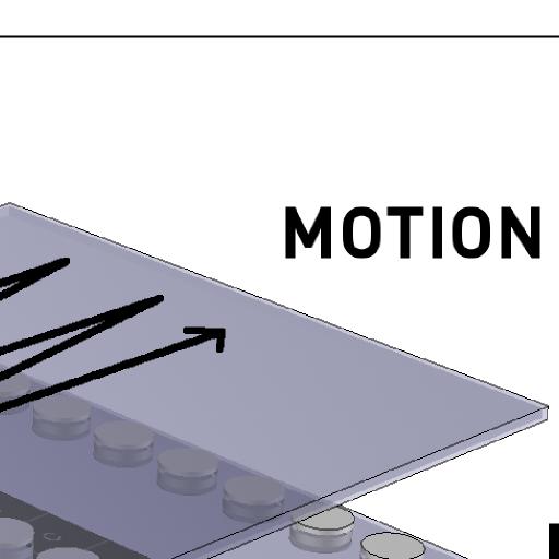
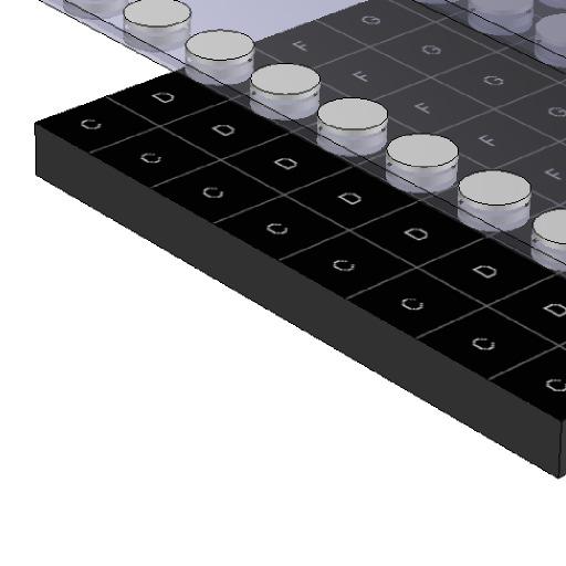
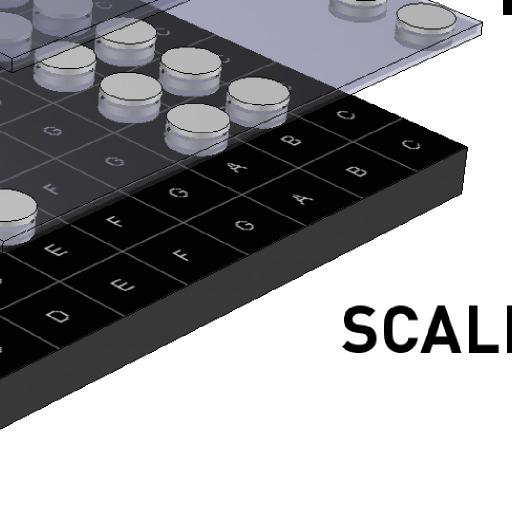
9 // K4815 // Pattern Generator 9p Minor Scale The minor scale spans from C to C without any output offset applied. The Dorian minor is used. (minor 3rd, natural 6th and minor 7th) Every column has the same notes, but different octaves depending on the setting on the LARGE/SMALL switch. Large Span In the large span mode, four octaves are used. These go from low on the top row, to high in the fourth row. The scales then repeat on the lower half of the grid. Small Span In the small span mode, two octaves are used. The lower octave is on rows 1, 3, 5 and 7. The higher octave is on rows 2, 4, 6 and 8. Scale Mapping (All Modes) C D E F G A B C C D E F G A B C C D E F G A B C C D E F G A B C C D E F G A B C C D E F G A B C C D E F G A B C C D E F G A B C UTPUT FFSET Control In CV/GATE mode, the UTPUT FFSET control affects the transposition of the note outputs on CV and MIDI. You can shift the notes up or down by semitones. A full 10 octave range is possible. In /Y mode, the UTPUT FFSET control affects the DC offset of the and Y signals. You can use this control to get the varying signal into the right range for your equipment. The span of the /Y output is -2.5V to +2.5V, so you can shift this up and down. The MIDI CC output of the /Y signal is always the full 7 bit MIDI controller value range, however the offset control adjusts the start point, which wraps around at the ends.

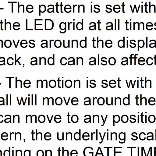
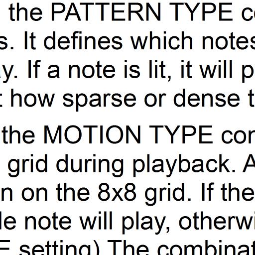
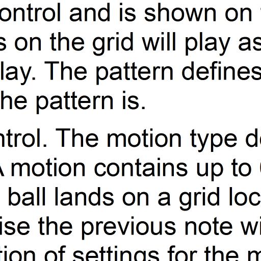
10 // K4815 // Pattern Generator 10p PATTERN TYPE Control The PATTERN TYPE control selects from one of 32 internal patterns which display on the background of the LED matrix and determine which of the underlying scale notes will play when the playback ball lands on them. There is a range of geometric and other special patterns to choose from, all of which provide different kinds of notes and rhythms depending on the motion type used. There is also a pattern with every note enabled which may be useful for testing and hearing different motion patterns and scales in their entirety. MTIN TYPE Control The MTIN TYPE control affects how the playback ball moves around on the display. Each motion type can have up to 64 steps. Each of these steps can land on any position on the grid, and positions can be visited twice, so quite complex motions are possible, not just sequential patterns. There are 64 motion types which are selected by using the MTIN TYPE control. Pressing on the control resets the motion playback position to the first step. When you change motion types, the selected motion is shown on the display briefly in the form of two intersecting lines. The horizontal line represents the row, and the vertical line represents the motion number from 1-8 along that row. This allows all 64 motions to be shown by the intersection of two lines on the grid. The MTIN TYPE can also be set via MIDI program change. Patches 1-64 select the 64 motions available from the front panel of the machine. Patches select the same patches but in "key
11 // K4815 // Pattern Generator 11p trigger" mode, meaning that the motion will only play when MIDI note messages are received (keys pressed) on a MIDI keyboard. This allows the machine to work as an auto-arpeggiator. There are some special motion types which are not pre-programmed, but instead are set randomly. These allow either continually changing random motions, or random motions which are seeded each time the motion is selected, so that repetition of the motion is possible. Preset Motions Preset motions are available from patches These are hand-generated by several collaborators and contain simple linear motions, as well as more complex motions. Motions are up to 64 steps long, but some are less than this based on the particular design concept. Some are visually designed and others are musically designed, taking into account the underlying scale notes to create melodic and arpeggiating patterns. Random Motions In addition to the 48 preset motions, there are also 16 random motion types in locations These are algorithmically created in real-time using a pseudo-random number generator. There are two random motion types with up to eight variations possible for each. See the list below for the variation types. Seeded Random All 64 possible steps are seeded with random values once. Subsequent playback causes the same motion to be repeated. Totally Random Each motion step is generated new every time. This creates a constantly changing random sequence.
12 // K4815 // Pattern Generator 12p Motion List 1 - Sequential left to right and top to bottom. 2 - Sequential top to bottom and left to right. 3 - Sequential zig zag left/right from top to bottom. 4 - Sequential zig-zag up/down and from left to right. 5 - Jumping from the start. 6 - Crazier jumping from the start. 7 - Spiral 8 - Diagonal zig-zag from bottom left corner. 9 - Skipping zig-zag from bottom right corner Up and down triads ctave jumping 5ths ctave jumping wiggly worm ctave jumping rows of four Wiggles in different directions Preset scatter Preset scatter Preset scatter Ping-pong horizontal mirror reflection Cat Hanon Diagonal zig-zag from bottom right corner Diagonal zig-zag ping-pong from bottom right corner circle 24 - Stars Ropes and knots Squares of different sizes Hurricane shape C-E-G Triad 29 - D-F-A Triad 30 - C-E-G-B Triad 31 - D-F-A-C Triad 32 - C-E-G-C Triads Up/Down 33 - E-C-C-G Triads 34 - F-D-A Triads 35 - The Sound of Five 36 - Slither 37 - Mini Slither 38 - Mini Slither Crossing ver 40 - Groove Groove Groove Groove Groove Groove Groove Groove Groove Seeded Random - Seconds 50 - Seeded Random - Thirds 51 - Seeded Random - Fifths 52 - Seeded Random - Row Seeded Random - Rows 1 and Seeded Random - 1, 2, 3 and Seeded Random - 1, 2, 5 and Seeded Random - All Notes 57 - Totally Random - Seconds 58 - Totally Random - Thirds 59 - Totally Random - Fifths 60 - Totally Random - Row Totally Random - Rows 1 and Totally Random - 1, 2, 3 and Totally Random - 1, 2, 5 and Totally Random - All Notes MTIN LENGTH Control Each motion type can have up to 64 steps. But it can sound interesting to play fewer steps. By turning down the MTIN LENGTH control you can play from 1-64 of the total steps in the motion. The motions will repeat once the end of the motion (or the current length setting) is reached.
13 // K4815 // Pattern Generator 13p MIDI Implementation In addition to analog interfaces available from the front panel, the K4815 fully supports MIDI and provides a number of useful functions that are not available on the front panel. It also provides a useful MIDI clock output which can be used as either a stand-alone MIDI clock generator, or as an analog (5V) clock to MIDI converter. It also provides clock input via MIDI clock, which can be used instead of the analog clock input. Control change and note outputs are supported, as well as note and controller input for transposing the pattern, using key trigger playback mode, and reversing the direction of playback. MIDI Hardware Interface n the back of the K4815 PCB is a 10 pin header labelled as MIDI/TEST. It contains MIDI T and R signals, +5V output, as well as a test pin which places the machine in test mode when jumpered to ground. You can access the MIDI signals via a compatible Kilpatrick Audio MIDI module, or by building your own MIDI interface to attach to the 10 pin connector. Since power is supplied, you can use a single cable to connect a simple MIDI interface, with no main power supply connection required. Note that the signals on the MIDI header are 5V TTL signals and cannot be interfaced directly to MIDI cables without some simple circuitry. Please see the Kilpatrick Audio website for free information about building your own MIDI interface. MIDI Clock Support By sending MIDI clock to the machine while it is in external clock mode, it is possible to synchronize the machine to an external MIDI sequencer or other clock source. The input is divided by the CLCK SPEED control just as with an analog clock input. The clock divider setting will be briefly shown on the display when the CLCK SPEED control is adjusted. When running in any clock mode, MIDI clock is sent to the MIDI output. This means that the machine can be used as a MIDI clock generator (internal clock), or an analog to MIDI clock converter. MIDI Program Change The 64 motion types can be selected by a MIDI program change command received by the machine. Programs 1-64 correspond to the 64 patterns selectable by the MTIN TYPE control. Programs correspond to the same 64 patterns, except that keyboard trigger mode is enabled. Keyboard trigger mode allows the playback of a motion to be started when a key is pressed, to use the K4815 as a sort of auto-arpeggiator. MIDI Note Support When in CV/GATE output mode, MIDI notes corresponding to the ones being sent from the CV and gate outputs will be sent. The note length and transposition are the same as the analog outputs. Notes received by the machine from an external MIDI keyboard will transpose the currently playing notes. Middle C is treated as the default transposition. Any notes higher or lower will shift the note playback by the corresponding number of semitones away from middle C.
14 // K4815 // Pattern Generator 14p When one of the patches from are selected, notes received by the K4815 will trigger the start of playback at the beginning of the motion sequence. If you play legato, the notes will be transposed, but the motion will continue playing through to the end before repeating. If you play staccato, the motion will restart from the beginning for each note. MIDI Controller Change Input Several parameters of the K4815 can be controlled via MIDI CC. Pattern Type CC 20 The Pattern Type input allows the current pattern to be adjusted by a voltage. The pattern type input will only increase the pattern type up from the current setting. A CC value of will select patterns For the full range of control turn the PATTERN TYPE control all the way down. Note that you must set the CC value to 0 if you want full manual control over the pattern type. Motion Start CC 21 The motion start has no front panel control and defaults to starting at the first position in a motion sequence. Sending a CC of will offset the starting position of a sequence from position 1 to 64. Motion Length CC 22 The motion length is usually adjusted by the front panel MTIN LENGTH control. A CC value of will select the length from 1-64 steps. The CC will only increase the length from the current value set on the MTIN LENGTH control. For complete CC control it is necessary to turn the MTIN LENGTH control all the way down. MIDI Controller Change utput While in /Y output mode, instead of transmitting MIDI notes, continuous controller messages will be sent. Controllers 16 and 17 correspond to the and Y values of the playback ball respectively. The LARGE/SMALL switch affects the size of the output, and the MAJ/MIN affects the polarity of the output voltages. When MIDI controller 64 (damper pedal) is received the current playback direction is reversed just as with the analog DIR input. MIDI SYSE Messages A series of SYSE messages are used for software updating and loading new motions, patterns and scales. The feature is supported with the use of the free KPatternEdit software from Kilpatrick Audio. A MIDI interface such as the K1600 or KMIDI module is required to connect your computer to the K4815. To use the KPatternEdit software please visit:
15 // K4815 // Pattern Generator 15p Internal Connector Pinouts To assist in making correct connections, and to aid in the creation of compatible adaptor circuits, the internal pin headers are documented here. Please note that 8 is a factory setup connector only and should not be used. Both 6 and 7 connectors are 0.100" pitch pin headers. Standard IDC ribbon cables can be connected. 7 MIDI/Test Connector: 6 Power: 1. GND 2. GND 3. GND 4. GND 5. TEST (ground to activate) 6. MIDI R (input) 7. N/C 8. MIDI T (output) 9. +5V output (50mA max.) V output (50mA max.) Notes: MIDI R and T use 5V TTL signal levels. External MIDI interface circuitry is required. MIDI R is internally terminated to +5V with a 10K resistor V input V input 3. GND 4. GND 5. GND 6. GND 7. GND 8. GND V input V input 11. N/C 12. N/C 13. N/C 14. N/C 15. N/C 16. N/C Support and Additional Information Please contact Kilpatrick Audio with additional questions about the K4815 Pattern Generator. We will do our best to help you make the most of your Pattern Generator and welcome your suggestions as to software improvements or ideas for features on new products. Contact: info@kilpatrickaudio.com
16 // K4815 // Pattern Generator 16p K4815 Pattern Generator MIDI IMPLEMENTATIN CHART ver Basic Default Channel Changed Mode Function Transmitted Recognized Remarks Default Messages Altered 1 (default) 1-16 (configured) 1 (default) 1-16 (configured) Note Number Velocity After Touch Keys Ch's Use TEST mode to set the MIDI R channel. Echoed from input Pitch Bend Echoed from input Control Change 16 = output 17 = Y output 64 = DIR input Prog Change True # / 0-63 Upper bank has "key trigger" enabled. System Exclusive During bootup for software update only. System Common System Realtime Aux Messages Notes Song Position Song Select Tune Request Clock Commands Local n/ff All Notes ff Active Sensing System Reset MIDI clock timeout is 5 seconds. Software update specification available upon request. Implemented by Kilpatrick Audio update software as supplied to customers.
// K4815 // Pattern Generator. User Manual. Hardware Version D/E Firmware Version 1.1x February 16, 2011 Kilpatrick Audio
 // K4815 // Pattern Generator Kilpatrick Audio // K4815 // Pattern Generator 2p Introduction Welcome to the wonderful world of the K4815 Pattern Generator. The K4815 is a unique and flexible way of generating
Shifty Manual v1.00. Shifty. Voice Allocator / Hocketing Controller / Analog Shift Register
 Shifty Manual v1.00 Shifty Voice Allocator / Hocketing Controller / Analog Shift Register Table of Contents Table of Contents Overview Features Installation Before Your Start Installing Your Module Front
Shifty Manual. Shifty. Voice Allocator Hocketing Controller Analog Shift Register Sequential/Manual Switch. Manual Revision:
 Shifty Voice Allocator Hocketing Controller Analog Shift Register Sequential/Manual Switch Manual Revision: 2018.10.14 Table of Contents Table of Contents Compliance Installation Installing Your Module
ALGORHYTHM. User Manual. Version 1.0
 !! ALGORHYTHM User Manual Version 1.0 ALGORHYTHM Algorhythm is an eight-step pulse sequencer for the Eurorack modular synth format. The interface provides realtime programming of patterns and sequencer
Polyend Poly Polyphonic MIDI to CV Converter User Manual
 Polyend Poly Polyphonic MIDI to CV Converter User Manual Made in Poland polyend.com Polyend Poly Polyphonic MIDI to CV Converter in the Eurorack format Poly is probably the easiest entry point for exploring
Written by Jered Flickinger Copyright 2019 Future Retro
 Written by Jered Flickinger Copyright 2019 Future Retro www.future-retro.com 2 TABLE OF CONTENTS Page 4 - Overview Page 5 Controls Page 6 Inputs and Outputs Page 7 MIDI Page 8 Jumper Settings Page 9 Standalone
multitrack sequencer USER GUIDE Social Entropy Electronic Music Instruments
 multitrack sequencer Social Entropy Electronic Music Instruments IMPORTANT SAFETY AND MAINTENANCE INSTRUCTIONS TABLE OF CONTENTS BACKGROUND... 1 CONCEPTS... 2 DIAGRAM CONVENTIONS... 3 THE BASICS WHAT
ADE-32 OCTOCONTROLLER
 ADE-32 OCTOCONTROLLER Control, Modulation, Triggering and Pattern module with 12 Output Types individually assignable to 8 simultaneous Outputs. USER GUIDE 2016 Abstract Data Ltd. http://www.abstractdata.biz
Noise Tools 1U Manual. Noise Tools 1U. Clock, Random Pulse, Analog Noise, Sample & Hold, and Slew. Manual Revision:
 Noise Tools 1U Clock, Random Pulse, Analog Noise, Sample & Hold, and Slew Manual Revision: 2018.05.16 Table of Contents Table of Contents Overview Installation Before Your Start Installing Your Module
Quad Clock Distributor (QCD) from 4ms Company
 from 4ms Company") Quad Clock Distributor (QCD) from 4ms Company Eurorack Module User Manual v1.0 (2013-12-09) The Quad Clock Distributor (QCD) from 4ms Company is a four channel Voltage Controlled Clock Divider/Multiplier
Quad Clock Distributor (QCD) from 4ms Company Eurorack Module User Manual v1.0 (2013-12-09) The Quad Clock Distributor (QCD) from 4ms Company is a four channel Voltage Controlled Clock Divider/Multiplier
randomrhythm Bedienungsanleitung User Guide
 randomrhythm Bedienungsanleitung User Guide EN Foreword Whether random really exists or is just an illusion, shall be discussed by philosophers and mathematicians. At VERMONA, we found a possibility to
VARIGATE 4+ MANUAL V.1
 www.malekkoheavyindustry.com 814 SE 14TH AVENUE PORTLAND OR 97214 USA TABLE OF CONTENTS SPECIFICATIONS 1 INSTALLATION 2 DESCRIPTION 3 OVERVIEW 4-5 PROGRAMMING GATES PER STEP 6 PROGRAMMING CV/NOTES PER
fxbox User Manual P. 1 Fxbox User Manual
 fxbox User Manual P. 1 Fxbox User Manual OVERVIEW 3 THE MICROSD CARD 4 WORKING WITH EFFECTS 4 MOMENTARILY APPLY AN EFFECT 4 TRIGGER AN EFFECT VIA CONTROL VOLTAGE SIGNAL 4 TRIGGER AN EFFECT VIA MIDI INPUT
Noise Tools 1U Manual. Noise Tools 1U. Clock, Random Pulse, Analog Noise, Sample & Hold, and Slew. Manual Revision:
 Noise Tools 1U Clock, Random Pulse, Analog Noise, Sample & Hold, and Slew Manual Revision: 2018.09.13 Table of Contents Table of Contents Compliance Installation Before Your Start Installing Your Module
MantaMate User Manual. Snyderphonics
 MantaMate User Manual Snyderphonics Version 0.7, July 30, 2017 Contents Preface 1 Setting up the MantaMate 1 1.1 Connecting Power......................... 1 1.2 Output Voltage Range Jumper..................
R H Y T H M G E N E R A T O R. User Guide. Version 1.3.0
 R H Y T H M G E N E R A T O R User Guide Version 1.3.0 Contents Introduction... 3 Getting Started... 4 Loading a Combinator Patch... 4 The Front Panel... 5 The Display... 5 Pattern... 6 Sync... 7 Gates...
Limited WARRANTY: Make Noise implies and accepts no responsibility for harm to person or apparatus caused through operation of this product.
 v2.4 1 BRAINS Limited Warranty: ----------------------------------------------------2 Installation: --------------------------------------------------3 Jumpers and Cable Connections: --------------------------------4
Oberkorn User Manual. Analogue Sequencer. Analogue Solutions
 Oberkorn User Manual Analogue Sequencer Analogue Solutions CONTENTS What is an analogue sequencer?... 4 That s all very well (and technical) but what would I use it for?... 4 ABOUT THIS MANUAL AND ABOUT
User Guide. Version 2.0.0
 II User Guide Version 2.0.0 Contents Introduction... 3 What s New in Step Note Recorder II?... 3 Getting Started... 4 The Front Panel... 5 The Sequence... 5 The Piano Roll... 6 The Data Lane... 7 Velocity...
Vorne Industries. 87/719 Analog Input Module User's Manual Industrial Drive Itasca, IL (630) Telefax (630)
 Telefax (630)") Vorne Industries 87/719 Analog Input Module User's Manual 1445 Industrial Drive Itasca, IL 60143-1849 (630) 875-3600 Telefax (630) 875-3609 . 3 Chapter 1 Introduction... 1.1 Accessing Wiring Connections
Vorne Industries 87/719 Analog Input Module User's Manual 1445 Industrial Drive Itasca, IL 60143-1849 (630) 875-3600 Telefax (630) 875-3609 . 3 Chapter 1 Introduction... 1.1 Accessing Wiring Connections
ADE-60 4:4 MIX UTILITY
 ADE-60 4:4 MIX UTILITY Cascading, 4-Channel, Mix & CV Utility with user-configurable options for 2x Gain, Attenuversion, Biasing & CV. 2017 Abstract Data Ltd. http://www.abstractdata.biz Version 1.0.2
Edit Menu. To Change a Parameter Place the cursor below the parameter field. Rotate the Data Entry Control to change the parameter value.
 The Edit Menu contains four layers of preset parameters that you can modify and then save as preset information in one of the user preset locations. There are four instrument layers in the Edit menu. See
rhythmic step sequencer user manual
 rhythmic step sequencer user manual Analogue Solutions Generator Manual Introduc)on... 3 Generator Layout... 4 Generator:... 5 MIDI (DAW Use) or CV & Gate?... 5 Feature Overview... 5 What will it work
NAVIGATOR OWNER S MANUAL
 OWNER S MANUAL UNCHARTED WATERS, NEW HORIZONS Making shapes spin and move is notoriously difficult for pattern synthesis based only on oscillators synchronized to horizontal and vertical frequency ranges.
Pressure Points. v. 2.5
 Pressure Points v. 2.5 2 Pressure Points FCC-------------------------------------------------------------------3 Limited Warranty ----------------------------------------------------4 Installation ----------------------------------------------------5
QUAD ENVELOPE MANUAL V.1
 www.malekkoheavyindustry.com 814 SE 14TH AVENUE PORTLAND OR 97214 USA TABLE OF CONTENTS SPECIFICATIONS 1 INSTALLATION 2 DESCRIPTION 3 CONTROLS 4-6 MEASUREMENTS 7 USING QUAD ENVELOPE WITH VARIGATE 8+ AND
Limited WARRANTY: Make Noise implies and accepts no responsibility for harm to person or apparatus caused through operation of this product.
 v2.5 2 BRAINS Limited Warranty ----------------------------------------------------3 Installation --------------------------------------------------4 Jumpers and Cable Connections --------------------------------5
NoteMix Player Note Mixer/Shifter/Splitter/Filter with Snapshot Morphing Rack Extension for Propellerhead Reason
 NoteMix Player Note Mixer/Shifter/Splitter/Filter with Snapshot Morphing Rack Extension for Propellerhead Reason USER MANUAL version 1.0.0 NoteMix User Manual www.retouchcontrol.com Page 1 of 26 Table
Tetrapad Manual. Tetrapad. Multi-Dimensional Performance Touch Controller. Firmware: 1.0 Manual Revision:
 Tetrapad Multi-Dimensional Performance Touch Controller Firmware: 1.0 Manual Revision: 2017.11.15 Table of Contents Table of Contents Overview Installation Before Your Start Installing Your Module Panel
Tiptop audio z-dsp.
 Tiptop audio z-dsp www.tiptopaudio.com Introduction Welcome to the world of digital signal processing! The Z-DSP is a modular synthesizer component that can process and generate audio using a dedicated
Modcan Touch Sequencer Manual
 Modcan Touch Sequencer Manual Normal 12V operation Only if +5V rail is available Screen Contrast Adjustment Remove big resistor if using with PSU with 5V rail Jumper TOP VEIW +5V (optional) +12V } GND
DCB mk 3. professional bi-directional MIDI to DCB converter. Operating manual
 PRO-DCB DCB mk 3 professional bi-directional to DCB converter Operating manual INTRODUCTION The PRO DCB mk3 is much more than just a to DCB converter, incorporating a builtin LFO as well as filter and
Rhythm. Pattern Generator
 Rhythm Pattern Generator Description The Rhythm is a 4 channel pattern generator with BPM display. It ships with a multitude of genre-oriented rhythms that can be altered on a per channel basis. With each
Intelligent Quantizer and Interval Generator
 µscale Intelligent Quantizer and Interval Generator Manual Revision: 2018.02.16 Table of Contents Table of Contents Overview Features Installation Before Your Start Installing Your Module Front Panel Controls
MANUAL v.3 CONTACT MORE THAN LOGIC. UNITING ART + ENGINEERING.
 MANUAL v.3 MORE THAN LOGIC. UNITING ART + ENGINEERING. CONTACT email: info@meris.us phone: 747.233.1440 website: www.meris.us TABLE OF CONTENTS SECTION 1 PG. 1 FRONT PANEL CONTROLS SECTION 2 PG. 2-4 GLOBAL
User Guide Version 1.1.0
 obotic ean C R E A T I V E User Guide Version 1.1.0 Contents Introduction... 3 Getting Started... 4 Loading a Combinator Patch... 5 The Front Panel... 6 On/Off... 6 The Display... 6 Reset... 7 Keys...
LED Array Board.
 LED Array Board www.matrixtsl.com EB087 Contents About This Document 2 General Information 3 Board Layout 4 Testing This Product 5 Circuit Description 6 Circuit Diagram 7 About This Document This document
QUAD LFO MANUAL V SE 14TH AVENUE PORTLAND OR USA
 www.malekkoheavyindustry.com 814 SE 14TH AVENUE PORTLAND OR 97214 USA TABLE OF CONTENTS SPECIFICATIONS 1 INSTALLATION 2 DESCRIPTION 3 CONTROLS 4-6 USING QUAD LFO WITH VARIGATE 8+ AND VARIGATE 4+ 7 WARRANTY
TV Character Generator
 TV Character Generator TV CHARACTER GENERATOR There are many ways to show the results of a microcontroller process in a visual manner, ranging from very simple and cheap, such as lighting an LED, to much
Start/Stop works in each mode, and puts the pattern back to the starting point step 1 of the current pattern.
 Sequencer Modes In all six modes the playing of the sequencer is guaranteed. You can change the modes, while the sequencer is running. Switching into another mode, takes place after the last step of the
oberkorn3 analogue sequencer user manual analogue sequencer user manual ANALOGUE SOLUTIONS oberkorn mkiii e&oe (c)
") oberkorn3 analogue sequencer user manual analogue sequencer user manual ANALOGUE SOLUTIONS oberkorn mkiii e&oe (c) 10-2006 1 Contents Intro - OBERKORN - Professional Analogue Sequencer...4 About Analogue
oberkorn3 analogue sequencer user manual analogue sequencer user manual ANALOGUE SOLUTIONS oberkorn mkiii e&oe (c) 10-2006 1 Contents Intro - OBERKORN - Professional Analogue Sequencer...4 About Analogue
Audio Interface II Manual. Audio Interface II. Eurorack <-> Line Level Audio Interface. Manual Revision: 1.0
 Audio Interface II Eurorack Line Level Audio Interface Manual Revision: 1.0 Overview The Audio Interface II allows you to interface your Eurorack modular system to the pro balanced line level world
A BBD replacement and adjustment procedure
 A-188-1 BBD replacement and adjustment procedure The following steps have to be carried out with the unpowered A-188-1 module (i.e. the module is not connected to the A-100 bus board or the module is connected
BINARY Zone. BLACET RESEARCH MODEL BZ2300 Binary Zone Module. User Manual
 BINARY Zone BLACET RESEARCH MODEL BZ2300 Binary Zone Module User Manual Blacet Research 15210 Orchard Rd Guerneville CA 95446 blacet@blacet.com http://www.blacet.com 707-869-9164 Contents Copyright. Reproduction
Chapter 5 Flip-Flops and Related Devices
 Chapter 5 Flip-Flops and Related Devices Chapter 5 Objectives Selected areas covered in this chapter: Constructing/analyzing operation of latch flip-flops made from NAND or NOR gates. Differences of synchronous/asynchronous
Dave Jones Design Phone: (607) Lake St., Owego, NY USA
 Lake St., Owego, NY USA") Manual v1.00a June 1, 2016 for firmware vers. 2.00 Dave Jones Design Phone: (607) 687-5740 34 Lake St., Owego, NY 13827 USA www.jonesvideo.com O Tool Plus - User Manual Main mode NOTE: New modules are
Manual v1.00a June 1, 2016 for firmware vers. 2.00 Dave Jones Design Phone: (607) 687-5740 34 Lake St., Owego, NY 13827 USA www.jonesvideo.com O Tool Plus - User Manual Main mode NOTE: New modules are
PSM-003. Micro Polarization Controller/Scrambler. User Guide
 PSM-003 Micro Polarization Controller/Scrambler User Guide Version: 1.0 Date: August 23, 2012 General Photonics, Incorporated is located in Chino California. For more information visit the company's website
RE-303 CPU. SONIC-POTIONS!!! PRELIMINARY DRAFT!!! v WORK IN PROGRESS
 RE-303 CPU SONIC-POTIONS!!! PRELIMINARY DRAFT!!! v 0.911 WORK IN PROGRESS Intro... 3 Quickstart... 3 The random way... 3 The manual way...3 Control scheme... 4 Pattern Write Mode... 4 Auto Exit... 4 Normal
MIDI2DMX PRO. solid state MIDI to DMX converter. wwww.midi2dmx.eu
 MIDI2DM PRO solid state MIDI to DM converter wwww.midi2dmx.eu May 2011 From the authors Artistic and stage activity is like others aspects of our life - competition on the market is everywhere. On the
SignalTap Plus System Analyzer
 SignalTap Plus System Analyzer June 2000, ver. 1 Data Sheet Features Simultaneous internal programmable logic device (PLD) and external (board-level) logic analysis 32-channel external logic analyzer 166
StepSequencer64 J74 Page 1. J74 StepSequencer64. A tool for creative sequence programming in Ableton Live. User Manual
 StepSequencer64 J74 Page 1 J74 StepSequencer64 A tool for creative sequence programming in Ableton Live User Manual StepSequencer64 J74 Page 2 How to Install the J74 StepSequencer64 devices J74 StepSequencer64
Sequencer 1 User s Guide
 Sequencer 1 User s Guide Audio Damage, Inc. For Firmware Version 1.5.0 22 December 2016 The information in this document is subject to change without notice and does not represent a commitment on the part
Plog rev 1.0 MANUAL Overview
 Overview The Intellijel Plog is a voltage controllable digital logic device designed for musical applications. It is primarily intended to create controllable patterns from gate/ pulse sources like clocks
Table of contents E 1
 Table of contents Introduction...2 monologue Key Features... 2 Block Diagram... 3 Controls and Connections...4 Front Panel Controls... 4 Rear Panel Connections... 5 Turning the monologue n and ff... 6
Intelligent Security and Fire Ltd
 User Manual Product ranges covered by this manual Vi-P14 Vi-P14A Document Reference Date Firmware Vi-Q4C1 Viq601a.doc 26/11/2009 From Viq001a21 Videoswitch Telephone 01252-851510 Ocean House, Redfields
Description. Never run out of envelopes again.
 Contour Description Never run out of envelopes again. Contour is a quad envelope generator. Each channel has looping, CV over attack and decay, as well as unique chaining capabilities. This makes for the
C8000. sync interface. External sync auto format sensing : AES, Word Clock, Video Reference
 features Standard sync module for a frame Internal sync @ 44.1 / 48 / 88.2 / 96kHz External sync auto format sensing : AES, Word Clock, Video Reference Video Reference : Black Burst (NTSC or PAL) Composite
2002 Martin Professional A/S, Denmark.
 Freekie user manual 2002 Martin Professional A/S, Denmark. All rights reserved. No part of this manual may be reproduced, in any form or by any means, without permission in writing from Martin Professional
Vorne Industries. 2000B Series Buffered Display Users Manual Industrial Drive Itasca, IL (630) Telefax (630)
 Telefax (630)") Vorne Industries 2000B Series Buffered Display Users Manual 1445 Industrial Drive Itasca, IL 60141849 (60) 875600 elefax (60) 875609 Page 2 2000B Series Buffered Display 2000B Series Buffered Display Release
Vorne Industries 2000B Series Buffered Display Users Manual 1445 Industrial Drive Itasca, IL 60141849 (60) 875600 elefax (60) 875609 Page 2 2000B Series Buffered Display 2000B Series Buffered Display Release
16-BIT LOAD CELL/DUAL STATUS INPUT
 16-BIT LOAD CELL/DUAL STATUS INPUT On-board Excitation. +5VDC, (120mA). State-of-the-art Electromagnetic Noise Suppression Circuitry. Ensures signal integrity even in harsh EMC environments. Optional Excitation
1. Welcome To BeatChop
 1. Welcome To BeatChop Thank you for purchasing BeatChop Realtime Slicer & Rearranger Rack Extension for Propellerhead Reason. We would like to welcome you to our first Creative Effect for the Reason Rack.
LS1lightstrip User s Manual. Introduction Care and feeding Specifications. soundmachines user manual 1 LS1lightstrip
 User s Manual Introduction Care and feeding Specifications soundmachines user manual 1 Introduction The is a capacitive slider that will generate CV and GATE signals along with the movement of your finger
bindubba1 The only real rule with nonlinearcircuits panels is BLUE jacks = INPUT RED jacks = OUTPUT
 The two sequencers are happy to operate independently of each other but for greater entertainment and general synchronised lunacy it is good to couple them. In which case usually bindubba1 is the top and
Audio Interface II Manual. Audio Interface II. Eurorack <-> Line Level Audio Interface. Manual Revision:
 Audio Interface II Eurorack Line Level Audio Interface Manual Revision: 2018.09.13 Table of Contents Table of Contents Compliance Installation Installing Your Module Overview Features Front Panel Controls
Introduction Display...1 Mounting...1 Firmware Version...2. ADL Operation... 3
 MoTeC MDD User Manual Contents Introduction... 1 Display...1 Mounting...1 Firmware Version...2 ADL Operation... 3 1. Full ADL Display...4 2. Gain Loss Layout for ADL...6 3. Large Numeric Layout for ADL...8
GUIDE TO ASSEMBLY OF ERICA SYNTHS DELAY MODULE
 If you are reading this, most probably, you are about to build Erica Synths DIY DELAY module. The module is 4mm deep, skiff friendly, has solid mechanical construction and doesn t require wiring. Erica
Polyend Seq MIDI Step Sequencer User Manual
 Polyend Seq MIDI Step Sequencer User Manual Made in Poland polyend.com Introduction Thank you for purchasing the Polyend Seq. We at Polyend have invested a lot of our attention, time, and hearts in crafting
Industriefunkuhren. Technical Manual. IRIG-B Generator-Module for analogue / digital Signals of Type: IRIG-B / IEEE C / AFNOR NF S87-500
 Industriefunkuhren Technical Manual IRIG-B Generator-Module for analogue / digital Signals of Type: IRIG-B / IEEE C37.118 / AFNOR NF S87-500 Module 7628 ENGLISH Version: 02.01-06.03.2013 2 / 20 7628 IRIG-B
Solid State Logic S O U N D V I S I O N
 Solid State Logic S O U N D V I S I O N SUPERANALOGUE X - R A C K Super-Analogue Outboard XR622 X-Rack Master Module User s Guide This documentation package contains the User s Guide for your new X-Rack
SND ACME-4 Advanced Clock Management Engine operating instructions. March 6, 2012
 SND ACME-4 Advanced Clock Management Engine operating instructions March 6, 2012 Contents 1 Introduction 4 2 Quick Reference 5 3 Connections 6 3.1 Inputs............................................. 6
Table of Contents: ECHOPHON
 v2.6 Table of Contents: 2 ECHOPHON FCC -----------------------------------------------------3 Limited Warranty ----------------------------------------4 Installation --------------------------------------------------5
Absolute Encoders Multiturn
 The Sendix 5863 and 5883 multiturn encoders with SSI or BiSS-C interface and optical sensor technology can achieve a resolution of max. 29 bits. A through hollow shaft up to 4 mm and a blind hollow shaft
Synthesis Technology E102 Quad Temporal Shifter User Guide Version 1.0. Dec
 Synthesis Technology E102 Quad Temporal Shifter User Guide Version 1.0 Dec. 2014 www.synthtech.com/euro/e102 OVERVIEW The Synthesis Technology E102 is a digital implementation of the classic Analog Shift
Limited WARRANTY: Make Noise implies and accepts no responsibility for harm to person or apparatus caused through operation of this product.
 Rosie Limited WARRANTY: Make Noise warrants this product to be free of defects in materials or construction for a period of one year from the date of purchase (proof of purchase/invoice required). Malfunction
Installation / Set-up of Autoread Camera System to DS1000/DS1200 Inserters
 Installation / Set-up of Autoread Camera System to DS1000/DS1200 Inserters Written By: Colin Langridge Issue: Draft Date: 03 rd July 2008 1 Date: 29 th July 2008 2 Date: 20 th August 2008 3 Date: 02 nd
For example, an indication of Range: 60, 67, 72, 75 (Hz) means that 60 Hz is the default value.
 means that 60 Hz is the default value.") Owner s Manual This manual explains how to use an MV-8000 in which System Program Version 3.0 is installed. About the Symbols and icons in this manual Text in square brackets [ ] refers to buttons on the
Owner s Manual This manual explains how to use an MV-8000 in which System Program Version 3.0 is installed. About the Symbols and icons in this manual Text in square brackets [ ] refers to buttons on the
Mackie Control and Cubase SX/SL
 Mackie Control and Cubase SX/SL - 1 - The information in this document is subject to change without notice and does not represent a commitment on the part of Steinberg Media Technologies AG. The software
DX-10 tm Digital Interface User s Guide
 DX-10 tm Digital Interface User s Guide GPIO Communications Revision B Copyright Component Engineering, All Rights Reserved Table of Contents Foreword... 2 Introduction... 3 What s in the Box... 3 What
SM DMX LIGHTING CONTROLLER OWNERS MANUAL. May 19, 2009
 SM - 192 DMX LIGHTING CONTROLLER OWNERS MANUAL May 19, 2009 INSTRUCTION MANUAL Page 2 of 8 MAIN FEATURES 192 DMX Channels 30 Scene Banks of 8 programmable scenes each 6 Programmable chases with up to 240
ROSIE Limited Warranty Installation
 v2.3 2 ROSIE Limited Warranty -----------------------------------------------------3 Installation ----------------------------------------------------------------4 Panel Controls ---------------------------------------------------------------5
Introduction. NAND Gate Latch. Digital Logic Design 1 FLIP-FLOP. Digital Logic Design 1
 2007 Introduction BK TP.HCM FLIP-FLOP So far we have seen Combinational Logic The output(s) depends only on the current values of the input variables Here we will look at Sequential Logic circuits The
LED DRIVERS. LQC4D-V1 4 channels. User Manual FEATURES
 pag. 1/13 FEATURES Outputs: 4 x channels BUS+SEQUENCER+FADER+DIMMER+DRIVER Input: DC 12/24/48 Vdc BUS Command: DALI LOCAL Command: 4x N.O. push button (with or without memory), 0-10V, 1-10V Controls: dimmer,
CoLinkEx JTAG/SWD adapter USER MANUAL
 CoLinkEx JTAG/SWD adapter USER MANUAL rev. A Website: www.bravekit.com Contents Introduction... 3 1. Features of CoLinkEX adapter:... 3 2. Elements of CoLinkEx programmer... 3 2.1. LEDs description....
Chapter 23 Dimmer monitoring
 Chapter 23 Dimmer monitoring ETC consoles may be connected to ETC Sensor dimming systems via the ETCLink communication protocol. In this configuration, the console operates a dimmer monitoring system that
Industriefunkuhren. Technical Manual. OEM Sync-Module FE1000 (IRIG-B) ENGLISH
 ENGLISH") Industriefunkuhren Technical Manual OEM Sync-Module FE1000 (IRIG-B) ENGLISH Version: 07.02-24.03.2014 2 / 19 FE1000 IRIG-B Synchronisation - V07.02 IMPORTANT NOTES Version Number (Firmware / Manual) THE
Industriefunkuhren Technical Manual OEM Sync-Module FE1000 (IRIG-B) ENGLISH Version: 07.02-24.03.2014 2 / 19 FE1000 IRIG-B Synchronisation - V07.02 IMPORTANT NOTES Version Number (Firmware / Manual) THE
SATELLITE. Universal CV Generator. Operation Manual. v2.1_ Copyright 2017 Rossum Electro-Music LLC
 SATELLITE Universal CV Generator Operation Manual v2.1_060117 Copyright 2017 Rossum Electro-Music LLC www.rossum-electro.com Contents 1. Introduction 3 2. Module Installation 4 3. Overview 5 4. How to
FLIP-FLOPS AND RELATED DEVICES
 C H A P T E R 5 FLIP-FLOPS AND RELATED DEVICES OUTLINE 5- NAND Gate Latch 5-2 NOR Gate Latch 5-3 Troubleshooting Case Study 5-4 Digital Pulses 5-5 Clock Signals and Clocked Flip-Flops 5-6 Clocked S-R Flip-Flop
SHENZHEN H&Y TECHNOLOGY CO., LTD
 Chapter I Model801, Model802 Functions and Features 1. Completely Compatible with the Seventh Generation Control System The eighth generation is developed based on the seventh. Compared with the seventh,
1. Introduction. A-160 CLOCK DIVIDER Trig. In Res. In. doepfer System A Clock Divider A-160
 doepfer System A - 100 Clock Divider 1. troduction Module (Clock Divider) is a frequency divider for clock signals, designed to be a source of lower frequencies, particularly for rhythm uses. The Trigger
Kramer Electronics, Ltd. USER MANUAL. Models: VS-626, 6x6 Video / Audio Matrix Switcher VS-828, 8x8 Video / Audio Matrix Switcher
 Kramer Electronics, Ltd. USER MANUAL Models: VS-626, 6x6 Video / Audio Matrix Switcher VS-828, 8x8 Video / Audio Matrix Switcher Contents Contents 1 Introduction 1 2 Getting Started 1 2.1 Quick Start 1
XYNTHESIZR User Guide 1.5
 XYNTHESIZR User Guide 1.5 Overview Main Screen Sequencer Grid Bottom Panel Control Panel Synth Panel OSC1 & OSC2 Amp Envelope LFO1 & LFO2 Filter Filter Envelope Reverb Pan Delay SEQ Panel Sequencer Key
Displays AND-TFT-5PA PRELIMINARY. 320 x 234 Pixels LCD Color Monitor. Features
 PRELIMINARY 320 x 234 Pixels LCD Color Monitor The is a compact full color TFT LCD module, whose driving board is capable of converting composite video signals to the proper interface of LCD panel and
Agilent Technologies. N5106A PXB MIMO Receiver Tester. Error Messages. Agilent Technologies
 Agilent Technologies N5106A PXB MIMO Receiver Tester Messages Agilent Technologies Notices Agilent Technologies, Inc. 2008 2009 No part of this manual may be reproduced in any form or by any means (including
V DD V DD V CC V GH- V EE
 N/A 480 x 468 Pixels LCD Color Monitor The is a compact full color TFT LCD module, whose driving board is capable of converting composite video signals to the proper interface of LCD panel and is suitable
KAMIENIEC. analog resonant phase rotator. Model of operator s manual rev. 1977/1.0
 KAMIENIEC analog resonant phase rotator operator s manual rev. 1977/1.0 Model of 1977 module explained 20 SALUT Thank you for purchasing this Xaoc Devices product. Kamieniec is an analog signal processing
A-134 VC Panning Module
 doepfer System A - 100 Voltage Controlled Panning A-134 1. Introduction A-134 VC Panning Module CV 1 Pan Module A-134 (PAN) is designed to provide voltagecontrolled panning for audio signals. It can equally
III Phrase Sampler. User Manual
 III Phrase Sampler User Manual Version 3.3 Software Active MIDI Sync Jun 2014 800-530-4699 817-421-2762, outside of USA mnelson@boomerangmusic.com Boomerang III Phrase Sampler Version 3.3, Active MIDI
UARP. User Guide Ver 2.2
 UARP Ver 2.2 UArp is an innovative arpeggiator / sequencer suitable for many applications such as Songwriting, Producing, Live Performance, Jamming, Experimenting, etc. The idea behind UArp was to create
DP-25 digital piano. user manual
 DP-25 digital piano user manual Musikhaus Thomann e.k. Treppendorf 30 96138 Burgebrach Germany Telephone: +49 (0) 9546 9223-0 E-mail: info@thomann.de Internet: www.thomann.de 25.02.2013 Table of contents
DMX48. User s instruction manual. 24 Channel DMX controller
 WWW.LIGHTEMOTIONS.COM.AU DMX48 24 Channel DMX controller User s instruction manual This manual contains important information about the safe installation and use of this product Please read this instruction