Sequential Logic. Introduction to Computer Yung-Yu Chuang
|
|
|
- Juniper Charles
- 6 years ago
- Views:
Transcription
1 Sequential Logic Introduction to Computer Yung-Yu Chuang with slides by Sedgewick & Wayne (introcs.cs.princeton.edu), Nisan & Schocken ( and Harris & Harris (DDCA)
2 Review of Combinational Circuits Combinational circuits. Basic abstraction = switch. In principle, can build TOY computer with a combinational circuit = 4,080 inputs rows in truth table! no simple pattern each circuit element used at most once Sequential circuits. Reuse circuit elements by storing bits in "memory." ALU combinational Memory state 2

3 Combinational vs. Sequential Circuits Combinational circuits. Output determined solely by inputs. Can draw with no loops. Ex: majority, adder, ALU. Sequential circuits. Output determined by inputs and previous outputs. Ex: memory, program counter, CPU. 3
4 Flip-flop Flip-Flop A small and useful sequential circuit Abstraction that remembers one bit Basis of important computer components for register memory counter There are several flavors 4
5 S-R flip flop R S Q Q=S+RQ 5

6 Relay-based flip-flop Ex. Simplest feedback loop. Two relays A and B, both connected to power, each blocked by the other. State determined by whichever switches first. The state is latched. Stable. output1 input2 input1 output2 6


 Q")
7 SR Flip Flop SR flip flop. Two cross-coupled NOR gates. R S Q=R(S+Q) Q R S Q
8 Flip-flop. Flip-Flop A way to control the feedback loop. Abstraction that "remembers" one bit. Basic building block for memory and registers. Caveat. Need to deal with switching delay. 8
9 Truth Table and Timing Diagram Truth table. Values vary over time. S(t), R(t), Q(t) denote value at time t. Sample timing diagram for SR flip-flop. SR Flip Flop Truth Table S(t) R(t) Q(t) Q(t+ ) Q R S time
10 Clock. Clock Fundamental abstraction: regular on-off pulse. on: fetch phase off: execute phase External analog device. Synchronizes operations of different circuit elements. Requirement: clock cycle longer than max switching time. cycle time on Clock off 10
 means 1 million cycles/sec. 1 gigahertz (GHz) means 1 billion cycles/sec. 1 terahertz (THz) means 1 trillion cycles/sec. Heinrich Rudolf Hertz (1857-1894) 11")
11 How much does it Hert? Frequency is inverse of cycle time. Expressed in hertz. Frequency of 1 Hz means that there is 1 cycle per second. 1 kilohertz (khz) means 1000 cycles/sec. 1 megahertz (MHz) means 1 million cycles/sec. 1 gigahertz (GHz) means 1 billion cycles/sec. 1 terahertz (THz) means 1 trillion cycles/sec. Heinrich Rudolf Hertz ( ) 11
12 Clocked S-R flip-flop 12
13 Clocked D flip-flop 13
14 Stand-Alone Register 14
15 Register file interface 15
16 Register file implementation 16
 (X S) X Y S mux Z Two-input multiplexer")
17 Multiplexer When s=0, return x; otherwise, return y. Example: (Y S) (X S) X Y S mux Z Two-input multiplexer 17
18 4-to-1 multiplexer x 0 x 1 x 2 4MUX z x 3 s 0 s 1 18
19 4-to-1 multiplexer x 0 x 0 x 1 2MUX x 1 x 2 4MUX z 2MUX z x 3 x 2 x 3 2MUX s 0 s 1 s 0 s 1 19
20 8-to-1 Multiplexer 2 N -to-1 multiplexer N select inputs, 2 N data inputs, 1 output Copies selected data input bit to output 20

21 8-to-1 Multiplexer 2 N -to-1 multiplexer N select inputs, 2 N data inputs, 1 output Copies selected data input bit to output 21
22 4-Wide 2-to-1 Multiplexer Goal: select from one of two 4-bit buses 22

23 4-Wide 2-to-1 Multiplexer Goal: select from one of two 4-bit buses Implemented by layering 4 2-to-1 multiplexer 23
24 k-wide n-to-1 Multiplexer Goal: select from one of n k-bit buses Implemented by layering k n-to-1 multiplexer 24

25 Register file implementation 25
26 Memory Overview Computers and TOY have several memory components. Program counter. Registers. Main memory. Implementation. Use one flip-flop for each bit of memory. Access. Memory components have different access mechanisms. TOY has 16 bit words, 8 bit memory addresses, and 4 bit register names. Organization. Need mechanism to manipulate groups of related bits. 26


27 Register Bit Register bit. Extend a flip-flop to allow easy access to values. 27


28 Register Bit Register bit. Extend a flip-flop to allow easy access to values. D W DW DW 28


29 Memory Bit: Interface Memory bit. Extend a flip-flop to allow easy access to values. [ TOY PC, IR ] [ TOY main memory ] [ TOY registers ] 29


30 Memory Bit: Switch Level Implementation Memory bit. Extend a flip-flop to allow easy access to values. [ TOY PC, IR ] [ TOY main memory ] [ TOY registers ] 30
 holds 8-bit address. Ex 2.")
31 Processor register. Stores k bits. Processor Register Register contents always available on output bus. If enable write is asserted, k input bits get copied into register. Ex 1. TOY program counter (PC) holds 8-bit address. Ex 2. TOY instruction register (IR) holds 16-bit current instruction. 31

 holds 8-bit address. Ex 2.")
32 Processor register. Stores k bits. Processor Register Register contents always available on output bus. If enable write is asserted, k input bits get copied into register. Ex 1. TOY program counter (PC) holds 8-bit address. Ex 2. TOY instruction register (IR) holds 16-bit current instruction. 32
 holds 8-bit address. Ex 2.")
33 Processor register. Stores k bits. Processor Register Register contents always available on output bus. If enable write is asserted, k input bits get copied into register. Ex 1. TOY program counter (PC) holds 8-bit address. Ex 2. TOY instruction register (IR) holds 16-bit current instruction. 33

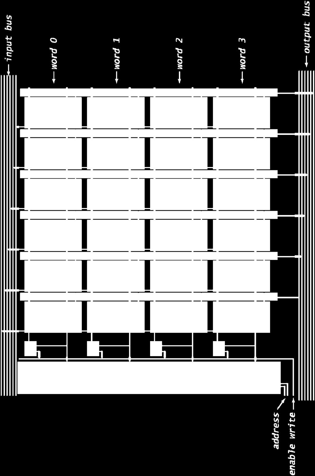
34 Memory bank. Memory Bank Bank of n registers; each stores k bits. Read and write information to one of n registers. Address inputs specify which one. log 2 n address bits needed Addressed bits always appear on output. If write enabled, k input bits are copied into addressed register. Ex 1. TOY main memory. 256-by-16 memory bank. Ex 2. TOY registers. 16-by-16 memory bank. Two output buses. (four 6-bit words) 6-bit input bus 2-bit address 6-bit output bus 34
")
35 Memory: Interface (four 6-bit words) 35

36 Memory: Component Level Implementation 36

37 Memory: Switch Level Implementation (four 6-bit words) 37
38 Summary Sequential circuits add "state" to digital hardware. Flip-flop. [represents 1 bit] TOY word. [16 flip-flops] TOY registers. [16 words] TOY main memory. [256 words] Modern technologies for registers and main memory are different. Few registers, easily accessible, high cost per bit. Huge main memories, less accessible, low cost per bit. Drastic evolution of technology over time. Next. Build a complete TOY computer. 38
39 The Clock tock tock tock tock clock signal tick tick tick tick cycle cycle cycle cycle In our jargon, a clock cycle = tick-phase (low), followed by a tock-phase (high) In real hardware, the clock is implemented by an oscillator In our hardware simulator, clock cycles can be simulated either Manually, by the user, or Automatically, by a test script.
40 Flip-flop in DFF out out(t) = in(t-1) A fundamental state-keeping device For now, let us not worry about the DFF implementation Memory devices are made from numerous flip-flops, all regulated by the same master clock signal Notational convention: in sequential chip out = (notation) in sequential chip out clock signal
41 1-bit register (we call it Bit ) Objective: build a storage unit that can: load (a) Change its state to a given input (b) Maintain its state over time (until changed) in Bit out if load(t-1) then out(t)=in(t-1) else out(t)=out(t-1) in DFF out in DFF out out(t) = in(t-1) Basic building block out(t) = out(t-1)? out(t) = in(t-1)? Won t work
42 Bit register (cont.) Interface load Implementation load in Bit out in MUX DFF out if load(t-1) then out(t)=in(t-1) else out(t)=out(t-1) o o o Load bit Read logic Write logic
43 Multi-bit register load load in Bit out in w Bit Bit... Bit w out if load(t-1) then out(t)=in(t-1) else out(t)=out(t-1) 1-bit register if load(t-1) then out(t)=in(t-1) else out(t)=out(t-1) w-bit register o o o Register s width: a trivial parameter Read logic Write logic
44 Aside: Hardware Simulation Relevant topics from the HW simulator tutorial: Clocked chips: When a clocked chip is loaded into the simulator, the clock icon is enabled, allowing clock control Built-in chips: feature a standard HDL interface yet a Java implementation Provide behavioral simulation services May feature GUI effects (at the simulator level only).
45 Random Access Memory (RAM) load register 0 register 1 in (word) register 2. register n-1 out (word) address (0 to n-1) RAM n Direct Access Logic o o Read logic Write logic.

46 RAM interface load in 16 bits address RAMn out 16 bits log 2 n bits
47 RAM anatomy RAM 64 RAM8 RAM 8. 8 Register register. register 8 RAM8 Bit Bit... Bit register... Recursive ascent
48 Counter Needed: a storage device that can: (a) set its state to some base value (b) increment the state in every clock cycle (c) maintain its state (stop incrementing) over clock cycles (d) reset its state inc load reset in w bits PC (counter) w bits out If reset(t-1) then out(t)=0 else if load(t-1) then out(t)=in(t-1) else if inc(t-1) then out(t)=out(t-1)+1 else out(t)=out(t-1) Typical function: program counter Implementation: register chip + some combinational logic.
49 Recap: Sequential VS combinational logic Combinational chip Sequential chip (optional) time delay (optional) in comb. logic out in comb. logic DFF gate(s) comb. logic out out = some function of (in) out(t) = some function of (in(t-1), out(t-1))
50 tock Time matters tock tock tock clock signal tick tick tick tick cycle cycle cycle cycle During a tick-tock cycle, the internal states of all the clocked chips are allowed to change, but their outputs are latched At the beginning of the next cycle, the outputs of all the clocked chips in the architecture commit to the new values. a Reg1 Implications: Challenge: propagation delays sel + out Solution: clock synchronization b Reg2 Cycle length and processing speed.
51 Perspective All the memory units described in this lecture are standard Typical memory hierarchy SRAM ( static ), typically used for the cache Access time Cost DRAM ( dynamic ), typically used for main memory Disk (Elaborate caching / paging algorithms) A Flip-flop can be built from Nand gates But... real memory units are highly optimized, using a great variety of storage technologies.
Chapter 3: Sequential Logic
 Elements of Computg Systems, Nisan & Schocken, MIT Press, 2005 www.idc.ac.il/tecs Chapter 3: Sequential Logic Usage and Copyright Notice: Copyright 2005 Noam Nisan and Shimon Schocken This presentation
6.3 Sequential Circuits (plus a few Combinational)
") 6.3 Sequential Circuits (plus a few Combinational) Logic Gates: Fundamental Building Blocks Introduction to Computer Science Robert Sedgewick and Kevin Wayne Copyright 2005 http://www.cs.princeton.edu/introcs
6.3 Sequential Circuits (plus a few Combinational) Logic Gates: Fundamental Building Blocks Introduction to Computer Science Robert Sedgewick and Kevin Wayne Copyright 2005 http://www.cs.princeton.edu/introcs
Sequential Logic. Sequential circuits. Reuse circuit elements by storing bits in "memory." Introduction to Computer Yung-Yu Chuang
 Sequential Lgic Intrductin t Cmputer Yung-Yu Chuang Review f Cmbatinal Circuits Cmbatinal circuits. Basic abstractin = switch. In prciple, can build TOY cmputer with a cmbatinal circuit. 255 6 = 4,8 puts
6.1 Combinational Circuits
 6. Combinational Circuits Digital signals Binar (or logical ) values: or, on or off, high or low voltage Wires. Propagate logical values from place to place. ignals "flow" from left to right. ignals and
CSE115: Digital Design Lecture 23: Latches & Flip-Flops
 Faculty of Engineering CSE115: Digital Design Lecture 23: Latches & Flip-Flops Sections 7.1-7.2 Suggested Reading A Generic Digital Processor Building Blocks for Digital Architectures INPUT - OUTPUT Interconnect:
COMP2611: Computer Organization. Introduction to Digital Logic
 1 COMP2611: Computer Organization Sequential Logic Time 2 Till now, we have essentially ignored the issue of time. We assume digital circuits: Perform their computations instantaneously Stateless: once
CS 261 Fall Mike Lam, Professor. Sequential Circuits
 CS 261 Fall 2018 Mike Lam, Professor Sequential Circuits Circuits Circuits are formed by linking gates (or other circuits) together Inputs and outputs Link output of one gate to input of another Some circuits
Combinational vs Sequential
 Combinational vs Sequential inputs X Combinational Circuits outputs Z A combinational circuit: At any time, outputs depends only on inputs Changing inputs changes outputs No regard for previous inputs
Computer Systems Architecture
 Computer Systems Architecture Fundamentals Of Digital Logic 1 Our Goal Understand Fundamentals and basics Concepts How computers work at the lowest level Avoid whenever possible Complexity Implementation
Logic Design. Flip Flops, Registers and Counters
 Logic Design Flip Flops, Registers and Counters Introduction Combinational circuits: value of each output depends only on the values of inputs Sequential Circuits: values of outputs depend on inputs and
Logic Design ( Part 3) Sequential Logic- Finite State Machines (Chapter 3)
 Sequential Logic- Finite State Machines (Chapter 3)") Logic esign ( Part ) Sequential Logic- Finite State Machines (Chapter ) Based on slides McGraw-Hill Additional material 00/00/006 Lewis/Martin Additional material 008 Roth Additional material 00 Taylor
Logic esign ( Part ) Sequential Logic- Finite State Machines (Chapter ) Based on slides McGraw-Hill Additional material 00/00/006 Lewis/Martin Additional material 008 Roth Additional material 00 Taylor
Read-only memory (ROM) Digital logic: ALUs Sequential logic circuits. Don't cares. Bus
 Digital logic: ALUs Sequential logic circuits. Don't cares. Bus") Digital logic: ALUs Sequential logic circuits CS207, Fall 2004 October 11, 13, and 15, 2004 1 Read-only memory (ROM) A form of memory Contents fixed when circuit is created n input lines for 2 n addressable
Digital logic: ALUs Sequential logic circuits CS207, Fall 2004 October 11, 13, and 15, 2004 1 Read-only memory (ROM) A form of memory Contents fixed when circuit is created n input lines for 2 n addressable
Last time, we saw how latches can be used as memory in a circuit
 Flip-Flops Last time, we saw how latches can be used as memory in a circuit Latches introduce new problems: We need to know when to enable a latch We also need to quickly disable a latch In other words,
Logic and Computer Design Fundamentals. Chapter 7. Registers and Counters
 Logic and Computer Design Fundamentals Chapter 7 Registers and Counters Registers Register a collection of binary storage elements In theory, a register is sequential logic which can be defined by a state
Chapter 6. Flip-Flops and Simple Flip-Flop Applications
 Chapter 6 Flip-Flops and Simple Flip-Flop Applications Basic bistable element It is a circuit having two stable conditions (states). It can be used to store binary symbols. J. C. Huang, 2004 Digital Logic
Advanced Devices. Registers Counters Multiplexers Decoders Adders. CSC258 Lecture Slides Steve Engels, 2006 Slide 1 of 20
 Advanced Devices Using a combination of gates and flip-flops, we can construct more sophisticated logical devices. These devices, while more complex, are still considered fundamental to basic logic design.
CS/ECE 250: Computer Architecture. Basics of Logic Design: ALU, Storage, Tristate. Benjamin Lee
 CS/ECE 25: Computer Architecture Basics of Logic esign: ALU, Storage, Tristate Benjamin Lee Slides based on those from Alvin Lebeck, aniel, Andrew Hilton, Amir Roth, Gershon Kedem Homework #3 ue Mar 7,
Objectives. Combinational logics Sequential logics Finite state machine Arithmetic circuits Datapath
 Objectives Combinational logics Sequential logics Finite state machine Arithmetic circuits Datapath In the previous chapters we have studied how to develop a specification from a given application, and
Sequential logic circuits
 Computer Mathematics Week 10 Sequential logic circuits College of Information Science and Engineering Ritsumeikan University last week combinational digital circuits signals and busses logic gates and,
Logic Design ( Part 3) Sequential Logic (Chapter 3)
 Sequential Logic (Chapter 3)") o Far: Combinational Logic Logic esign ( Part ) equential Logic (Chapter ) Based on slides McGraw-Hill Additional material 24/25/26 Lewis/Martin Additional material 28 oth Additional material 2 Taylor
o Far: Combinational Logic Logic esign ( Part ) equential Logic (Chapter ) Based on slides McGraw-Hill Additional material 24/25/26 Lewis/Martin Additional material 28 oth Additional material 2 Taylor
ELE2120 Digital Circuits and Systems. Tutorial Note 8
 ELE2120 Digital Circuits and Systems Tutorial Note 8 Outline 1. Register 2. Counters 3. Synchronous Counter 4. Asynchronous Counter 5. Sequential Circuit Design Overview 1. Register Applications: temporally
(CSC-3501) Lecture 7 (07 Feb 2008) Seung-Jong Park (Jay) CSC S.J. Park. Announcement
 Lecture 7 (07 Feb 2008) Seung-Jong Park (Jay) CSC S.J. Park. Announcement") Seung-Jong Park (Jay) http://www.csc.lsu.edu/~sjpark Computer Architecture (CSC-3501) Lecture 7 (07 Feb 2008) 1 Announcement 2 1 Combinational vs. Sequential Logic Combinational Logic Memoryless Outputs
Seung-Jong Park (Jay) http://www.csc.lsu.edu/~sjpark Computer Architecture (CSC-3501) Lecture 7 (07 Feb 2008) 1 Announcement 2 1 Combinational vs. Sequential Logic Combinational Logic Memoryless Outputs
Computer Science 324 Computer Architecture Mount Holyoke College Fall Topic Notes: Sequential Circuits
 Computer Science 324 Computer Architecture Mount Holyoke College Fall 2007 opic Notes: Sequential Circuits Let s think about how life can be bad for a circuit. Edge Detection Consider this one: What is
The word digital implies information in computers is represented by variables that take a limited number of discrete values.
 Class Overview Cover hardware operation of digital computers. First, consider the various digital components used in the organization and design. Second, go through the necessary steps to design a basic
DIGITAL SYSTEM FUNDAMENTALS (ECE421) DIGITAL ELECTRONICS FUNDAMENTAL (ECE422) LATCHES and FLIP-FLOPS
 DIGITAL ELECTRONICS FUNDAMENTAL (ECE422) LATCHES and FLIP-FLOPS") COURSE / CODE DIGITAL SYSTEM FUNDAMENTALS (ECE421) DIGITAL ELECTRONICS FUNDAMENTAL (ECE422) LATCHES and FLIP-FLOPS In the same way that logic gates are the building blocks of combinatorial circuits, latches
COURSE / CODE DIGITAL SYSTEM FUNDAMENTALS (ECE421) DIGITAL ELECTRONICS FUNDAMENTAL (ECE422) LATCHES and FLIP-FLOPS In the same way that logic gates are the building blocks of combinatorial circuits, latches
CS 110 Computer Architecture. Finite State Machines, Functional Units. Instructor: Sören Schwertfeger.
 CS 110 Computer Architecture Finite State Machines, Functional Units Instructor: Sören Schwertfeger http://shtech.org/courses/ca/ School of Information Science and Technology SIST ShanghaiTech University
Introduction to Sequential Circuits
 Introduction to Sequential Circuits COE 202 Digital Logic Design Dr. Muhamed Mudawar King Fahd University of Petroleum and Minerals Presentation Outline Introduction to Sequential Circuits Synchronous
Slide Set 7. for ENEL 353 Fall Steve Norman, PhD, PEng. Electrical & Computer Engineering Schulich School of Engineering University of Calgary
 Slide Set 7 for ENEL 353 Fall 216 Steve Norman, PhD, PEng Electrical & Computer Engineering Schulich School of Engineering University of Calgary Fall Term, 216 SN s ENEL 353 Fall 216 Slide Set 7 slide
Multiplexor (aka MUX) An example, yet VERY useful circuit!
 An example, yet VERY useful circuit!") Multiplexor (aka MUX) An example, yet VERY useful circuit! A B 0 1 Y S A B Y 0 0 x 0 0 1 x 1 1 x 0 0 1 x 1 1 S=1 S=0 Y = (S)? B:A; Y=S A+SB when S = 0: output A 1: output B 56 A 32-bit MUX Use 32 1-bit
Multiplexor (aka MUX) An example, yet VERY useful circuit! A B 0 1 Y S A B Y 0 0 x 0 0 1 x 1 1 x 0 0 1 x 1 1 S=1 S=0 Y = (S)? B:A; Y=S A+SB when S = 0: output A 1: output B 56 A 32-bit MUX Use 32 1-bit
CHAPTER1: Digital Logic Circuits
 CS224: Computer Organization S.KHABET CHAPTER1: Digital Logic Circuits 1 Sequential Circuits Introduction Composed of a combinational circuit to which the memory elements are connected to form a feedback
CS3350B Computer Architecture Winter 2015
 CS3350B Computer Architecture Winter 2015 Lecture 5.2: State Circuits: Circuits that Remember Marc Moreno Maza www.csd.uwo.ca/courses/cs3350b [Adapted from lectures on Computer Organization and Design,
Sequential Circuits: Latches & Flip-Flops
 Sequential Circuits: Latches & Flip-Flops Overview Storage Elements Latches SR, JK, D, and T Characteristic Tables, Characteristic Equations, Eecution Tables, and State Diagrams Standard Symbols Flip-Flops
CS61C : Machine Structures
 inst.eecs.berkeley.edu/~cs61c CS61C : Machine Structures Lecture 24 State Circuits : Circuits that Remember Senior Lecturer SOE Dan Garcia www.cs.berkeley.edu/~ddgarcia Bio NAND gate Researchers at Imperial
3. Sequential Logic 1
 Chapter 3: Sequential Logic 1 3. Sequential Logic 1 Time is the substance from which I am made. Time is a river which carries me along, but I am the river; it is a tiger that devours me, but I am the tiger;
Computer Science 324 Computer Architecture Mount Holyoke College Fall Topic Notes: Sequential Circuits
 Computer Science 324 Computer Architecture Mount Holyoke College Fall 2009 opic Notes: Sequential Circuits Let s think about how life can be bad for a circuit. Edge Detection Consider this one: What is
ECE 250 / CPS 250 Computer Architecture. Basics of Logic Design ALU and Storage Elements
 ECE 25 / CPS 25 Computer Architecture Basics of Logic esign ALU and Storage Elements Benjamin Lee Slides based on those from Andrew Hilton (uke), Alvy Lebeck (uke) Benjamin Lee (uke), and Amir Roth (Penn)
Logic Devices for Interfacing, The 8085 MPU Lecture 4
 Logic Devices for Interfacing, The 8085 MPU Lecture 4 1 Logic Devices for Interfacing Tri-State devices Buffer Bidirectional Buffer Decoder Encoder D Flip Flop :Latch and Clocked 2 Tri-state Logic Outputs
EMT 125 Digital Electronic Principles I CHAPTER 6 : FLIP-FLOP
 EMT 125 Digital Electronic Principles I CHAPTER 6 : FLIP-FLOP 1 Chapter Overview Latches Gated Latches Edge-triggered flip-flops Master-slave flip-flops Flip-flop operating characteristics Flip-flop applications
CHAPTER 4: Logic Circuits
 CHAPTER 4: Logic Circuits II. Sequential Circuits Combinational circuits o The outputs depend only on the current input values o It uses only logic gates, decoders, multiplexers, ALUs Sequential circuits
Figure 1 shows a simple implementation of a clock switch, using an AND-OR type multiplexer logic.
 1. CLOCK MUXING: With more and more multi-frequency clocks being used in today's chips, especially in the communications field, it is often necessary to switch the source of a clock line while the chip
Sequential logic. Circuits with feedback. How to control feedback? Sequential circuits. Timing methodologies. Basic registers
 equential logic equential circuits simple circuits with feedback latches edge-triggered flip-flops Timing methodologies cascading flip-flops for proper operation clock skew Basic registers shift registers
D Latch (Transparent Latch)
") D Latch (Transparent Latch) -One way to eliminate the undesirable condition of the indeterminate state in the SR latch is to ensure that inputs S and R are never equal to 1 at the same time. This is done
D Latch (Transparent Latch) -One way to eliminate the undesirable condition of the indeterminate state in the SR latch is to ensure that inputs S and R are never equal to 1 at the same time. This is done
Slide Set 6. for ENCM 369 Winter 2018 Section 01. Steve Norman, PhD, PEng
 Slide Set 6 for ENCM 369 Winter 2018 Section 01 Steve Norman, PhD, PEng Electrical & Computer Engineering Schulich School of Engineering University of Calgary February 2018 ENCM 369 Winter 2018 Section
Chapter 5 Sequential Circuits
 Logic and Computer Design Fundamentals Chapter 5 Sequential Circuits Part 2 Sequential Circuit Design Charles Kime & Thomas Kaminski 28 Pearson Education, Inc. (Hyperlinks are active in View Show mode)
VeriLab. An introductory lab for using Verilog in digital design (first draft) VeriLab
 VeriLab") VeriLab An introductory lab for using Verilog in digital design (first draft) VeriLab An introductory lab for using Verilog in digital design Verilog is a hardware description language useful for designing
VeriLab An introductory lab for using Verilog in digital design (first draft) VeriLab An introductory lab for using Verilog in digital design Verilog is a hardware description language useful for designing
CPS311 Lecture: Sequential Circuits
 CPS311 Lecture: Sequential Circuits Last revised August 4, 2015 Objectives: 1. To introduce asynchronous and synchronous flip-flops (latches and pulsetriggered, plus asynchronous preset/clear) 2. To introduce
Unit 11. Latches and Flip-Flops
 Unit 11 Latches and Flip-Flops 1 Combinational Circuits A combinational circuit consists of logic gates whose outputs, at any time, are determined by combining the values of the inputs. For n input variables,
CHAPTER 4: Logic Circuits
 CHAPTER 4: Logic Circuits II. Sequential Circuits Combinational circuits o The outputs depend only on the current input values o It uses only logic gates, decoders, multiplexers, ALUs Sequential circuits
211: Computer Architecture Summer 2016
 211: Computer Architecture Summer 2016 Liu Liu Topic: Storage Project3 Digital Logic - Digital Logic: Recap - Review: truth table => SOP => simplification - dual / complement - Minterm / Maxterm - SOP
ECE 341. Lecture # 2
 ECE 341 Lecture # 2 Instructor: Zeshan Chishti zeshan@pdx.edu October 1, 2014 Portland State University Announcements Course website reminder: http://www.ece.pdx.edu/~zeshan/ece341.htm Homework 1: Will
Contents Slide Set 6. Introduction to Chapter 7 of the textbook. Outline of Slide Set 6. An outline of the first part of Chapter 7
 CM 69 W4 Section Slide Set 6 slide 2/9 Contents Slide Set 6 for CM 69 Winter 24 Lecture Section Steve Norman, PhD, PEng Electrical & Computer Engineering Schulich School of Engineering University of Calgary
CSE140L: Components and Design Techniques for Digital Systems Lab. CPU design and PLDs. Tajana Simunic Rosing. Source: Vahid, Katz
 CSE140L: Components and Design Techniques for Digital Systems Lab CPU design and PLDs Tajana Simunic Rosing Source: Vahid, Katz 1 Lab #3 due Lab #4 CPU design Today: CPU design - lab overview PLDs Updates
ELCT201: DIGITAL LOGIC DESIGN
 ELCT201: DIGITAL LOGIC DESIGN Dr. Eng. Haitham Omran, haitham.omran@guc.edu.eg Dr. Eng. Wassim Alexan, wassim.joseph@guc.edu.eg Lecture 6 Following the slides of Dr. Ahmed H. Madian ذو الحجة 1438 ه Winter
Chapter 5 Synchronous Sequential Logic
 Chapter 5 Synchronous Sequential Logic Chih-Tsun Huang ( 黃稚存 ) http://nthucad.cs.nthu.edu.tw/~cthuang/ Department of Computer Science National Tsing Hua University Outline Introduction Storage Elements:
Sequencing. Lan-Da Van ( 范倫達 ), Ph. D. Department of Computer Science National Chiao Tung University Taiwan, R.O.C. Fall,
, Ph. D. Department of Computer Science National Chiao Tung University Taiwan, R.O.C. Fall,") Sequencing ( 范倫達 ), Ph. D. Department of Computer Science National Chiao Tung University Taiwan, R.O.C. Fall, 2013 ldvan@cs.nctu.edu.tw http://www.cs.nctu.edu.tw/~ldvan/ Outlines Introduction Sequencing
Sequencing ( 范倫達 ), Ph. D. Department of Computer Science National Chiao Tung University Taiwan, R.O.C. Fall, 2013 ldvan@cs.nctu.edu.tw http://www.cs.nctu.edu.tw/~ldvan/ Outlines Introduction Sequencing
cascading flip-flops for proper operation clock skew Hardware description languages and sequential logic
 equential logic equential circuits simple circuits with feedback latches edge-triggered flip-flops Timing methodologies cascading flip-flops for proper operation clock skew Basic registers shift registers
Logic Design II (17.342) Spring Lecture Outline
 Spring Lecture Outline") Logic Design II (17.342) Spring 2012 Lecture Outline Class # 03 February 09, 2012 Dohn Bowden 1 Today s Lecture Registers and Counters Chapter 12 2 Course Admin 3 Administrative Admin for tonight Syllabus
Logic Design II (17.342) Spring 2012 Lecture Outline Class # 03 February 09, 2012 Dohn Bowden 1 Today s Lecture Registers and Counters Chapter 12 2 Course Admin 3 Administrative Admin for tonight Syllabus
First Name Last Name November 10, 2009 CS-343 Exam 2
 CS-343 Exam 2 Instructions: For multiple choice questions, circle the letter of the one best choice unless the question explicitly states that it might have multiple correct answers. There is no penalty
Lecture 10: Sequential Circuits
 Introduction to CMOS VLSI esign Lecture 10: Sequential Circuits avid Harris Harvey Mudd College Spring 2004 1 Outline Floorplanning Sequencing Sequencing Element esign Max and Min-elay Clock Skew Time
CS 61C: Great Ideas in Computer Architecture
 CS 6C: Great Ideas in Computer Architecture Combinational and Sequential Logic, Boolean Algebra Instructor: Alan Christopher 7/23/24 Summer 24 -- Lecture #8 Review of Last Lecture OpenMP as simple parallel
COMP12111: Fundamentals of Computer Engineering
 COMP2: Fundamentals of Computer Engineering Part I Course Overview & Introduction to Logic Paul Nutter Introduction What is this course about? Computer hardware design o not electronics nothing nasty like
IS1500 (not part of IS1200) Logic Design Lab (LD-Lab)
 Logic Design Lab (LD-Lab)") Introduction IS1500 (not part of IS1200) Logic Design Lab (LD-Lab) 2017-10-26 The purpose of this lab is to give a hands-on experience of using gates and digital building blocks. These build blocks are
Introduction IS1500 (not part of IS1200) Logic Design Lab (LD-Lab) 2017-10-26 The purpose of this lab is to give a hands-on experience of using gates and digital building blocks. These build blocks are
MC9211 Computer Organization
 MC9211 Computer Organization Unit 2 : Combinational and Sequential Circuits Lesson2 : Sequential Circuits (KSB) (MCA) (2009-12/ODD) (2009-10/1 A&B) Coverage Lesson2 Outlines the formal procedures for the
Synchronous Sequential Logic
 Synchronous Sequential Logic -A Sequential Circuit consists of a combinational circuit to which storage elements are connected to form a feedback path. The storage elements are devices capable of storing
We are here. Assembly Language. Processors Arithmetic Logic Units. Finite State Machines. Circuits Gates. Transistors
 CSC258 Week 5 1 We are here Assembly Language Processors Arithmetic Logic Units Devices Finite State Machines Flip-flops Circuits Gates Transistors 2 Circuits using flip-flops Now that we know about flip-flops
COMP sequential logic 1 Jan. 25, 2016
 OMP 273 5 - sequential logic 1 Jan. 25, 2016 Sequential ircuits All of the circuits that I have discussed up to now are combinational digital circuits. For these circuits, each output is a logical combination
The outputs are formed by a combinational logic function of the inputs to the circuit or the values stored in the flip-flops (or both).
.") 1 The outputs are formed by a combinational logic function of the inputs to the circuit or the values stored in the flip-flops (or both). The value that is stored in a flip-flop when the clock pulse occurs
1 The outputs are formed by a combinational logic function of the inputs to the circuit or the values stored in the flip-flops (or both). The value that is stored in a flip-flop when the clock pulse occurs
More Digital Circuits
 More Digital Circuits 1 Signals and Waveforms: Showing Time & Grouping 2 Signals and Waveforms: Circuit Delay 2 3 4 5 3 10 0 1 5 13 4 6 3 Sample Debugging Waveform 4 Type of Circuits Synchronous Digital
CPE300: Digital System Architecture and Design
 CPE300: Digital System Architecture and Design Fall 2011 MW 17:30-18:45 CBC C316 1-Bus Architecture and Datapath 10262011 http://www.egr.unlv.edu/~b1morris/cpe300/ 2 Outline 1-Bus Microarchitecture and
Outline. EECS150 - Digital Design Lecture 27 - Asynchronous Sequential Circuits. Cross-coupled NOR gates. Asynchronous State Transition Diagram
 EECS150 - Digital Design Lecture 27 - Asynchronous Sequential Circuits Nov 26, 2002 John Wawrzynek Outline SR Latches and other storage elements Synchronizers Figures from Digital Design, John F. Wakerly
Chapter. Sequential Circuits
 Chapter Sequential Circuits Circuits Combinational circuit The output depends only on the input Sequential circuit Has a state The output depends not only on the input but also on the state the circuit
VARIABLE FREQUENCY CLOCKING HARDWARE
 VARIABLE FREQUENCY CLOCKING HARDWARE Variable-Frequency Clocking Hardware Many complex digital systems have components clocked at different frequencies Reason 1: to reduce power dissipation The active
Microprocessor Design
 Microprocessor Design Principles and Practices With VHDL Enoch O. Hwang Brooks / Cole 2004 To my wife and children Windy, Jonathan and Michelle Contents 1. Designing a Microprocessor... 2 1.1 Overview
EE 447/547 VLSI Design. Lecture 9: Sequential Circuits. VLSI Design EE 447/547 Sequential circuits 1
 EE 447/547 VLSI esign Lecture 9: Sequential Circuits Sequential circuits 1 Outline Floorplanning Sequencing Sequencing Element esign Max and Min-elay Clock Skew Time Borrowing Two-Phase Clocking Sequential
Chapter 4. Logic Design
 Chapter 4 Logic Design 4.1 Introduction. In previous Chapter we studied gates and combinational circuits, which made by gates (AND, OR, NOT etc.). That can be represented by circuit diagram, truth table
Latches, Flip-Flops, and Registers. Dr. Ouiem Bchir
 Latches, Flip-Flops, and Registers (Chapter #7) Dr. Ouiem Bchir The slides included herein were taken from the materials accompanying Fundamentals of Logic Design, 6 th Edition, by Roth and Kinney. Sequential
BUSES IN COMPUTER ARCHITECTURE
 BUSES IN COMPUTER ARCHITECTURE The processor, main memory, and I/O devices can be interconnected by means of a common bus whose primary function is to provide a communication path for the transfer of data.
NH 67, Karur Trichy Highways, Puliyur C.F, Karur District UNIT-III SEQUENTIAL CIRCUITS
 NH 67, Karur Trichy Highways, Puliyur C.F, 639 114 Karur District DEPARTMENT OF ELETRONICS AND COMMUNICATION ENGINEERING COURSE NOTES SUBJECT: DIGITAL ELECTRONICS CLASS: II YEAR ECE SUBJECT CODE: EC2203
Find the equivalent decimal value for the given value Other number system to decimal ( Sample)
") VELAMMAL COLLEGE OF ENGINEERING AND TECHNOLOGY, MADURAI 65 009 Department of Information Technology Model Exam-II-Question bank PART A (Answer for all Questions) (8 X = 6) K CO Marks Find the equivalent
VELAMMAL COLLEGE OF ENGINEERING AND TECHNOLOGY, MADURAI 65 009 Department of Information Technology Model Exam-II-Question bank PART A (Answer for all Questions) (8 X = 6) K CO Marks Find the equivalent
Experiment 8 Introduction to Latches and Flip-Flops and registers
 Experiment 8 Introduction to Latches and Flip-Flops and registers Introduction: The logic circuits that have been used until now were combinational logic circuits since the output of the device depends
SEQUENTIAL CIRCUITS THE RELAY CIRCUIT
 SEQUENTIAL CIRCUITS THE RELAY CIRCUIT This circuit is one big circle. The main switch is open and the flexible contact is closed. Note: A closed inverter (NOT gate) circuit performs the same function.
11. Sequential Elements
 11. Sequential Elements Jacob Abraham Department of Electrical and Computer Engineering The University of Texas at Austin VLSI Design Fall 2017 October 11, 2017 ECE Department, University of Texas at Austin
NH 67, Karur Trichy Highways, Puliyur C.F, Karur District DEPARTMENT OF INFORMATION TECHNOLOGY CS 2202 DIGITAL PRINCIPLES AND SYSTEM DESIGN
 NH 67, Karur Trichy Highways, Puliyur C.F, 639 114 Karur District DEPARTMENT OF INFORMATION TECHNOLOGY CS 2202 DIGITAL PRINCIPLES AND SYSTEM DESIGN UNIT 4 SYNCHRONOUS SEQUENTIAL LOGIC Sequential circuits
Chapter. Synchronous Sequential Circuits
 Chapter 5 Synchronous Sequential Circuits Logic Circuits- Review Logic Circuits 2 Combinational Circuits Consists of logic gates whose outputs are determined from the current combination of inputs. Performs
Clock Domain Crossing. Presented by Abramov B. 1
 Clock Domain Crossing Presented by Abramov B. 1 Register Transfer Logic Logic R E G I S T E R Transfer Logic R E G I S T E R Presented by Abramov B. 2 RTL (cont) An RTL circuit is a digital circuit composed
Contents Circuits... 1
 Contents Circuits... 1 Categories of Circuits... 1 Description of the operations of circuits... 2 Classification of Combinational Logic... 2 1. Adder... 3 2. Decoder:... 3 Memory Address Decoder... 5 Encoder...
A clock is a free-running signal with a cycle time. A clock may be either high or low, and alternates between the two states.
 Clocks A clock is a free-running signal with a cycle time. A clock may be either high or low, and alternates between the two states. 1 The length of time the clock is high before changing states is its
COE 202: Digital Logic Design Sequential Circuits Part 1. Dr. Ahmad Almulhem ahmadsm AT kfupm Phone: Office:
 COE 202: Digital Logic Design Sequential Circuits Part 1 Dr. Ahmad Almulhem Email: ahmadsm AT kfupm Phone: 860-7554 Office: 22-324 Objectives Sequential Circuits Memory Elements Latches Flip-Flops Combinational
ESE 570 STATIC SEQUENTIAL CMOS LOGIC CELLS. Kenneth R. Laker, University of Pennsylvania, updated 25Mar15
 ESE 570 STATIC SEQUENTIAL CMOS LOGIC CELLS 1 Classes of Logic Circuits two stable op. pts. Latch level triggered. Flip-Flop edge triggered. one stable op. pt. One-shot single pulse output no stable op.
Previous Lecture Sequential Circuits. Slide Summary of contents covered in this lecture. (Refer Slide Time: 01:55)
") Previous Lecture Sequential Circuits Digital VLSI System Design Prof. S. Srinivasan Department of Electrical Engineering Indian Institute of Technology, Madras Lecture No 7 Sequential Circuit Design Slide
Previous Lecture Sequential Circuits Digital VLSI System Design Prof. S. Srinivasan Department of Electrical Engineering Indian Institute of Technology, Madras Lecture No 7 Sequential Circuit Design Slide
Digital Logic Design Sequential Circuits. Dr. Basem ElHalawany
 Digital Logic Design Sequential Circuits Dr. Basem ElHalawany Combinational vs Sequential inputs X Combinational Circuits outputs Z A combinational circuit: At any time, outputs depends only on inputs
Go BEARS~ What are Machine Structures? Lecture #15 Intro to Synchronous Digital Systems, State Elements I C
 CS6C L5 Intro to SDS, State Elements I () inst.eecs.berkeley.edu/~cs6c CS6C : Machine Structures Lecture #5 Intro to Synchronous Digital Systems, State Elements I 28-7-6 Go BEARS~ Albert Chae, Instructor
ELCT201: DIGITAL LOGIC DESIGN
 ELCT201: DIGITAL LOGIC DESIGN Dr. Eng. Haitham Omran, haitham.omran@guc.edu.eg Dr. Eng. Wassim Alexan, wassim.joseph@guc.edu.eg Lecture 7 Following the slides of Dr. Ahmed H. Madian محرم 1439 ه Winter
Introduction to Microprocessor & Digital Logic
 ME262 Introduction to Microprocessor & Digital Logic (Sequential Logic) Summer 2 Sequential Logic Definition The output(s) of a sequential circuit depends d on the current and past states of the inputs,
L14: Quiz Information and Final Project Kickoff. L14: Spring 2004 Introductory Digital Systems Laboratory
 L14: Quiz Information and Final Project Kickoff 1 Quiz Quiz Review on Monday, March 29 by TAs 7:30 P.M. to 9:30 P.M. Room 34-101 Quiz will be Closed Book on March 31 st (during class time, Location, Walker
DIGITAL CIRCUIT LOGIC UNIT 11: SEQUENTIAL CIRCUITS (LATCHES AND FLIP-FLOPS)
") DIGITAL CIRCUIT LOGIC UNIT 11: SEQUENTIAL CIRCUITS (LATCHES AND FLIP-FLOPS) 1 iclicker Question 16 What should be the MUX inputs to implement the following function? (4 minutes) f A, B, C = m(0,2,5,6,7)
DIGITAL CIRCUIT LOGIC UNIT 11: SEQUENTIAL CIRCUITS (LATCHES AND FLIP-FLOPS) 1 iclicker Question 16 What should be the MUX inputs to implement the following function? (4 minutes) f A, B, C = m(0,2,5,6,7)
The basic logic gates are the inverter (or NOT gate), the AND gate, the OR gate and the exclusive-or gate (XOR). If you put an inverter in front of
, the AND gate, the OR gate and the exclusive-or gate (XOR). If you put an inverter in front of") 1 The basic logic gates are the inverter (or NOT gate), the AND gate, the OR gate and the exclusive-or gate (XOR). If you put an inverter in front of the AND gate, you get the NAND gate etc. 2 One of the
1 The basic logic gates are the inverter (or NOT gate), the AND gate, the OR gate and the exclusive-or gate (XOR). If you put an inverter in front of the AND gate, you get the NAND gate etc. 2 One of the
55:131 Introduction to VLSI Design Project #1 -- Fall 2009 Counter built from NAND gates, timing Due Date: Friday October 9, 2009.
 55:131 Introduction to VLSI Design Project #1 -- Fall 2009 Counter built from NAND gates, timing Due Date: Friday October 9, 2009 Introduction In this project we will create a transistor-level model of
Hardware Design I Chap. 5 Memory elements
 Hardware Design I Chap. 5 Memory elements E-mail: shimada@is.naist.jp Why memory is required? To hold data which will be processed with designed hardware (for storage) Main memory, cache, register, and
Chapter 6. sequential logic design. This is the beginning of the second part of this course, sequential logic.
 Chapter 6. sequential logic design This is the beginning of the second part of this course, sequential logic. equential logic equential circuits simple circuits with feedback latches edge-triggered flip-flops