User Manual. Version Revision A
|
|
|
- Shannon Clarke
- 6 years ago
- Views:
Transcription


1 User Manual Version Revision A
2 b
3 TOC TOC Welcome 1 Contacting High End Systems 2 Patents 6 Terms and Conditions and Warranty Information 7 Important Safety Information 8 Fixture Overview 9 Features 11 Safety Considerations 13 Warnings 14 General Guidelines 15 Installation Instructions 16 Dimensional Drawings 17 Mounting Orientations 18 Linking Fixtures 19 DMX Start Address 21 Fixture Control Board 22 Control Board Functions 25 Preset Programming and Playback 39 DMX Control Protocol 44 Error Codes 50 i i
4 This page intentionally left blank to ensure new chapters start on right (odd number) pages. ii
5 Welcome Notice High End Systems, 2017, All Rights Reserved Information and specifications in this document are subject to change without notice. High End Systems assumes no responsibility or liability for any errors or inaccuracies that may appear in this manual. Trademarks used in this text: High End Systems, Wholehog, and Lithopatterns, and intellaspot are registered trademarks. Internal Effects, the High End Systems globe logo and the Hog logo are trademarks of High End Systems, Inc. Belden is a registered trademark of Belden, Inc. Other trademarks and trade names may be used in this document to refer to either the entities claiming the marks and names or their products. High End Systems disclaims any proprietary interest in trademarks and trade names owned by others. 1
6 Contacting High End Systems Sales Department Customer Service World Wide Web High End Systems, Inc Gracy Farms Lane Austin, TX USA voice: fax: Toll Free: High End Systems, Inc Gracy Farms Lane Austin, TX USA voice: fax: toll free:
7 3
8 4
9 5
10 Patents NOTICE OF INTELLECTUAL PROPERTY RIGHTS For a listing of patents go to the web address: 6
11 Terms and Conditions and Warranty Information Complete Terms and Conditions and Warranty information can be found on the website com/pub/products/hes-warranty-information.pdf. 7

12 Important Safety Information Instructions pertaining to continued protection against fire, electric shock, and injury to persons are found throughout this manual. Please read all instructions prior to assembling, mounting, and operating this equipment. The following international caution and warning symbols appear in margins throughout this manual to highlight messages. 8
13 Fixture Overview 9
14 This page intentionally left blank to ensure new chapters start on right (odd number) pages. 10
15 Features Modular Construction, Fast Service Design Electronic Cooling System Control, Active Thermal Control Fan Modes- Normal / Continuous / Studio LED Type- 440W Bright White Engine LED Hours- 70% Luminous output, 50,000 hrs. Control Options- DMX 512 / RDM / Art-Net DMX Channels Pin DMX/RDM Connector Art-Net Connector PowerCON TRUE1 Connector Pan and tilt movement: 8 and 16 bit resolution, for smooth and precise motion Movement: Pan: 540 Movement: Tilt: 265 Max Speed Pan- 360 (seconds) Max Speed Tilt- 180 (seconds) Motorized focus Motorized Zoom - ~12-40 Strobe/shutter: High speed shutter, 0-13 Hz or random strobe Dimmer intensity from 0%~100% Zoom - ~11deg - 35deg linear zoom Step-less Iris, 5-100% linear change iris, pulse iris effect Control board with full color LCD graphic display and touch-keyboard Internal battery for display and config. Enables users to enter menu for setting start address and other functions. Display: Can be changed 180 reverse to fit for different installation position. 7 Position color wheel, plus open white. Two directional rainbow effects CMY & CTO Variable Color Mixing for Infinite Color Possibilities Rotation gobo: 6 interchangeable, rotating gobos plus open Static gobo: 7 interchangeable, with variable speed Gobo shake and Gobo Indexing Animation flame effect Frost effect Position memory, auto correction after unexpected movement Software-upload by optional accessory dongle via DMX line Pan and Tilt Locks Road Case Included (Single) 11
16 TECHNICAL SPECIFICATIONS Power supply: AC V~, 50/60Hz Power consumption: 700W Net weight: 30 KGS 12


17 Safety Considerations This device has left the factory in perfect condition. In order to maintain this condition and to ensure a safe operation, it is absolutely necessary for the user to follow the safety instructions and warning notes written in this user manual. Important: Damages caused by the disregard of this user manual are not subject to warranty. The dealer will not accept liability for any resulting defects or problems. 13
18 Warnings If the fixture has been exposed to temperature changes due to environmental changes, do not switch it on immediately. The condensation that could form could cause internal damage. Leave the fixture switched off until it has reached room temperature. This fixture falls under protection-class I. Therefore it is essential that the device be earthed. The electrical connection must carry out by a qualified person. Make sure that the available voltage is within stated range. Make sure the power cord is never crimped or damaged by a sharp edge. Replace cable immediately if damaged, this work must be done by an authorized dealer. Always disconnect from power, when the device is not in use or before cleaning it. Only handle the power cord by the plug. Never pull out the plug by tugging the power cord. Don't project the beam onto combustible substances, this could cause a safety hazard and/or start a fire. Please be aware that damages caused by modifications to the fixture will void warranty. Keep away from children and non-professionals. Maintenance should be performed by a qualified individual. There are no serviceable parts inside the device. The following points have to be considered when inspecting the fixture for maintenance: All screws for installing the devices or parts of the device have to be tightly connected and must not be corroded. Mechanically moved parts must not show any traces of wear and must not rotate freely without unbalance. The electric power supply cables must not show any damage, material fatigue or excessive dirt. 14
19 General Guidelines This device is a lighting effect for professional use on stages, theaters, or other professional installations, etc., the device was designed for indoor use only. This fixture is only allowed to be operated with the max alternating current (AC Voltage) which stated in the technical specifications printed on the fixture. Lighting effects are not designed for permanent operation. Operation breaks ensure that the device will perform longer without failure Do not shake the device. Avoid brute force when installing or operating the device. While choosing the installation-spot, please make sure that the device is not exposed to extreme heat, moisture or dust. Please don't project the beam onto combustible substances. The minimum distance between light-output from the projector and the illuminated surface must be more than 0.5 meter or 1.6 ft. If you use the quick-lock cam to hang this fixture, be sure to properly insert the fasteners in the quick lock holes correctly. Do not hang this fixture without a safety cable. Operate the device only after having familiarized with its functions. Do not permit operation by unqualified persons, damages can occur due to unprofessional operation. Please use the original packaging if the device is to be transported. For safety reasons, please be aware that all modifications on the device are forbidden. If this device will be operated in any way different to the one described in this manual, the product may suffer damages and the warranty becomes void. Furthermore, misuse may lead to short-circuit, burns, electric shock, lamp explosion, crash, and other damage to the fixture or persons. 15
20 Installation Instructions The installation must always be secured with a secondary safety attachment, e.g. an appropriate safety cable. Never stand directly below the device when mounting, removing or servicing the fixture. The operator has to make sure the safety and technical installations are approved by an expert before taking using this fixture in the field for the first time. Fixed installations must be inspected by a skilled person on a regular basis. Overhead mounting requires extensive experience, including amongst others calculating working load limits, installation material being used, and periodic safety inspection of all installation material and the device. If you lack these qualifications, do not attempt the installation yourself. Improper installation can result in serious bodily injury. Attachment Instructions. Attach the Omega clamp on the bracket by tighten the M12 bolt on the bracket to the hole in the middle of the bracket. Insert the quick-lock fasteners of the bracket into the respective holes on the bottom of the fixture. Tighten the quick-lock fasteners fully clockwise. Install the second Omega clamp. Attach the safety-cable through the holes on the bottom of the base. Attach to the trussing system or other safe fixation point. Be sure the safety is fully looped, the quick-link is attached and fully tighten Inspect for complete attachment before lifting over-head 16
21 Dimensional Drawings Dims listed are mm and (inches) 17
22 Mounting Orientations Be sure this fixture is kept at least 0.5m (1.6ft) away from any flammable materials (decoration etc.). Always use and install the supplied safety cable as a safety measure to prevent accidental damage and/or injury in the event the clamp is improperly installed or fails. Overhead mounting requires extensive experience, including amongst others calculating working load limits, a detailed knowledge of the installation materials being used, and periodic safety inspection. This safety inspection must cover all installation material, trussing, hardware and the fixture. If you lack these qualifications, do not attempt the installation yourself. Improper installation can result in sever injury and possible death if struck by a falling fixture. 18
23 Linking Fixtures The SolaSpot 1000 fixture operates on standard DMX512 link controlled by a DMX console. The number of fixtures on a link will be determined by the combined number of channels required by all the fixtures. A SolaSpot 1000 fixture requires a 39 channel footprint on a standard DMX512 link. Attach the fixture to the link using data-grade cable and 5-pin or 3-pin XLR cable connectors Cable Connectors The SolaSpot 1000 fixture accepts both 3-pin and 5-pin XLR cable connectors. Cabling must have a male XLR connector on one end of the cable and a female XLR connector on the other end. 19
 fixture on the DMX link.")
24 Connecting to the Link To link one or more fixtures to a DMX controller: Connect the male XLR connector of a DMX Data cable to the controller s DMX Data Out connector. Connect the Data cable s female XLR connector to the Data In connector of the first (or next) fixture on the DMX link. Continue linking the remaining fixtures connecting a cable from the Data Out connector of each fixture to the Data In connector of the next fixture on the link. DMX Termination For installations where the DMX cable has to run a long distance or is in an electrically noisy environment, a DMX terminator on the last fixture of the link prevents data reflection, which can corrupt the data communication on the link. Terminate the link by installing a 120 ohm, 1/4 watt (minimum) terminator in the fixture s Data Out (female) cable connector in the last fixture on each DMX link. 20
25 DMX Start Address All fixtures should be given a unique DMX starting address when using a DMX signal, so that the correct fixture responds to the correct control signals. This DMX start address is the channel number from which the fixture starts to listen to the digital control information sent out from the DMX controller. The setting of this start address is achieved by setting the correct number on the display located on the base of the device. You can set the same starting address for all fixtures or a group of fixtures, or make use different addresses for each fixture individually. If you set the same address, all the units will start to listen to the same control signal from the same channel number. In other words, changing the settings of one channel will affect all the fixtures simultaneously. If you set a different address, each unit will start to listen to the channel number you have set, based on the quantity of control channels of the unit. That means changing the settings of one channel will affect only the selected fixture. In the case of this fixture, which is a 39 channel fixture, you should set the starting address of the first unit to 1, the second unit to 40 (39+ 1), the third to 79(40+ 39), and so on. 21
26 Fixture Control Board The Control Board offers several features: you can simply set the starting address, run the pre-programmed program or make other changes. The main menu is accessed by pressing the [Mode / ESC] button until the display is visible. Browse through the menu by pressing the [UP] button,[down] button, [Left] button or [Right] button. Press the [Enter] button in order to select the desired menu. You can change the selection by pressing the directional buttons. ie. the [UP] button,[down] button, [Left] button or [Right] Confirm every selection by pressing the [Enter]. You can leave every mode by pressing the [Mode / Esc ]button. The functions provided are described in the following sections. The menu item will disappear after 10 seconds after the last key press. The functions provided are described in the following sections. 22
27 23
28 24
29 Control Board Functions Address With this function, you can adjust the desired DMX start address via the Control Board. 1.Access the main menu. 2.Tap the <Up/Down>button until Address is displayed. 3.Press ENTER, the display will show Address. 4.Tap the <Up/Down> button, the display will show A001~AXXX 5.Press ENTER to confirm or press <MODE/ESC> to return to the main menu Time Info Current Time With this function, you can display the running time from last power on. The display shows XXXX, XXXX stands for the number of hours. The counter is reset after power-off. Tap the <Up/Down>button until "Info is displayed. Press ENTER, the display will show Info.. Tap the <Up/Down>button until the display will show Time Info.. Press ENTER, the display will show Time Info.. 2.Press <Up/Down>, the display will show Current Time. 3.Press< ENTER>, the display will show Current Time. 4.The display will show XXXX (Hours) ; 5.Press <ENTER> to confirm or press <MODE/ESC> to return to the main menu. Total Run Time With this function, you can display the total running time of the fixture. The display shows XXXX, XXXX stands for the number of hours. Tap the <Up/Down>button until "Info is displayed. Press ENTER, the display will show Info.. Tap the <Up/Down>button until the display will show Time Info.. Press ENTER, the display will show Time Info.. 2.Press <Up/Down>, the display will show Ttl Life Hrs. 3.Press< ENTER>, the display will show Ttl Life Hrs. 4.The display will show XXXX (Hours) ; 5.Press <ENTER> to confirm or press <MODE/ESC> to return to the main menu. 25
30 Last Run Time With this function, you can display the last running time of the fixture. The display shows XXXX, XXXX stands for the number of hours. Tap the <Up/Down>button until "Info is displayed. Press ENTER, the display will show Info.. Tap the <Up/Down>button until the display will show Time Info.. Press ENTER, the display will show Time Info.. 2.Press <Up/Down>, the display will show Last Run Hrs. 3.Press< ENTER>, the display will show Last Run Hrs. 4.The display will show XXXX (Hours) ; 5.Press <ENTER> to confirm or press <MODE/ESC> to return to the main menu. LED Hrs With this function, you can display total running time of the LED. The display shows XXXX, XXXX stands for the number of hours. Tap the <Up/Down>button until "Info is displayed. Press ENTER, the display will show Info.. Tap the <Up/Down>button until the display will show Time Info.. Press ENTER, the display will show Time Info.. 2.Press <Up/Down>, the display will show LED Hours. 3.Press< ENTER>, the display will show LED Hours. 4.The display will show XXXX (Hours) ; 5.Press <ENTER> to confirm or press <MODE/ESC> to return to the main menu. Timer PIN With this function, you can display the timer password. The time password is 038. Tap the <Up/Down>button until "Info is displayed. Press ENTER, the display will show Info.. Tap the <Up/Down>button until the display will show Time Info.. Press ENTER, the display will show Time Info.. 2.Press <Up/Down>, the display will show Timer PIN. 3.Press< ENTER>, the display will show Timer PIN, the time password is Press <ENTER> to confirm or press <MODE/ESC> to return to the main menu. 26
31 Clr Last Run With this function, you can clear last run time of the fixture. The display shows OFF or ON, Press Enter to confirm. Tap the <Up/Down>button until "Info is displayed. Press ENTER, the display will show Info.. Tap the <Up/Down>button until the display will show Time Info.. Press ENTER, the display will show Time Info.. 2.Press <Up/Down>, the display will show Clr Last Run. 3.At Timer Password menu input a correct password, press< ENTER>, the display will show Clr Last Run, 4.The display will show OFF or ON. 5.Press <ENTER> to confirm or press <MODE/ESC> to return to the main menu. Timer PIN With this function, you can display the timer password. The time password is 038. Tap the <Up/Down>button until "Info is displayed. Press ENTER, the display will show Info.. Tap the <Up/Down>button until the display will show Time Info.. Press ENTER, the display will show Time Info.. 2.Press <Up/Down>, the display will show LED Time PIN. 3.Press< ENTER>, the display will show LED Time PIN, the time password is Press <ENTER> to confirm or press <MODE/ESC> to return to the main menu. Clean LED Time With this function, you can clear the running time of the LED engine (this should not be done unless an engine has been replaced) Tap the <Up/Down>button until "Info is displayed. Press ENTER, the display will show Info.. Tap the <Up/Down>button until the display will show Time Info.. Press ENTER, the display will show Time Info.. 2.Press <Up/Down>, the display will show Clean LED Time. 3.At Timer Password prompt, input a correct password, press< ENTER>, the display will show Clean LED Time, 4. The display will show "Off" or "On" 5.Press <ENTER> to confirm or press <MODE/ESC> to return to the main menu. 27
32 Value Displayed NONE With this function, you can choose to turn off display of DMX Control channel values. Tap the <Up/Down>button until Info is displayed. Press ENTER, the display will show Info. 2.Press <Up/Down>, the display will show Value Disp. 3.Press< ENTER>, the display will show Value Disp. 4.The display show None. 5.Press <ENTER> to confirm or press <MODE/ESC> to return to the main menu. ALL, PAN With this function you can display the DMX 512 value of each channel. If all is selected, the display will automatically show a channel that is changing. Tap the <Up/Down>button until Info is displayed. Press ENTER, the display will show Info. 2.Tap the <Up/Down>button until Value Disp is displayed. 3.Press ENTER, the display will show Value Disp. 4.Tap the <Up/Down> button, choose each channel. 5.Press ENTER to confirm or press <MODE/ESC> to return to the main menu. Head Temp. With this function you can display the temperature on the display board of the base (near CMY-filter) in Celsius. Tap the <Up/Down>button until Info is displayed. Press ENTER, the display will show Info. 2.Press <Up/Down>, the display will show Head Temp.. 3.Press< ENTER>, the display will show Head Temp.. 4.The display show XXX C/ F. 5.Press <ENTER> to confirm or press <MODE/ESC> to return to the main menu. Fan Speed With this function you can display the RPM of various fans inside the fixture. Tap the <Up/Down>button until Info is displayed. Press ENTER, the display will show Info. 2.Press <Up/Down>, the display will show Fan Speed.. 3.Press< ENTER>, the display will show Fan 1: xxx RPM", Fan 2: xxx RPM"... 4.Press <ENTER> to confirm or press <MODE/ESC> to return to the main menu. 28
33 Ethernet IP With this function, you can display the IP address of the fixture. Tap the <Up/Down>button until Info is displayed. Press ENTER, the display will show Info. 2.Press <Up/Down>, the display will show Ethernet IP. 3.Press< ENTER>, the display will show Ethernet IP. 4.The display show Ethernet IP xxx.xxx.xxx.xxx. 5.Press <ENTER> to confirm or press <MODE/ESC> to return to the main menu. Software Ver With this function, you can display the software version of the device. Tap the <Up/Down>button until Info is displayed. Press ENTER, the display will show Info. 2.Press <Up/Down>, the display will show Software Ver. 3.Press< ENTER>, the display will show Software Ver. 4.The display show Ver x.x. 5.Press <ENTER> to confirm or press <MODE/ESC> to return to the main menu. Set Status No DMX Mode With this function, when DMX is not connected, it runs automatic, closed, hold and music. The default is hold. Tap the <Up/Down>button until Set is displayed. Press ENTER, the display will show Set. Tap the <Up/Down>button until the display will show Status. Press ENTER, the display will show Status. 2.Press <Up/Down>, the display will show No DMX Mode. 3.Press< ENTER>, the display will show No DMX Mode. 4.The display show Hold, Press <Up/Down>, the display will show Close, Auto, Music. 5.Press <ENTER> to confirm or press <MODE/ESC> to return to the main menu. 29
34 Pan Reverse With this function you can reverse the Pan-movement. Tap the <Up/Down>button until Set is displayed. Press ENTER, the display will show Set. Tap the <Up/Down>button until the display will show Status. Press ENTER, the display will show Status. 2.Press <Up/Down>, the display will show Pan Reverse. 3.Press< ENTER>, the display will show Pan Reverse. 4.The display show OFF, Press <Up/Down>, the display will show ON. 5.Press <ENTER> to confirm or press <MODE/ESC> to return to the main menu. Tilt Reverse With this function you can reverse the Tilt-movement. Tap the <Up/Down>button until Set is displayed. Press ENTER, the display will show Set. Tap the <Up/Down>button until the display will show Status. Press ENTER, the display will show Status. 2.Press <Up/Down>, the display will show Tilt Reverse. 3.Press< ENTER>, the display will show Tilt Reverse. 4.The display show OFF, Press <Up/Down>, the display will show ON. 5.Press <ENTER> to confirm or press <MODE/ESC> to return to the main menu. Encoders With this function, you can change the feedback of the pan movement or tilt movement. Tap the <Up/Down>button until Set is displayed. Press ENTER, the display will show Set. Tap the <Up/Down>button until the display will show Status. Press ENTER, the display will show Status. 2.Press <Up/Down>, the display will show Encoders. 3.Press< ENTER>, the display will show Encoders. 4.The display show ON, Press <Up/Down>, the display will show OFF. 5.Press <ENTER> to confirm or press <MODE/ESC> to return to the main menu. 30
35 Pan/Tilt Spd With this function, you can select modes from 1 to 4. Tap the <Up/Down>button until Set is displayed. Press ENTER, the display will show Set. Tap the <Up/Down>button until the display will show Status. Press ENTER, the display will show Status. 2.Press <Up/Down>, the display will show Pan/Tilt Spd. 3.Press< ENTER>, the display will show Pan/Tilt Spd. 4.The display show Speed 1, Press <Up/Down>, the display will show Speed 2, Speed 3, Speed 4. 5.Press <ENTER> to confirm or press <MODE/ESC> to return to the main menu. Hibernation Standby mode The lamp and step motors will be power off if the fixture stay without DMX signal for 15 mins (Factory default). The fixture will Home once it receive DMX signal again. Tap the <Up/Down>button until Set is displayed. Press ENTER, the display will show Set. Tap the <Up/Down>button until the display will show Status. Press ENTER, the display will show Status. 2.Press <Up/Down>, the display will show Hibernation. 3.Press< ENTER>, the display will show Hibernation. 4.The display show 15M, Press <Up/Down>, the display will show 01M, 02M. 99M or OFF. 5.Press <ENTER> to confirm or press <MODE/ESC> to return to the main menu. Defogger With this function, you can select ON / OFF, or OnPwr. Tap the <Up/Down>button until Set is displayed. Press ENTER, the display will show Set. Tap the <Up/Down>button until the display will show Defogger. Press ENTER, the display will show Defogger. 2.Press <Up/Down>, the display will show Defog ON. 3.Press< ENTER>, the display will show Pan/Tilt Spd. 4.The display show Speed 1, Press <Up/Down>, the display will show Speed 2, Speed 3, Speed 4. 5.Press <ENTER> to confirm or press <MODE/ESC> to return to the main menu. 31
36 Select Input Tap the <Up/Down>button until Set is displayed. Press ENTER, the display will show Set. 2.Press <Up/Down>, the display will show Select Input. 3.Press< ENTER>, the display will show Select Input. 4.The display show DMX Only, Press <Up/Down>, the display will show Art-Net On IP02, Art-Net On IP10. 5.Press <ENTER> to confirm or press <MODE/ESC> to return to the main menu. Set Universe then tap the <Up/Down>button until Set is displayed. Press ENTER, the display will show Set. 2.Press <Up/Down>, the display will show Set Universe. 3.Press< ENTER>, the display will show Set Universe. 4.The display show 000~ Press <ENTER> to confirm or press <MODE/ESC> to return to the main menu. Service PIN Service PIN The Password for this function is 50. RDM PID To take advantage of the technical capabilities of the RDM system, each fixture must have a unique RDM PID, this unique identifying number is used by the controller to manage an individual fixture. There cannot be duplicate RDM PID on the same DMX cable run, this will result in a data collision, and the controller may or may not notify of this issue. Ensure that all fixtures have a unique RDM PID if RDM functionality is to be used. If DMX splitters are used and RDM control is to be used, these splitters must support RDM. The number and type of RDM parameters depend on the RDM controller being used. To Set the RDM PID Navigate to: Set -> Service Settings -> Service PIN Press <UP> button to select 050 and press <ENTER.> Navigate to RDM PID: Press the <UP> button to select unique ID s for each fixture and press <ENTER.> Disp.Setting Shutoff Time With this function you can shut off the color LCD display after 2 to 60 minutes. Turn the encoder in order to select the desired shut off time. The default is 2 minute. 32
37 Flip Display With this function you can rotate the display by 180. Tap the <Up/Down>button until Set is displayed. Press ENTER, the display will show Set. 2. Tap the <Up/Down>button until the display will show Disp.Setting. 3. Press ENTER, the display will show Disp.Setting. 2.Press <Up/Down>, the display will show Flip Display. 3.Press< ENTER>, the display will show Flip Display. 4.The display show OFF, Press <Up/Down>, the display will show ON. 5.Press <ENTER> to confirm or press <MODE/ESC> to return to the main menu. Key Lock With this function you can activate the automatic keylock status. If this function is activated, the keys will be locked automatically after exiting the edit mode for 15 seconds. keeping press the<mode/esc> key for 3seconds if you do not need this function. Tap the <Up/Down>button until Set is displayed. Press ENTER, the display will show Set. 2.Press <Up/Down>, the display will show Key Lock. 3.Press< ENTER>, the display will show Key Lock. 4.The display show ON, Press <Up/Down>, the display will show OFF. 5.Press <ENTER> to confirm or press <MODE/ESC> to return to the main menu. Temp. C/F With this function, Display the temperature for Celsius or Fahrenheit. Tap the <Up/Down>button until Set is displayed. Press ENTER, the display will show Set. 2.Press <Up/Down>, the display will show Temp. C/F. 3.Press< ENTER>, the display will show Temp. C/F. 4.The display show Celsius, Press <Up/Down>, the display will show Fahrenheit. 5.Press <ENTER> to confirm or press <MODE/ESC> to return to the main menu. 33
38 Reset Default With this function, you can reset all settings to factory default. Tap the <Up/Down>button until Set is displayed. Press ENTER, the display will show Set. 2.Press <Up/Down>, the display will show ResetDefault. 3.Press< ENTER>, the display will show ResetDefault. 4.The display show OFF, Press <Up/Down>, the display will show ON. (ON = Restore to Factory Default) 5.Press <ENTER> to confirm or press <MODE/ESC> to return to the main menu. Test Home With this function you can reset the fixture, and reset the Control Boards. You can select the different reset functions by choosing different items in the menu. Tap the <Up/Down>button until Test is displayed. Press ENTER, the display will show Test. 2.Tap the <Up/Down>button until the display will show Home. Press ENTER, the display will show Home. 3.The display show All, Press <Up/Down>, the display will show Pan&Tilt,"Colors", Shutter, Others. 4.Press <ENTER> to confirm or press <MODE/ESC> to return to the main menu. Test Channel With this function you can test each channel on its (correct) function. Tap the <Up/Down>button until Test is displayed. Press ENTER, the display will show Test. 2.Press <Up/Down>, the display will show Test Channel. 3.Press< ENTER>, the display will show Test Channel. 4.The display will show Pan Moving first channel, Press <Up/Down>, to choose another channel. 5.Press <ENTER> to confirm or press <MODE/ESC> to return to the main menu. Manual Ctrl. With this function, you can adjust the fixture more easily. All effects will be canceled, the shutter opens and the dimmer intensity will be set to 100 %. With the individual functions, you can focus the light on a flat surface (wall) and perform various fixture adjustments. Tap the <Up/Down>button until Test is displayed. Press ENTER, the display will show Test. 2.Press <Up/Down>, the display will show Manual Ctrl.. 3.Press< ENTER>, the display will show Manual Ctrl.. 4.The display show PAN=XXX. 5.Press <ENTER> to confirm or press <MODE/ESC> to return to the main menu. 34
39 Calibration With this function, you can calibrate and adjust the effect wheels to their correct positions. The password is 050. Tap the <Up/Down>button until Test is displayed. Press ENTER, the display will show Test. 2.Press <Up/Down>, the display will show Calibration. 3.Press< ENTER>, the display will show Calibration. 4.The display show Password=XXXX. 5.Press <ENTER> to confirm or press <MODE/ESC> to return to the main menu. Preset In this menu, user can select different channels list by different sequence: For example, after the user enter this manual, if select Auto Program = CH 22, means in this User s mode, the Dimmer is in Channel 16. PlayBack DMX Control To set the fixture to be controlled via DMX. Tap the <Up/Down>button until Preset is displayed. Press ENTER, the display will show Preset. Tap the <Up/Down>button until the display will show PlayBack. Press ENTER, the display will show PlayBack. 2.Tap the <Up/Down>button until DMX Control is displayed. 3.Press ENTER, the display will show DMX Control. 4.Tap the <Up/Down> button, choose each channel. 5.Press ENTER to confirm or press <MODE/ESC> to return to the main menu. Set To Slave With this function, you can define the device as slave. Tap the <Up/Down>button until Preset is displayed. Press ENTER, the display will show Preset. Tap the <Up/Down>button until the display will show PlayBack. Press ENTER, the display will show PlayBack. 2.Tap the <Up/Down>button until Set To Slave is displayed. 3.Press ENTER, the display will show Set To Slave. 4.Tap the <Up/Down> button, the display will show Slave1, Slave2, Slave3. 5.Press ENTER to confirm or press <MODE/ESC> to return to the main menu. 35
40 Auto Program With this function, you can run the internal program. You can select the desired program under Select program. You can set the number of steps under Edit program. You can edit the individual scenes under Edit scenes. With this function, you can run the individual scenes manually or automatically, with the adjusted Step-Time. Tap the <Up/Down>button until Preset is displayed. Press ENTER, the display will show Preset. Tap the <Up/Down>button until the display will show PlayBack. Press ENTER, the display will show PlayBack. 2.Tap the <Up/Down>button until Auto Program is displayed. 3.Press ENTER, the display will show Auto Program. 4.Tap the <Up/Down> button, the display will show Master1, Alone. 5.Press ENTER to confirm or press <MODE/ESC> to return to the main menu. Music Ctrl. With this function, you can run the internal program sound-controlled. then tap the <Up/Down>button until Preset is displayed. Press ENTER, the display will show Preset. Tap the <Up/Down>button until the display will show PlayBack. Press ENTER, the display will show PlayBack. 2.Tap the <Up/Down>button until Music Ctrl. is displayed. 3.Press <ENTER>, the display will show Music Ctrl.. 4.Tap the <Up/Down> button, the display will show Master, Alone. 5.Press <ENTER> to confirm or press <MODE/ESC> to return to the main menu. Select Prog. With this function, you can select the program for the Program Run. Edit Prog. With this function, you can edit the internal programs. Edit Scenes With this function, you can edit the scenes of the internal programs. Rec. Controller This fixture features an integrated DMX-recorder by which you can transmit the programmed scenes from your DMX-controller to the fixture. Adjust the desired scene numbers via the encoder (from to). When you call up the scenes at your controller, they will automatically be transmitted to the moving head. Example: A Master unit can send up to 3 different data groups to the Slave units, i.e. a Master unit can start 3 different Slave units, which run 3 different programs. The Master unit sends the 3 program parts in a continuous loop. 36
41 To start an Auto Program : 1. Slave-Setting: Select Function Mode by navigating with the arrow key. Press the Enter button to confirm. Select Set to slave by navigating with the arrow key. Press the Enter button to confirm. Select Slave 1, Slave 2 or Slave 3. Press the Enter button to confirm. Press the MODE/ESC button in order to return to the main menu. 2. Automatic Program Run Select Function Mode by navigating with the arrow key. Press the Enter button to confirm. Select Auto Program by navigating with the arrow key. Press the Enter button to confirm. Select Master or Alone. The selection "Alone" means Stand Alone-mode and "Master" that the device is defined as master. Press the Enter button to confirm. Press the MODE/ESC button in order to return to the main menu. 3. Program selection for Auto Pro Part Select Edit program by navigating with the arrow key. Press the Enter button to confirm. Select Select programs by navigating with the arrow key. Press the Enter button to confirm. Select Auto Pro Part 1, Auto Pro Part 2 or Auto Pro Part 3, and then select which Slave program is to be sent. Selection Part 1 means, that the Slave unit runs the same program as the master units. Press the Enter button to confirm. Press the MODE/ESC button in order to return to the main menu. 4. Program selection for Edit Program Select Edit program by navigating with the arrow key. Press the Enter button to confirm. Select Edit program by navigating with the arrow key. Press the Enter button to confirm. Select the desired program. With this function you can edit specific scenes into a specific program. Press the Enter button to confirm. Press the MODE/ESC button in order to return to the main menu. 37
42 5. Automatic Scene Recording Select Edit program by navigating with the arrow key. Press the Enter button to confirm. Select Edit scenes by navigating with the arrow key. Select the desired scene numbers. You can program a maximum number of 250 Press the Enter button to confirm. Press the MODE/ESC button in order to return to the main menu. Example: Program 2 includes scenes: 10, 11, 12, 13 Program 4 includes scenes: 8, 9, 10 Program 6 includes scenes: 12, 13, 14, 15 Auto Pro Part 1 is Program 2; Auto Pro Part 2 is Program 4; Auto Pro Part 3 is Program 6 The 3 Slave groups run the Auto Program in certain time segments, as shown in the following picture: 38
43 Preset Programming and Playback SolaSpot 1000 fixtures can be programmed through the on board menu system using Preset Programming. This section describes how to program your fixtures for stand-alone operation using the on-board memory in each fixture to create and store scenes. Preset Programming Overview Presets are built from combining scenes into programs and then assigning the programs to Program Partitions for playback by a fixture designated as the Master and, if desired, groups of slave fixtures assigned to a Program Partition. SolaSpot 1000 fixtures ship with factory programmed scenes and programs ready for you to use or edit. Creating presets consists of performing the following steps: Designating a fixture as the Master Selecting/Editing Scenes Sequencing Scenes into Programs Sequencing Programs into Program Partitions Configuring slave fixtures on the link to playback a Program Partition from the master Navigating to the Preset Menu To enter the Preset Menu: Press the [MODE/ESC] button to enter the first level of the menu system. The display will show Address and Info as the first two options in the top menu level. The red star [*] indicates the current menu. Using the [UP],[DOWN] buttons, scroll to Preset. Press the [Enter] button to select. Master and Slave The following example shows the relationship between scenes, programs and partitions programmed on the Master and how slave groups are assigned. Groups of scenes are edited into Programs 1 6 on the fixture designated as Master Program 2 is assigned to Part 1 Program 4 is assigned to Part 2 Program 6 is assigned to Part 3 Fixtures assigned as Slave 1 playback Part 1 Fixtures assigned as Slave 2 playback Part 2 Fixtures assigned as Slave 3 playback Part 3 Scene 4 Scene 5 Scene 6 Scene 7 39
44 Preset Menu Playback Settings Preset programming requires one fixture to act as the Master. All other SolaSpot 1000 fixtures on the link can then be set as laves to playback the Master presets. Slave fixtures receive all their preset parameter and timing information from the master fixture. Playback settings designate a fixture as a master or a slave and also allow you to revert from Auto Programming to DMX control from console or set a fixture in Master or standalone mode for audio control. Automatic Program Run This Playback option lets you designate a fixture to playback in Standalone mode or as a Master. Alone is the default setting. To designate a fixture as a Master: Navigate to and select the Preset menu. Use the[up],[down] buttons to scroll to Playback menu and press [Enter]to select. 40
45 Use the[up],[down] buttons to scroll to Auto Program menu and press [Enter]to select. Use the [UP],[DOWN]buttons to scroll to Master and press [Enter]to select. Your choice will be shown in the display. Set to Slave After a preset program is defined on a Master fixture, other SolaSpot 1000 fixtures on the same DMX link can be designated laves to playback Program Part 1, 2 or 3 as defined on the Master fixture. To designate a fixture as a Slave: Navigate to and select the Preset menu. Use the [UP],[DOWN]buttons to scroll to Playback menu and press [Enter]to select. Use the [UP],[DOWN]buttons to scroll to Set To Slave menu and press [Enter]to select. Use the [UP],[DOWN]buttons to scroll to Slave1, Slave2, or Slave3 option and press [Enter]to select. Your choice will be shown in the display. DMX Control Selecting this option reverts the function from Auto Program (Preset Programming) to DMX Receive (console control). Selecting this option will take you back to the menu startup screen where DMX Receive will be displayed as the currently selected function. Music Control This Playback option lets you designate a fixture to playback scenes based on audio triggers detected by the internal microphone in stand alone or as a Master. Alone is the default setting. Edit Scenes A parameter is a fixture attribute that can be controlled to modify the light beam in terms of color, beam quality and pattern, intensity, or focus (position). DMX programming assigns a DMX value to each of the fixture s parameters. A scene is one combination of parameter settings. SolaSpot 1000 fixtures provide 250 pre-programmed scenes you can use or edit to build a preset program. The first 64 scenes ave factory created settings which can be edited as desired. Edit Scene Parameters The Edit Scenes option lets you select a DMX value for any of the 39 parameters in the SolaSpot 1000 DMX protocol. To edit the DMX parameters in a scene: Navigate to and select the Preset menu as shown on page 35. Use the [UP],[DOWN]buttons to scroll to the Edit Scenes option and press [Enter]to select. Use the [UP],[DOWN]buttons to scroll to the Scene number you wish to build on from and press to [Enter]select. Use the [UP],[DOWN]buttons to scroll to the parameter you wish to edit (Pan, Tilt, MSpeed, Color Wheel, etc.) and press to [Enter]select. Use the [UP],[DOWN]buttons to scroll to a new DMX value for the parameter you have selected and press[enter] to select. This takes you back to parameter options. Continue through all parameters until your desired look is complete. When you are finished selecting all parameter values for a particular Scene, press the [MODE/ESC]button to return to the Preset level menu. 41
46 Edit Scene Time This Scene Edit option lets you set the scene time in seconds from 00.2s 99.9s. The default value is 00.3s. This values determines how long the scene will play before the next scene is triggered. Set Fade Time This Scene Edit option lets you set a fade time value from This values determines the crossfade time applied to parameters once the scene is triggered. Set Input by Out This Scene Edit option allows you to capture the parameter values for a scene from DMX input into the fixture. Once you create a look from a DMX console do the following: Navigate to and select the Preset menu as shown on page 35. Use the [UP],[DOWN]buttons to scroll to the Edit Scenes option and press [Enter]to select. Use the [UP],[DOWN]buttons to scroll to the Scene number you wish to build on from and press to [Enter]select. Use the [UP],[DOWN]button to scroll to the Input by Out and [Enter]press to select. The scene will record the current parameter values being input via DMX. When you are finished capturing DMX into a scene, press [Enter]to return to the main menu. Edit Program This preset menu option lets you select from 10 factory set programs to edit. You can set up to 64 Scenes in a sequence of Steps for each program. You can also test the program at any time by selecting Program Test to playback the program as it is currently defined. To edit a program: Navigate to and select the Preset menu. Use the [UP],[DOWN] buttons to scroll to Edit Prog. menu and press [Enter]to select. Use the [UP],[DOWN] buttons to scroll to a program from Program 1 Program 10 and press [Enter]to select. Use the [UP],[DOWN]buttons to scroll to the Step in the program you want to edit from Step 1 to Step 64 and press [Enter]to select. The display will show which scene is currently assigned to that step. Use the [UP],[DOWN]buttons to scroll to the scroll to the scene you want to assign to the step and press [Enter]to select. When you have assigned all the steps you want, select End and press [Enter]to save the program. Select Program This preset option lets you assign a Preset Program to one of three Program Partitions. A fixture assigned as a Slave can playback any Program Partition defined by the Master fixture. Note: The Master fixture can only playback Program Partition 1 To assign a program to each Program Partition: Navigate to and select the Preset menu as shown on page 35. Use the [UP],[DOWN]buttons to scroll to Select Prog menu and press [Enter]to select. Each Program Part, has 10 preset programs. Use the [UP],[DOWN]buttons to scroll to Prog. Part 1 and press [Enter]to select. Use the [UP],[DOWN]buttons to scroll to a program from Program 1 Program 10 and press [Enter]to select the program you want to include in the Program Part. 42
47 Use the [UP],[DOWN]buttons to scroll to Prog. Part 2 and press [Enter]to select. Use the [UP],[DOWN]buttons to scroll to a program from Program 1 Program 10 and press[enter] to select the program you want to include in the Program Part. Use the [UP],[DOWN]buttons to scroll to Prog. Part 3 and press [Enter]to select. Use the [UP],[DOWN]buttons to scroll to a program from Program 1 Program 10 and press [Enter]to select the program you want to include in the Program Part. Press the [Mode / ESC] button to return to the main menu. Scenes Input This function allows you to capture multiple scenes from DMX values input to the fixture. You first define the number of scenes to capture and then each time a DMX value changes, a different scene will be captured. 1.Navigate to and select the Preset menu. 2.Use the buttons to scroll to the Scenes Input option and press to select. 3.Use the buttons to set the starting scene number. 4.Use the buttons to set the ending scene number. With each change of any DMX value, the capturing scene will advance to the next one in the range. 5.When all scenes have been recorded, the scenes input menu will automatically exit. Note: During Scenes Input recording, the SolaSpot 1000 does not playback the DMX input, it only captures it. You must edit or playback the scenes after recording to see the results. It is best to prepare the scenes on a DMX controller with a zero crossfade for all parameters between each step. Remember any change of a DMX value will advance to the next scene to capture. 43

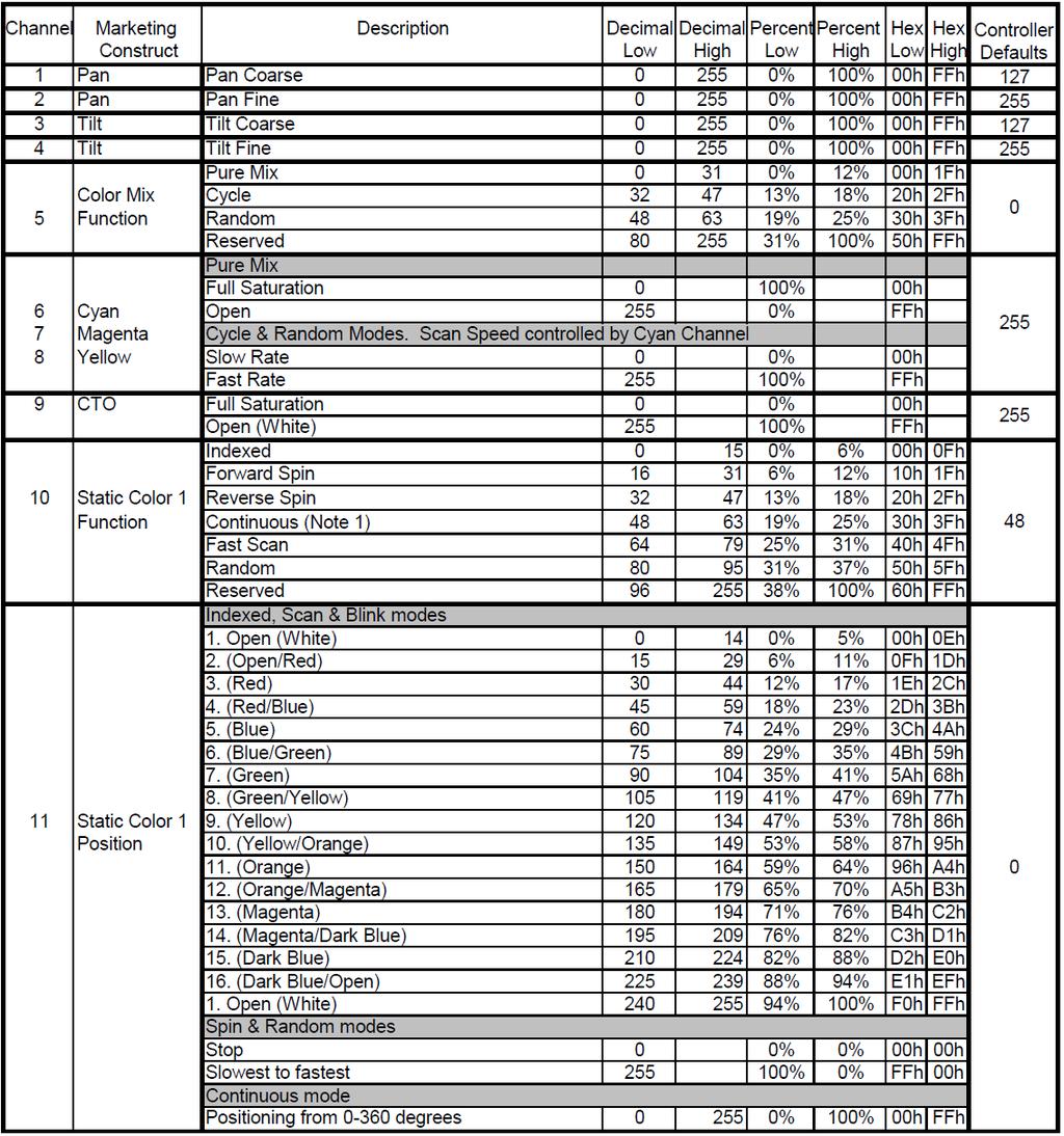
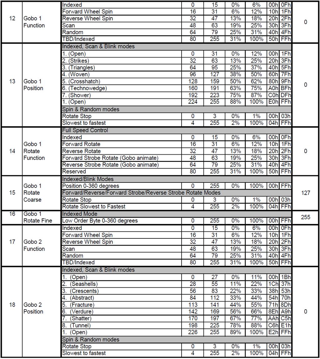
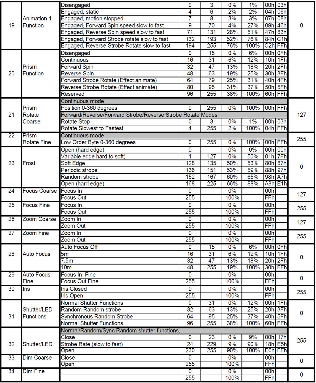
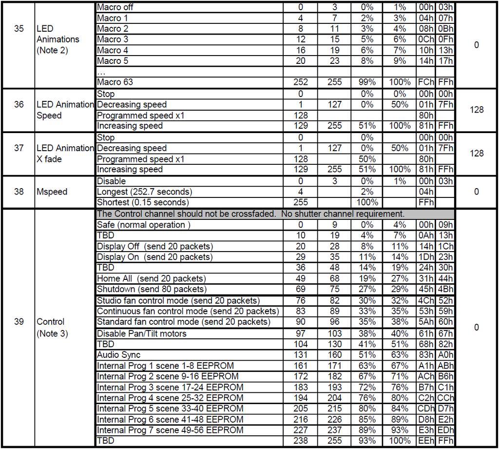
48 DMX Control Protocol The most current DMX Control Protocol data for the SolaSpot 1000 can be found on the High End Systems, Inc. website The following data is current as of protocol version 1.3, revision date July 13,
49 45
50 46
51 47
52 48

53 Protocol Notes 1. Continuous mode should take quickest path from 255-0, and Continuous mode color wheel aperture centers Discrete multi step LED animations to be defined later. These will require macro speed and x fade channels. The macros will operate independently. The Xfade and speed channels act as multipliers of the programmed speed in the discrete macro steps. Speed / X fade channel operation 0 stops playback or crossfade decreases playback speed / crossfade time (* <1) 128 playback or cross fade speed is as programmed (*1) increases playback speed / crossfade time (* >1) 3. Fan control modes are not retentive. When the fixture is turned off it will default back to Standard mode. 49
54 Error Codes When you turn on the fixture, it will complete a start-up procedure. The display may show Err channel is XX if there are problems with one or more channels. XX stands for channel 1, 2, 3, 4, 5, 6 - testing positioning sensors. For example, when the display shows Err channel is Color wheel, it means there is an error in channel 13. If there are errors on channel 1, channel 3, channel 7 at the same time, you may see the error message Err channel is Pan movement, Err channel is Tilt movement, Err channel is Dimmer flash repeated for 2 times, and then the fixture will generate a second reset. If the fixture error message is retained after performing reset more than 2 times, only the channels which have errors will not work properly, others can work. Please contact support if detailed assistance is needed. PAN- Er (PAN-yoke movement error) This message will appear after the reset of the fixture if the yoke s magnetic-indexing circuit malfunction (sensor failed or magnet missing) or the stepping-motor is defective (or its driving IC on the main PCB). The PAN- movement is not located in the default position after the reset. TILT- Er (TILT-head movement error) This message will appear after the reset of the fixture if the head s magnetic-indexing circuit malfunctions (sensor failed or magnet missing) or the stepping-motor is defective (or its driving IC on the main PCB). The TILT- movement is not located in the default position after the reset. Gobo Wheel 1 Er (Gobo Wheel 1- error) This message will appear after the reset of the fixture if the magnetic-indexing circuit malfunction (sensor failed or magnet missing) or the stepping-motor is defective (or its driving IC on the main PCB). The Gobo Wheel 1 is not located in the default position after the reset. Gobo Rot. 1 Er (Gobo Rot. 1- error) This message will appear after the reset of the fixture if the magnetic-indexing circuit malfunction (sensor failed or magnet missing) or the stepping-motor is defective (or its driving IC on the main PCB). The Gobo Rot. 1 is not located in the default position after the reset. Gobo Wheel 2 Er (Gobo Wheel 2- error) This message will appear after the reset of the fixture if the magnetic-indexing circuit malfunction (sensor failed or magnet missing) or the stepping-motor is defective (or its driving IC on the main PCB). The Gobo Wheel 2 is not located in the default position after the reset. Focus Er (Focus - error) This message will appear after the reset of the fixture if the magnetic-indexing circuit malfunction (sensor failed or magnet missing) or the stepping-motor is defective (or its driving IC on the main PCB). The Focus is not located in the default position after the reset. Zoom Er (Zoom wheel error) This message will appear after the reset of the fixture if the head s magnetic-indexing circuit malfunctions (sensor failed or magnet missing) or the stepping-motor is defective (or its driving IC on the main PCB). The Zoom - wheel is not located in the default position after the reset. Animation Er 50
User Manual. Version Revision A
 User Manual Version 1.11 --- Revision A b Contents Contents Welcome 1 Contacting High End Systems 2 Patents 6 Terms and Conditions and Warranty Information 7 Important Safety Information 9 Fixture Overview
User Manual. Version Revision A
 User Manual Version 1.2 --- Revision A . b Contents Contents Welcome 3 Contacting High End Systems 4 Patents 8 Terms and Conditions and Warranty Information 9 Important Safety Information 10 Fixture Overview
User Manual. Version Revision A
 User Manual Version 1.2 --- Revision A SolaFrame 2000 v1.2 2 User Manual Contents Welcome...5 Contacting High End Systems...6 Declaration of Conformity...7 FCC Information...9 Patent information... 10
User Manual. Version 1.0.1
 User Manual Version 1.0.1 Table of Contents Welcome...3 Contacting High End Systems...4 Patents......7 Warranty Information......9 Important Safety Information......10 Fixture Overview.........11 Features......12
USER MANUAL. Version Revision A
 USER MANUAL Version 1.3 -- Revision A SolaHyBeam 2000 User Manual 2 v1.3 Contents Welcome 5 KEEP THIS MANUAL FOR FUTURE NEEDS 5 Contacting High End Systems 6 Patent information 9 FCC Information 10 Terms
Professional Moving Head User Manual
 Professional Moving Head User Manual Version 1.2.3 --- Revision A SolaFrame Theatre v1.2.3 2 User Manual Contents Declaration of Conformity... 7 Patent information... 9 Production Modification Warning...
LED Thunder S-150 Code 1097
 LED Thunder S-150 Code 1097 User Manual 1 1 SAFETY INSTRUCTIONS This device has left the factory in perfect condition. In order to maintain this condition and to ensure a safe operation, it is absolutely
LED Spot 300W. Please read this user manual before your operation
 LED Spot 300W Please read this user manual before your operation 1. Introduction 2. General Guideline 3. Safety Instructions 4. Cleaning and Maintenance 5. Technical Parameters 6. DMX Channels 7. Remark
Contents. Classe LS 200 v1.0
 Contents 1. Features... - 2-2. FIXTURE OVERVIEW... - 3-3. SAFETY INSTRUCTIONS... - 4-3.1) Important safety warns... - 4-3.2) GENERAL GUIDELINES... - 5-4. INSTALLATION INSTRUCTIONS... - 5-4.1) Mounting
User Manual. 360W LED Moving Zoom KEEP THIS MANUAL FOR FUTURE NEEDS. 36pcs10W 4 in 1 RGBW LEDs
 User Manual 360W LED Moving Zoom 36pcs10W 4 in 1 RGBW LEDs KEEP THIS MANUAL FOR FUTURE NEEDS 1. Dispacking Thank you for choosing our moving head. For your own safety, please read this manual before installing
Fixture One XLR Signal Cable One Omega Clamp - Two Safety Chain One User Manual - One
 TABLE OF CONTENTS 1. INTRODUCTION AND UNPACKING 1 2. SAFTEY INSTRUCTIONS 1-2 3. OPERATION INSTRUCTIONS 2-3 4. MOUNTING AND INSTALLATION 3-4 5. DMX-512 CONTROL CONNECTIONS 4-5 6. MENU NAVIGATION 5 7. PHOTOMETRIC
This device is a lighting effect for professional use on stages, in discotheques, theatres, etc..
 At first, thank you for purchasing QUADRO 24. For the sake of safety and regular operation of this projector, please read this manual carefully before using and operating it, lest incur any personal injury
LED Beam Moving Head. TWIST-150LED Order No INSTRUCTION MANUAL
 LED Beam Moving Head TWIST-150LED Order No. 38.7970 INSTRUCTION MANUAL MONACOR INTERNATIONAL GmbH & Co. KG Zum Falsch 36 28307 Bremen Germany www.monacor.com 01.30.11.2016 ELECTRONICS FOR SPECIALISTS ELECTRONICS
KEEP THIS MANUAL FOR FUTURE NEEDS
 USER MANUAL KEEP THIS MANUAL FOR FUTURE NEEDS Contents 1. Features... 2 2. Fixture Overview... 3 3. SAFETY INSTRUCTIONS... 3 3.1) Important safety warns... 3 3.2) GENERAL GUIDELINES... 4 4. INSTALLATION
KEEP THIS MANUAL FOR FUTURE NEEDS
 USER S MANUAL www.lfxgroup.com MOVING HEAD PRO HEAD 250 KEEP THIS MANUAL FOR FUTURE NEEDS For your own safety, please read this user manual carefully before installing the device. Keep this device away
User Manual. Version 0.0.1
 User Manual Version 0.0.1 Contents Contacting High End Systems... 5 Declaration of Conformity... 6 Patent information... 8 Warranty Information... 8 Production Modification Warning... 9 Important Safety
ALO 030 MKII. 30 Watt DMX LED scanner. User manual
 ALO 030 MKII 30 Watt DMX LED scanner User manual Safety instructions WARNING! Always keep this device away from moisture and rain! Hazardous electrical shocks may occur! WARNING! Only connect this device
PLATINUM BEAM 5R KEEP THIS MANUAL FOR FUTURE NEEDS
 PLATINUM BEAM 5R KEEP THIS MANUAL FOR FUTURE NEEDS 2 Thank you for your patronage. We are confident that our excellent products and service can satisfy you. For your own safety, please read this user
LED SPOT HEAD USERS GUIDE
 LED SPOT HEAD USERS GUIDE 1. Product Introduction: 1 1.1 Before unpack the fixture, pls make sure that the packing is in good condition, following items will be found in the box: -The fixture -This users
BSL HELIOS USERS GUIDE
 BSL HELIOS USERS GUIDE 1. Product Introduction: 1.1 Before unpack the fixture, pls make sure that the packing is in good condition, following items will be found in the box: - The fixture - This users
USER MANUAL. DE-1 Police-light. CAUTION! Keep this device away from rain and moisture! Unplug mains lead before opening the housing!
 USER MANUAL DE-1 Police-light CAUTION! Keep this device away from rain and moisture! Unplug mains lead before opening the housing! For your own safety, please read this user manual carefully before you
SATURA PROFILE. user manual. ELATION SATURA PROFILE user manual
 SATURA PROFILE user manual ELATION SATURA PROFILE user manual 2016 ELATION PROFESSIONAL all rights reserved. Information, specifications, diagrams, images, and instructions herein are subject to change
AuraBeam 150 LED. User Manual KEEP THIS MANUAL FOR FUTURE NEEDS
 AuraBeam 150 LED LED 0.2m ta 40 C tc 150 C User Manual KEEP THIS MANUAL FOR FUTURE NEEDS 1 SAFETY INSTRUCTIONS CAUTION Becareful with your operations.with a dangerous voltage you cansuffer a dangerous
PLATINUM SPOT III. user manual. ELATION PLATINUM SPOT III user manual
 PLATINUM SPOT III user manual ELATION PLATINUM SPOT III user manual 2015 ELATION PROFESSIONAL all rights reserved. Information, specifications, diagrams, images, and instructions herein are subject to
ElektraLite lightstream
 ElektraLite lightstream USER MANUAL (Version 1.02) Elektralite (a division of Group One), 70, Sea Lane, Farmingdale, NY11735, U.S.A. T. +1 (631)-396-0184. F. +1 (631)-396-0190 WWW.MYELEKTRALITE.COM 1.
Contens. Classe LWZ 40 v1.0
 Contens 1. Features... 2 2. Fixture Overview... 3 3. SAFETY INSTRUCTIONS... 3 3.1) Important safety warns... 3 3.2) GENERAL GUIDELINES... 4 4. INSTALLATION INSTRUCTIONS... 5 4.1) Mounting the device...
PROFESSIONAL MOVING HEAD USER S MANUAL DESIGN WASH 250
 PROFESSIONAL MOVING HEAD USER S MANUAL DESIGN WASH 250 KEEP THIS MANUAL FOR FUTURE NEEDS For your own safety, please read this user manual carefully before installing the device. K eep thi s devi ce aw
HEX16 Strip User Manual
 User Manual www.showtech.com.au 1 Table of Contents 1. Safety instructions 3 1.1 Overhead rigging.4 1.2 Power Connection..5 1.3 Cleaning and Maintenance..6 2. Menu Navigation..7 3. DMX Allocation..9 4.
Design Spot 575E. Elation Professional 6122 S. Eastern Ave Los Angeles, Ca
 Design Spot 575E Elation Professional 6122 S. Eastern Ave Los Angeles, Ca. 90040 Rev. 05/15/2008 Elation Professional 2 Design Spot 575E Design Spot 575E CONTENTS 1. General Information 4 a. Introduction.
ARTISTE DAVINCI. user manual. ELATION ARTISTE DAVINCI user manual
 ARTISTE DAVINCI user manual ELATION ARTISTE DAVINCI user manual 2017 ELATION PROFESSIONAL all rights reserved. Information, specifications, diagrams, images, and instructions herein are subject to change
Professional Moving Head User Manual
 Professional Moving Head User Manual Version 1.2.5 --- Revision A To view a list of ETC trademarks and patents, go to etcconnect.com/ip. All other trademarks, both marked and not marked, are the property
KEEP THIS MANUAL FOR FUTURE NEEDS
 USER S MANUAL www.lfxgroup.com SCANNER SCAN 250 KEEP THIS MANUAL FOR FUTURE NEEDS For your own safety, please read this user manual carefully before installing the device. Keep this device away from rain
User Manual MAINTENANCE AND CLEANING. CAUTION Disconnect from mains before starting maintenance operation. KEEP THIS MANUAL FOR FUTURE NEEDS
 0 MAINTENANCE AND CLEANING The following points have to be considered during the inspection: ) All screws for installing the devices or parts of the device have to be tightly connected and must not be
PROFESSIONAL SCANNER USER S MANUAL
 PROFESSIONAL SCANNER USER S MANUAL (VER1.0) KEEP THIS MANUAL FOR FUTURE NEEDS For your own safety, please read this user manual carefully before installing the device. K eep thi s devi ce aw ay f rom rai
Commander 384. w w w. p r o l i g h t. c o. u k U S E R M A N U A L
 Commander 384 w w w. p r o l i g h t. c o. u k U S E R M A N U A L 1, Before you begin 1.1: Safety warnings...2 3 1.2: What is included...4 1.3: Unpacking instructions...4 2, Introduction 2.1: Features...4
PRODUCT SPECIFICATIONS
 FOS Spot 150W 1 PRODUCT SPECIFICATIONS TECHNICAL SPECIFICATION Voltage: 100/240 Volt AC, 50/60 Hz. Power Consumption: 250 Watt. Light Source: 150 Watt LEDs, 7500K. Beam angle: 14. Colors: 8 colors + White
USER MANUAL Table of Contents
 USER MANUA Table of Contents Safety Information. 3 Specifications.. 4 Main Power Connection.. 5 DMX-512 Connection...... 5 DMX Profile... 7 Main Control Menu... 8 Rigging the Fixture.10 Cleaning & Maintenance...10
PLATINUM SPOT LED II. user manual. ELATION PLATINUM SPOT LED II user manual
 PLATINUM SPOT LED II user manual ELATION PLATINUM SPOT LED II user manual 2014 ELATION PROFESSIONAL all rights reserved. Information, specifications, diagrams, images, and instructions herein are subject
ArtFox Lighting. LED Beam Wash 19E. User manual. 6. Fixture Cleaning. Please read the instructions carefully before use
 6. Fixture Cleaning ArtFox Lighting LED Beam Wash 19E The cleaning of internal and external optical lenses and/or mirrors must be carried out periodically to optimize light output. Cleaning frequency depends
LED SPOT HEAD USERS GUIDE
 LED SPOT HEAD USERS GUIDE 1 1. Product Introduction: 1.1 Before unpack the fixture, pls make sure that the packing is in good condition, following items will be found in the box: - The fixture - This users
Design Wash 1400E. Elation Professional 6122 S. Eastern Ave Los Angeles, Ca Rev. 08/08/2008-visage
 Design Wash 1400E Elation Professional 6122 S. Eastern Ave Los Angeles, Ca. 90040 Rev. 08/08/2008-visage CONTENTS 1. General Information 4 a. Introduction. 4 b. Customer Support. 3 c. Warranty Registration...
LED BEAM HEAD USERS GUIDE
 LED BEAM HEAD USERS GUIDE 1 1. Product Introduction: 1.1 Before unpack the fixture, pls make sure that the packing is in good condition, following items will be found in the box: -The fixture -This users
PLATINUM FLX. user manual. ELATION PLATINUM FLX user manual
 PLATINUM FLX user manual ELATION PLATINUM FLX user manual 2016 ELATION PROFESSIONAL all rights reserved. Information, specifications, diagrams, images, and instructions herein are subject to change without
WASH MOVING HEAD M7W15RGBW USER MANUAL. For safety, please read this user manual carefully before initial use.
 1 WASH MOVING HEAD M7W15RGBW USER MANUAL For safety, please read this user manual carefully before initial use. Event Lighting reserves the right to revise the manual at any time. Information and specifications
LED BEAM HEAD USERS GUIDE
 LED BEAM HEAD USERS GUIDE 1. Product Introduction: 1.1 Before unpack the fixture, pls make sure that the packing is in good condition, following items will be found in the box: -The fixture -This users
Dragonfly Quad. User Manual V1.4. Order code: EQLED101
 Dragonfly Quad User Manual V1.4 Order code: EQLED101 Safety advice WARNING FOR YOUR OWN SAFETY, PLEASE READ THIS USER MANUAL CAREFULLY BEFORE YOUR INITIAL START-UP! Before your initial start-up, please
Design Wash LED 60. Elation Professional 6122 S Eastern Ave Los Angeles, Ca Rev. 10/06/2009 visage Version 1.
 Design Wash LED 60 Elation Professional 6122 S Eastern Ave Los Angeles, Ca 90040 www.elationlighting.com Rev. 10/06/2009 visage Version 1.1 Elation Professional, Los Angeles Ca. 2 www.elationlighting.com
E SPOT III. user manual. ELATION E SPOT III user manual
 E SPOT III user manual ELATION E SPOT III user manual 2015 ELATION PROFESSIONAL all rights reserved. Information, specifications, diagrams, images, and instructions herein are subject to change without
PRODUCT SPECIFICATIONS
 FOS Beam 150W 1 PRODUCT SPECIFICATIONS TECHNICAL SPECIFICATION Voltage: 100/240 Volt AC, 50/60 Hz. Power Consumption: 250 Watt. Light Source: 150 Watt LED, 6800K Beam angle: 2 Colors: 11 dichroic color
BSL MAGIC ZOOM 7 USERS GUIDE
 BSL MAGIC ZOOM 7 USERS GUIDE 1 1. Product Introduction: 1.1 Before unpack the fixture, pls make sure that the packing is in good condition, following items will be found in the box: -The fixture -This
Spectra Batten (Order code: LEDJ95)
") www.prolight.co.uk Spectra Batten (Order code: LEDJ95) Safety WARNING FOR YOUR OWN SAFETY, PLEASE READ THIS USER MANUAL CAREFULLY BEFORE YOUR INITIAL START-UP! CAUTION! Keep this equipment away from rain,
www.prolight.co.uk Spectra Batten (Order code: LEDJ95) Safety WARNING FOR YOUR OWN SAFETY, PLEASE READ THIS USER MANUAL CAREFULLY BEFORE YOUR INITIAL START-UP! CAUTION! Keep this equipment away from rain,
Vizi Roller Beam 2R. User Instructions
 2013 ADJ Products, LLC all rights reserved. Information, specifications, diagrams, images, and instructions herein are subject to change without notice. ADJ Products, LLC logo and identifying product names
Fusion 120 Zoom. User Manual. Order code: EQLED068
 Fusion 120 Zoom User Manual Order code: EQLED068 Safety advice WARNING FOR YOUR OWN SAFETY, PLEASE READ THIS USER MANUAL CAREFULLY BEFORE YOUR INITIAL START-UP! Before your initial start-up, please make
USER MANUAL Table of Contents
 USER MANUA Table of Contents Safety Information.. 3 Specifications.. 4 Main Power Connection.. 5 DMX-512 Connection... 5 Main Control Menu... 6 DMX Profile... 8 Rigging the Fixture....10 Cleaning & Maintenance...10
Design Wash LED Pro. Elation Professional 6122 S Eastern Ave Los Angeles, Ca Rev. 08/12/2010 visage Version 1.
 Design Wash LED Pro Elation Professional 6122 S Eastern Ave Los Angeles, Ca 90040 www.elationlighting.com Rev. 08/12/2010 visage Version 1.0 Elation Professional, Los Angeles Ca. 2 www.elationlighting.com
Mover Beam 7 CKU (US) / CKE (EU) USER MANUAL
 / CKE (EU) USER MANUAL") Mover Beam 7 CKU01-5030 (US) / CKE01-5030 (EU) USER MANUAL Introduction Thank you for purchasing the ColorKey Mover Beam 7. Please read these instructions carefully before use. Operating this fixture according
Mover Beam 7 CKU01-5030 (US) / CKE01-5030 (EU) USER MANUAL Introduction Thank you for purchasing the ColorKey Mover Beam 7. Please read these instructions carefully before use. Operating this fixture according
SPOT/FROST MOVING HEAD WITH PHILIPS MSD PLATINUM 5R LAMP. Evora. Flex5R USER GUIDE January 2015 version
 SPOT/FROST MOVING HEAD WITH PHILIPS MSD PLATINUM 5R LAMP Evora Flex5R USER GUIDE 10297-1 January 2015 version English Evora-Flex5R - SPOT/FROST moving head with Philips MSD PLATINUM 5R lamp 1 - Safety
192 Channel DMX Controller
 DM-X 92 Channel DMX Controller USER MANUAL 54. 9UK Vers ion. D M X 5 2 C O N T R O L L E R S E R I E S Content. Before you begin. What is included.......2 Unpacking instructions....3 Safety instructions...
RAYZOR 360Z. user manual. ELATION RAYZOR 360Z user manual
 RAYZOR 360Z user manual ELATION RAYZOR 360Z user manual 2017 ELATION PROFESSIONAL all rights reserved. Information, specifications, diagrams, images, and instructions herein are subject to change without
KingWash 7QX 7x40w,Zoom 5-60degree. User manual. Please read the instructions carefully before use TABLE OF CONTENTS
 KingWash 7QX 7x40w,Zoom 5-60degree User manual Please read the instructions carefully before use TABLE OF CONTENTS 1. Safety Instructions... 2 2. Technical Specifications... 4 3. How To Control The Unit...
MB150 USER MANUAL (V2.00) Elektralite 70 Sea Lane, Farmingdale N.Y U.S.A. Tel (+1) Fax (+1)
 Elektralite 70 Sea Lane, Farmingdale N.Y U.S.A. Tel (+1) Fax (+1)") MB150 USER MANUAL (V2.00) Elektralite 70 Sea Lane, Farmingdale N.Y. 11735 U.S.A. Tel (+1)-516-249-3662 Fax (+1)-516-249-8870 www.myelektralite.com For your own safety, please read this user manual carefully
MB150 USER MANUAL (V2.00) Elektralite 70 Sea Lane, Farmingdale N.Y. 11735 U.S.A. Tel (+1)-516-249-3662 Fax (+1)-516-249-8870 www.myelektralite.com For your own safety, please read this user manual carefully
7X15W 4-IN-1 LEDS ULTRA FAST MOVING HEAD WITH INFINITE RORATION MODE /ESC MIC ENTER USER GUIDE October Version 1
 7X15W 4-IN-1 LEDS ULTRA FAST MOVING HEAD WITH INFINITE RORATION MIC MODE /ESC ENTER USER GUIDE 10205 - October 2015 - Version 1 English Ninja7i - 7x15W 4-in-1 LEDs ultra fast moving head width infinite
BEAM MOVING HEAD WITH 100W OSRAM HRI LAMP AND 8-FACET PRISM USER GUIDE
 BEAM MOVING HEAD WITH 100W OSRAM HRI LAMP AND 8-FACET PRISM USER GUIDE 10410 - Version 1 / 11-2015 English Ray1R - Beam moving head with 100W OSRAM HRI LAMP and 8-facet prism 1 - Safety information Important
PLATINUM HFX. user manual. ELATION PLATINUM HFX user manual
 PLATINUM HFX user manual ELATION PLATINUM HFX user manual 2015 ELATION PROFESSIONAL all rights reserved. Information, specifications, diagrams, images, and instructions herein are subject to change without
PLATINUM BX. user manual. ELATION PLATINUM BX user manual
 PLATINUM BX user manual ELATION PLATINUM BX user manual 2015 ELATION PROFESSIONAL all rights reserved. Information, specifications, diagrams, images, and instructions herein are subject to change without
LED Spere Direct Control 30 ORDERCODE 41125
 LED Spere Direct Control 30 ORDERCODE 41125 Congratulations! You have bought a great, innovative product from Showtec. The Showtec LED Sphere Direct Control 30 brings excitement to any venue. Whether you
Design Beam 300. Elation Professional 6122 S Eastern Ave Los Angeles, Ca Rev. 1/12/2009 visage Version 1.
 Design Beam 300 Elation Professional 6122 S Eastern Ave Los Angeles, Ca 90040 www.elationlighting.com Rev. 1/12/2009 visage Version 1.0 Elation Professional, Los Angeles Ca. 2 www.elationlighting.com Design
Design Spot 575E. Elation Professional 4295 Charter Street Los Angeles, Ca Rev. 7/24/07
 Design Spot 575E Elation Professional 4295 Charter Street Los Angeles, Ca 90058 www.elationlighting.com Rev. 7/24/07 Contents 1. General Information 3 a. Introduction. 3 b. Unpacking.... 3 c. Customer
ALO 060 DMX LED scanner
 ALO 060 DMX LED scanner User manual Safety instructions WARNING! Always keep this device away from moisture and rain! Hazardous electrical shocks may occur! WARNING! Only connect this device to a matching
RAYZOR BEAM 2R. user manual. ELATION RAYZOR BEAM 2R user manual
 RAYZOR BEAM 2R user manual ELATION RAYZOR BEAM 2R user manual 2014 ELATION PROFESSIONAL all rights reserved. Information, specifications, diagrams, images, and instructions herein are subject to change
1. Product Introduction:
 1. Product Introduction: 1.1 Before unpack the fixture, pls make sure that the packing is in good condition, following items will be found in the box: -The fixture -This users guide -3m DMX cable -1.5m
3 SIXTY 2R. User Instructions
 3 SIXTY 2R 2014 ADJ Products, LLC all rights reserved. Information, specifications, diagrams, images, and instructions herein are subject to change without notice. ADJ Products, LLC logo and identifying
TRANSCENSION 6-CHANNEL DMX DIMMER PACK (order code: BOTE40) USER MANUAL
 USER MANUAL") www.prolight.co.uk TRANSCENSION 6-CHANNEL PACK (order code: BOTE40) USER MANUAL SAFETY WARNING FOR YOUR OWN SAFETY, PLEASE READ THIS USER MANUAL CAREFULLY BEFORE YOUR INITIAL START-UP! CAUTION! Keep this
www.prolight.co.uk TRANSCENSION 6-CHANNEL PACK (order code: BOTE40) USER MANUAL SAFETY WARNING FOR YOUR OWN SAFETY, PLEASE READ THIS USER MANUAL CAREFULLY BEFORE YOUR INITIAL START-UP! CAUTION! Keep this
DMX LED light effect with 4 lenses
 DMX LED light effect with 4 lenses User manual 1 Safety precautions WARNING: This unit may cause serious injury to the eyes when used incorrectly. It is therefore strongly advised to read this user manual
BEAM MOVING HEAD YODN Lamp. 132W 2R MOVING HEAD Brightness / Stability USER MANUAL. Version 1.0 beta
 BEAM MOVING HEAD YODN Lamp W R MOVING HEAD Brightness / Stability This product manual contains important information about the safe installation and use of this projector. Please read and follow these
LED Pixel Track Pro ORDERCODE 42205
 LED Pixel Track Pro ORDERCODE 42205 Congratulations! You have bought a great, innovative product from Showtec. The Showtec LED Pixel Track Pro brings excitement to any venue. Whether you want simple plug-&-play
Stage Wash 7x 10W LED Moving Head (RGBW)
") Stage Wash 7x 10W LED Moving Head (RGBW) P/N 612870 User's Manual CONTENTS SAFETY WARNINGS AND GUIDELINES... 3 INTRODUCTION... 4 FEATURES... 5 CUSTOMER SERVICE... 5 PACKAGE CONTENTS... 6 PRODUCT OVERVIEW...
Stage Wash 7x 10W LED Moving Head (RGBW) P/N 612870 User's Manual CONTENTS SAFETY WARNINGS AND GUIDELINES... 3 INTRODUCTION... 4 FEATURES... 5 CUSTOMER SERVICE... 5 PACKAGE CONTENTS... 6 PRODUCT OVERVIEW...
Quick Reference Guide
 Quick Reference Guide About this Guide Disclaimer The Q-Wash 360Z-LED Quick Reference Guide (QRG) only contains the product s connection and mounting information as well as the menu options and the DMX
Spectra Flood Q40. Exterior Fixture User Manual. Order code: LEDJ Version LEDJ284N - 15 Version
 Spectra Flood Q40 Exterior Fixture User Manual Order code: LEDJ284-40 Version LEDJ284N - 15 Version Safety advice WARNING FOR YOUR OWN SAFETY, PLEASE READ THIS USER MANUAL CAREFULLY BEFORE YOUR INITIAL
CLF Manuals CLF Colour Par CLF Colour 12 Par CLF Colour Par 12 Version 1.0 November 2012 Version 1.0 1
 CLF Manuals CLF Colour Par 12 CLF Colour Par 12 Version 1.0 November 2012 1 1.BEFORE YOU BEGIN What is included Ø 1 x Fixture Ø 1 x Power cable with plug Ø 1 x User Manua Unpacking Instructions Immediately
Spiider THE NEXT BIG THING FROM ROBE!
 Spiider THE NEXT BIG THING FROM ROBE! Spiider, a superbright next generation of LED WashBeam luminaires, using 18x 30 Watt and 1x 60 Watt LEDs and combining it with a very efficient 12,5:1 zoom optical
KEEP THIS USER MANUAL FOR FUTURE NEEDS
 KEEP THIS USER MANUAL FOR FUTURE NEEDS 1. Introduction... 3 2. General Guidelines... 3 3. Safety Instructions... 4 4. Cleaning and Maintenance... 5 5. Technical Parameters... 6 6. Functions of Buttons...
PRODUCT SPECIFICATIONS
 FOS RGB Fan 1 PRODUCT SPECIFICATIONS TECHNICAL SPECIFICATION Voltage: 110/240 Volt AC, 50/60 Hz. Power Consumption: 180 Watt. Light Source: 792x 0,2 Watt RGB SMD 5050 LEDs. Effects: LEDs are separated
SM-8/2 ORDERCODE 50700
 SM-8/2 ORDERCODE 50700 Congratulations! You have bought a great, innovative product from Showtec. The Showtec SM-8/2 brings excitement to any venue. Whether you want simple plug-&-play action or a sophisticated
Stratos Duo RGB. User Manual. Order code: EQLED371
 Stratos Duo RGB User Manual Order code: EQLED1 Safety advice WARNING FOR YOUR OWN SAFETY, PLEASE READ THIS USER MANUAL CAREFULLY BEFORE YOUR INITIAL START-UP! Before your initial start-up, please make
SPECIFICATIONS: Model: Supply Voltage: LED: Weight: Size: Fuse: Power Consumption: Working Position: Duty Cycle: DMX Channels:
 STEALTH WASH ZOOM Introduction: The Stealth Wash Zoom is a unique DMX intelligent moving head unit. The Stealth Wash Zoom has 3 operating modes; sound active mode, show mode, or controlled via DMX controller.
DMX Operator 192-channel lighting controller
 USER MANUAL DMX Operator 192-channel lighting controller CAUTION! Keep this device away from rain and moisture! Unplug mains lead before opening the housing! For your own safety, please read this user
www. eklights.com Guangzhou Liangyi Lighting Equipments Co.,Ltd. 37 Gongyedadao, Xinhua, Huadu, Guangzhou PC:510800
 Guangzhou Liangyi Lighting Equipments Co.,Ltd. 37 Gongyedadao, Xinhua, Huadu, Guangzhou PC:510800 Tel: (020)666 090 88-8002 Fax: (020) 868 670 11 www. eklights.com USER MANUAL CONTENTS SAFETY DIMENSION
PLATINUM BEAM 15R. Elation Professional 6122 S Eastern Ave Los Angeles, Ca /18/2012 ~ Visage Version 1.
 PLATINUM BEAM 15R Elation Professional 6122 S Eastern Ave Los Angeles, Ca 90040 www.elationlighting.com 4/18/2012 ~ Visage Version 1.0 CONTENTS 1. General Information..... 3 a. Introduction.. 3 b. Unpacking....
SolaSpot Pro CMY User Manual
 SolaSpot Pro CMY User Manual Barco Lighting Systems, 2014, All Rights Reserved Information and specifications in this document are subject to change without notice. Barco Lighting Systems assumes no responsibility
Design LED Par Zoom MH. Elation Professional 6122 S. Eastern Ave. Los Angeles, Ca Rev. 06/09/2010-visage Ver. 1.
 Design LED Par Zoom MH Elation Professional 6122 S. Eastern Ave. Los Angeles, Ca. 90040 www.elationlighting.com Rev. 06/09/2010-visage Ver. 1.0 Elation Professional 2 Design LED Par Zoom MH CONTENTS 1.
LED Spot Light User Manual Model LS90 Big Dipper Laser Science And Technology Co., Ltd Please read this manual carefully before operating
 LED Spot Light User Manual Model:LS90 Big Dipper Laser Science And Technology Co., Ltd REV: 1.01 Please read this manual carefully before operating Warnings: Please check the package whether any damage
aorun manual V2.0 MARCH 2018
 aorun manual V2.0 MARCH 2018 table of CONTENTS Dimensions 2 Safety instruction 5 Physical installation 6 Control panel 8 Menu navigation 9 DMX Protocols 12 DMX protocol CH14 12 DMX protocol CH16 15 DMX
USER MANUAL Table of Contents
 USER MANUAL Table of Contents Safety Information. 3 Specifications.. 4 Main Power Connection.. 5 DMX-512 Connection...... 5 Main Control Menu... 6 Fixture Addressing... 6 Manual Mode...7 Save Scene...7
Event MH W System. Elation Professional 4295 Charter Street Los Angeles, Ca
 Event MH W System Elation Professional 4295 Charter Street Los Angeles, Ca 90058 www.elationlighting.com Rev. 3/24/2009 Elation Professional 2 Event MH W System CONTENTS 1. General Information 4 a. Introduction.
Professional RGB LED DMX Controller
 Professional RGB LED DMX Controller LC-8PRO Order No. 38.0010 INSTRUCTION MANUAL ELECTRONICS FOR SPECIALISTS ELECTRONICS FOR SPECIALISTS ELECTRONICS FOR SPECIALISTS ELECTRONICS FOR SPECIALISTS Warning...
USER MANUAL. TS-3 DMX-Scanner. For your own safety, please read this user manual carefully before you initial start-up.
 USER MANUAL TS- DMX-Scanner For your own safety, please read this user manual carefully before you initial start-up. Every person involved with the installation, operation and maintenance of this device
Elation Professional 6122 S Eastern Ave Los Angeles, Ca
 Elation Professional 6122 S Eastern Ave Los Angeles, Ca 90040 www.elationlighting.com Rev. 6/22/2010 visage Version 1.0 Elation Professional, Los Angeles Ca. 2 www.elationlighting.com E SPOT LED CONTENTS
American DJ. Show Designer. Software Revision 2.08
 American DJ Show Designer Software Revision 2.08 American DJ 4295 Charter Street Los Angeles, CA 90058 USA E-mail: support@ameriandj.com Web: www.americandj.com OVERVIEW Show Designer is a new lighting
USER MANUAL Table of Contents
 USER MANUA Table of Contents Safety Information. 3 Specifications.. 4 Main Power Connection..5 DMX-512 Connection...... 5 Main Control Menu... 6 DMX Profile... 9 Rigging the Fixture.10 Cleaning & Maintenance...10