SpectraLight III Operation Manual
|
|
|
- Homer Lawson
- 6 years ago
- Views:
Transcription

1 SpectraLight III Operation Manual
.")
2 CE DECLARATION Hereby, X-Rite, Incorporated, declares that this Spectralight III is in compliance with the essential requirements and other relevant provisions of Directive(s) EMC 2004/108/EC, LVD 2006/95/EC, and RoHS 2011/65/EU (Category 9, industrial). FEDERAL COMMUNICATIONS COMMISSION NOTICE NOTE: This equipment has been tested and found to comply with the limits for a Class A digital device, pursuant to Part 15 of the FCC Rules. These limits are designed to provide reasonable protection against harmful interference when the equipment is operated in a commercial environment. This equipment generates, uses, and can radiate radio frequency energy and, if not installed and used in accordance with the instruction manual, may cause harmful interference to radio communications. Operation of this equipment in a residential area is likely to cause harmful interference in which case the user will be required to correct the interference at his own expense. INDUSTRY CANADA COMPLIANCE STATEMENT This Class A digital apparatus complies with Canadian ICES-003. Cet appareil numérique de la classe A est conforme à la norme NMB-003 du Canada. EQUIPMENT INFORMATION Use of this equipment in a manner other than that specified by X-Rite, Incorporated may compromise design integrity and become unsafe. WARNING: This instrument is not for use in explosive environments. Instructions for disposal: Please dispose of Waste Electrical and Electronic Equipment (WEEE) at designated collection points for the recycling of such equipment. SAFETY INSTRUCTIONS PLEASE READ AND FOLLOW INSTRUCTIONS Read and follow all instructions before you attempt to assemble, install or operate the unit. RETAIN THIS MANUAL FOR FUTURE REFERENCE Once you have read this manual, keep it handy for others to read or refer to when they need to operate the unit. OBEY WARNINGS Please comply with all warnings and safeguards that we provide in this manual. They have been written to keep you and your unit safe. If the unit is used in a manner not specified in this manual, the protection provided by the unit may be impaired. USE ONLY A PROPER POWER SOURCE Use the proper power source for this unit. Consult the power label on the back of the unit for this information. Operation with a power source not specified on the power label may result in inaccurate lighting conditions, damage to the equipment, and possible personal injury. DO NOT BLOCK VENTS Light sources contribute heat to the area of operation. SpectraLight III thermal contribution is 5460 BTU maximum that is dissipated through the vents in the top panel. Blocking of the vent could result in overheating, mechanical failure, and a fire hazard if flammables or combustibles are present. PROTECT FROM WATER AND MOISTURE Do not install overhead luminaires under a sprinkler system. Maintain electrical safety when you use this unit. Do not use it in an area where there is possible hazard of electric shock from spilled water or other liquids or uncontrolled moisture. Page 2
3 CLEAN PROPERLY You can wipe the unit with a clean, white lint-free cloth. Do not apply liquid cleaners or agents containing wax, since these can yellow and change reflectance and gloss properties. Clean outer surfaces with a dampened cloth containing a mild soap. CAREFULLY HANDLE THE LAMPS AND DAYLIGHT FILTERS Allow the lamps and daylight filters to cool before handling them. Always use lens paper or an equivalent to handle any of the replacement tungsten lamps. Skin oils interfere with lamp performance. UV-A EMISSIONS A low level UV radiation is emitted when the UV feature is activated. Avoid direct exposure of 15 minutes or more under UV radiation. Protective measures are required for prolonged exposure. EMERGENCY SHUT-OFF The unit should be installed near a main power shut-off switch in the event of an emergency. WARRANTY INFORMATION X-Rite warrants this Product against defects in material and workmanship for a period of twelve (12) months from the date of shipment from X-Rite s facility, unless mandatory law provides for longer periods. During such time, X-Rite will either replace or repair at its discretion defective parts free of charge. X-Rite s warranties herein do not cover failure of warranted goods resulting from: (i) damage after shipment, accident, abuse, misuse, neglect, alteration or any other use not in accordance with X-Rite s recommendations, accompanying documentation, published specifications, and standard industry practice; (ii) using the device in an operating environment outside the recommended specifications or failure to follow the maintenance procedures in X-Rite s accompanying documentation or published specifications; (iii) repair or service by anyone other than X-Rite or its authorized representatives; (iv) the failure of the warranted goods caused by use of any parts or consumables not manufactured, distributed, or approved by X-Rite; (v) any attachments or modifications to the warranted goods that are not manufactured, distributed or approved by X-Rite. Consumable parts and Product cleaning are also not covered by the warranty. X-Rite s sole and exclusive obligation for breach of the above warranties shall be the repair or replacement of any part, without charge, which within the warranty period is proven to X-Rite s reasonable satisfaction to have been defective. Repairs or replacement by X-Rite shall not revive an otherwise expired warranty, nor shall the same extend the duration of a warranty. Customer shall be responsible for packaging and shipping the defective product to the service center designated by X- Rite. X-Rite shall pay for the return of the product to Customer if the shipment is to a location within the region in which the X-Rite service center is located. Customer shall be responsible for paying all shipping charges, duties, taxes, and any other charges for products returned to any other locations. Proof of purchase in the form of a bill of sale or receipted invoice which is evidence that the unit is within the Warranty period must be presented to obtain warranty service. Do not try to dismantle the Product. Unauthorized dismantling of the equipment will void all warranty claims. Contact the X-Rite Support or the nearest X-Rite Service Center, if you believe that the unit does not work anymore or does not work correctly. THESE WARRANTIES ARE GIVEN SOLELY TO BUYER AND ARE IN LIEU OF ALL OTHER WARRANTIES, EXPRESSED OR IMPLIED, INCLUDING BUT NOT LIMITED TO THE IMPLIED WARRANTIES OF MERCHANTABILITY, FITNESS FOR A PARTICULAR PURPOSE OR APPLICATION, AND NON-INFRINGEMENT. NO EMPLOYEE OR AGENT OF X-RITE, OTHER THAN AN OFFICER OF X-RITE, IS AUTHORIZED TO MAKE ANY WARRANTY IN ADDITION TO THE FOREGOING. IN NO EVENT WILL X-RITE BE LIABLE FOR ANY OF BUYER S MANUFACTURING COSTS, OVERHEAD, LOST PROFITS, GOODWILL, OTHER EXPENSES OR ANY INDIRECT, SPECIAL, INCIDENTAL OR CONSEQUENTIAL DAMAGES BASED UPON BREACH OF ANY WARRANTY, BREACH OF CONTRACT, NEGLIGENCE, STRICT TORT, OR ANY OTHER LEGAL THEORY. IN ANY EVENT OF LIABILITY, X-RITE S MAXIMUM LIABILITY HEREUNDER WILL NOT EXCEED THE PRICE OF THE GOODS OR SERVICES FURNISHED BY X-RITE GIVING RISE TO THE CLAIM. Page 3
4 INTRODUCTION The X-Rite SpectraLight III is a visual color evaluation system which provides five selectable light sources: Simulated Daylight (D75, D65, or D50) Horizon (early morning sunrise/afternoon sunset simulation) Illuminant A (incandescent home lighting) Cool White Fluorescent (CWF) Custom Fluorescent (TL84 or U30) Ultraviolet (UV- used in conjunction with another source) SPECIFICATIONS MODEL OVERHEAD LUMINAIRE VIEWING BOOTH DIMENSIONS Height: 9.5 in (24.1 cm) Width: 37.1 in (94.2 cm) Depth: 25.7 in (65.3 cm) Height: 27.5 in (69.9 cm) Width: 37 in (94 cm) Depth: 24.4 in (62 cm) WEIGHT/SHIPPING WEIGHT 92 lbs (42 kg)/115 lbs (52 kg) 154 lbs (70 kg)/181 lbs (82 kg), incl. luminaire ELECTRICAL POWER LAMP COMPLEMENT Dedicated 20 A line and 20 A line protection configured receptacle, required for VAC. Maximum power dissipation is 1500 watts VAC ± 10% 50/60 Hz supplied with 5-20P NEMA (National Electrical Manufacturers Association) plug VAC ± 10% 50/60 Hz supplied with CEE 7/4 a continental Europe plug Daylight: Two (2) 750 Watt Tungsten Halogen Horizon: Four (4) 500 Watt Tungsten Halogen 2300K Illuminant A (Incandescent): Two (2) 150 Watt Tungsten Halogen 2856K Cool White Fluorescent: Two (2) F30T8/CW 4150K Ultraviolet: Two (2) F30T8 BLB & One (1) F6T5 BLB Custom Fluorescent: Two (2) F30T12/U K, Two (2) F30T8/TL K, or Two (2) F25T8/U K SAFETY COMPLIANCE Pollution Degree: 2 Usage: Indoor Only Altitude: 2000M Transient Overvoltage: Category II ENVIRONMENTAL REQUIREMENTS Operating Temperature: 0 C to 50 C (32 F to 122 F) Storage Temperature: -40 C to 70 C (-40 F to 158 F) Relative Humidity: 90% max (non condensing) INSTALLATION Recommendations for Surround X-Rite SpectraLight III is designed for critical color evaluation and therefore it is important that precautions betaken to ensure the best environment for this purpose. Viewing booth installations provide an area which is manufactured in conformance with ASTM standards. The work surface and surround area of view are neutral in color and low in gloss. The opening of the booth should face an area that provides the least interference from ambient light (natural or artificial). Overhead luminaire installations require the user to develop a controlled viewing environment. Contamination from other light sources can minimize the effectiveness of a standardized source, so the evaluation area should always be shielded from ambient light (natural or artificial). The best location for an overhead luminaire is in a windowless room with no interference from other light sources. If these conditions are not available, light-tight curtains should be Page 4
5 selected, a viewing booth should be constructed, or an enclosing curtain should be used. The Luminaire should be installed no closer than 2 feet to the nearest walls to minimize light level uniformity problems. To avoid color misjudgments, the background on which the sample is placed and the surrounding area of view should be neutral in color and have a low gloss. It is typically recommended that Munsell N7/ is used. White backgrounds are recommended when evaluating low gloss or light color samples, gray backgrounds are recommended when evaluating medium gloss of intermediate color samples, and matte or flat black backgrounds are recommended when evaluating high gloss or dark color samples. Viewing Booth Installation Note: To ensure adequate support and space for the unit, see SPECIFICATIONS on page1. 1. Move the viewing booth shipping container to the general area that the booth is to be used. Be sure to allow for sufficient room for assembly (approximately 10 ft x 10 ft area is recommended). 2. Carefully unpack and remove the viewing booth components from the shipping containers. Carefully examine each shipping container for contents before discarding it. (2) Rear Panel (3) Left Side Panel (5) Front Panel (4) Right Side Panel (1) Bottom Panel FRONT Avoid scratching the surface of any of the items in the following steps. 3. Place the Bottom Panel (#1) on a clean, smooth surface. See Figure 1. Slot Figure 1. Bottom Panel Page 5
6 4. Position the Rear Panel (#2) bottom notches into the Bottom Panel (#1) rear slots. Fasten the Rear Panel to the Bottom Panel by securing it with two thumbscrews as shown in Figure 2. Rear Panel Rear of Unit Bottom Panel Notch Thumbscrews Slot Figure 2. Rear Into Bottom Panel 5. While supporting the Rear Panel, insert the Left Panel (#3) side tabs into the Rear Panel (#2). Fasten the Left Panel to the Bottom Panel by securing it with the thumbscrew as shown in Figure 3. Side Tabs Left Panel Rear Panel Bottom Panel Rear Panel Left Panel Thumbscrews Front of Unit Rear of Unit Figure 3. Left Panel Into Rear and Bottom Panel 6. Insert the Right Panel (#4) side tabs into the Rear Panel (#2). Fasten the Right Panel to the Bottom Panel by securing it with the thumbscrew, as shown in Figure 4. Page 6
7 Right Panel Side Tabs Rear Panel Rear Panel Left Panel Right Panel Thumbscrew Left Panel Figure 4. Right Panel Into Rear and Bottom Panel 7. Slide the pivot slots on the front panel (#5) onto the pivots located on each of the two side panels. 8. Flex the side panels as necessary so that both ends of the front panel rest on their respective pivots. 9. Pivot the front panel upwards toward the unit and secure it in place by rotating it about the pivots and locking in place with the left and right side panel spring clips. See Figure 5. Front Panel Side Panel Spring Clips Front Panel Notches Pivot Front Panel Figure 5. Front Panel Assembly Page 7
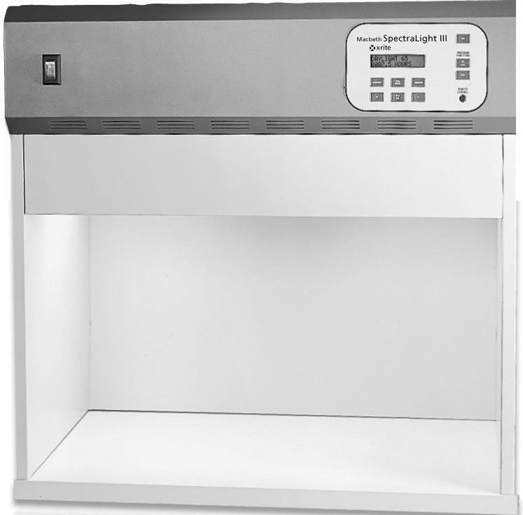
8 Figure 6. SpectraLight III Viewing Booth 10. The Spectralight Booth is now fully assembled. See Figure Place the viewing booth on the table or bench capable of holding a minimum of 300 lbs (136 kg). Note: The table or bench height should be determined by the average height of the observer and whether observations will be made from a standing or sitting position. 12. Carefully unpack and remove the overhead luminaire from its shipping container. 13. With its controls and indicators facing to the front, carefully place the luminaire atop the viewing booth. Align the luminaire with the positioning tabs on the viewing booth. Luminaire Positioning Tab Positioning Tab Assembled Booth Figure 7. Luminaire Placement Page 8
9 The SpectraLight III diffuser is shipped in a separate container and must be installed next. 14. Carefully unpack and remove the diffuser from its shipping container. Be careful not to scratch the interior of the booth. Make sure the hinge pins are carefully placed behind the Horizon lamps to avoid lamp breakage. 15. Insert the diffuser hinge pins into the front of the slotted receptacles located at the bottom rear corners of the luminaire housing. The smooth side of the diffuser should face the interior of the luminaire, and the textured side should face out, to the interior of the booth. Refer to Figure 8. Main Power Switch Diffuser Latch Horizon Lamp Notched Receptacles for Diffuser Hinge Pins Figure 8. Luminaire Showing Diffuser 16. Rotate the diffuser to its closed position and secure it in place with the latch. Ensure that the diffuser latch is secured before releasing. Failure to do so may result in the diffuser sliding out of position. 17. Plug SpectraLight III into a power source matching the voltage specified on the power label on the rear of the unit. Turn on the Main Power Switch located on the front panel. Note: Immediately upon power up, the unit will go through a brief system test to ensure that the voltage and electrical line are satisfactory. Testing Line appears in the front panel display. The incandescent lamps will be powered during the test. Once the test is complete, the unit is ready for operation Page 9
10 Overhead Luminaire Installation The following describes single- and dual-overhead luminaire installation. Do not install the overhead luminaire under a fire sprinkler system. Dissipated heat from the luminaire may cause the sprinkler system to activate. 1. Carefully unpack and remove the SpectraLight III from its shipping container. 2. Remove the eyebolts (four for the single overhead, eight for the dual overhead) from the accessory package and screw them into the weld nuts located on top of the unit. Refer to Figure 9. Eyebolts Figure 9. Overhead Luminaire In the following step, ensure adequate support. Each unit weighs 92 lbs. (41.7 kg). 3. Attach chains (not supplied) to each of the eyebolts and suspend the unit(s) at the appropriate height and angle over the work area. The luminaire should be installed so that it is a minimum of two feet from any wall. Refer to Figure " 8 1/2" 36" 30 ± 3 30 ± 3 31" ± 2" 6'0" ± 2" Table Table Figure 10. Recommended Overhead Luminaire Installation Page 10
11 SpectraLight III is shipped with its lamps and daylight filters installed. The diffuser is shipped in a separate container and must be installed at this point. 4. Carefully unpack and remove the diffuser from its shipping container. In the following step, make sure the hinge pins are carefully placed behind the Horizon lamps to avoid lamp breakage. 5. Insert the diffuser hinge pins into the front of the slotted receptacles located at the bottom rear corners of the luminaire housing. Refer to Figure 11. Diffuser Latch Horizon Lamps Notched Receptacles for Diffuser Hinge Pins Figure 11. Luminaire Showing Diffuser Mounting 6. Rotate the front of the diffuser to its closed position and secure it in place with the latch. 7. Connect the remote control (optional with the single unit) to the front panel at the location marked Remote. 8. For single-overhead installations, go to step 10. For dual overhead installations, repeat steps 4 through 6 for the second luminaire. 9. Connect the dual luminaire cable between the two luminaires. See Figure 12. Cable Rear of Unit Rear of Unit Figure 12. Dual Overhead Luminaire Cable Conection 10. Plug each luminaire into its own, separate 20 A circuit (one for each luminaire). Turn on the main power switch located on the front panel. Note: Immediately upon power up, the unit will go through a brief system test to ensure that the voltage and electrical line are satisfactory. Testing Line appears in the front panel display. The incandescent lamps will be powered during the test. Once the test is complete, the unit is ready for operation. Page 11
12 MAINTENANCE Cleaning the Diffuser, Daylight Filters, Lamps, and Reflectors To clean the unit; refer to Figure 13 and Figure 14, and proceed as follows: Main Power Switch Diffuser Latch Diffuser 1. Turn off the Main Power Switch before proceeding. Figure 13. Open Luminaire In the following step, make sure there are no objects in the way of the diffuser upon release and be careful to gently lower the diffuser. 2. Release the diffuser latch located at the front of the diffuser. 3. Lower the front of the diffuser to its completely opened position (vertical). In the following step, make sure the hinge pins are removed carefully to avoid Horizon lamp breakage. 4. Lift the diffuser up to remove the hinge pins from the slotted receptacles. 5. Wash the glass with water containing a mild detergent; rinse thoroughly, and air dry. The daylight filters and incandescent lamps get very hot during normal operation. Do not touch the filters or lamps; allow time for them to cool before cleaning. 6. Unscrew the quarter-turn fastener. See Figure 14 on the next page. Gently rotate the filter pack downward. Page 12
13 Hinge BLB Cool White Fluorescent Custom Fluorescent Horizon Filter Pack Hinge UV Illuminant "A" Horizon Quarter Turn Fastener Vent Custom Fluorescent Cool White Fluorescent Quarter Turn Fastener BLB Figure 14. Filter and Lamp Location 7. Slide the filter pack sideways and remove it. 8. Remove dust with a clean, dry, lint-free cloth. 9. Remove dirt and other foreign material with a spray-type window cleaner. AVOID EXCESSIVE MOISTURE. 10. Air dry and return the pack to the same position from which it was removed in step 6. Note: Ensure the filter pack is completely dry prior to operating the unit. Moisture may damage the filter when heat from the lamps is present. 11. Repeat steps 6 through 10 for the second filter pack. In the following step, make sure the hinge pins are removed carefully to avoid Horizon lamp breakage. 12. Remove dirt from the daylight lamp reflectors with a clean cloth dampened with warm water or an ammonia-based window cleaner. 13. Replace the daylight filter packs. 14. Remove dust from all remaining lamps with a clean, dry, lint-free cloth. 15. Remove dirt from all the remaining reflectors with a clean cloth dampened with warm water or an ammonia-based window cleaner. Air dry all components. 16. Install and secure the diffuser. Make sure the hinge pins are carefully placed behind the horizon lamps to avoid lamp breakage. 17. Restore power through the Main Power Switch and begin normal operation. Page 13
14 Replacing Lamps Replace burned out lamps immediately in order to maintain the overall performance standards of the fixture. We recommend replacing lamps in complete sets. For example, if one daylight lamp burns out, replace both of them. Refer to Parts List later in this document. Lamp Type Replace Every Lamp Type Replace Every Simulated Daylight 400 hours Cool White Fluorescent 4000 hours Horizon 2000 hours Ultraviolet 30 Watt 4000 hours Illuminant A 2000 hours Ultraviolet 6 Watt 4000 hours Allow time for the daylight filters or incandescent lamps to cool before handling them. Always use lens paper or equivalent when handling the lamps. Skin oils interfere with their performance. 1. Turn off the Main Power Switch before proceeding. 2. For booth installations, remove the front panel. 3. Release the front diffuser latch. Lower the front of the diffuser to its opened position (vertical). 4. Unscrew the quarter-turn fastener (see Figure 14.) and lower the diffuser. Slide the filter packs sideways to remove them. Note: Take special care to remove the filter packs. Improper handling during removal or replacement may result in breakage. 5. Push one end of the lamp into the spring loaded socket with pressure to release the other end from its socket. 6. Lift the lamp clear of both sockets and discard in an appropriate receptacle. 7. Using a piece of lens paper (or equivalent) placed between your thumb and forefinger; insert the replacement lamp into the sockets. Refer to Figure 15. Grasp in middle of lamp Socket Figure 15. Tungsten-Halogen Lamp Replacement 8. After the lamp has been replaced, replace the filter packs and secure them in place. 9. Reset the lamp time meter using the procedure Resetting the Lamp Time Meter on the following pages. Certification Program X-Rite is pleased to offer a Preventative Maintenance and Certification service for users of SpectraLight viewing systems. This factory authorized service provides a Certificate of Performance with traceability to A2LA (American Association for Laboratory Accreditation) for the line of SpectraLight viewing systems. Annual completion of this service is recommended and will provide you with the assurance that your system meets the specified requirements for color rendering quality. Page 14
15 OPERATION Note: When powering off the SpectraLight III using the Main Power Switch, wait at least 5 seconds before you power it on again. This will enable all of the firmware and hardware to properly shut off. If you attempt power on less than 5 seconds after the power off, the unit may not power up. If this occurs, power off the unit, wait at least 5 seconds, and then power it on using the Main Power Switch. Source Off Button Display shows light source and hour meter Program Set/ Save Button Lamp Source Buttons Program Run Button Remote Control Receptacle Selecting a Light Source To select a light source for viewing a sample, simply press and release the button on the front panel for the light source. The source remains on until you select another light source or press the Source Off button on the membrane panel. Using the Source Off Button The Source Off Button should be used to turn off a selected lamp. You can think of using this button as putting the unit in idle until another lamp source is selected. Do not use the Source Off Button to power off the entire unit. You should use the Main Power Switch (located to the left of the Membrane Panel) to completely cut power to the unit for maintenance purposes. Programming the SpectraLight III The SpectraLight III can be programmed to power a sequence of light sources, each for a specified period of time. The program is helpful if you want to view a sample under several light sources in succession and focus on the sample s appearance rather than operating the front panel. To set up the program, proceed as follows: 1. Press and hold the Set/Save button until PGM: appears in the front panel display. 2. Press and hold the light source button for the first source in the sequence. Hold the button for the number of seconds the source should be powered in the sequence and then release. 3. Seconds= ## appears in the front panel display. ## indicates the number of seconds the button has been held. For example, press and hold the Cool White button for three seconds. Seconds=03 appears in the display. 4. PGM: XX appears in the display. XX indicates the light source you selected. For example, PGM: CW indicates that Cool White Fluorescent is the first source in the sequence. 5. Repeat step 2 for the next light source in the sequence. Page 15
16 6. PGM: XX YY appears in the display. YY indicates the second light source in the sequence. For example, PGM:CW HR indicates that Cool White Fluorescent is the first source and Horizon is the second source in the sequence. 7. Repeat step 2 for the remaining light sources in the sequence. 8. Press the Set/Save Button to save the program. Program Saved appears in the display. You are now finished with programming the SpectraLight III. 9. To change the program at any time, repeat the above sequence of steps and any previous program is erased. Running the Program To run the program on a single unit, proceed as follows: 1. Press the Run button. The unit indicates L/AUTO in the display. 2. The SpectraLight III runs the program. The sources are powered in the sequence you programmed. The program continually runs until you press the Source Off button. To run the program in a Master/Slave Setup (daisy chain configuration), proceed as follows: 1. Press the Run button twice on the master unit. The unit indicates R/AUTO in the display. 2. The SpectraLight III runs the program. The sources are powered in the sequence you programmed on the master and slave units. The program continually runs until you press the Source Off button on the master unit. Note: You should not press the UV source button while the program is running. If this occurs, the program will stop regardless if it is finished. You must press another source button to reset the unit and then run the program again. If you need UV in the program, you must re-program the unit. Follow the instructions described in "Programming the SpectraLight III". Using the Automatic Shut-Off Feature The SpectraLight III Daylight lamps have the shortest life among all the lamps in the unit. To reduce the frequency of Daylight lamp replacement, the SpectraLight III has a feature called Automatic Shut-Off. This feature automatically switches the lamp source from Daylight to Cool White Fluorescent after a period of five minutes. This feature is helpful if a user leaves the booth with the Daylight source selected and does not switch to another source. The Automatic Shut-Off feature is automatically enabled and is indicated by an * in the display. You can temporarily disable the Automatic Shut-Off feature. To do so, proceed as follows: 1. While the Daylight source is selected, press the Daylight button. 2. AUTO SHUTOFF DE-ACTIVATED appears in the display. Notice that the * no longer appears in the display. 3. If the Daylight lamp is powered for more than five minutes, it remains selected until you select another source. The Automatic Shut-Off Feature is enabled again by turning the Daylight source off and then on again. To do this, proceed as follows: 1. While the Daylight source is selected, press the Source Off button. The Daylight source is turned off. 2. Press the Daylight source button. DAYLIGHT * appears in the display. The Auto Shut-Off is enabled. Resetting the Lamp Time Meter The SpectraLight III allows the user to replace lamps. After lamp replacement, you should reset the time meter for the new lamp. To reset the lamp time meter, proceed as follows: 1. Press and hold the source button for the replaced lamp for five seconds. 2. PRESS SET/SAVE TO CONFIRM RESET appears in the display. 3. Press the Set/Save button. 4. The hours are set to zero (0). Page 16
17 Interpreting Diagnostic Messages The SpectraLight III may display one of these diagnostic messages in the event that a situation has occurred which prevents the SpectraLight III from operating normally. The messages and troubleshooting suggestions are listed below. I got this message... What does it mean? What should I do? Over temperature The unit is overheating. 1) Turn off the unit using the Main Power Switch. 2) Make sure there is nothing on top of the unit blocking airflow. If so, remove the object and turn on the unit. 3) If no objects are found or the message remains after you turn on the unit, proceed to step 4. 4) Call X-Rite for assistance. Line Problem Daylight Lamp Burned Out There is an electrical power problem. The Daylight Lamp needs to be replaced. 1) Turn off the unit and then turn on the unit. 2) If the message remains, call X-Rite for assistance. 1) Turn off the unit using the Main Power Switch. 2) Follow the procedure Replacing Lamps on the previous pages. Page 17
18 Parts: Consult your X-Rite Price List for additional Lamp Kit Options or call your local X-Rite office. SPL (Daylight) Lamp Kit A-L/SPLD This kit consists of two (2) 750 Watt Tungsten Halogen lamps. Two (2 )required for the SPL III. Sold in packages of two (2) or as part of a specific lamp kit. SPL (Horizon) Lamp Kit A-L/SPLH This kit consists of four (4) 500 Watt Tungsten Halogen lamps. Four (4) required for the SPL III. Sold in packages of four (4) or as part of a specific lamp kit. SPL (Illuminant A ) Lamp Kit A-L/SPLIA This kit consists of two (2) 150 Watt Incandescent lamps. Two (2)required for the SPL III. Sold in packages of two (2) or as part of a specific lamp kit. SPL (CWF) 36" Lamp Kit A-L/SPLCW This kit consists of two (2) F30T8/CW Cool White Fluorescent lamps. Two (2) required for the SPL III. Sold in packages of two (2) or as part of a specific lamp kit. SPL (TL84) 36" Lamp Kit A-L/SPL84 This kit consists of two (2), F30T8/TL84 Fluorescent lamps. Two (2) lamps required for the SPL III. Sold in packages of two (2) or as part of a specific lamp kit. SPL (U30) 36" Lamp Kit A-L/SPLU30 This kit consists of two (2), F30T12/U30 Ultralume 30 Fluorescent lamps. Two (2) required for the SPL III. Sold in packages of two (2) or as part of a specific lamp kit. SPL (Ultraviolet 30 Watt) 36" Lamp Kit A-L/SPLUV This kit consists of two (2) F30T8/BLB Ultraviolet lamps. Two (2) required for the SPL III. Sold in packages of two (2) or as part of a specific lamp kit. SPL (Ultraviolet 6 Watt) Lamp Kit A-L/SPLUV6W This kit consists of two (2) F6T5/BLB Ultraviolet lamps. One (1) required for the SPL III. Sold in packages of two (2) or as part of a specific lamp kit. SPL (U35) 36" Lamp Kit A-L/SPLU35 This kit consists of two (2), F25T8/U35 Ultralume 35 Fluorescent lamps, one (1) SPLIII-510 Instruction sheet, one (1) SD43-SPL-U30 Label, and one (1) SD43-SPL-CWF Label. SPL III (TL84) Complete Lamp Kit A-LK/SPL84 This kit consists of two (2) 750 Watt Tungsten Halogen Daylight lamps, four (4) 500 Watt Tungsten Halogen Horizon lamps, two (2) 150 Watt Incandescent lamps, two (2) F30T8/TL84 Fluorescent lamps, two (2) F30T8/BLB UV lamps, and one (1) F6T5/BLB UV lamp. The quantities provided in kit represent the number of each lamp required for each SpectraLight III. Lamps are sold in packages of fifteen (15) or as part of a specific lamp kit. SPL III (U30) Complete Lamp Kit A-LK/SPLU30 This kit consists of two (2) 750 Watt Tungsten Halogen Daylight lamps, four (4) 500 Watt Tungsten Halogen Horizon lamps, two (2) 150 Watt Incandescent lamps, two (2) F30T8/U30 Fluorescent lamps, two (2) F30T8/BLB UV lamps, and one (1) F6T5/BLB UV lamp. The quantities provided in kit represent the number of each lamp required for each SpectraLight III. Lamps are sold in packages of fifteen (15) or as part of a specific lamp kit. SPL III Daylight Filter Pack (D75) VB or OVHD A-FP/SPL75 Patented D75 North Sky Daylight at 7500 K filter pack assembly. For SPL III Viewing Booths only. Two (2) required for the SPLIII. Sold in packages of two (2). SPL III Daylight Filter Pack (D65) VB or OVHD A-FP/SPL65 Patented D65 Average North Sky Daylight at 6500 K filter pack assembly. For SPL III Viewing Booths only. Two (2) required for the SPL III. Sold in packages of two (2). SPL III Daylight Filter Pack (D50) VB or OVHD A-FP/SPL50 Patented D50 Noon Sky Daylight at 5000 K filter pack assembly. For SPL III Viewing Booth or Overhead Luminaire. Two (2) required for the SPL III. Sold in packages of two (2). SPL Diffuser and Door Assembly A-AK/SPLDD Prismatic water white glass diffuser. For SPL III Viewing Booth or Overhead Luminaire. One (1) required for the SPL III. Sold in packages of one (1). SPL Remote Control Kit A-CK/SPLR Tethered remote control for use with the SPL III Viewing Booth or Overhead Luminaire. X-Rite makes no warranty of any kind with regard to the material contained in this manual, including implied warranties or fitness for a particular purpose. X-Rite shall not be liable for errors contained herein or for incidental or consequential damages in connection with the performance or use of this material. This manual is the copyright of X-Rite. Any reproduction of the publication in whole or in part without the express permission of X-Rite is a breach of this copyright. SpectraLight is a registered trademark of X-Rite, Incorporated. Page 18
19
20 Corporate Headquarters X-Rite, Incorporated th Street SE Grand Rapids, Michigan Phone or Fax or European Headquarters X-Rite Europe GmbH Althardstrasse Regensdorf Switzerland Phone (+41) Fax (+41) Asia Pacific Headquarters X-Rite Asia Pacific Limited 36th Floor, No. 169 Electric Road Hong Kong, China Phone (852) Fax (852) Please visit for a local office near you. P/N Rev. E
MetaVue. User Manual. VS3100 Spectrophotometer. P/N VS3-500 Rev. A
 MetaVue VS3100 Spectrophotometer User Manual P/N VS3-500 Rev. A CE Declaration Hereby, X-Rite, Incorporated, declares that this model is in compliance with the essential requirements and other relevant
User Instructions. 16 SCB Sync Station.
 User Instructions 16 SCB Sync Station Contents Overview... 1 Specifications... 1 Compliance and approvals... 2 Safety instructions... 3 Set up... 4 How to charge multiple devices... 4 How to synchronize
Instant 802.3af Gigabit Outdoor PoE Converter. Model: INS-3AF-O-G. Quick Start Guide
 Instant 802.3af Gigabit Outdoor PoE Converter Model: INS-3AF-O-G Quick Start Guide QUICK START GUIDE Introduction Thank you for purchasing the Ubiquiti Networks Instant 802.3af Gigabit Outdoor PoE Converter.
AITech ProA/V Media Extender 5GHz Digital
 AITech ProA/V Media Extender 5GHz Digital 5 GHz Wireless Digital Media Transmitter and Receiver User Manual Table of Contents 1. Package Contents 2. Panels and Functions AV Sender AV Receiver 3. Setup
Quick Start. About the Camera. Power Button Battery Status Record Button Rotating Lens Record Status Memory Status Resolution Switch
 Product Guide 1 Quick Start About the Camera a b c d e f g h i j k l Power Button Battery Status Record Button Rotating Lens Record Status Memory Status Resolution Switch USB Charge Indicator Battery Latch
Operation Manual VMS 3.0 Video System
 Operation Manual VMS 3.0 Video System for the AlterG Anti-Gravity Treadmill 1 This manual covers operation procedures for the following AlterG products: AlterG Video System model VMS 3.0 NOTE: The following
Quick Start Guide ABOUT THE CAMERA
 User Manual Quick Start Guide ABOUT THE CAMERA A Record Status B Record Switch C Rotating Lens D Battery Slot E Battery Latch F Card Format Button G USB H Format Switch I MicroSD card J Memory Status K
Access Converter/ 3. Operation Manual. International Headquarters. European Headquarters. B&B Electronics. 707 Dayton Road Ottawa, IL USA
 Access Converter/ 3 International Headquarters B&B Electronics Operation Manual 707 Dayton Road Ottawa, IL 61350 USA Phone (815) 433-5100 General Fax (815) 433-5105 Email: support@bb-elec.com Website:
Tube Roller Shakers. User Guide. Version 1.2
 Tube Roller Shakers User Guide Version 1.2 Control panel Rollers Side retaining panels Analog models LED display Drip tray (not visible) Digital models Power On/Off and control dial Roller retaining panel
1X4 HDMI Splitter with 3D Support
 AV Connectivity, Distribution And Beyond... VIDEO WALLS VIDEO PROCESSORS VIDEO MATRIX SWITCHES EXTENDERS SPLITTERS WIRELESS CABLES & ACCESSORIES 1X4 HDMI Splitter with 3D Support Model #: SPLIT-HDM3D-4
EN - English Washington Street Melrose, MA Phone Toll Free Revision 4 20/06/17
 - English... 1 Instruction Manual Vortex Mixer, Mini Fix Speed, VXMNFS Vortex Mixer, Mini Analog, VXMNAL Vortex Mixer, Mini Digital, VXMNDG Vortex Mixer, Mini Pulsing, VXMNPS 99 Washington Street Melrose,
Congratulations on your mcable purchase! The mcable delivers the best possible picture to your HD or 4K TV by up-converting 480p and 720p content to
 1 USER GUIDE Congratulations on your mcable purchase! The mcable delivers the best possible picture to your HD or 4K TV by up-converting 480p and 720p content to 1080p, up-converting 1080p content to near-native
Website: Tel: ADDRESS: 6475 Las Positas Rd. Livermore, CA Item No. E5B/E5S Installation Guide
 Website: www.flexispot.com Tel: -855-4-808 ADDRESS: 6475 Las Positas Rd. Livermore, CA 9455 Item No. E5B/E5S Installation Guide Specifications Step Column 3 Max. Weight Capacity 0 Ibs (00 kg) Speed 38mm/s
5 Port DVI Splitter VIDEO WALLS VIDEO PROCESSORS VIDEO MATRIX SWITCHES EXTENDERS SPLITTERS WIRELESS CABLES & ACCESSORIES
 AV Connectivity, Distribution And Beyond... VIDEO WALLS VIDEO PROCESSORS VIDEO MATRIX SWITCHES EXTENDERS SPLITTERS WIRELESS CABLES & ACCESSORIES 5 Port DVI Splitter Model #: SPLIT-DVI-5 2013 Avenview Inc.
Instruction Manual Fixed Speed Vortex Mixer Analog Vortex Mixer Digital Vortex Mixer Pulsing Vortex Mixer
 Instruction Manual Fixed Speed Vortex Mixer Analog Vortex Mixer Digital Vortex Mixer Pulsing Vortex Mixer Table of Contents Package Contents............ 1 Warranty............ 1 Installation............
RemotePoint. Navigator. User s Manual VP4150
 RemotePoint Navigator User s Manual VP4150 LASER Safety Statement CAUTION: Use of controls or adjustments or performance of procedures other than those specified herein may result in hazardous radiation
Tube Rotator. User Guide. Version 1.2
 Tube Rotator User Guide Version 1.2 Figure 1: Fixed Speed Model Tube holder spindle Tilt adjustment wheel IEC power inlet socket (at rear) Power on/off switch Figure 2: Variable Speed Model Tube holder
Introduction. Package Contents. Installation Requirements
 Security Camera Security Camera Introduction Introduction Thank you for purchasing the aircam Dome. This Quick Start Guide is designed to guide you through the installation of the aircam Dome and show
APSPB PUSH BUTTON ZERO Installation Manual
 APSPB PUSH BUTTON ZERO Installation Manual CARDINAL SCALE MFG. CO. 8527-0579-0M Rev A 203 E. Daugherty, Webb City, MO 64870 USA Printed in USA 12/14 Ph: 417-673-4631 Fax: 417-673-2153 www.detectoscale.com
ACCESSORIES MANUAL PART NUMBER: TNP500. Universal Tilt N Plug Interconnect Box USER'S GUIDE
 MANUAL PART NUMBER: 400-0091-003 TNP500 Universal Tilt N Plug Interconnect Box USER'S GUIDE INTRODUCTION Your purchase of the TNP100 Tilt N Plug Interconnect Box is greatly appreciated. We are sure you
SC-C1M SiriusConnect TM Vehicle Tuner
 SC-C1M SiriusConnect TM Vehicle Tuner For Special Market Applications Installation Guide Congratulations on the Purchase of your new SIRIUS SC-C1 SiriusConnect TM Vehicle Tuner. The SC-C1M is packaged
HIIT Console OWNER S MANUAL
 HIIT Console OWNER S MANUAL IMPORTANT SAFETY INSTRUCTIONS CONSOLE SAFETY INSTRUCTIONS All connected products/equipment are for fitness and health purposes only. Any readings/values should not be used for
CHECK LINE. Model LS-36-LED. Stationary Stroboscope. Operating Manual BY ELECTROMATIC
 CHECK LINE BY ELECTROMATIC Stationary Stroboscope Model LS-36-LED Operating Manual Table of Contents 1.0 Introduction... 02 1.1 Unpacking 1.2 Optional Accessories 2.0 Safety Information... 3 3.0 Controls...
ACCESSORIES MANUAL PART NUMBER: PRODUCT REVISION: 1 TNP100. Tilt N Plug Interconnect Box USER'S GUIDE
 MANUAL PART NUMBER: 400-0091-001 PRODUCT REVISION: 1 TNP100 Tilt N Plug Interconnect Box USER'S GUIDE INTRODUCTION Your purchase of the TNP100 Tilt N Plug Interconnect Box is greatly appreciated. We are
User Manual MagniLink Mira
 User Manual MagniLink Mira LVI Low Vision International Verkstadsgatan 5 Tel: +46 470 727700 E-mail: info@lvi.se 352 46 Växjö SWEDEN Fax: +46 470 727725 Internet: www.lvi.se CONTENTS 1. GENERAL INFORMATION...
Contents. Instruction Manual T-Rex Page 2 of 16 Release 1.01
 Contents 1 Safety Precautions... 3 2 Introduction:... 5 3 Theory of Operation... 7 4 Unpacking Procedure... 8 5 Operating TR-Mark III with T-Rex... 9 6 Operating a TR-Mark II with a T-Rex... 13 7 Technical
SAFETY WARNINGS AND GUIDELINES INTRODUCTION CUSTOMER SERVICE
 SAFETY WARNINGS AND GUIDELINES Prior to operation, check the unit and power cord for physical damage. Do not use if physical damage has occurred. Before plugging the unit into a power outlet, ensure that
Information. Marketing Description. For Models: DA2133i. 2113i. User s Guide Rev B
 Casework Model Number User s Marketing Description Information For Models: xxxx FCC (-001) (All) xxxx FTC (All) (-002) DA2133i 2113i User s Guide 003-1891-00 Rev B Table of Contents Important Information
EASY SET UP GUIDE. Thank you! You now own Flapit. Tell us about Flapit and you #flapitcounter
 Thank you! You now own Tell us about and you #flapitcounter EASY SET UP GUIDE EASY SET UP 1 Power up 3 Find configuration page Plug in the device http://192.168.1.1 2 Find flapit network Launch your internet
SAFETY WARNINGS AND GUIDELINES INTRODUCTION CUSTOMER SERVICE
 SAFETY WARNINGS AND GUIDELINES Prior to operation, check the unit and power cord for physical damage. Do not use if physical damage has occurred. Before plugging the unit into a power outlet, ensure that
GE Interlogix Fiber Options S700V & S702V. Instruction Manual FIBER-OPTIC VIDEO TRANSMISSION SYSTEM
 g GE Interlogix Fiber Options Instruction Manual S700V & S702V FIBER-OPTIC VIDEO TRANSMISSION SYSTEM Federal Communications Commission and Industry Canada Radio Frequency Interference Statements This equipment
3G/HD/SD-SDI to HDMI Converter
 3G/HD/SD-SDI to HDMI Converter Model #: 3G/HD/SD-SDI to HDMI Converter 2010 Avenview Inc. All rights reserved. The contents of this document are provided in connection with Avenview Inc. ( Avenview ) products.
IFS Fiber Module Installation & Operation Instructions
 VT740-DRDT VT740-DRDT-R3 VT7430-DRDT VT7430-DRDT-R3 IFS Fiber Module Installation & Operation Instructions VR740-DRDT VR740-DRDT-R3 VR7430-DRDT VR7430-DRDT-R3 P/N 06784 REV B ISS 0JUL VIDEO INPUT 3 4 POWER
USERS GUIDE MCX-HTS. HDMI to 3G SDI Converter. Manual Number:
 USERS GUIDE MCX-HTS HDMI to 3G SDI Converter i Manual Number: 151226 SAFETY INSTRUCTIONS Please review the following safety precautions. If this is the first time using this model, then read this manual
Basic Vortex Mixer Standard Vortex Mixer Advanced Vortex Mixer Pulsing Vortex Mixer
 Instruction Manual Manual Basic Vortex Mixer Standard Vortex Mixer Advanced Vortex Mixer Pulsing Vortex Mixer Table of Contents Package Contents............... 1 Warranty............... 1 Installation...............
Universal Wireless HDTV Adapter
 Universal Wireless HDTV Adapter F7D4555v1 User Manual Table of Contents CHAPTER 1 INTRODUCTION... 1 Package Contents... 1 Features... 1 LEDs... 2 CHAPTER 2 INITIAL INSTALLATION... 4 Requirements... 4 Procedure...
ALPHA Personal Priority Display User Manual
 ALPHA Personal Priority Display User Manual PERSONAL PRIORITY DISPLAY 1997 Adaptive Micro Systems Form No. 9708-5002 12/10/97 i NOTE: Due to continuing product innovation, specifications in this document
Children cannot always recognize potential hazards properly. This 5.1 system is not designed for operation in a heavy industry environment.
 5.1 FLAT PANEL SPEAKER SYSTEM WITH POWERED SUBWOOFER Table of Contents: SAFETY AND SERVICE... 2 Operational Safety... 2 Location... 2 Ambient Temperature... 3 Electromagnetic Compliance... 3 Service...
Garmin GC 10 Marine Camera Instructions
 Garmin GC 10 Marine Camera Instructions FCC Compliance This device complies with part 15 of the FCC Rules. Operation is subject to the following two conditions: (1) this device may not cause harmful interference,
Folding Beauty Dish INSTRUCTIONS
 Folding Beauty Dish INSTRUCTIONS Precautions Please read and follow these instructions, and keep this manual in a safe place. Keep this unit away from water and any flammable gases or liquids. Use only
PRO Mixer Distro User Guide
 PRO Mixer Distro 17. The apparatus shall be connected to a mains socket outlet with a protective earthing connection. 18. Mains plug is used as the disconnect device. It shall remain readily operable and
Mini Projector User s Guide
 Mini Projector User s Guide Please read this manual before Model P50 Table of Contents 1. Table of Contents---------------------------------1 2. Warnings-----------------------------------------2 3. Accessories---------------------------------------4
MonoBright LED DAYLIGHT 750
 MonoBright LED DAYLIGHT 750 USER MANUAL MonoBright LED Daylight 750 - USER MANUAL 1 MonoBright LED DAYLIGHT 750 INTRODUCTION Thank you for choosing Genaray. The Genaray MonoBright LED Daylight 750 incorporates
TO THE INSTALLER: BE SURE TO LEAVE THIS MANUAL WITH THE OWNER.
 Fixed Frame Screen Owner s Manual To the Owner Installation Instructions Screen Care CFS-010517 Maintenance TO THE INSTALLER: BE SURE TO LEAVE THIS MANUAL WITH THE OWNER. Printed in U.S.A. Stewart Filmscreen
Operating Instructions
 Operating Instructions SDI Input board Model No. AV-HS04M1 РУССКИЙ FRANÇAIS DEUTSCH ENGLISH ESPAÑOL ITALIANO Before operating this product, please read the instructions carefully and save this manual for
SCRIPT INNOVATIONS C- RAY PILL COUNTER OPERATORS MANUAL
 SCRIPT INNOVATIONS C- RAY PILL COUNTER OPERATORS MANUAL VERSION 2.0 Providers of Enhanced Pharmaceutical Equipment FCC Statement This device complies with part 15 of the FCC Rules. Operation is subject
User Guide. Single-Link DVI Active Cable Extender. DVI-7171c
 User Guide Single-Link DVI Active Cable Extender DVI-7171c TABLE OF CONTENTS SECTION PAGE PRODUCT SAFETY...1 PRODUCT LIABILITY...1 1.0 INTRODUCTION...2 2.0 SPECIFICATIONS...3 3.0 PACKAGE CONTENTS...4 4.0
8 Port HD/SD-SDI Video Switch with 2 Port Splitter
 8 Port HD/SD-SDI Video Switch with 2 Port Splitter User s Guide Models SW-HDSDI-8X2 2008 Avenview Inc. All rights reserved. The contents of this document are provided in connection with Avenview Inc. (
Chapter 1 : FCC Radiation Norm...3. Chapter 2 : Package Contents...4. Chapter 3 : System Requirements...5. Chapter 4 : Hardware Description...
 Table of Contents Chapter 1 : FCC Radiation Norm...3 Chapter 2 : Package Contents...4 Chapter 3 : System Requirements...5 Chapter 4 : Hardware Description...6 Chapter 5 : Charging Your Video Watch...7
Linear Array with Intensity Adjustment
 Datasheet High-Power Lighting with Intensity Adjustment for use with Vision Systems For complete technical information about this product, including dimensions, accessories, and specifications, see www.bannerengineering.com/lineararraylights.
Transvue HDMI 4K2K Scaler
 Transvue HDMI 4K2K Scaler UPSCALE AND DOWNSCALE HDMI Installation and Operation Manual 10707 Stancliff Road Houston, Texas 77099 Phone: (281) 933-7673 techsupport@rose.com LIMITED WARRANTY Rose Electronics
Kramer Electronics, Ltd. USER MANUAL. Model: VM Video Component Distributor
 Kramer Electronics, Ltd. USER MANUAL Model: VM-1045 Video Component Distributor Contents Contents 1 Introduction 1 2 Getting Started 1 2.1 Quick Start 1 3 Overview 3 4 Your VM-1045 Video Component Distributor
X-Series Expansion Cards. X-Video Card
 X-Series Expansion Cards X-Video Card User s Guide v1.0 - February 2006 Warnings FCC warning This equipment has been tested and found to comply with the limits for a Class A digital device, pursuant to
Fiber Converters TFC-110 Series. ŸQuick Installation Guide (1)
") Fiber Converters TFC-11 Series ŸQuick Installation Guide (1) 1. Before You Start Package Contents ŸFiber Converter ŸMulti-Language Quick Installation Guide ŸPower Adapter If any of the above contents are
Fiber Converters TFC-11 Series ŸQuick Installation Guide (1) 1. Before You Start Package Contents ŸFiber Converter ŸMulti-Language Quick Installation Guide ŸPower Adapter If any of the above contents are
Quintet SL. Owner s Manual
 Quintet SL Owner s Manual QUINTET SL SPEAKER SYSTEM IMPORTANT SAFETY INSTRUCTIONS 1. READ these instructions. 2. KEEP these instructions. 3. HEED all warnings. 4. FOLLOW all instructions. 5. DO NOT use
CrystalView DVI Micro-DL Extender
 CrystalView DVI Micro-DL Extender Quick Start Guide CrystalView DVI Micro Dual-Link Fiber Extender Rose Electronics 10707 Stancliff Road Houston, Texas 77099 Phone (281) 9337673 Limited Warranty Rose Electronics
VideoSplitter HDMI 4K PT
 VideoSplitter HDMI 4K PT 4K HDMI Splitter Pigtail Type Installation and Operation Manual 10707 Stancliff Road Houston, Texas 77099 Phone: (281) 933-7673 tech-support@rose.com LIMITED WARRANTY Rose Electronics
ACCESSORIES MANUAL PART NUMBER: PRODUCT REVISION: 1 PNP202. Interconnect Box USER'S GUIDE
 MANUAL PART NUMBER: 400-0109-001 PRODUCT REVISION: 1 PNP202 Interconnect Box USER'S GUIDE INTRODUCTION Your purchase of the PNP202 Interconnect Box is greatly appreciated. We are sure you will find it
Model 570 Fiber Optic
 Model 570 Fiber Optic Transmit Trigger Package The World Leader in Subsurface Imaging December, 2005 Geophysical Survey Systems, Inc. Tel 603.893.1109 Fax 603.889.3984 sales@geophysical.com www.geophysical.com
APS W 12 inch. APS W 15 inch. 2 Way Active PA System with 3 Channel Mixer. 2 Way Active PA System with 3 Channel Mixer.
 P/N 604212 APS 12 400W 12 inch 2 Way Active PA System with 3 Channel Mixer P/N 604215 APS 15 400W 15 inch 2 Way Active PA System with 3 Channel Mixer User's Manual SAFETY WARNINGS AND GUIDELINES Do not
DisplayPort Signal Booster - 4K
 DisplayPort Signal Booster - 4K DPBOOST *actual product may vary from photos FR: Guide de l utilisateur - fr.startech.com DE: Bedienungsanleitung - de.startech.com ES: Guía del usuario - es.startech.com
One (1) fiber Detachable HDMI Extender
 fiber Detachable HDMI Extender") ㅕ Manual Contents Manual Contents 1-0 Welcome! Product Description 1-1 System Requirements for Setup 1-2 Installation 1-3 Troubleshooting 1-5 Maintenance, Technical Support 1-6 Product Specifications 1-7
ㅕ Manual Contents Manual Contents 1-0 Welcome! Product Description 1-1 System Requirements for Setup 1-2 Installation 1-3 Troubleshooting 1-5 Maintenance, Technical Support 1-6 Product Specifications 1-7
led port-a-cube CT-LLED CT-SLED INSTRUCTIONS
 led port-a-cube CT-LLED CT-SLED INSTRUCTIONS Introduction Congratulations on purchasing the Angler LED Port-a-Cube. The Angler LED Port-a-Cube is a foldable and portable lighting solution for product photography.
HDMI Signal Booster - 4K
 HDMI Signal Booster - 4K HDBOOST4K *actual product may vary from photos FR: Guide de l utilisateur - fr.startech.com DE: Bedienungsanleitung - de.startech.com ES: Guía del usuario - es.startech.com NL:
Indoor/Outdoor Analog Wired Camera Model P-520 USER'S MANUAL
 Indoor/Outdoor Analog Wired Camera Model P-520 USER'S MANUAL WELCOME Welcome Thank you for choosing First Alert for your security needs! For more than half a century, First Alert has made the home-safety
User Guide. HDMI Active Cable Extender. DVI-7370c
 User Guide HDMI Active Cable Extender DVI-7370c TABLE OF CONTENTS SECTION PAGE PRODUCT SAFETY...1 PRODUCT LIABILITY STATEMENT........................ 1 1.0 INTRODUCTION...2 2.0 SPECIFICATIONS...3 3.0 PACKAGE
TR6102HD HDTV/DVD/COMPONENT VIDEO TO RGBHV TRANSCODER USER S GUIDE
 MANUAL PART NUMBER: 400-0031-003 PRODUCT REVISION: 1 HDTV/DVD/COMPONENT VIDEO TO RGBHV TRANSCODER USER S GUIDE INTRODUCTION Thank you for your purchase of the Transcoder. We are certain that you will find
UDRC13 ACCESSORY CAMERA Owner s Manual
 UDRC13 ACCESSORY CAMERA Owner s Manual Compatible with UDR444 Wireless Video Surveillance System If any items are missing or damaged, contact our Customer Care Line immediately. Never use damaged products!
MonoBright LED DAYLIGHT 1200
 MonoBright LED DAYLIGHT 1200 USER MANUAL MonoBright LED Daylight 1200 - USER MANUAL 1 MonoBright LED DAYLIGHT 1200 INTRODUCTION Thank you for choosing Genaray. The Genaray MonoBright LED 1200 incorporates
DVI Rover 700 User Guide
 DVI Rover 700 User Guide Featuring ExtremeDVI Technology DVI Rover 700 This document applies to Part Numbers: 00-00106 through 00-00141 inclusive. FCC Radio Frequency Interference Statement Warning The
User Manual. Tensioned Screens. Website: Tel:
 User Manual Tensioned Screens Website: www.luxburgvisual.com Email: support@luxburgvisual.com Tel: 0044 207 237 4842 Table of Contents SAFETY INFORMATION... 3 IMPORTANT SAFETY INSTRUCTION... 3 SETTING
ViewSonic. N4280p LCD TV. - User Guide. - Guide de l utilisateur. - Guía del usuario. Model No. : VS M
 LCD TV - User Guide - Guide de l utilisateur - Guía del usuario Model No. : VS11838-1M Compliance Information FCC Statement This device complies with part 15 of FCC Rules. Operation is subject to the following
TruVision High Definition TVI Bullet Camera Installation Guide
 TruVision High Definition TVI Bullet Camera Installation Guide TVB-2402/TVB-4402 TVB-2404/TVB-4404 P/N 1072938-EN REV A ISS 10MAR15 Contents Product overview 2 Camera description 4 Installation 6 Programming
8 Port HD/SD-SDI Switch
 8 Port HD/SD-SDI Switch User s Guide Models SW-HDSDI-8X1 2008 Avenview Inc. All rights reserved. The contents of this document are provided in connection with Avenview Inc. ( Avenview ) products. Avenview
Subwoofers ENGLISH FRANCAIS SPANISH DEUTSCH OWNER S MANUEL MODE D EMPLOI MANUEL DEL USUARIO BEDIENUNGSANLEITUNG
 ENGLISH FRANCAIS SPANISH DEUTSCH Subwoofers OWNER S MANUEL MODE D EMPLOI MANUEL DEL USUARIO BEDIENUNGSANLEITUNG Titan 5.6 Titan 7.6 MK2 Titan 11.6 MK2 Titan 15.6 MK2 MOSSCADE BP 306-94709 Maisons-Alfort
User Manual TL-2X1-HDVC 2x1 HDMI & VGA Switcher with Control All Rights Reserved Version: TL-2X1-HDVC_160630
 User Manual TL-2X1-HDVC 2x1 HDMI & VGA Switcher with Control All Rights Reserved Version: TL-2X1-HDVC_160630 Preface Read this user manual carefully before using this product. Pictures shown in this manual
AWT150C/AWT150CS/ AWT151C CCD Camera
 AWT150C/AWT150CS/ AWT151C CCD Camera ISSUED OCTOBER 2018 WARNING Failure to follow all instructions and safety precautions in this manual, in the vehicle and body manufacturers' manuals and on the safety
User Instructions. Warning! To prevent or reduce the risk of electrical shock or fire, do
 7/07 User Instructions American DJ 4295 Charter Street Los Angeles Ca. 90058 www.americandj.com Introduction Unpacking: Thank you for purchasing the by American DJ. Every has been thoroughly tested and
Stretch HDMI TM. User s Manual (M1-2000)
") Stretch HDMI TM User s Manual (M1-2000) Manual Contents Manual Contents 1-0 Welcome!, Product Description 1-1 System Requirements for Setup 1-2 Installation 1-3 Troubleshooting, Maintenance, Technical
Stretch HDMI TM User s Manual (M1-2000) Manual Contents Manual Contents 1-0 Welcome!, Product Description 1-1 System Requirements for Setup 1-2 Installation 1-3 Troubleshooting, Maintenance, Technical
Model PSKIT-H540 Ultrasonic Power Supply Kit 40 khz 500 Watts
 Model PSKIT-H540 Ultrasonic Power Supply Kit 40 khz 500 Watts INSTRUCTION MANUAL Sonics & Materials, Inc. 53 Church Hill Road Newtown, CT 06470 USA 203.270.4600 800.745.1105 203.270.4610 fax www.sonics.com
USER INSTRUCTIONS MODEL CSI-200 COAXIAL SYSTEM INTERFACE
 USER INSTRUCTIONS MODEL CSI-200 COAXIAL SYSTEM INTERFACE 9350-7676-000 Rev B, 5/2001 PROPRIETARY NOTICE The RTS product information and design disclosed herein were originated by and are the property of
Features. Typical Applications
 Features Light source: 3X3W Cree XPE power LED Source life: More than 30,000 hours Low heat, less than 68 C for 5W no UV or IR light radiation Homogeneous illumination Sleek designed heat fins with excellent
Table of Contents. Introduction Pin Description Absolute Maximum Rating Electrical Specifications... 4
 Table of Contents Introduction... 1 Pin Description... 2 Absolute Maximum Rating... 3 Electrical Specifications... 4 Mechanical Specifications... 5 Thermal Specifications... 6 Over Temperature Protection...
WID-DL74 WID-DL74 BLP WID. Designed for. Installation guide for workitdesk interactive table for. BrightLink Pro
 WID-DL74 WID-DL74 BLP WID Designed for BrightLink Pro Installation guide for workitdesk interactive table BrightLink Pro for Mounting the table unit 1 Unpack boxes 1 of 4 (Mobile base) and 2 of 4 (Motorized
TK-V201S TK-V401S 1.01
 TK-V201S TK-V401S 1.01 РУССКИЙ ESPAÑOL DEUTSCH FRANÇAIS ENGLISH РУССКИЙ ESPAÑOL DEUTSCH FRANÇAIS ENGLISH РУССКИЙ ESPAÑOL DEUTSCH FRANÇAIS ENGLISH РУССКИЙ ESPAÑOL DEUTSCH FRANÇAIS ENGLISH РУССКИЙ ESPAÑOL
User s Manual VTECH Printed in China Out of the Blue Enterprises LLC. All Rights Reserved
 User s Manual 2009 VTECH Printed in China 91-002395-023-000 2009 Out of the Blue Enterprises LLC. All Rights Reserved. INTRODUCTION There s a super big problem in Fairytale Land! A lonely dragon in search
USER MANUAL. 27" 2K QHD LED Monitor L27HAS2K
 USER MANUAL 27" 2K QHD LED Monitor L27HAS2K TABLE OF CONTENTS 1 Getting Started 2 Control Panel/ Back Panel 3 On Screen Display 4 Technical Specs 5 Troubleshooting 6 Safety Info & FCC warning 1 GETTING
In-Line or 75 Ohm In-Line
 or 5 Ohm 1dB Adjustable Gain 800/1900 Smart Technology Contents: Quick Install Overview.... 2 Installation Diagram.... Understanding the Lights... 9 Warnings and Recommendations....11 Appearance of device
User Manual TL-2X1-HDV 2x1 HDMI & VGA Switcher All Rights Reserved Version: TL-2X1-HDV_160630
 User Manual TL-2X1-HDV 2x1 HDMI & VGA Switcher All Rights Reserved Version: TL-2X1-HDV_160630 Preface Read this user manual carefully before using this product. Pictures shown in this manual are for reference
DSG1 Lite User Manual
 DSG1 Lite User Manual v 1.1 / 2016.04.08 Part No. 100-00010-001 This document provides information proprietary to Effigis and cannot be used or disclosed without Effigis s written authorization. Effigis
CAUTION CAUTIONS. Congratulations!
 OWNER S MANUAL Congratulations! You are now the proud owner of a BOOMCHAIR. Prepare to experience your entertainment on a whole new level. BOOMCHAIR allows you to HEAR the sound and FEEL the excitement.
SCRIPT INNOVATIONS INC. C- RAY PILL COUNTER OPERATORS MANUAL
 SCRIPT INNOVATIONS INC. C- RAY PILL COUNTER OPERATORS MANUAL VERSION 2.1 Providers of Enhance Pharmaceutical Equipment FCC Statement This device complies with part 15 of the FCC Rules. Operation is subject
INSTRUCTION MANUAL SUPER LASER
 INSTRUCTION MANUAL SUPER LASER WARNINGS When using this SUPER LASER, basic safety precautions should always be followed to reduce the risk of fire, electric shock, and personal injury. Follow the instructions
Do not install and/or operate this safety product unless you have read and understand the safety information contained in this manual.
 Installation and Operation Instructions CD3766 Directional LED Available in various color combinations, the CD3766 Directional LED is a surface mount, dual color warning light that is ideal for a wide
Panduan Ringkas. Regulatory model T146 P/N 4J.1C DISPERINDAG No. 0287/ /09.03
 Panduan Ringkas Regulatory model T146 P/N 4J.1C801.001 DISPERINDAG No. 0287/1.824.51/09.03 Please read the safety instructions booklet before setting up the projector. 1 Unpack the box Here's what's included:
WLS27 Multicolor LED Strip Light with EZ-STATUS
 WLS7 Multicolor LED Strip Light with EZ-STATUS Instruction Manual Banner's WLS7 Multicolor LED Strip Light has a sturdy aluminum housing and is encased in a shatterproof, UV-stabilized, copolyester shell,
LF-IRX. 12 Month Limited Warranty LF-IRX. Remote Control Extender. Owner s manual. For customer service and technical information::
 12 Month Limited Warranty Audiovox Electronics Corporation (the company) warrants to the original purchaser of this product that should this product or any part thereof, under normal use and conditions,
Owner's Manual DIGITAL TO ANALOG BROADCAST CONVERTER WITH REMOTE CONTROL. Model: CVD508 PLEASE READ BEFORE OPERATING THIS EQUIPMENT.
 Size: 148.5(W) x 210(H)mm (A5) DIGITAL TO ANALOG BROADCAST CONVERTER WITH REMOTE CONTROL Owner's Manual PLEASE READ BEFORE OPERATING THIS EQUIPMENT. Model: CVD508 FCC NOTICE: To assure continued compliance,
Operating Instructions
 Model No.: SPL1T801 Operating Instructions Thanks for purchasing our product. Please be sure to read this instruction manual carefully before using our product. Introduction Wyrestorm s SPL1T801 is a
MWT-FM. Operation Manual. FM Single Channel Transmitter. man_mwtfm.
 MWT-FM FM Single Channel Transmitter Operation Manual man_mwtfm www.myeclubtv.com CONTENTS FCC COMPLIANCE STATEMENT. 3 INDUSTRY CANADA COMPLIANCE 3 MWT-FM ORIENTATION. 4 SAFETY PRECAUTIONS 5 FINDING FM