Cathode Ray Oscilloscope
|
|
|
- Brent Mills
- 6 years ago
- Views:
Transcription
1 Lesson: Cathode Ray Oscilloscope Author: Dr. Arijit Chowdhuri College/ Department: Acharya Narendra Dev College, University of Delhi 1
2 Cathode Ray Oscilloscope (CRO) Introduction During a typical teaching-learning course in electronics one encounters a plethora of Signals in the classroom study as also laboratory which convey and impart information about characteristics of some phenomenon. The international body IEEE Transactions on Signal Processing broadly describes the term signal as including amongst others audio, video, speech, image, communication, geophysical, sonar, radar, medical and musical signals. Some other examples include outputs of typical transducers and sensors like - a) Digital Thermometer (temperature) b) ph meter (acidity/alkalinity) c) Microphone (sound) d) Loudspeaker (sound) e) Tactile Sensor (vibration) f) Piezoelectric crystal (mechanical) Thus processing of signals, forms the bulwark of any course on electronics and interpretation of their characteristics is a very important part of it. The typical attributes that characterize any signal are Amplitude, Frequency and if two or more signals are being compared simultaneously then Phase. For comparison and measurement of these characteristic features of signals, utility of Cathode Ray Oscilloscopes (CRO) or in more contemporary times Digital Storage Oscilloscopes (DSO) cannot be done without. Cathode Ray Oscilloscopes (CRO) as one of the pre-requisites of any electronics laboratory, are known to be amongst one of the most flexible and adaptable instruments. A basic CRO is a test instrument that allows an individual to plot and view two-dimensional (2 D) graphs of electronic signals during real-time measurements just like a visual voltmeter would do so. CRO can therefore be compared to an electronic X Y plotter which plots electronic signals including voltage, current, phase difference etc. mainly as a function of time and sometimes as a function 2
 along with")
 whereas the time function is available on")

 based power hungry bulky contraptions to LCD panel based")
3 of voltage. Typically any existing CRO in a contemporary electronics laboratory would have two input channels (vertical Y channels: Y1 and Y2) along with an in-built X channel (horizontal) with a knob to vary the time quotient. The signal that needs to be analyzed or studied is directly fed to any of the Y - channel (vertical) whereas the time function is available on the X - axis (horizontal) by default. The two Y channels of the CRO allow measurement of two separate signals at any given point of time and their attributes including amplitude, time-period (frequency) studied or phase difference compared. This type (most common) of CRO is popularly referred to as dual-trace CRO. Over the last couple of decades the CROs have evolved from CRT (Cathode Ray Tube) based power hungry bulky contraptions to LCD panel based with small form factor and high power efficiency. Some of the modern ones are even battery operated, can be held in hand and operate via touch screen interface enabled with wi-fi / bluetooth data transfer capability and GPS connectivity. The images below show the evolution of the CROs to DSOs to handheld ones. 3
 Finding phase difference between two time-varying signals. c) Tracing and trouble-shooting a malfunctioning component in a given circuit.")
 Quantizing the amount of DC component in an AC signal and vice-versa. f) Quantizing the amount of Noise in a Signal and its dependence on time.")
4 For what measurements can a CRO be used in the laboratory? a) Calculating the frequency of a time-varying electronic signal. b) Finding phase difference between two time-varying signals. c) Tracing and trouble-shooting a malfunctioning component in a given circuit. d) Visually see the signal modifications being carried out real-time by different electronic components in any given circuit. e) Quantizing the amount of DC component in an AC signal and vice-versa. f) Quantizing the amount of Noise in a Signal and its dependence on time. g) Finding the type of signal under test e.g. sinusoidal, saw-tooth, triangular, rectangular etc. Block Diagram of CRO 4
 Delay Line In conventional CROs the main constituent has been the Cathode Ray Tube (CRT) and rest of the test equipment consists of electronic circuitry used to operate the CRT")
5 A CRO in use in any laboratory worldwide consists of the following components as a standard: a) Cathode Ray Tube (CRT) b) Trigger Circuit c) Time- Base Generator d) Horizontal Amplifier e) Vertical Amplifier f) Delay Line In conventional CROs the main constituent has been the Cathode Ray Tube (CRT) and rest of the test equipment consists of electronic circuitry used to operate the CRT reproducibly and efficiently. All CROs typically have two in-built power supplies - a High Voltage supply (HV supply from V to volts) and a Low Voltage supply (LV supply from V to +400 V). The negative HV supply drives the CRT whereas the positive LV supply takes care of the associated electronics. 5
 and horizontal plates (time base) c) Phosphor coated Screen Coated with visible light emitting Phosphors of specific colours, the processed cathode ray")
6 Broadly, the conventional CRO consists of the following: a) Electron Gun - Generates a fine beam of electrons (cathode ray) by means of cathode and a set of three anodes b) Deflection assembly - Set of pairs of vertical plates (Y1 and Y2) and horizontal plates (time base) c) Phosphor coated Screen Coated with visible light emitting Phosphors of specific colours, the processed cathode ray impinges on it and creates light based on secondary emission principle. The working principle how the signal to be measured / tested gets displayed onto the CRO screen is described briefly as follows. Initially, as shown in Figure 1, the input signal (signal to be viewed or under test) is fed directly to the Y - input channels of the CRO. This is done by coupling the input signal through a male BNC (Bayonet Neil Concelmann) cable to the female BNC connector on the CRO. The shielded cable allows signal to be fed into the CRO with minimal loss (especially high frequency signals). The Y input channels consist of a pair of deflection plates that induces the electron beam (cathode ray) generated from the electron gun of the CRO to move vertically in positive or negative direction. The amount of vertical movement of the electron beam from the centre of the screen is directly proportional to the strength (amplitude) of the input signal and this phenomenon happens after it has been duly processed by the vertical amplifier. The processed vertical signal is thereafter momentarily stopped from 6
7 reaching the phosphor screen because there is no signal on the X axis (generally time) to balance the input vertical signal on the Y axis. This momentary stopping is typically in the range of nanoseconds (10-9 seconds) and is achieved with a circuit known as Delay Line. With vertical signal stopped at the Delay Line the associated electronics in the CRO tries to generate the balancing signal on the X axis such that the processed input signal on Y axis can be faithfully displayed on the CRO screen. For this all conventional CROs have a time-base circuits and their function is to generate sawtooth signals. Typical sawtooth signals are shown as follows (Figure). Comparing the sawtooth wave to some of the typical signals encountered in a regular electronics laboratory (Figure), it is observed that they are be modified triangular wave signals 7

8 Specifically, sawtooth signals can be realized from triangular waves by making the fly-back time of the triangular signal negligible (ideally zero). Fly-back time is defined to be the time taken by the triangular or the sawtooth signal to fall from its maximum value to its minimum value. The obtained sawtooth wave is seen to possess a linear rise in its characteristics from a minimum to a maximum value as a function of time followed by a sudden drop to its minimum from the attained maximum value. This characteristic of the sawtooth signal is observed when it is plotted as a function of time along the Y-axis. However when the electron beam in the CRO is subjected to the influence of a sawtooth signal along the horizontal X-axis then, the beam is seen to move from left of the phosphor screen to the right gradually with time. Once it reaches the end of the screen it resets back to left almost instantly just like the raster patter in a conventional television. The raster pattern is shown is shown in Figure Hence the sawtooth signal applied horizontally within the CRO moves the electron beam along the X axis from origin to the right corner and resets it back almost instantaneously, however there still remains the problem of synchronization between the vertical (input / test) signal and horizontal time-base signals (sawtooth wave). This problem is overcome using the synchronization circuit within the CRO mainly consisting of the Trigger mechanism. As seen in the Figure as soon as a test signal is input on the Y plates of the CRO, some portion of it is taken 8

9 as a feedback to the Trigger mechanism that initiates generation of the Time-Base signal. Feedback of the original signal onto the X plate portion electronics not only helps in synchronized plotting of the X and Y signals but also helps in obtaining a stable waveform on the CRO screen. As soon as the intelligent processing is completed on the X plate electronics, the horizontal signal is amplified and intentional delay on the Y signal is removed. Thereafter one gets a faithful and stable visual signal on the CRO screen. Detailed description of the components in a conventional CRO Cathode Ray Tube (CRT) Cathode Ray Tube (CRT) is a vacuum sealed glass envelope that has a source of electrons (electron gun) which emits electrons (cathode ray), that are accelerated to pass through two-sets (pairs) of plates (one set each of vertical and horizontal plates) before striking a phosphor coated screen internally so as to provide a visual display of signal. CRTs therefore are constituted of three basic systems a) Electron gun assembly b) Electrical deflection system consisting of X X (horizontal) and Y Y (vertical) plates c) Phosphor coated screen to visually depict the electrical waveform. The block diagram of the CRT is shown in Figure 2. 9
10 Electron Gun Assembly The electron gun assembly works to generate a sharp and focussed beam of electrons (cathode ray) that finally strikes the screen. The electron gun assembly consists of the following: a) Heated cathode b) Control Grid c) Three sets of Anodes The cathode acts as a source of electrons which metamorphoses into a thin electron beam (cathode ray) that after due passage through electric field (pair of plates) strikes the phosphor coated screen and traces out the waveforms. The cathode ray therefore acts as the electronic stylus on the phosphor coated screen. The cathode is indirectly heated through a filament heater and this mode of operation is considered advantageous despite being less efficient compared to direct heating. However, indirect heating provides uniform heater control with even heat distribution resulting in stable electron emission, besides allowing the usage of easily available ac voltage supply. The generation of electrons from the cathode is mainly thermionic in nature wherein current is passed through a filamentary heater which heats up the cathode. The electrons thus emitted are in form of an envelope much like a solid angle. The control grid (S.No.2, Figure 3) affixed immediately after the cathode is biased negative with respect to it and functions to control the number of electrons being generated by the cathode as well as the energy with which they are emitted. The number and energy of the electrons being emitted by the cathode influence the intensity and focus aspects of the electron beam on the phosphor coated screen. The negative HV supply of the CRO is associated with a bleeder resistor (ma range current carrying capacity) which is able to provide intermediate voltages that control intensity, focus and positioning of the electron beam. The electron beam after passing through the grid tends to dilate (spread-out) as a solid cone and the constituent electrons tend to lose velocity. 10
11 In this context the influence of the anodes becomes very important. The anodes (three in number and fixed sequentially) not only accelerate the electron beam in a linear fashion but also sharply focus the cathode rays. The three anodes (Figure 2) are chronologically named as per their functions as a) First or pre-accelerating anode b) Second or focusing anode and c) Third or final accelerating anode. As the name suggests the pre-accelerating anode linearly accelerates the electrons constituting the emergent electron beam from the grid. The first anode is in the form of a hollow cylinder with a hole in a diaphragm at its centre. The diaphragm directs back all the electrons striking it to the cathode. Although a narrow beam of electrons is achieved after the First anode however, due to mutual repulsion amongst the electrons the beam tends to spread. The focusing anode has two diaphragms, both having holes at their centres. By means of an electric field a cylindrical shaped converging electrical lens is generated and which functions to shape the linearly accelerated beam of electrons into a fine spot. The electrical lens plays an influential role sharply focusing the highly dense electron beam while overcoming the effects of electrical repulsion between the electrons. Just like light beam can be made to converge or diverge using a convex or concave lenses, electron beams are known to get converged or diverged using electrostatic lenses. Electrostatic lenses are realized by applying suitable potential to a pair of diaphragms wherein the electron beam can be passed through the holes at their centres. The focal length of the electrostatic lenses is varied by varying the potential on the diaphragms Generally, the electrostatic lenses are of two types a) Aperture lens and b) Cylindrical lens. It is interesting to note that whereas the electron gun in the CRT is a combination of aperture and cylindrical lenses, the control grid and First anode form aperture lens while Second and Third anode are exclusively cylindrical in nature. The Third or final anode imparts another level of amplified linear acceleration to the electron beam and focuses it towards the screen. Electrical Deflection System After materializing out of the electron gun assembly the sharply focused electron beam with ample linear acceleration is made to pass through pairs of vertical (Y) and horizontal plates (X). Initially only one set each of the Y and X plate pairs were present in the CROs however with the 11
12 advent of dual-trace CROs two sets of Y plates (Y1 - Y1 and Y2 Y2) and one set of X plates (X1 X1) came into existence. In the dual-trace CRO the two input signals that are to be analyzed (determination of amplitude, frequency etc.) are fed directly to the (Y1 - Y1 and Y2 Y2) plates respectively with help of Bayonet Neill Concelman (BNC) connectors. The incoming electron beam is influenced to move in both horizontal as well as vertical directions in accordance with the input signal strength. The plates are so oriented that signal voltages when applied to each of the pairs, makes the electron beam move either horizontally or vertically thereby providing the option to traverse the entire length and breadth of the entire screen. The pair of plates that make the electron beam traverse in the horizontal direction only are referred to as X plates (default time). While the pair that makes the electron beam move in vertical direction only are called Y plates (voltage, current etc.). How the dual-trace CRO with single electron beam displays two different waveforms is explained in the FAQ section CRT Screen The screen of the CRT is coated with a natural or synthetic phosphor that emits visible light when the electron beam impinges on it. The phosphor tends to absorb the kinetic energy of the impinging electron beam and re-emits the same absorbed energy in the visible spectrum ( nm). This phenomenon of certain materials to emit energy in the visible range after absorbing energy or being stimulated by radiation is referred to as Fluorescence. Fluorescent materials sometimes also possess a secondary property called Phosphorescence wherein they continue to emit light even after the source of excitation is removed. The length of time during which afterglow or Phosphorescence occurs is popularly referred to as Persistence of the phosphor. Luminance is another property of the phosphor that gives an idea about the intensity of light emitted from the phosphor. The choice of the phosphor depending on its characteristics of Phosphorescence, Luminance and Persistence determine whether high (fast) or low frequency (slow) can be seen on a particular CRO. Typically Luminance is governed by the following factors: 12
13 a) Physical characteristics of the phosphor b) Number of bombarding electrons striking the screen c) Enhance accelerating potential of the electron beam d) Faster time-base or sweep speed reduces Luminance since electron beam gets less time to interact with the coated phosphor. A high density of electrons in the cathode ray or screen exposure for a large amount of time tends to destroy the phosphor coating of the CRT screen and must be avoided. The phosphor coating is done on the inside glass portion of the sealed vacuum CRT. A high level of vacuum is necessary inside the CRT to ensure that the electron beam moves exclusively under the influence of the electric field generated because of potentials present on the vertical and horizontal plates. Some of the standard phosphor types include materials including Zn2SiO4:Mn [Green, 528 nm], ZnS:Cu(Ag)(B*) [Blue-Green, 543 nm], Zn8:BeSi5O19:Mn [Yellow, 602 nm] etc. The type of phosphor controls the type of signal whether fast or slow can be seen on the CRT screen. Details about more phosphor types are available in HORIZONTAL DEFLECTION SYSTEM (HDS) Typically in any CRO trigger circuit, time-base generator and horizontal amplifier together constitute the Horizontal Deflection System (HDS). The main function of the HDS is to deflect horizontal portion of the trace at a constant rate as a function of time and which is a function of the input signal to be tested. Block Diagram of the HDS TRIGGER TIME BASE GENERATOR HORIZONTAL AMPLIFIER 13
14 Brief description of the components of HDS: a) Trigger Circuit: The trigger circuit ensures that generation of the horizontal time-base (sweep) starts at the same point of the vertical input signal. b) Time-base: The time-base (sweep) generator controls the rate with which the electron beam is scanned across the face of the screen of the CRT. The same is adjusted from the front panel of the CRO c) Horizontal amplifier: Its function is to enhance the level of the signals generated in the timebase generator to the level required by the HDS plates. TRIGGER CIRCUIT It is the link between the signal waveform to be observed (vertical input) and the timebase (horizontal time-base) It synchronizes the horizontal deflection of the electron beam with the vertical input signal waveform. TIME-BASE It ensures GENERATOR that each time the horizontal deflection starts at the same point of the vertical input The trigger circuit is also known as SWEEP / Saw-Tooth generator / Time-Base generator. The main function of the trigger is to provide linear time-base from an in-built generator for observation of the input waveforms. It is responsible for supplying the CRT with the correct voltage to deflect the spot of electron beam at a constant time-dependent rate along the horizontal X-axis besides acting as a pick-off from the time whenever any signal is input to the vertical plates. It also controls the rate at which the electron beam (cathode rays) is scanned across the face of the CRT. Generally the time-base voltage supplied has a Saw-Tooth nature. VERTICAL DEFLECTION SYSTEM (VDS) It amplifies small voltages and is used so that the CRO is able to measure even small changes in the vertical or the Y- direction 14 It is a very high class amplifier (Direct Coupled type) which ensures that it does not distort the input Institute signal of Lifelong Learning, University of Delhi It also has a proper gain over a broad frequency range
15 Block diagram of Vertical Deflection System of a typical CRO Pre-amplifier Vertical Vertical amplifier DC Attenuator To vertical deflection plates AC To Trigger The main function of the Vertical Deflection System (VDS) of a CRO to suitably amplify the signal input to it such that its basic characteristics do not undergo any change or modification. Further, VDS converts the input signal to a proper level such that it can then drive the vertical plates, devoid of any distortion whatsoever. The frequency (bandwidth) and the sensitivity (gain) response characteristics i.e. the performance of a CRO is directly influenced by the quality of its vertical amplifier which is a part of the VDS. Since gain-bandwidth product of an amplifier is a constant hence for higher gain bandwidth is narrowed and vice-versa. The VDS has a switchable input coupling capacitor which helps view the ac signals even within high voltage dc. The capacitor helps filter out the ac component from within dc. During dc measurements the capacitor is bypassed. DELAY LINE It is fixed in series with the vertical amplifier and introduces a DELAY in its signal processing The horizontal time-base is triggered by a portion of the input signal that starts the Sweep generator, the output of which is then fed to the horizontal amplifier 15 All this signal processing leads to a delay In order to ensure Institute that of both Lifelong vertical Learning, and horizontal University signals of Delhi start simultaneously, a DELAY line is intentionally introduced with the vertical amplifier.
16 Pre-amplifier Vertical Main amplifier Delay Line (~ 80 ns) Trigger pick-off Horizontal amplifier Sweep Block diagram of VDS and HDS in a typical CRO Generator It is well-known fact that all electrical wiring offers resistance to the flow of current thus causing delay. Besides this during transmission of signals all electronic components also induce a delay especially when they are amplifying / attenuating / shaping the input signal. Comparing the VDS and HDS sections in a CRO it is noted that the input original signal undergoes extensive modification in the HDS. Specifically, as shown in figure the horizontal signal (sweep or the time-base) is initiated from a portion of the original signal that is configured to reach the vertical plates directly. The leading part of any waveform is lost if the vertical signal reaches the vertical plates before the horizontal sweep starts. Hence an intentional delay (~ 80 nanoseconds) is introduced in the path of the vertical signal and same is provided through the means of a Delay Line. Summary of basic principle of operation of a CRO Electron Beam is generated by an indirectly heated cathode Control grid controls the electron density in the cathode ray beam 16 Anodes (pre-accelerating, focussing and final) accelerate the generated electrons towards the screen Institute in a of focussed Lifelong manner Learning, University of Delhi Electron beam is deflected as per the strengths of the electronic signal and time-base fed to the vertical (Y-Y) and horizontal (X-X) plates respectively
17 Applications of CRO (1) Study of waveform In this case the signal (sine, cosine, rectangular, square, triangular or sawtooth) is fed into the vertical plates of the CRO by means of a shielded cable with BNC connector. Typical waveforms are shown in Figure 17


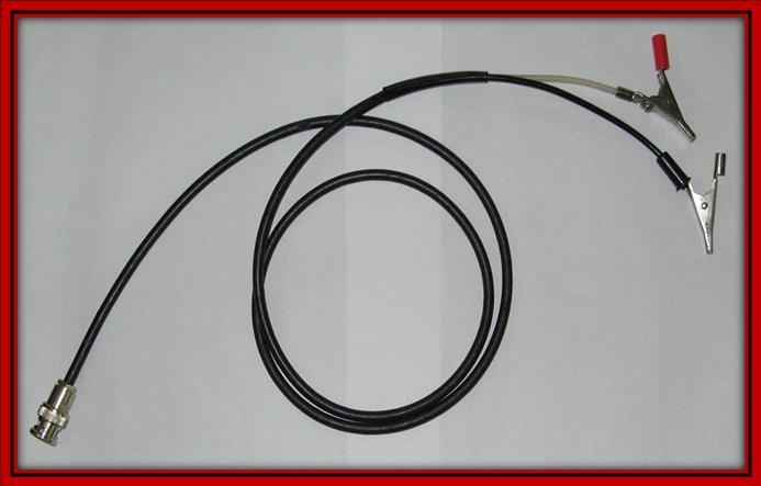
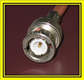
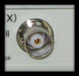
18 Some types of shielded cables with BNC connectors are shown as follows a) b) c) d) 18

19 Figure: a) BNC to BNC connector b) BNC to crocodile clip connector c) Male BNC connector and d) Female BNC connector (2) Measurement of Voltage, Current, Frequency and Time-period Figure: Vertical controls in a typical CRO In order to view any waveform the input signal is fed to either of the Y-plates CH1 or CH2 of the CRO. The time-base automatically latches onto the input signal. Under DUAL mode in a dualtrace CRO two different signals can simultaneously be compared on the same screen by providing inputs to both CH1 and CH2 Measurement of AC / DC level of the input signal - Choose Channel 1 or 2 (CH1, CH2) and feed input signal to them (Y-plates). Select AC or DC from AC-GND-DC switch. Adjust VOLTS/DIV and TIME/DIV knobs for optimal signal setting. Lock the VARIABLE knob at CAL 19
20 DC level measurement - Keep the switch first at GND (reference level) and then at DC. Measure the vertical distance between reference level to the point to be measured DC level = Vertical Distance (divisions) X VOLTS/DIV setting Measurement of peak-to-peak voltage (Vpp) - Apply input signal to one of the Y-plates, set the AC-GND-DC to AC, adjust VOLTS/DIV and TIME/DIV for optimal display Using horizontal position control, allow the first and the second points to coincide with the vertical graduated line one after another. Measure the vertical distance. Vpp = Vertical distance (divisions) X VOLTS/DIV setting For viewing two waveforms simultaneously feed input signals to both CH1 and CH2 and press both the buttons (DUAL mode) Measurement of time-period and hence frequency Time-period between two points on a signal is measured from the product of TIME/DIV value and horizontal distance between them (X-axis) Feed the signal, choose AC from AC-GND-DC switch, adjust VOLTS/DIV and TIME/DIV for optimal signal. Lock VARIABLE control to CAL. Keeping one point as reference use horizontal position to make the second point intersect any vertical graduation line. Measure the horizontal distance between the two points. 20
21 Time-period = Horizontal distance (divisions) X TIME/DIV setting Points to ponder: Frequently asked questions (FAQ) Q: Why two different CROs cannot be used for seeing the phase difference between tow signals? A: Despite keeping all calibrations same on both the CROs the time-base and trigger signals can never be made the same in two different CROs Q: There is only one electron gun in the dual-trace CRO, however it is able to show two waveforms at any given time. A: There are two methods that are undertaken in analog CROs to overcome this problem a) the electron beam is shared alternately between the two vertical channel inputs and b) fast switching between the two inputs is achieved. In analog 2 - channel CRT based CROs there is a function button named ALT/CHOP at the front interface wherein only one of them is in operation at a given time. At each application of trigger (TRIG), ALT button causes the electron beam to alternate between the two input channels (Y1 Y1 and Y2 Y2) and so for high frequency signals it is preferred choice. While under CHOP mode rapid switching between the two inputs is undertaken and hence it is suitable for low frequency signals. In both the cases the trigger signal has to be robust and reproducible. Q: Is a dual-beam CRO better than dual-trace CRO for measuring phase difference between two signals? 21
22 A: Dual-beam CROs are way too expensive because of the presence of two separate electron gun assemblies. Also again unlike the dual-trace CRO the time-base and trigger values of the two separate electron beams in the dual-beam CROs can never be made the same. Time-Base control knob Screen Vertical Movement CH1 Horizontal Movement Volts/ Div CH1 Signal input BNC CH1 AC-GND-DC switch 22
CHAPTER 4 OSCILLOSCOPES
 CHAPTER 4 OSCILLOSCOPES 4.1 Introduction The cathode ray oscilloscope generally referred to as the oscilloscope, is probably the most versatile electrical measuring instrument available. Some of electrical
The Cathode Ray Tube
 Lesson 2 The Cathode Ray Tube The Cathode Ray Oscilloscope Cathode Ray Oscilloscope Controls Uses of C.R.O. Electric Flux Electric Flux Through a Sphere Gauss s Law The Cathode Ray Tube Example 7 on an
CATHODE-RAY OSCILLOSCOPE (CRO)
") CATHODE-RAY OSCILLOSCOPE (CRO) I N T R O D U C T I O N : The cathode-ray oscilloscope (CRO) is a multipurpose display instrument used for the observation, measurement, and analysis of waveforms by plotting
CATHODE-RAY OSCILLOSCOPE (CRO) I N T R O D U C T I O N : The cathode-ray oscilloscope (CRO) is a multipurpose display instrument used for the observation, measurement, and analysis of waveforms by plotting
OSCILLOSCOPE AND DIGITAL MULTIMETER
 Exp. No #0 OSCILLOSCOPE AND DIGITAL MULTIMETER Date: OBJECTIVE The purpose of the experiment is to understand the operation of cathode ray oscilloscope (CRO) and to become familiar with its usage. Also
CATHODE RAY OSCILLOSCOPE. Basic block diagrams Principle of operation Measurement of voltage, current and frequency
 CATHODE RAY OSCILLOSCOPE Basic block diagrams Principle of operation Measurement of voltage, current and frequency 103 INTRODUCTION: The cathode-ray oscilloscope (CRO) is a multipurpose display instrument
Electrical and Electronic Laboratory Faculty of Engineering Chulalongkorn University. Cathode-Ray Oscilloscope (CRO)
") 2141274 Electrical and Electronic Laboratory Faculty of Engineering Chulalongkorn University Cathode-Ray Oscilloscope (CRO) Objectives You will be able to use an oscilloscope to measure voltage, frequency
2141274 Electrical and Electronic Laboratory Faculty of Engineering Chulalongkorn University Cathode-Ray Oscilloscope (CRO) Objectives You will be able to use an oscilloscope to measure voltage, frequency
CHAPTER 3 OSCILLOSCOPES AND SIGNAL GENERATOR
 CHAPTER 3 OSCILLOSCOPES AND SIGNAL GENERATOR OSCILLOSCOPE 3.1 Introduction The cathode ray oscilloscope (CRO) provides a visual presentation of any waveform applied to the input terminal. The oscilloscope
Elements of a Television System
 1 Elements of a Television System 1 Elements of a Television System The fundamental aim of a television system is to extend the sense of sight beyond its natural limits, along with the sound associated
Using an oscilloscope - The Hameg 203-6
 Using an oscilloscope - The Hameg 203-6 What does an oscilloscope do? Setting up How does an oscilloscope work? Other oscilloscope controls Connecting a function generator Microphones audio signals and
CATHODE RAY OSCILLOSCOPE (CRO)
") CATHODE RAY OSCILLOSCOPE (CRO) 4.6 (a) Cathode rays CORE Describe the production and detection of cathode rays Describe their deflection in electric fields State that the particles emitted in thermionic
CATHODE RAY OSCILLOSCOPE (CRO) 4.6 (a) Cathode rays CORE Describe the production and detection of cathode rays Describe their deflection in electric fields State that the particles emitted in thermionic
RICHLAND COLLEGE School of Engineering Business & Technology Rev. 0 W. Slonecker Rev. 1 (8/26/2012) J. Bradbury
 J. Bradbury") RICHLAND COLLEGE School of Engineering Business & Technology Rev. 0 W. Slonecker Rev. 1 (8/26/2012) J. Bradbury INTC 1307 Instrumentation Test Equipment Teaching Unit 8 Oscilloscopes Unit 8: Oscilloscopes
RICHLAND COLLEGE School of Engineering Business & Technology Rev. 0 W. Slonecker Rev. 1 (8/26/2012) J. Bradbury INTC 1307 Instrumentation Test Equipment Teaching Unit 8 Oscilloscopes Unit 8: Oscilloscopes
University of Utah Electrical & Computer Engineering Department ECE1050/1060 Oscilloscope
 University of Utah Electrical & Computer Engineering Department ECE1050/1060 Oscilloscope Name:, A. Stolp, 2/2/00 rev, 9/15/03 NOTE: This is a fill-in-the-blanks lab. No notebook is required. You are encouraged
Presented by: Amany Mohamed Yara Naguib May Mohamed Sara Mahmoud Maha Ali. Supervised by: Dr.Mohamed Abd El Ghany
 Presented by: Amany Mohamed Yara Naguib May Mohamed Sara Mahmoud Maha Ali Supervised by: Dr.Mohamed Abd El Ghany Analogue Terrestrial TV. No satellite Transmission Digital Satellite TV. Uses satellite
THE OPERATION OF A CATHODE RAY TUBE
 THE OPERATION OF A CATHODE RAY TUBE OBJECT: To acquaint the student with the operation of a cathode ray tube, and to study the effect of varying potential differences on accelerated electrons. THEORY:
S op o e p C on o t n rol o s L arni n n i g n g O bj b e j ctiv i e v s
 ET 150 Scope Controls Learning Objectives In this lesson you will: learn the location and function of oscilloscope controls. see block diagrams of analog and digital oscilloscopes. see how different input
THE OPERATION OF A CATHODE RAY TUBE
 THE OPERATION OF A CATHODE RAY TUBE OBJECT: To acquaint the student with the operation of a cathode ray tube, and to study the effect of varying potential differences on accelerated electrons. THEORY:
University of Utah Electrical Engineering Department EE1050/1060 Oscilloscope. Name:, Lab TA:
 University of Utah Electrical Engineering Department EE1050/1060 Oscilloscope Name:, Lab TA: A. Stolp, 2/2/00 rev, 9/14/00 NOTE: This is a fill-in-the-blanks lab. No notebook is required. You are encouraged
INSTRUMENT CATHODE-RAY TUBE
 Instrument cathode-ray tube D14-363GY/123 INSTRUMENT CATHODE-RAY TUBE mono accelerator 14 cm diagonal rectangular flat face internal graticule low power quick heating cathode high brightness, long-life
INSTRUMENT CATHODE-RAY TUBE
 INSTRUMENT CATHODE-RAY TUBE 14 cm diagonal rectangular flat face domed mesh post-deflection acceleration improved spot quality for character readout high precision by internal permanent magnetic correction
These are used for producing a narrow and sharply focus beam of electrons.
 CATHOD RAY TUBE (CRT) A CRT is an electronic tube designed to display electrical data. The basic CRT consists of four major components. 1. Electron Gun 2. Focussing & Accelerating Anodes 3. Horizontal
Types of CRT Display Devices. DVST-Direct View Storage Tube
 Examples of Computer Graphics Devices: CRT, EGA(Enhanced Graphic Adapter)/CGA/VGA/SVGA monitors, plotters, data matrix, laser printers, Films, flat panel devices, Video Digitizers, scanners, LCD Panels,
2.2. VIDEO DISPLAY DEVICES
 Introduction to Computer Graphics (CS602) Lecture 02 Graphics Systems 2.1. Introduction of Graphics Systems With the massive development in the field of computer graphics a broad range of graphics hardware
Experiment 9A: Magnetism/The Oscilloscope
 Experiment 9A: Magnetism/The Oscilloscope (This lab s "write up" is integrated into the answer sheet. You don't need to attach a separate one.) Part I: Magnetism and Coils A. Obtain a neodymium magnet
4.9 BEAM BLANKING AND PULSING OPTIONS
 4.9 BEAM BLANKING AND PULSING OPTIONS Beam Blanker BNC DESCRIPTION OF BLANKER CONTROLS Beam Blanker assembly Electron Gun Controls Blanker BNC: An input BNC on one of the 1⅓ CF flanges on the Flange Multiplexer
Laser Beam Analyser Laser Diagnos c System. If you can measure it, you can control it!
 Laser Beam Analyser Laser Diagnos c System If you can measure it, you can control it! Introduc on to Laser Beam Analysis In industrial -, medical - and laboratory applications using CO 2 and YAG lasers,
Reading. Display Devices. Light Gathering. The human retina
 Reading Hear & Baker, Computer graphics (2 nd edition), Chapter 2: Video Display Devices, p. 36-48, Prentice Hall Display Devices Optional.E. Sutherland. Sketchpad: a man-machine graphics communication
Oscilloscope Guide Tektronix TDS3034B & TDS3052B
 Tektronix TDS3034B & TDS3052B Version 2008-Jan-1 Dept. of Electrical & Computer Engineering Portland State University Copyright 2008 Portland State University 1 Basic Information This guide provides basic
Burlington County College INSTRUCTION GUIDE. for the. Hewlett Packard. FUNCTION GENERATOR Model #33120A. and. Tektronix
 v1.2 Burlington County College INSTRUCTION GUIDE for the Hewlett Packard FUNCTION GENERATOR Model #33120A and Tektronix OSCILLOSCOPE Model #MSO2004B Summer 2014 Pg. 2 Scope-Gen Handout_pgs1-8_v1.2_SU14.doc
Computer Graphics Hardware
 Computer Graphics Hardware Kenneth H. Carpenter Department of Electrical and Computer Engineering Kansas State University January 26, 2001 - February 5, 2004 1 The CRT display The most commonly used type
PRACTICAL APPLICATIONS OF ELECTRONICS IN ANAESTHESIA. G. A. HAY Department of Medical Physics, University of Leeds
 Brit. J. Anaesth. (1955), 27, 622 PRACTICAL APPLICATIONS OF ELECTRONICS IN ANAESTHESIA 1 BY G. A. HAY Department of Medical Physics, University of Leeds PART I: BASIC PRINCIPLES IN the last twenty years
PTIK UNNES. Lecture 02. Conceptual Model for Computer Graphics and Graphics Hardware Issues
 E3024031 KOMPUTER GRAFIK E3024032 PRAKTIK KOMPUTER GRAFIK PTIK UNNES Lecture 02 Conceptual Model for Computer Graphics and Graphics Hardware Issues 2014 Learning Objectives After carefully listening this
CR7000. CRT Analyzer & Restorer. Easily Test And Restore CRTs With The Most Complete Tests Available For Added Profit And Security.
 CR7000 CRT Analyzer & Restorer Easily Test And Restore CRTs With The Most Complete Tests Available For Added Profit And Security. S1 New Demands From Higher Performance CRTs Require New Analyzing Techniques
Lecture 17 Microwave Tubes: Part I
 Basic Building Blocks of Microwave Engineering Prof. Amitabha Bhattacharya Department of Electronics and Communication Engineering Indian Institute of Technology, Kharagpur Lecture 17 Microwave Tubes:
SC24 Magnetic Field Cancelling System
 SPICER CONSULTING SYSTEM SC24 SC24 Magnetic Field Cancelling System Makes the ambient magnetic field OK for the electron microscope Adapts to field changes within 100 µs Touch screen intelligent user interface
OPERATING INSTRUCTIONS FOR SYLVANIA. Type I08 Cathode-Ray Oscilloscope. Sylvania Electric Products Inc. Industrial Apparatus. Emporium, Pennsylvania
 OPERATING INSTRUCTIONS FOR SYLVANIA Type I08 Cathode-Ray Oscilloscope Sylvania Electric Products Inc. Industrial Apparatus Plant Emporium, Pennsylvania OPERATING INSTRUCTIONS FOR Sylvania Type 08 Cathode-Ray
Display Systems. Viewing Images Rochester Institute of Technology
 Display Systems Viewing Images 1999 Rochester Institute of Technology In This Section... We will explore how display systems work. Cathode Ray Tube Television Computer Monitor Flat Panel Display Liquid
 THE OSCILLOSCOPE AND SPECTRUM ANALYZER http://www.infodotinc.com/neets/book16/71.htm Page 1 of 5 Order this information in Print Order this information on CD-ROM D Click here to make tpub.com your Home
Computer Graphics: Overview of Graphics Systems
 Computer Graphics: Overview of Graphics Systems By: A. H. Abdul Hafez Abdul.hafez@hku.edu.tr, 1 Outlines 1. Video Display Devices 2. Flat-panel displays 3. Video controller and Raster-Scan System 4. Coordinate
SC24 Magnetic Field Cancelling System
 SPICER CONSULTING SYSTEM SC24 SC24 Magnetic Field Cancelling System Makes the ambient magnetic field OK for the electron microscope Adapts to field changes within 100 µs Touch screen intelligent user interface
The Knowledge Bank at The Ohio State University. Ohio State Engineer
 The Knowledge Bank at The Ohio State University Ohio State Engineer Title: Creators: Principles of Electron Tubes Lamoreaux, Yvonne Issue Date: 1944-03 Publisher: Ohio State University, College of Engineering
Physics 123 Hints and Tips
 Physics 123 Hints and Tips Solderless Breadboards All of the analog labs and most of the digital labs will be built on the Proto-Board solderless breadboards. These provide three solderless breadboard
ECE 5765 Modern Communication Fall 2005, UMD Experiment 10: PRBS Messages, Eye Patterns & Noise Simulation using PRBS
 ECE 5765 Modern Communication Fall 2005, UMD Experiment 10: PRBS Messages, Eye Patterns & Noise Simulation using PRBS modules basic: SEQUENCE GENERATOR, TUNEABLE LPF, ADDER, BUFFER AMPLIFIER extra basic:
Display Technologies CMSC 435. Slides based on Dr. Luebke s slides
 Display Technologies CMSC 435 Slides based on Dr. Luebke s slides Recap: Transforms Basic 2D Transforms: Scaling, Shearing, Rotation, Reflection, Composition of 2D Transforms Basic 3D Transforms: Rotation,
Brown, A., Merkert, J., & Wilson, R. (2014). Build your own particle accelerator. Science in School, (30),
. Build your own particle accelerator. Science in School, (30),") Brown, A., Merkert, J., & Wilson, R. (2014). Build your own particle accelerator. Science in School, (30), 21-26. Publisher's PDF, also known as Version of record License (if available): CC BY-NC-SA Link
Brown, A., Merkert, J., & Wilson, R. (2014). Build your own particle accelerator. Science in School, (30), 21-26. Publisher's PDF, also known as Version of record License (if available): CC BY-NC-SA Link
ME EN 363 ELEMENTARY INSTRUMENTATION Lab: Basic Lab Instruments and Data Acquisition
 ME EN 363 ELEMENTARY INSTRUMENTATION Lab: Basic Lab Instruments and Data Acquisition INTRODUCTION Many sensors produce continuous voltage signals. In this lab, you will learn about some common methods
SERVICING TELEVISION VOLUME 2 G. N. PATCHETT LONDON: NORMAN PRICE (PUBLISHERS) LTD. The Cathode Ray Tube. Sawtooth Current Generators
 LTD. The Cathode Ray Tube. Sawtooth Current Generators") m 3 TELEVISION SERVICING VOLUME 2 The Cathode Ray Tube Synchronizing Separators Timebases Field Output Stage Line Output Stage Sawtooth Current Generators G. N. PATCHETT B.Sc. (Eng.)., Ph.D., C. Eng.,
m 3 TELEVISION SERVICING VOLUME 2 The Cathode Ray Tube Synchronizing Separators Timebases Field Output Stage Line Output Stage Sawtooth Current Generators G. N. PATCHETT B.Sc. (Eng.)., Ph.D., C. Eng.,
Electrical & Electronic Measurements: Class Notes (15EE36) Module-5. Display Devices
 Module-5. Display Devices") Module-5 Display Devices Syllabus: Introduction Character formats Segment displays Dot matrix displays Bar graph displays Cathode ray tubes Light emitting diodes Liquid crystal displays Nixies Incandescent
Module-5 Display Devices Syllabus: Introduction Character formats Segment displays Dot matrix displays Bar graph displays Cathode ray tubes Light emitting diodes Liquid crystal displays Nixies Incandescent
Overview of All Pixel Circuits for Active Matrix Organic Light Emitting Diode (AMOLED)
") Chapter 2 Overview of All Pixel Circuits for Active Matrix Organic Light Emitting Diode (AMOLED) ---------------------------------------------------------------------------------------------------------------
Chapter 2 Overview of All Pixel Circuits for Active Matrix Organic Light Emitting Diode (AMOLED) ---------------------------------------------------------------------------------------------------------------
Reading 21 ELECTRON TUBES
 Reading 21 Ron Bertrand VK2DQ http://www.radioelectronicschool.com ELECTRON TUBES One of the most significant developments of the early twentieth century was the invention of the electron tube. The British
THE CATHODE -RAY OSCILLOSCOPE
 THE CATHODE -RAY OSCILLOSCOPE %ssok RRT -20 2533 N. Ashland Ave., Chicago 14, Illinois Radio Reception and Transmission LESSON RRT -20 THE CATHODE -RAY OSCILLOSCOPE CHRONOLOGICAL HISTORY OF RADIO AND
Display Devices & its Interfacing
 Display Devices & its Interfacing 3 Display systems are available in various technologies such as i) Cathode ray tubes (CRTs), ii) Liquid crystal displays (LCDs), iii) Plasma displays, and iv) Light emitting
Sep 09, APPLICATION NOTE 1193 Electronic Displays Comparison
 Sep 09, 2002 APPLICATION NOTE 1193 Electronic s Comparison Abstract: This note compares advantages and disadvantages of Cathode Ray Tubes, Electro-Luminescent, Flip- Dot, Incandescent Light Bulbs, Liquid
B. TECH. VI SEM. I MID TERM EXAMINATION 2018
 B. TECH. VI SEM. I MID TERM EXAMINATION 2018 BRANCH : COMPUTER SCIENCE ENGINEERING ( CSE ) SUBJECT : 6CS4A COMPUTER GRAPHICS & MULTIMEDIA TECHNIQUES Q 1. Write down mid point ellipse drawing algorithm.
PAST EXAM PAPER & MEMO N3 ABOUT THE QUESTION PAPERS:
 EKURHULENI TECH COLLEGE. No. 3 Mogale Square, Krugersdorp. Website: www. ekurhulenitech.co.za Email: info@ekurhulenitech.co.za TEL: 011 040 7343 CELL: 073 770 3028/060 715 4529 PAST EXAM PAPER & MEMO N3
CHAPTER 9. Actives Devices: Diodes, Transistors,Tubes
 CHAPTER 9 Actives Devices: Diodes, Transistors,Tubes 1 The electrodes of a semiconductor diode are known as anode and cathode. In a semiconductor diode, electrons flow from cathode to anode. In order for
UNIT-3 Part A. 2. What is radio sonde? [ N/D-16]
![UNIT-3 Part A. 2. What is radio sonde? [ N/D-16]](/thumbs/88/116973079.jpg "UNIT-3 Part A. 2. What is radio sonde? [ N/D-16]") UNIT-3 Part A 1. What is CFAR loss? [ N/D-16] Constant false alarm rate (CFAR) is a property of threshold or gain control devices that maintain an approximately constant rate of false target detections
UNIT-3 Part A 1. What is CFAR loss? [ N/D-16] Constant false alarm rate (CFAR) is a property of threshold or gain control devices that maintain an approximately constant rate of false target detections
decodes it along with the normal intensity signal, to determine how to modulate the three colour beams.
 Television Television as we know it today has hardly changed much since the 1950 s. Of course there have been improvements in stereo sound and closed captioning and better receivers for example but compared
Quick Start. RSHS1000 Series Handheld Digital Oscilloscope
 Quick Start RSHS1000 Series Handheld Digital Oscilloscope General Safety Summary Carefully read the following safety precautions to avoid personal injury and prevent damage to the instrument or any products
Choosing an Oscilloscope
 Choosing an Oscilloscope By Alan Lowne CEO Saelig Company (www.saelig.com) Post comments on this article at www.nutsvolts.com/ magazine/article/october2016_choosing-oscilloscopes. All sorts of questions
PRELIMINARY INFORMATION. Professional Signal Generation and Monitoring Options for RIFEforLIFE Research Equipment
 Integrated Component Options Professional Signal Generation and Monitoring Options for RIFEforLIFE Research Equipment PRELIMINARY INFORMATION SquareGENpro is the latest and most versatile of the frequency
A dedicated data acquisition system for ion velocity measurements of laser produced plasmas
 A dedicated data acquisition system for ion velocity measurements of laser produced plasmas N Sreedhar, S Nigam, Y B S R Prasad, V K Senecha & C P Navathe Laser Plasma Division, Centre for Advanced Technology,
Monitor QA Management i model
 Monitor QA Management i model 1/10 Monitor QA Management i model Table of Contents 1. Preface ------------------------------------------------------------------------------------------------------- 3 2.
An Efficient SOC approach to Design CRT controller on CPLD s
 A Monthly Peer Reviewed Open Access International e-journal An Efficient SOC approach to Design CRT controller on CPLD s Abstract: Sudheer Kumar Marsakatla M.tech Student, Department of ECE, ACE Engineering
Standby...For the Truth
 Innovation. Amplified. Chapter 6 Standby...For the Truth by Hartley Peavey Standby for the Truth Incredibly, very few modern technicians (and even fewer players) understand why so-called standby switches
A History of the Analog Cathode Ray Oscilloscope
 1 A History of the Analog Cathode Ray Oscilloscope by OLIVER DALTON and LIONEL KREPS CONTENTS 1.Introduction 3 Cathode Ray Oscilloscope definition 3 A History of the Cathode Ray Oscilloscope 3 2 Chapter
BTV Tuesday 21 November 2006
 Test Review Test from last Thursday. Biggest sellers of converters are HD to composite. All of these monitors in the studio are composite.. Identify the only portion of the vertical blanking interval waveform
Computer Graphics : Unit - I
 Computer Graphics Unit 1 Introduction: Computer Graphics it is a set of tools to create, manipulate and interact with pictures. Data is visualized through geometric shapes, colors and textures. Video Display
Light Emitting Diodes (LEDs)
") Light Emitting Diodes (LEDs) Example: Circuit symbol: Function LEDs emit light when an electric current passes through them. Connecting and soldering LEDs must be connected the correct way round, the diagram
Light Emitting Diodes (LEDs) Example: Circuit symbol: Function LEDs emit light when an electric current passes through them. Connecting and soldering LEDs must be connected the correct way round, the diagram
THERMIONIC GUN CATHODE-GRID ASSEMBLY TEST PROCEDURE
 SLACINJECTOR-PROC-001 Draft 4 Rev. 0 31 Oct 2007 THERMIONIC GUN CATHODE-GRID ASSEMBLY TEST PROCEDURE 1. INTRODUCTION. The thermionic gun at the injector in Sector 0 (CID) was developed for SLC in the early
NanoGiant Oscilloscope/Function-Generator Program. Getting Started
 Getting Started Page 1 of 17 NanoGiant Oscilloscope/Function-Generator Program Getting Started This NanoGiant Oscilloscope program gives you a small impression of the capabilities of the NanoGiant multi-purpose
INSTRUCTION GUIDE. for the. Keysight (formally Agilent; Hewlett-Packard) Model #33509B. and. Tektronix. Fall 2017
 Model #33509B. and. Tektronix. Fall 2017") v3 INSTRUCTION GUIDE for the Keysight (formally Agilent; Hewlett-Packard) WAVEFORM GENERATOR Model #33509B 33500 Series and Tektronix OSCILLOSCOPE Model #MSO2004B Fall 2017 Pg. 2 Scope-Gen Handout_part
v3 INSTRUCTION GUIDE for the Keysight (formally Agilent; Hewlett-Packard) WAVEFORM GENERATOR Model #33509B 33500 Series and Tektronix OSCILLOSCOPE Model #MSO2004B Fall 2017 Pg. 2 Scope-Gen Handout_part
CMPE 466 COMPUTER GRAPHICS
 1 CMPE 466 COMPUTER GRAPHICS Chapter 2 Computer Graphics Hardware Instructor: D. Arifler Material based on - Computer Graphics with OpenGL, Fourth Edition by Donald Hearn, M. Pauline Baker, and Warren
Reading. Displays and framebuffers. Modern graphics systems. History. Required. Angel, section 1.2, chapter 2 through 2.5. Related
 Reading Required Angel, section 1.2, chapter 2 through 2.5 Related Displays and framebuffers Hearn & Baker, Chapter 2, Overview of Graphics Systems OpenGL Programming Guide (the red book ): First four
3. Displays and framebuffers
 3. Displays and framebuffers 1 Reading Required Angel, pp.19-31. Hearn & Baker, pp. 36-38, 154-157. Optional Foley et al., sections 1.5, 4.2-4.5 I.E. Sutherland. Sketchpad: a man-machine graphics communication
Displays. History. Cathode ray tubes (CRTs) Modern graphics systems. CSE 457, Autumn 2003 Graphics. » Whirlwind Computer - MIT, 1950
 Modern graphics systems. CSE 457, Autumn 2003 Graphics. » Whirlwind Computer - MIT, 1950") History Displays CSE 457, Autumn 2003 Graphics http://www.cs.washington.edu/education/courses/457/03au/» Whirlwind Computer - MIT, 1950 CRT display» SAGE air-defense system - middle 1950 s Whirlwind II
History Displays CSE 457, Autumn 2003 Graphics http://www.cs.washington.edu/education/courses/457/03au/» Whirlwind Computer - MIT, 1950 CRT display» SAGE air-defense system - middle 1950 s Whirlwind II
Agilent DSO5014A Oscilloscope Tutorial
 Contents UNIVERSITY OF CALIFORNIA AT BERKELEY College of Engineering Department of Electrical Engineering and Computer Sciences EE105 Lab Experiments Agilent DSO5014A Oscilloscope Tutorial 1 Introduction
L14 - Video. L14: Spring 2005 Introductory Digital Systems Laboratory
 L14 - Video Slides 2-10 courtesy of Tayo Akinwande Take the graduate course, 6.973 consult Prof. Akinwande Some modifications of these slides by D. E. Troxel 1 How Do Displays Work? Electronic display
INSTRUCTION MANUAL Model 2522C. 20 MHz DIGITAL STORAGE/ANALOG OSCILLOSCOPE
 INSTRUCTION MANUAL Model 2522C 20 MHz DIGITAL STORAGE/ANALOG OSCILLOSCOPE TEST INSTRUMENT SAFETY WARNING Normal use of test equipment exposes you to a certain amount of danger from electrical shock because
Teltron Delection Tube D
 Teltron Delection Tube D 1011119 Overview The electron-beam deflection tube is intended for investigating the deflection of electron beams in electrical and magnetic fields. It can be used to estimate
Activity P32: Variation of Light Intensity (Light Sensor)
") Activity P32: Variation of Light Intensity (Light Sensor) Concept DataStudio ScienceWorkshop (Mac) ScienceWorkshop (Win) Illuminance P32 Vary Light.DS P54 Light Bulb Intensity P54_BULB.SWS Equipment Needed
Activity P32: Variation of Light Intensity (Light Sensor) Concept DataStudio ScienceWorkshop (Mac) ScienceWorkshop (Win) Illuminance P32 Vary Light.DS P54 Light Bulb Intensity P54_BULB.SWS Equipment Needed
AMEK SYSTEM 9098 DUAL MIC AMPLIFIER (DMA) by RUPERT NEVE the Designer
 by RUPERT NEVE the Designer") AMEK SYSTEM 9098 DUAL MIC AMPLIFIER (DMA) by RUPERT NEVE the Designer If you are thinking about buying a high-quality two-channel microphone amplifier, the Amek System 9098 Dual Mic Amplifier (based on
AMEK SYSTEM 9098 DUAL MIC AMPLIFIER (DMA) by RUPERT NEVE the Designer If you are thinking about buying a high-quality two-channel microphone amplifier, the Amek System 9098 Dual Mic Amplifier (based on
Beginners How to Test DSO138mini
 Beginners How to Test DSO138mini You have finished assembling your DSO138mini kit. You may be anxious to see it works. But you might not be familiar with oscilloscope and you could encounter unexpected
UNIT IV- STORAGE AND DISPLAY DEVICES
 UNIT IV- STORAGE AND DISPLAY DEVICES OBJECTIVES: We shall learn Classification Of Recorders Magnetic disk and tape Recorders, digital plotters and printers Introduction: It is usually required to have
Monitor and Display Adapters UNIT 4
 Monitor and Display Adapters UNIT 4 TOPIC TO BE COVERED: 4.1: video Basics(CRT Parameters) 4.2: VGA monitors 4.3: Digital Display Technology- Thin Film Displays, Liquid Crystal Displays, Plasma Displays
3B SCIENTIFIC PHYSICS
 B SCIENTIFIC PHYSICS Triode S 11 Instruction sheet 1/15 ALF 1 5 7 1 Guide pin Connection pins Cathode plate Heater filament 5 Grid Anode 7 -mm plug for connecting anode 1. Safety instructions Hot cathode
Lecture Flat Panel Display Devices
 Lecture 1 6.976 Flat Panel Display Devices Outline Overview of 6.976 Overview Flat Panel Display Devices Course website http://hackman.mit.edu Reading Assignment: Article by Alt and Noda, IBM Journal of
DEPARTMENT OF THE ARMY TECHNICAL BULLETIN CALIBRATION PROCEDURE FOR AUTOMATIC VIDEO CORRECTOR TEKTRONIX, MODEL 1440 (NSN )
") DEPARTMENT OF THE ARMY TECHNICAL BULLETIN TB 11-5820-861-35 CALIBRATION PROCEDURE FOR AUTOMATIC VIDEO CORRECTOR TEKTRONIX, MODEL 1440 (NSN 5820-00-570-1978) Headquarters, Department of the Army, Washington,
DEPARTMENT OF THE ARMY TECHNICAL BULLETIN TB 11-5820-861-35 CALIBRATION PROCEDURE FOR AUTOMATIC VIDEO CORRECTOR TEKTRONIX, MODEL 1440 (NSN 5820-00-570-1978) Headquarters, Department of the Army, Washington,
Brief Description of Circuit Functions. The brief ckt. description of V20 107E5 17 Monitor
 Exhibit 4 Brief Description of Circuit Functions The brief ckt. description of V20 107E5 17 Monitor 0. Functional Block Diagram 1. General Description 2. Description of Circuit Diagram A. Power Supply
Synthesized Clock Generator
 Synthesized Clock Generator CG635 DC to 2.05 GHz low-jitter clock generator Clocks from DC to 2.05 GHz Random jitter
Dan Schuster Arusha Technical College March 4, 2010
 Television Theory Of Operation Dan Schuster Arusha Technical College March 4, 2010 My TV Background 34 years in Automation and Image Electronics MS in Electrical and Computer Engineering Designed Television
Part 1: Introduction to Computer Graphics
 Part 1: Introduction to Computer Graphics 1. Define computer graphics? The branch of science and technology concerned with methods and techniques for converting data to or from visual presentation using
v1.0.0 January AlphaLab, Inc. All rights reserved. TriField EMF Meter Owner s Manual
 v1.0.0 January 2018 2018 AlphaLab, Inc. All rights reserved. TriField EMF Meter Owner s Manual TABLE OF CONTENTS Overview... 1 Introduction... 1 Features... 1 Applications... 1 Using the TriField EMF Meter...
Design and Simulation of High Power RF Modulated Triode Electron Gun. A. Poursaleh
 Design and Simulation of High Power RF Modulated Triode Electron Gun A. Poursaleh National Academy of Sciences of Armenia, Institute of Radio Physics & Electronics, Yerevan, Armenia poursaleh83@yahoo.com
What is sync? Why is sync important? How can sync signals be compromised within an A/V system?... 3
 Table of Contents What is sync?... 2 Why is sync important?... 2 How can sync signals be compromised within an A/V system?... 3 What is ADSP?... 3 What does ADSP technology do for sync signals?... 4 Which
Reading. 1. Displays and framebuffers. History. Modern graphics systems. Required
 Reading Required 1. Displays and s Angel, pp.19-31. Hearn & Baker, pp. 36-38, 154-157. OpenGL Programming Guide (available online): First four sections of chapter 2 First section of chapter 6 Optional
Application Note [AN-007] LCD Backlighting Technologies and Configurations
![Application Note [AN-007] LCD Backlighting Technologies and Configurations](/thumbs/81/83266365.jpg "Application Note [AN-007] LCD Backlighting Technologies and Configurations") Application Note [AN-007] LCD Backlighting Technologies Introduction Liquid Crystal Displays (LCDs) are not emissive i.e. they do not generate their own light. Transmissive and transflective displays require
Application Note [AN-007] LCD Backlighting Technologies Introduction Liquid Crystal Displays (LCDs) are not emissive i.e. they do not generate their own light. Transmissive and transflective displays require
Digital SWIR Scanning Laser Doppler Vibrometer
 Digital SWIR Scanning Laser Doppler Vibrometer Scan-Series OptoMET Scanning SWIR Laser Doppler Vibrometer (SLDV) is used for non-contact measurement, visualization and analysis of structural vibrations.
imso-104 Manual Revised August 5, 2011
 imso-104 Manual Revised August 5, 2011 Section 1 Getting Started SAFETY 1.10 Quickstart Guide 1.20 SAFETY 1.30 Compatibility 1.31 Hardware 1.32 Software Section 2 How it works 2.10 Menus 2.20 Analog Channel
SC26 Magnetic Field Cancelling System
 SPICER CONSULTING SYSTEM SC26 SC26 Magnetic Field Cancelling System Makes the ambient magnetic field OK for electron beam tools in 300 mm wafer fabs Real time, wideband cancelling from DC to > 9 khz fields
Working with a Tektronix TDS 3012B Oscilloscope EE 310: ELECTRONIC CIRCUIT DESIGN I
 Working with a Tektronix TDS 3012B Oscilloscope EE 310: ELECTRONIC CIRCUIT DESIGN I Prepared by: Kyle Botteon Questions? kyle.botteon@psu.edu 2 Background Information Recall that oscilloscopes (scopes)