Sequential circuits. Same input can produce different output. Logic circuit. William Sandqvist
|
|
|
- Gwendoline Hodges
- 6 years ago
- Views:
Transcription
1 Sequential circuits Same input can produce different output Logic circuit If the same input may produce different output signal, we have a sequential logic circuit. It must then have an internal memory that allows the output to be affected by both the current and previous inputs!
2 how can hardware remember? To remember something, then we must somehow store the information. One way is to store information is in the form of a charge on a Capacitance (DRAM) There are other possibilities...
3 "Latching" s 0 1 f 1 f 1 f f 0 0 f f f 0 1 If s = 1 the output f follows the input f 1. When s becomes s = 0 the circuit latches to the value f had in the moment before the transition s = 0. s = follow / latch


4 (Motor Protection ) R A Motor protection circuit braker is a relay with a latching contact. One need only press once for the engine to start. Will there be a power failure, so do not the engine start suddenly by itself when the power comes back - a good safety feature. The lights light up immediately, however - it is also good. S Relay
5 D C s D-Latch A D-latch is a MUX with feedback. When C = 0 the walue is latched. D C D-Latch 1D C1 D C C follow / latch 0 1 D D M latch D follow
6 NOR and NAND locking input signal Name Logic function - Gate Rule NAND. If any input is "0", so the output is "1" regardless of the value of the other input! NOR. If any input is "1", the output "0" whatever the value of the other input!
7 SR-latch with NOR-gates =1 For a NOR gate "1" is a "locking" input - if any input is "1" it does not matter what input value any other input has - the output will then always "0". =0 It is therefore enough with a short pulse "1" on S for the circuit to keep = 1. A short pulse "1" on R then gives = 0.
8 SR-latch R a S R a b S (a) Circuit As long as one avoids the input signal S = R = 1 (= forbidden input combination), the outputs a and b will be each other's inverses. One can then use the symbol to the right. b (b) Truth table S R 0/1 1/0 (no change) SR-Latch S R Forbidden input S=R=1 a b If one takes signals from latches, thus inverses are always available!?
9 SR-latch with NAND-gates S R S R S R latch S? R For NAND gates "0" is a latching input signal that forces the output to "1". A Latch with NAND gates have active low SET and RESET inputs. They may not be "0" both at the same time. S R M M

10 SR-Latch SR-Latch S S R R To the left we have an SR-latch with ropes - April 1-joke from Scientific American! Again there can be seen that you should not pull the SET and RESET ropes simultaneously!
11 ( Gated SR-Latch ) With two additional gates and a clock signal Clk you can control when the latch will get affected by the inputs S and R. When Clk = 0 there is no influence, then even S = R = 1 could be tolerated. S Clk R Forbidden combination Clk S R M M M M
12 D-latch A still better solution to the problem of the "forbidden" state is the D- latch. With an inverter one ensures that the S and R simply always has different values! The latch output follows the D input when Clk = 1 to lock the value when Clk = 0. This latch circuit has the same function as the MUX circuit with feedback. The difference is that this circuit has faster feedback. Moreover, we also have access to an inverted output. D Clk S = D R = D Clk = follow / latch! D Clk 1D C1 Clk D M M!
13 Two different D-latches D 1D D 1D Clk C1 Clk C1 Long feedback (~4T) Short feedback (~1T) D Clk MUX D Clk
14 Setup- & Hold-time D 1D Clk C1 D must be stable in this interval in order to guarante the function. D t hold t setup Clk t clk-to- follow latch
15 Register inverted signals A common way to design digital circuits is that the signal is taken via registers (= a set of latches or flipflops) to the combinatorial network inputs. D-latches "automatically" provides inverted signals at their outputs. That s why we in the calculation examples usually assumes that inverted signals are available.
16
17 Every other time? D 1D Clk C1 How do you construct a sequential circuit that will toggle its output 1/0 at every clockpulse, Clk? The circuit needs to remember it s previous value And change this to = D =. The latch has both "memory" and an inverted output - could it be used?
18 Not possible with a simple latch 1 Clk = follow / Clk D 1D C1 latch D = = D When Clk = 1 the output follows the input therefore the output changes 1/0 as quickly as possible! The circuit becomes an oscillator! Clk Later when Clk = 0 the output retains its value 1/0 after what it happened to be. (= Random Number Generator?)

19 Voting Help in parliament? 1 Clk D 1D C1 Clk Ja Nej
20 Clocked flip-flops Master-Slave flip-flop Master Slave The problem is that the simple latch is open to change right up until it will unlock its value. The solution is the clocked flip-flop consisting of several latches. One latch receives new data (Master) while another latch retaines the old data (Slave).
21 Timing diagram Master-Slave When Master do follow the Slave is latched. D Master D m D Slave s Clock Clk Clk When Slave do follow the Master is latched but then there is nothing to follow. Clock The output is only changed at the negative edge of the clock Edgetriggering symbol D m = s
22 Edgetriggered D-flipflop Another edge-triggered flip-flop consists of three latches. The data value is "copied" to the output just when the clock signal goes from 0 1. Positive edge 0 1 Negative edge 1 0
23 Latch or Flipflop? a) Latch follow/latch D D a b) Positive edgetriggered flipflop Clock Clk a c) Negative edgetriggered flipflop D b Clock b D a D c b c c
24 Every other time? Clk Now the "every other time circuit works just as planned! In general, for sequential circuits, edge-triggered flipflops are employed as the memory elements!

 Cost:")
25 Every second time with Impulse relay On-Off-On-Off Impulse relay Cost: 300: (2st D- flipflop) Cost: 5:- each

26 ( Contact Bounces ) There may be another threat to the "every other time" circuit, and it is that mechanical contacts bounces! You can try at the lab...
27 Clear and Preset D flip-flop contains three latches. Preset and Clear signals go directly to the latches and can "lock" these independent of the clock pulse. Preset and Clear are active low. Preset = 0 forces = 1, while Clear = 0 forces = 0. Preset = Clear = 1 allow the flipflop to perform as intended.

28 Reset-button Most digital systems needs to be started in a known state. This may mean that some flip-flops should be "1" while others will be "0". A reset function may need to be connected to either the Preset or Clear input on the flipflops. Preset and Clear are asynchronous inputs - the flipflop changes state instantly regardless of the clock pulse.
29 Synchronous Reset If the flip-flop lacks the Preset and Clear inputs, the reset is implemented with additional logic. Synchronous reset causes the flip-flop to reset to 0 at the next clock edge.
30 Asynchronous/Synchronous Reset Asynchronous reset Clear Clk Synchronous reset Clear Clk
31 Other common types of flip-flops (JK flip-flop is an SR flip-flop with "toggle" instead of the forbidden state) JK-flip-flop J K T-flip-flop (T=Toggle) Clk J K 0 0 M M Toggle Toggle (T-flip-flop is particularly suitable for counters ) T Clk T 0 M M 1 Toggle Toggle
32 Make a T-flip-flop out of a D-flip-flop D = hold T MUX D = toggle
33 Timing analysis It is possible to determine the maximum frequency in a sequential circuit by having information about Gate delays t logic Setup-time t su for the flip-flop Hold-time t h for the flip-flop Clock-to-output t c time
34 Setup- & Hold-time D must be stable within this range to ensure function D t hold t setup Clk t clk-to-
35 What is the maximum frequency? Gatedelays t logic = t NOT = 1.1 ns Setup-time t su = 0.6 ns Hold-time t h = 0.4 ns Clock-to-output t c = 1.0 ns < T = t su + max(t h, t c ) + t logic = 2.7 ns f = 1/T = 370 MHz
36 Shiftregister A shiftregister contains several flip-flops For each clock cycle a value will be shifted from left to right Many designs use shift registers and the values 4,..., 1 as input values to others Components,
37 Would not work with latches You can not build a shift register with latches. When C = 1 follow the data will "drain" through all latches...
38 Common types of shift registers Parallel-In/Parallel-Out (PIPO) Parallel-In/Serial-Out (PISO) Serial-In/Parallel-Out (SIPO) Serial-In/Serial-Out (SISO) Uses ueues, eg. First-In/First-Out (FIFO) Pattern recognizers
39
40 Counters A counter is a special type of sequential circuit that records the number of incoming clock pulses. Registration is usually done in the binary code. After a certain number of pulses the counter reaches its final state and then it starts from the beginning again. The number of states is the counter s module. The counter does not need to have any inputs except the clock pulses (which then can then be viewed as the input signal). Such sequential circuits are called autonomous.
41 Binary Code counting properties There are two different "rules" for constructing the binary code from the less significant bits. Example with binary code Toggle at CP when all previous bits =1 Toggle the bit at each CP Toggle the bit at every other CP Toggle the bit at every other every other CP Toggle the bit at every other every other every other CP
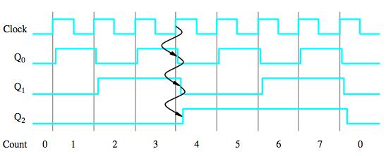
42 Toggle every other every other, every other every other, every other every other every other The counter is built of T-flip-flops, they all have T = 1 and "toggles" at clock pulses. The first flip-flop 0 "toggles" at each clockpulse. The next flip-flop 1 is clocked by the first flip-flop. It will only toggle for each other clockpulse. The third flip-flop 2 will toggle for each other each other clockpulse. According to the binary table, the counter will be counting in binary code. ( : ).
43 How is this counter counting?
44 Asynchronous counter


45 A counter circuit 32,768 khz 32,768 khz 74HC = Hz How to get one second you have to figure out yourself... 8 Hz
46 Toggle if all previous are 1 Carry chain A faster counter can be designed with parallel gates for the carry carry look ahead. The clock pulses go directly to all the flip-flops and therefore they change state at the same time. What flip-flop to turn on or not is controlled by the T- inputs. The first flip-flop has T = 1, and it toggles on every clock pulse. The rule is that a flip-flop should toggle if all previous flip-flops stands at "1". This condition is obtained from the AND gates in the so-called Carry chain and it is these gates that control the T-inputs. If you want to expand the counter it is done with a flipflop and an AND gate per bit.
47 Synchronous counter In a synchronous counter flip-flops clock inputs are connected to the same clock signal How does this counter count?

48 Synchronous counter = =
49 Maximum counting frequency? The critical path determines the maximum frequency! This is the longest combinational path from 0 through the two AND gates to the input of flip-flop that calculates 3 t logic is thus equivalent to the delay of two AND gates.
50 Asynchronous or Synchronous counter Asynchronous counter Synchronous counter The output signals are delayed more and more with every step The output signals have the same delay
51
52 VHDL for flip-flop and lathes Programable logic has embedded flip-flops.
53 VHDL for flip-flops and latches Programmable logic has embedded flipflops. How to write VHDL code that "tells" the compiler that you want to use them?
54 A D-latch in VHDL ENTITY D_Latch IS PORT(en : IN std_logic; d : IN std_logic; q : OUT std_logic); END ENTITY D_Latch; d Latch D q No else? ARCHITECTURE RTL OF D_Latch IS BEGIN PROCESS(en, d) BEGIN IF en = '1' THEN q <= d; END IF; END PROCESS; END ARCHITECTURE RTL; en Enable D 0 - M 1 D D
55 Latch as a process PROCESS(en, d) BEGIN IF en = '1' THEN q <= d; END IF; END PROCESS; Latches are generally considered to be bad from the synthesis point of view because they are not always testable. Therefore one avoids latches. (Programmable Logic has embedded flipflops with asynchronous Preset and Clear that you can use).
56 Flip-flop as a process d clk q PROCESS(clk) BEGIN IF rising_edge(clk) THEN q <= d; END IF; END PROCESS; Only one edge is allowed per process Instead of the function rising_edge(clk) you can write clk event and clk=1 The compiler will "understand" that this is a flip-flop and using any of the built-in flip-flops to implement the process.
57 With asynchronous RESET d clk clear_n Clear independent of clk q PROCESS(clk, clear_n) BEGIN IF clear_n = 0 THEN q <= 0 ; ELSE IF rising_edge(clk) THEN q <= d; END IF; END PROCESS;
58 With synchronous RESET clear_n d PROCESS(clk) BEGIN IF rising_edge(clk) THEN IF clear_n = 0 THEN q <= 0 ; ELSE q <= d; END IF; END PROCESS; clk q
59 Counters and other sequential circuits What does this "counter"? bcd: PROCESS(clk) BEGIN IF rising_edge(clk) THEN IF (count = 9) THEN count <= 0; ELSE count <= count+1; END IF; END IF; END PROCESS;
60
Logic Design. Flip Flops, Registers and Counters
 Logic Design Flip Flops, Registers and Counters Introduction Combinational circuits: value of each output depends only on the values of inputs Sequential Circuits: values of outputs depend on inputs and
YEDITEPE UNIVERSITY DEPARTMENT OF COMPUTER ENGINEERING. EXPERIMENT VIII: FLIP-FLOPS, COUNTERS 2014 Fall
 YEDITEPE UNIVERSITY DEPARTMENT OF COMPUTER ENGINEERING EXPERIMENT VIII: FLIP-FLOPS, COUNTERS 2014 Fall Objective: - Dealing with the operation of simple sequential devices. Learning invalid condition in
CHAPTER 6 COUNTERS & REGISTERS
 CHAPTER 6 COUNTERS & REGISTERS 6.1 Asynchronous Counter 6.2 Synchronous Counter 6.3 State Machine 6.4 Basic Shift Register 6.5 Serial In/Serial Out Shift Register 6.6 Serial In/Parallel Out Shift Register
RS flip-flop using NOR gate
 RS flip-flop using NOR gate Triggering and triggering methods Triggering : Applying train of pulses, to set or reset the memory cell is known as Triggering. Triggering methods:- There are basically two
Lecture 8: Sequential Logic
 Lecture 8: Sequential Logic Last lecture discussed how we can use digital electronics to do combinatorial logic we designed circuits that gave an immediate output when presented with a given set of inputs
SEQUENTIAL LOGIC. Satish Chandra Assistant Professor Department of Physics P P N College, Kanpur
 SEQUENTIAL LOGIC Satish Chandra Assistant Professor Department of Physics P P N College, Kanpur www.satish0402.weebly.com OSCILLATORS Oscillators is an amplifier which derives its input from output. Oscillators
Chapter 6. Flip-Flops and Simple Flip-Flop Applications
 Chapter 6 Flip-Flops and Simple Flip-Flop Applications Basic bistable element It is a circuit having two stable conditions (states). It can be used to store binary symbols. J. C. Huang, 2004 Digital Logic
LATCHES & FLIP-FLOP. Chapter 7
 LATCHES & FLIP-FLOP Chapter 7 INTRODUCTION Latch and flip flops are categorized as bistable devices which have two stable states,called SET and RESET. They can retain either of this states indefinitely
UNIT-3: SEQUENTIAL LOGIC CIRCUITS
 UNIT-3: SEQUENTIAL LOGIC CIRCUITS STRUCTURE 3. Objectives 3. Introduction 3.2 Sequential Logic Circuits 3.2. NAND Latch 3.2.2 RS Flip-Flop 3.2.3 D Flip-Flop 3.2.4 JK Flip-Flop 3.2.5 Edge Triggered RS Flip-Flop
Introduction. NAND Gate Latch. Digital Logic Design 1 FLIP-FLOP. Digital Logic Design 1
 2007 Introduction BK TP.HCM FLIP-FLOP So far we have seen Combinational Logic The output(s) depends only on the current values of the input variables Here we will look at Sequential Logic circuits The
EMT 125 Digital Electronic Principles I CHAPTER 6 : FLIP-FLOP
 EMT 125 Digital Electronic Principles I CHAPTER 6 : FLIP-FLOP 1 Chapter Overview Latches Gated Latches Edge-triggered flip-flops Master-slave flip-flops Flip-flop operating characteristics Flip-flop applications
D Latch (Transparent Latch)
") D Latch (Transparent Latch) -One way to eliminate the undesirable condition of the indeterminate state in the SR latch is to ensure that inputs S and R are never equal to 1 at the same time. This is done
D Latch (Transparent Latch) -One way to eliminate the undesirable condition of the indeterminate state in the SR latch is to ensure that inputs S and R are never equal to 1 at the same time. This is done
Universal Asynchronous Receiver- Transmitter (UART)
") Universal Asynchronous Receiver- Transmitter (UART) (UART) Block Diagram Four-Bit Bidirectional Shift Register Shift Register Counters Shift registers can form useful counters by recirculating a pattern
Universal Asynchronous Receiver- Transmitter (UART) (UART) Block Diagram Four-Bit Bidirectional Shift Register Shift Register Counters Shift registers can form useful counters by recirculating a pattern
RS flip-flop using NOR gate
 RS flip-flop using NOR gate Triggering and triggering methods Triggering : Applying train of pulses, to set or reset the memory cell is known as Triggering. Triggering methods:- There are basically two
Experiment 8 Introduction to Latches and Flip-Flops and registers
 Experiment 8 Introduction to Latches and Flip-Flops and registers Introduction: The logic circuits that have been used until now were combinational logic circuits since the output of the device depends
Rangkaian Sekuensial. Flip-flop
 Rangkaian Sekuensial Rangkaian Sekuensial Flip-flop Combinational versus Sequential Functions Logic functions are categorized as being either combinational (sometimes referred to as combinatorial) or sequential.
Sequential Logic Basics
 Sequential Logic Basics Unlike Combinational Logic circuits that change state depending upon the actual signals being applied to their inputs at that time, Sequential Logic circuits have some form of inherent
Name Of The Experiment: Sequential circuit design Latch, Flip-flop and Registers
 EEE 304 Experiment No. 07 Name Of The Experiment: Sequential circuit design Latch, Flip-flop and Registers Important: Submit your Prelab at the beginning of the lab. Prelab 1: Construct a S-R Latch and
Serial In/Serial Left/Serial Out Operation
 Shift Registers The need to storage binary data was discussed earlier. In digital circuits multi-bit data has to be stored temporarily until it is processed. A flip-flop is able to store a single binary
Introduction to Sequential Circuits
 Introduction to Sequential Circuits COE 202 Digital Logic Design Dr. Muhamed Mudawar King Fahd University of Petroleum and Minerals Presentation Outline Introduction to Sequential Circuits Synchronous
ELCT201: DIGITAL LOGIC DESIGN
 ELCT201: DIGITAL LOGIC DESIGN Dr. Eng. Haitham Omran, haitham.omran@guc.edu.eg Dr. Eng. Wassim Alexan, wassim.joseph@guc.edu.eg Lecture 7 Following the slides of Dr. Ahmed H. Madian محرم 1439 ه Winter
(CSC-3501) Lecture 7 (07 Feb 2008) Seung-Jong Park (Jay) CSC S.J. Park. Announcement
 Lecture 7 (07 Feb 2008) Seung-Jong Park (Jay) CSC S.J. Park. Announcement") Seung-Jong Park (Jay) http://www.csc.lsu.edu/~sjpark Computer Architecture (CSC-3501) Lecture 7 (07 Feb 2008) 1 Announcement 2 1 Combinational vs. Sequential Logic Combinational Logic Memoryless Outputs
Seung-Jong Park (Jay) http://www.csc.lsu.edu/~sjpark Computer Architecture (CSC-3501) Lecture 7 (07 Feb 2008) 1 Announcement 2 1 Combinational vs. Sequential Logic Combinational Logic Memoryless Outputs
ELCT201: DIGITAL LOGIC DESIGN
 ELCT201: DIGITAL LOGIC DESIGN Dr. Eng. Haitham Omran, haitham.omran@guc.edu.eg Dr. Eng. Wassim Alexan, wassim.joseph@guc.edu.eg Lecture 6 Following the slides of Dr. Ahmed H. Madian ذو الحجة 1438 ه Winter
Digital Logic Design Sequential Circuits. Dr. Basem ElHalawany
 Digital Logic Design Sequential Circuits Dr. Basem ElHalawany Combinational vs Sequential inputs X Combinational Circuits outputs Z A combinational circuit: At any time, outputs depends only on inputs
Asynchronous (Ripple) Counters
 Counters") Circuits for counting events are frequently used in computers and other digital systems. Since a counter circuit must remember its past states, it has to possess memory. The chapter about flip-flops introduced
Circuits for counting events are frequently used in computers and other digital systems. Since a counter circuit must remember its past states, it has to possess memory. The chapter about flip-flops introduced
Other Flip-Flops. Lecture 27 1
 Other Flip-Flops Other types of flip-flops can be constructed by using the D flip-flop and external logic. Two flip-flops less widely used in the design of digital systems are the JK and T flip-flops.
Digital Logic Design ENEE x. Lecture 19
 Digital Logic Design ENEE 244-010x Lecture 19 Announcements Homework 8 due on Monday, 11/23. Agenda Last time: Timing Considerations (6.3) Master-Slave Flip-Flops (6.4) This time: Edge-Triggered Flip-Flops
Chapter 4. Logic Design
 Chapter 4 Logic Design 4.1 Introduction. In previous Chapter we studied gates and combinational circuits, which made by gates (AND, OR, NOT etc.). That can be represented by circuit diagram, truth table
Counters
 Counters A counter is the most versatile and useful subsystems in the digital system. A counter driven by a clock can be used to count the number of clock cycles. Since clock pulses occur at known intervals,
Sequential Logic. E&CE 223 Digital Circuits and Systems (A. Kennings) Page 1
 Page 1") Sequential Logic E&CE 223 igital Circuits and Systems (A. Kennings) Page 1 Sequential Circuits Have considered only combinational circuits in which circuit outputs are determined entirely by current circuit
Sequential Logic E&CE 223 igital Circuits and Systems (A. Kennings) Page 1 Sequential Circuits Have considered only combinational circuits in which circuit outputs are determined entirely by current circuit
Chapter 7 Counters and Registers
 Chapter 7 Counters and Registers Chapter 7 Objectives Selected areas covered in this chapter: Operation & characteristics of synchronous and asynchronous counters. Analyzing and evaluating various types
Module -5 Sequential Logic Design
 Module -5 Sequential Logic Design 5.1. Motivation: In digital circuit theory, sequential logic is a type of logic circuit whose output depends not only on the present value of its input signals but on
IT T35 Digital system desigm y - ii /s - iii
 UNIT - III Sequential Logic I Sequential circuits: latches flip flops analysis of clocked sequential circuits state reduction and assignments Registers and Counters: Registers shift registers ripple counters
Unit 11. Latches and Flip-Flops
 Unit 11 Latches and Flip-Flops 1 Combinational Circuits A combinational circuit consists of logic gates whose outputs, at any time, are determined by combining the values of the inputs. For n input variables,
Registers and Counters
 Registers and Counters Clocked sequential circuit = F/Fs and combinational gates Register Group of flip-flops (share a common clock and capable of storing one bit of information) Consist of a group of
Flip-Flops and Sequential Circuit Design
 Flip-Flops and Sequential Circuit Design ECE 52 Summer 29 Reading ssignment Brown and Vranesic 7 Flip-Flops, Registers, Counters and a Simple Processor 7.5 T Flip-Flop 7.5. Configurable Flip-Flops 7.6
EET2411 DIGITAL ELECTRONICS
 5-8 Clocked D Flip-FlopFlop One data input. The output changes to the value of the input at either the positive going or negative going clock trigger. May be implemented with a J-K FF by tying the J input
MC9211 Computer Organization
 MC9211 Computer Organization Unit 2 : Combinational and Sequential Circuits Lesson2 : Sequential Circuits (KSB) (MCA) (2009-12/ODD) (2009-10/1 A&B) Coverage Lesson2 Outlines the formal procedures for the
DIGITAL SYSTEM FUNDAMENTALS (ECE421) DIGITAL ELECTRONICS FUNDAMENTAL (ECE422) COUNTERS
 DIGITAL ELECTRONICS FUNDAMENTAL (ECE422) COUNTERS") COURSE / CODE DIGITAL SYSTEM FUNDAMENTALS (ECE421) DIGITAL ELECTRONICS FUNDAMENTAL (ECE422) COUNTERS One common requirement in digital circuits is counting, both forward and backward. Digital clocks and
COURSE / CODE DIGITAL SYSTEM FUNDAMENTALS (ECE421) DIGITAL ELECTRONICS FUNDAMENTAL (ECE422) COUNTERS One common requirement in digital circuits is counting, both forward and backward. Digital clocks and
Unit 9 Latches and Flip-Flops. Dept. of Electrical and Computer Eng., NCTU 1
 Unit 9 Latches and Flip-Flops Dept. of Electrical and Computer Eng., NCTU 1 9.1 Introduction Dept. of Electrical and Computer Eng., NCTU 2 What is the characteristic of sequential circuits in contrast
MODULE 3. Combinational & Sequential logic
 MODULE 3 Combinational & Sequential logic Combinational Logic Introduction Logic circuit may be classified into two categories. Combinational logic circuits 2. Sequential logic circuits A combinational
Digital Fundamentals: A Systems Approach
 Digital Fundamentals: A Systems Approach Latches, Flip-Flops, and Timers Chapter 6 Traffic Signal Control Traffic Signal Control: State Diagram Traffic Signal Control: Block Diagram Traffic Signal Control:
DEPARTMENT OF ELECTRICAL &ELECTRONICS ENGINEERING DIGITAL DESIGN
 DEPARTMENT OF ELECTRICAL &ELECTRONICS ENGINEERING DIGITAL DESIGN Assoc. Prof. Dr. Burak Kelleci Spring 2018 OUTLINE Synchronous Logic Circuits Latch Flip-Flop Timing Counters Shift Register Synchronous
Sequential Digital Design. Laboratory Manual. Experiment #3. Flip Flop Storage Elements
 The Islamic University of Gaza Engineering Faculty Department of Computer Engineering Spring 2018 ECOM 2022 Khaleel I. Shaheen Sequential Digital Design Laboratory Manual Experiment #3 Flip Flop Storage
Flip-flop and Registers
 ECE 322 Digital Design with VHDL Flip-flop and Registers Lecture Textbook References n Sequential Logic Review Stephen Brown and Zvonko Vranesic, Fundamentals of Digital Logic with VHDL Design, 2 nd or
UNIT IV. Sequential circuit
 UNIT IV Sequential circuit Introduction In the previous session, we said that the output of a combinational circuit depends solely upon the input. The implication is that combinational circuits have no
INTRODUCTION TO SEQUENTIAL CIRCUITS
 NOTE: Explanation Refer Class Notes Digital Circuits(15EECC203) INTRODUCTION TO SEQUENTIAL CIRCUITS by Nagaraj Vannal, Asst.Professor, School of Electronics Engineering, K.L.E. Technological University,
Synchronous Sequential Logic
 Synchronous Sequential Logic -A Sequential Circuit consists of a combinational circuit to which storage elements are connected to form a feedback path. The storage elements are devices capable of storing
CPS311 Lecture: Sequential Circuits
 CPS311 Lecture: Sequential Circuits Last revised August 4, 2015 Objectives: 1. To introduce asynchronous and synchronous flip-flops (latches and pulsetriggered, plus asynchronous preset/clear) 2. To introduce
NH 67, Karur Trichy Highways, Puliyur C.F, Karur District UNIT-III SEQUENTIAL CIRCUITS
 NH 67, Karur Trichy Highways, Puliyur C.F, 639 114 Karur District DEPARTMENT OF ELETRONICS AND COMMUNICATION ENGINEERING COURSE NOTES SUBJECT: DIGITAL ELECTRONICS CLASS: II YEAR ECE SUBJECT CODE: EC2203
Solution to Digital Logic )What is the magnitude comparator? Design a logic circuit for 4 bit magnitude comparator and explain it,
What is the magnitude comparator? Design a logic circuit for 4 bit magnitude comparator and explain it,") Solution to Digital Logic -2067 Solution to digital logic 2067 1.)What is the magnitude comparator? Design a logic circuit for 4 bit magnitude comparator and explain it, A Magnitude comparator is a combinational
Solution to Digital Logic -2067 Solution to digital logic 2067 1.)What is the magnitude comparator? Design a logic circuit for 4 bit magnitude comparator and explain it, A Magnitude comparator is a combinational
HDL & High Level Synthesize (EEET 2035) Laboratory II Sequential Circuits with VHDL: DFF, Counter, TFF and Timer
 Laboratory II Sequential Circuits with VHDL: DFF, Counter, TFF and Timer") 1 P a g e HDL & High Level Synthesize (EEET 2035) Laboratory II Sequential Circuits with VHDL: DFF, Counter, TFF and Timer Objectives: Develop the behavioural style VHDL code for D-Flip Flop using gated,
1 P a g e HDL & High Level Synthesize (EEET 2035) Laboratory II Sequential Circuits with VHDL: DFF, Counter, TFF and Timer Objectives: Develop the behavioural style VHDL code for D-Flip Flop using gated,
CHAPTER 1 LATCHES & FLIP-FLOPS
 CHAPTER 1 LATCHES & FLIP-FLOPS 1 Outcome After learning this chapter, student should be able to; Recognize the difference between latches and flipflops Analyze the operation of the flip flop Draw the output
Registers and Counters
 Registers and Counters Clocked sequential circuit = F/Fs and combinational gates Register Group of flip-flops (share a common clock and capable of storing one bit of information) Consist of a group of
0 0/1 0/1 0/1 0/1 0/1 0/1 0/1 0/1 1 1 Stop bits. 11-bit Serial Data format
 Applications of Shift Registers The major application of a shift register is to convert between parallel and serial data. Shift registers are also used as keyboard encoders. The two applications of the
Chapter 11 Latches and Flip-Flops
 Chapter 11 Latches and Flip-Flops SKEE1223 igital Electronics Mun im/arif/izam FKE, Universiti Teknologi Malaysia ecember 8, 2015 Types of Logic Circuits Combinational logic: Output depends solely on the
Sequential Digital Design. Laboratory Manual. Experiment #7. Counters
 The Islamic University of Gaza Engineering Faculty Department of Computer Engineering Spring 2018 ECOM 2022 Khaleel I. Shaheen Sequential Digital Design Laboratory Manual Experiment #7 Counters Objectives
EE292: Fundamentals of ECE
 EE292: Fundamentals of ECE Fall 2012 TTh 10:00-11:15 SEB 1242 Lecture 23 121120 http://www.ee.unlv.edu/~b1morris/ee292/ 2 Outline Review Combinatorial Logic Sequential Logic 3 Combinatorial Logic Circuits
Vignana Bharathi Institute of Technology UNIT 4 DLD
 DLD UNIT IV Synchronous Sequential Circuits, Latches, Flip-flops, analysis of clocked sequential circuits, Registers, Shift registers, Ripple counters, Synchronous counters, other counters. Asynchronous
EKT 121/4 ELEKTRONIK DIGIT 1
 EKT 121/4 ELEKTRONIK DIGIT 1 Kolej Universiti Kejuruteraan Utara Malaysia Bistable Storage Devices and Related Devices Introduction Latches and flip-flops are the basic single-bit memory elements used
cascading flip-flops for proper operation clock skew Hardware description languages and sequential logic
 equential logic equential circuits simple circuits with feedback latches edge-triggered flip-flops Timing methodologies cascading flip-flops for proper operation clock skew Basic registers shift registers
More on Flip-Flops Digital Design and Computer Architecture: ARM Edition 2015 Chapter 3 <98> 98
 More on Flip-Flops Digital Design and Computer Architecture: ARM Edition 2015 Chapter 3 98 Review: Bit Storage SR latch S (set) Q R (reset) Level-sensitive SR latch S S1 C R R1 Q D C S R D latch Q
Objectives. Combinational logics Sequential logics Finite state machine Arithmetic circuits Datapath
 Objectives Combinational logics Sequential logics Finite state machine Arithmetic circuits Datapath In the previous chapters we have studied how to develop a specification from a given application, and
Sequential logic. Circuits with feedback. How to control feedback? Sequential circuits. Timing methodologies. Basic registers
 equential logic equential circuits simple circuits with feedback latches edge-triggered flip-flops Timing methodologies cascading flip-flops for proper operation clock skew Basic registers shift registers
Flip Flop. S-R Flip Flop. Sequential Circuits. Block diagram. Prepared by:- Anwar Bari
 Sequential Circuits The combinational circuit does not use any memory. Hence the previous state of input does not have any effect on the present state of the circuit. But sequential circuit has memory
DIGITAL SYSTEM FUNDAMENTALS (ECE421) DIGITAL ELECTRONICS FUNDAMENTAL (ECE422) LATCHES and FLIP-FLOPS
 DIGITAL ELECTRONICS FUNDAMENTAL (ECE422) LATCHES and FLIP-FLOPS") COURSE / CODE DIGITAL SYSTEM FUNDAMENTALS (ECE421) DIGITAL ELECTRONICS FUNDAMENTAL (ECE422) LATCHES and FLIP-FLOPS In the same way that logic gates are the building blocks of combinatorial circuits, latches
COURSE / CODE DIGITAL SYSTEM FUNDAMENTALS (ECE421) DIGITAL ELECTRONICS FUNDAMENTAL (ECE422) LATCHES and FLIP-FLOPS In the same way that logic gates are the building blocks of combinatorial circuits, latches
Chapter 8 Sequential Circuits
 Philadelphia University Faculty of Information Technology Department of Computer Science Computer Logic Design By 1 Chapter 8 Sequential Circuits 1 Classification of Combinational Logic 3 Sequential circuits
Logic and Computer Design Fundamentals. Chapter 7. Registers and Counters
 Logic and Computer Design Fundamentals Chapter 7 Registers and Counters Registers Register a collection of binary storage elements In theory, a register is sequential logic which can be defined by a state
EEE2135 Digital Logic Design Chapter 6. Latches/Flip-Flops and Registers/Counters 서강대학교 전자공학과
 EEE235 Digital Logic Design Chapter 6. Latches/Flip-Flops and Registers/Counters 서강대학교 전자공학과 . Delay and Latches ) Signal Storage a. as voltage level static memory b. as charges dynamic memory 2) Delays
ECE 263 Digital Systems, Fall 2015
 ECE 263 Digital Systems, Fall 2015 REVIEW: FINALS MEMORY ROM, PROM, EPROM, EEPROM, FLASH RAM, DRAM, SRAM Design of a memory cell 1. Draw circuits and write 2 differences and 2 similarities between DRAM
Switching Circuits & Logic Design
 Switching Circuits & Logic Design Jie-Hong oland Jiang 江介宏 Department of Electrical Engineering National Taiwan University Fall 22 Latches and Flip-Flops http://www3.niaid.nih.gov/topics/malaria/lifecycle.htm
CHAPTER 4: Logic Circuits
 CHAPTER 4: Logic Circuits II. Sequential Circuits Combinational circuits o The outputs depend only on the current input values o It uses only logic gates, decoders, multiplexers, ALUs Sequential circuits
Modeling Latches and Flip-flops
 Lab Workbook Introduction Sequential circuits are digital circuits in which the output depends not only on the present input (like combinatorial circuits), but also on the past sequence of inputs. In effect,
Introduction to Microprocessor & Digital Logic
 ME262 Introduction to Microprocessor & Digital Logic (Sequential Logic) Summer 2 Sequential Logic Definition The output(s) of a sequential circuit depends d on the current and past states of the inputs,
ELE2120 Digital Circuits and Systems. Tutorial Note 7
 ELE2120 Digital Circuits and Systems Tutorial Note 7 Outline 1. Sequential Circuit 2. Gated SR Latch 3. Gated D-latch 4. Edge-Triggered D Flip-Flop 5. Asynchronous and Synchronous reset Sequential Circuit
Computer Science 324 Computer Architecture Mount Holyoke College Fall Topic Notes: Sequential Circuits
 Computer Science 324 Computer Architecture Mount Holyoke College Fall 2007 opic Notes: Sequential Circuits Let s think about how life can be bad for a circuit. Edge Detection Consider this one: What is
Engr354: Digital Logic Circuits
 Engr354: igital Circuits Chapter 7 Sequential Elements r. Curtis Nelson Sequential Elements In this chapter you will learn about: circuits that can store information; Basic cells, latches, and flip-flops;
FLIP-FLOPS AND RELATED DEVICES
 C H A P T E R 5 FLIP-FLOPS AND RELATED DEVICES OUTLINE 5- NAND Gate Latch 5-2 NOR Gate Latch 5-3 Troubleshooting Case Study 5-4 Digital Pulses 5-5 Clock Signals and Clocked Flip-Flops 5-6 Clocked S-R Flip-Flop
Computer Science 324 Computer Architecture Mount Holyoke College Fall Topic Notes: Sequential Circuits
 Computer Science 324 Computer Architecture Mount Holyoke College Fall 2009 opic Notes: Sequential Circuits Let s think about how life can be bad for a circuit. Edge Detection Consider this one: What is
Digital Circuits ECS 371
 igital Circuits ECS 371 r. Prapun Suksompong prapun@siit.tu.ac.th Lecture 17 Office Hours: BK 3601-7 Monday 9:00-10:30, 1:30-3:30 Tuesday 10:30-11:30 1 Announcement Reading Assignment: Chapter 7: 7-1,
CHAPTER 4: Logic Circuits
 CHAPTER 4: Logic Circuits II. Sequential Circuits Combinational circuits o The outputs depend only on the current input values o It uses only logic gates, decoders, multiplexers, ALUs Sequential circuits
Introduction. Serial In - Serial Out Shift Registers (SISO)
") Introduction Shift registers are a type of sequential logic circuit, mainly for storage of digital data. They are a group of flip-flops connected in a chain so that the output from one flip-flop becomes
Introduction Shift registers are a type of sequential logic circuit, mainly for storage of digital data. They are a group of flip-flops connected in a chain so that the output from one flip-flop becomes
Part 4: Introduction to Sequential Logic. Basic Sequential structure. Positive-edge-triggered D flip-flop. Flip-flops classified by inputs
 Part 4: Introduction to Sequential Logic Basic Sequential structure There are two kinds of components in a sequential circuit: () combinational blocks (2) storage elements Combinational blocks provide
Chapter 5: Synchronous Sequential Logic
 Chapter 5: Synchronous Sequential Logic NCNU_2016_DD_5_1 Digital systems may contain memory for storing information. Combinational circuits contains no memory elements the outputs depends only on the inputs
Review of digital electronics. Storage units Sequential circuits Counters Shifters
 Review of digital electronics Storage units Sequential circuits ounters Shifters ounting in Binary A counter can form the same pattern of 0 s and 1 s with logic levels. The first stage in the counter represents
Scanned by CamScanner
 NAVEEN RAJA VELCHURI DSD & Digital IC Applications Example: 2-bit asynchronous up counter: The 2-bit Asynchronous counter requires two flip-flops. Both flip-flop inputs are connected to logic 1, and initially
Slide 1. Flip-Flops. Cross-NOR SR flip-flop S R Q Q. hold reset set not used. Cross-NAND SR flip-flop S R Q Q. not used reset set hold 1 Q.
 Slide Flip-Flops Cross-NOR SR flip-flop Reset Set Cross-NAND SR flip-flop Reset Set S R reset set not used S R not used reset set 6.7 Digital ogic Slide 2 Clocked evel-triggered NAND SR Flip-Flop S R SR
CHAPTER 11 LATCHES AND FLIP-FLOPS
 CHAPTER 11 1/25 LATCHES AND FLIP-FLOPS This chapter in the book includes: Objectives Study Guide 11.1 Introduction 11.2 Set-Reset Latch 11.3 Gated D Latch 11.4 Edge-Triggered D Flip-Flop 11.5 S-R Flip-Flop
Introduction to Digital Logic Missouri S&T University CPE 2210 Flip-Flops
 Introduction to igital Logic Missouri S&T University CPE 2210 Flip-Flops Egemen K. Çetinkaya Egemen K. Çetinkaya epartment of Electrical & Computer Engineering Missouri University of Science and Technology
DIGITAL CIRCUIT LOGIC UNIT 11: SEQUENTIAL CIRCUITS (LATCHES AND FLIP-FLOPS)
") DIGITAL CIRCUIT LOGIC UNIT 11: SEQUENTIAL CIRCUITS (LATCHES AND FLIP-FLOPS) 1 iclicker Question 16 What should be the MUX inputs to implement the following function? (4 minutes) f A, B, C = m(0,2,5,6,7)
DIGITAL CIRCUIT LOGIC UNIT 11: SEQUENTIAL CIRCUITS (LATCHES AND FLIP-FLOPS) 1 iclicker Question 16 What should be the MUX inputs to implement the following function? (4 minutes) f A, B, C = m(0,2,5,6,7)
Sequential Logic Circuits
 Sequential Logic Circuits By Dr. M. Hebaishy Digital Logic Design Ch- Rem.!) Types of Logic Circuits Combinational Logic Memoryless Outputs determined by current values of inputs Sequential Logic Has memory
Chapter. Synchronous Sequential Circuits
 Chapter 5 Synchronous Sequential Circuits Logic Circuits- Review Logic Circuits 2 Combinational Circuits Consists of logic gates whose outputs are determined from the current combination of inputs. Performs
CSE Latches and Flip-flops Dr. Izadi. NOR gate property: A B Z Cross coupled NOR gates: S M S R Q M
 CSE-4523 Latches and Flip-flops Dr. Izadi NOR gate property: A B Z A B Z Cross coupled NOR gates: S M S R M R S M R S R S R M S S M R R S ' Gate R Gate S R S G R S R (t+) S G R Flip_flops:. S-R flip-flop
VTU NOTES QUESTION PAPERS NEWS RESULTS FORUMS Registers
 Registers Registers are a very important digital building block. A data register is used to store binary information appearing at the output of an encoding matrix.shift registers are a type of sequential
Figure 30.1a Timing diagram of the divide by 60 minutes/seconds counter
 Digital Clock The timing diagram figure 30.1a shows the time interval t 6 to t 11 and t 19 to t 21. At time interval t 9 the units counter counts to 1001 (9) which is the terminal count of the 74x160 decade
Sri Vidya College of Engineering And Technology. Virudhunagar Department of Electrical and Electronics Engineering
 Sri Vidya College of Engineering And Technology Virudhunagar 626 005 Department of Electrical and Electronics Engineering Year/ Semester/ Class : II/ III/ EEE Academic Year: 2017-2018 Subject Code/ Name:
Logic Design Viva Question Bank Compiled By Channveer Patil
 Logic Design Viva Question Bank Compiled By Channveer Patil Title of the Practical: Verify the truth table of logic gates AND, OR, NOT, NAND and NOR gates/ Design Basic Gates Using NAND/NOR gates. Q.1
LAB #4 SEQUENTIAL LOGIC CIRCUIT
 LAB #4 SEQUENTIAL LOGIC CIRCUIT OBJECTIVES 1. To learn how basic sequential logic circuit works 2. To test and investigate the operation of various latch and flip flop circuits INTRODUCTIONS Sequential
Feedback Sequential Circuits
 Feedback Sequential Circuits sequential circuit output depends on 1. current inputs 2. past sequence of inputs current state feedback sequential circuit uses ordinary gates and feedback loops to create
EKT 121/4 ELEKTRONIK DIGIT 1
 EKT 2/4 ELEKTRONIK DIGIT Kolej Universiti Kejuruteraan Utara Malaysia Sequential Logic Circuits - COUNTERS - LATCHES (review) S-R R Latch S-R R Latch Active-LOW input INPUTS OUTPUTS S R Q Q COMMENTS Q