Top-Up Experience at SPEAR3
|
|
|
- Alannah Black
- 6 years ago
- Views:
Transcription

1 Top-Up Experience at SPEAR3
2 Contents SPEAR 3 and the injector Top-up requirements Hardware systems and modifications Safety systems & injected beam tracking Interlocks & Diagnostics
3 SPEAR3 Accelerator Complex XAFS NEXAFS PX PX PD/XAS PX BTS 5W, 1.6nA SAXS/PX 3GeV 10nm-rad 500 ma XAS/TXM ARPES 10Hz Single bunch/pulse Coherent XAS Environment 3GeV Injector Booster (White Circuit) LINAC/RF Gun N E S W
4 Top off at SPEAR3 o Rebuild SPEAR into SPEAR3 ( ) o Operated at 100mA for ~6 years (beam line optics) o Recently increased to 200mA o Chamber components get hot at 500ma (450kW SR, impedance) o 500mA program suspended because of power load transient on beam line optics o Instead worked to top-off mode (beam decay mode, fill-on-fill) RF system and vacuum chamber rated for 500ma
5 Present Status o 13 exit ports taking SR (9 Insertion Device, 4 Dipole) o 7 ID ports presently in fill-on-fill open shutter mode o 4 dipole beam lines open shutter injection by end of October 2009 o Last two ID shutters fill-on-fill by June 2010 o Trickle charge 2011
6 current (ma) 100mA and 500mA Operation SPEAR vs. 500 ma Fill Scenarios lifetime = ma = ma ~6.5 Amp-hr ma =180ma 100ma =12ma time (hrs)
7 current (ma) current (ma) 500mA Injection Scenarios delivery time = 8 hr t fill = ~6-7 min delivery time = 2 hr t fill = ~1.5-2 min SPEAR ma Fill Scenario lifetime = ma SPEAR ma Fill Scenario lifetime = ma delivery time = 0.5 hr t fill = ~17 sec delivery time = 1 min t fill = ~0.5 sec (or 10ms single shot) time (hrs) time (hrs)
8 Gun o higher current o stablize emission rate o laser-assisted emission Linac o restore 2 nd klystron (higher energy, feedback) o phase-lock linac and booster rf Booster o improve capture with modified lattice o improve orbit and tune monitors o develop fast turn-on mode BTS o eliminate vacuum windows (done) o diagnostics SPEAR o add shielding, interlocks o improve kicker response o transverse feedback Beamlines o add shielding, interlocks o timing Hardware Upgrades B120 SLM room BTS 3 GeV Booster B B117 control room B118 power supplies B140 B130 B RF RF HVP S LTB B MeV linac B131
9 SPEAR3 Injection Notes Vertical Lambertson septum (booster outside ring) - operates DC, skew quadrupole added Three magnet bump ~15 mm amplitude, ~12mm separation Injection across three cells (sextupoles) Slotted stripline kickers (DELTA, low impedance) Transverse field dependence in K2 Injected beam Plan view Stored beam Elevation view


10 Septum wall Septum wall Hardware Upgrade: BTS Windows With windows: ~20% beam loss No windows: ~no loss Huang & Safranek


11 Injected beam profile measurements Turn number Visible diagnostic beam line Movies
12 Hardware upgrade: Injection Timing and Energy Synchrotron oscillations measured with turn-by-turn BPMs: Before correction After correction Kickers set to dump injected beam each cycle Injection energy stable Injection time varies over hours RF cable temperature Develop method to measure timing with stored beam Huang, Safranek & Sebek
13 Hardware upgrade: Injection Bump Closure Kickers can interrupt data acquisition o What is interruption sequence? depends on current ripple, beam lifetime and charge/shot bunch train filling needs new booster RF system o Gated data acquisition H V Single shot injection kicker transient = ~10 ms (~0.1 ms with feedback) o Tests with beam lines no complaints o Lots of work ms to match kicker waveforms Huang & Safranek


14 Hardware Upgrade: PEP-II Bunch Current Monitor downconverter schematic downconverter chassis bunch-by-bunch processor chassis A.S.Fisher - visible APD (ASP) - x-ray APD (CLS)
15 Hardware Upgrade: Thermionic Cathode as a Photo-Emitter Nominal configuration Tungsten dispenser-cathode (1000 C) 1.5 cell RF gun e- beam GHz (2 s) S-band RF gun with thermionic cathode, alpha magnet, and chopper Most charge during the 2 μs RF pulse stopped at the chopper 5-6 S-band buckets pass into the linac, single booster bucket SPEAR3 single bunch injection, 10Hz presently ~50pC/shot
16 Photo-emission cathode (cont d) Laser-driven configuration 1.5 cell RF gun cold-cathode e- beam (~500ps) GHz (~2 s) UV or green laser 1.5W heating Cu S.Gierman high singe-bunch charge for top-off - reduce beam loading in linac - eliminate cathode back bombardment - eliminate chopper UV Green Sara Thorin/MAXLab, EPAC'08 'Turning the thermionic gun into a photo injector has been very successful '
 o PPS/BCS interlock modifications o Do users wear badges?")
17 The Injected Beam Safety Dilemma Radiation Safety: the first hurdle o AP studies to demonstrate injected beam can not escape shielding o Many clever scenarios (dreams and zebras) o BL shielding sufficient? (higher average current, more bremsstrahlung) o PPS/BCS interlock modifications o Do users wear badges? Efficient injection into main ring o Injection time, charge/shot, repetition rate Safety is complicated!
18 Synchrotron Radiation Exit Ports SPEAR3 DBA cell 18


19 Vacuum Chamber Construction BPMs H2 ABSORBER 220 L/S ION PUMP V3 MASK V4 MASK V1, V2 MASKS ID BPM TSP H1 ABSORBER QFC BPM BM-1 BPM TSP H3 ABSORBER 220 L/S ION PUMP BPM BELLOWS 150 L/S ION PUMP BELLOWS TSPs BM-2 BPM ADDITIONAL BPM SET 18.8 mm 13 mm 24 mm ID BPM EDDY CURRENT BREAK 44.2 mm 34 mm 84 mm
20 Photon Beam Exit Channel outside absorber inside absorber photon beam e- beam


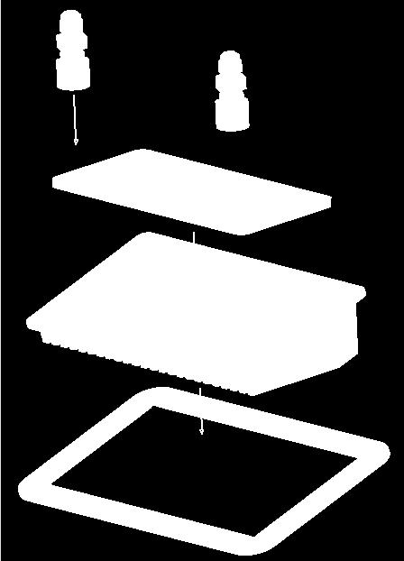
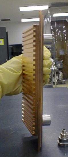
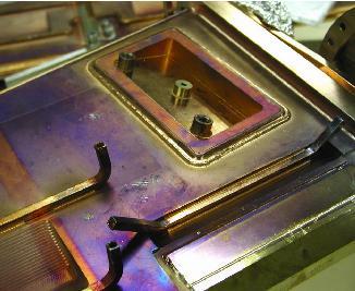
21 A Closer Look
22 Top-Up with Safety Shutters Open Stored Beam Injected Beam X-Rays Fixed Mask NORMAL X-Rays Ratchet Wall Stored Beam Injected Beam X-Rays SAFE X-Rays Injected Beam Stored Beam Injected Beam X-Rays ACCIDENT X-Rays Injected Beam 22
23 Is this a real possibility? Stored Beam Injected Beam X-Rays ACCIDENT Injected Beam Experimental X-Rays Floor Shield Wall Bad magnet fields Bad steering, energy Simulation is necessary! 23

24 SSRL Approach to Calculations Incoming Beam SPEAR3 Magnets Beamline A1 A2 Fixed Mask I Fixed Mask II Comb Mask 9.1 Ratchet Wall No assumptions about initial steering All physical positions and angles possible Energy errors! Start Point INSERTION DEVICE CM QF QD BEND SD Field simulation region Safe Endpoint Stored Beam on design orbit No magnetic field Straight trajectories Beamline Apertures Vacuum Chamber Radiation Masks Wide fringe fields A.Terebilo
25 Forward Propagation Only Fixed Mask A2 Aperture Ratchet Wall (2-ft Concrete) Injected Beam A1 Aperture Chamber boundary Stored Beam 25
26 Horizontal Angle (rad) X' [rad] Trajectories in Phase Space vacuum chamber acceptance fixed mask Phase Space at Z = Fixed Mask Phase Space at Z = Ratchet Wall Ratchet Wall Opening Fixed Mask Opening spread in angles o 10 bend (far fringe field) X [m] Horizontal Position (m) 26
27 X' [rad] X' [rad] X' [rad] X' [rad] Evolution of allowed phase space A1 A2 Fixed Mask I Ratchet Wall BPM 7 BPM 1 Insertion Device QF QD BEND SD HCOR X-Rays to Beamline Stored Beam on design orbit Initial: A1 and BPM7 After BPM BPM1 After QF A2 Dipole Entrance X [m] Dipole Entrance Dipole Exit SD Exit X [m] Allowed Phase Space in BL coordinates Z = SD exit Z = Fixed Mask Z = Ratchet Wall X [m] X [m] 27
28 X' [rad] The Metric: Separation in Phase Space to Apertures Phase Space at Z = Fixed Mask Phase Space at Z = Ratchet Wall Fixed Mask Opening Ratchet Wall Opening X [m] 28
29 Offset [m] BL apertures and Extreme Ray position [m] The Extreme Ray A1 BPM 7 ID BPM 1 A2 QF QD BEND SD beam pipe w/apertures 0 Beamline apertures and the most severely mis-steered beam Beamline Axis Extreme Ray Stored Beam on design orbit Extreme Ray Separation at Fixed Mask rise/run ~ -0.1 rad BL4 BL5 BL6 BL7 BL9 BL10 BL11 mis-steered beam ratchet wall -1.2 All other Trajectories Z [m] Position along beam line [m] 29
30 Condition for Abnormal Scenario special SLAC interpretation Large SPEAR3 magnet field error - and/or - Large injected beam energy error - AND - extensive intentional steering 30
31 BL aperture and Extreme Ray position [m] Parameter Sensitivity BL5 BL6 BL7 BL9 BL10 BL11 Nominal B/B = -10% B/B = -50% B/B = -60% Z[m] from ID center Parameter To Pass Beyond Fixed Mask To Pass Beyond Ratchet Wall E INJ /E SPEAR +59% +100% +10% B/B -48% -60% -1% (-10%) QF -100% Only with polarity reversed -25% Target Value for Interlock Limit QD +300% 55% (PS Limit) HCOR 22 mrad 30 mrad 3mrad (2 x PS Limit)

32 Alignment of Apertures is Critical Ratchet Wall A1 A2 X-Rays to Beamline A3 Insertion Device QF QD BEND SD HCOR PM Stored Beam on design orbit SPEAR Apertures Beamline-Specific Aperture +60 / -43 mm +50 / -43 mm BL9: +112 / -101 mm

33 Mechanical Drawings & Tolerances Experimental Floor x x x Ring Aperture ID source Fixed Mask Documentation Periodic checks More documentation 33

34 Dose Calculations & Testing mis-steer and measure Bauer & Liu
35 Hazard Mitigation Passive Systems -Limiting apertures in transport line (BTS) -Limiting apertures in SPEAR3 and beam lines - Permanent magnets for dipole beam lines Active Systems (Redundant Interlocks) - Injection energy interlock - BTS dipole supply - SPEAR3 magnet supplies - Stored beam interlock - Radiation detectors at each beam line 35

36 Interlock Hierarchy Hardware Interlock Envelope (reportable incident) Software Alarm Envelope A path 1 B Software Monitor Envelope * * path 2

37 A Rastafarian Logic Table Corbett & Schmerge
38 SPEAR3 Operating Sequence 1. Load operational lattice - software check of PS readbacks 2. Inject to <20 ma (orbit interlock) 3. Start orbit feedback (few microns) 4. Inject to 50 ma top-off permit 5. Open beam line injection stoppers 6. Fill 500 ma maximum (FOFB runs continuous) 7. Fill-on-fill or trickle charge
39
SPEAR 3: Operations Update and Impact of Top-Off Injection
 SPEAR 3: Operations Update and Impact of Top-Off Injection R. Hettel for the SSRL ASD 2005 SSRL Users Meeting October 18, 2005 SPEAR 3 Operations Update and Development Plans Highlights of 2005 SPEAR 3
PEP II Design Outline
 PEP II Design Outline Balša Terzić Jefferson Lab Collider Review Retreat, February 24, 2010 Outline General Information Parameter list (and evolution), initial design, upgrades Collider Ring Layout, insertions,
The Elettra Storage Ring and Top-Up Operation
 The Elettra Storage Ring and Top-Up Operation Emanuel Karantzoulis Past and Present Configurations 1994-2007 From 2008 5000 hours /year to the users 2010: Operations transition year Decay mode, 2 GeV (340mA)
Radiation Safety System for Stanford Synchrotron Radiation Laboratory*
 SLAC PUB-8817 April 16, 2001 Radiation Safety System for Stanford Synchrotron Radiation Laboratory* James C. Liu, N. E. Ipe and R. Yotam Stanford Linear Accelerator Center, P. O. Box 4349, Stanford, CA
LCLS RF Reference and Control R. Akre Last Update Sector 0 RF and Timing Systems
 LCLS RF Reference and Control R. Akre Last Update 5-19-04 Sector 0 RF and Timing Systems The reference system for the RF and timing starts at the 476MHz Master Oscillator, figure 1. Figure 1. Front end
Advanced Photon Source - Upgrades and Improvements
 Advanced Photon Source - Upgrades and Improvements Horst W. Friedsam, Jaromir M. Penicka Argonne National Laboratory, Argonne, Illinois, USA 1. INTRODUCTION The APS has been operational since 1995. Recently
Requirements for the Beam Abort Magnet and Dump
 Requirements for the Beam Abort Magnet and Dump A beam abort kicker (pulsed dipole magnet) and dump are required upbeam of the LCLS undulator in order to protect the undulator from mis-steered and poor
Status of SOLARIS Arkadiusz Kisiel
 Status of SOLARIS Arkadiusz Kisiel Solaris National Synchrotron Light Source Jagiellonian University Czerwone Maki 98 30-392 Kraków www.synchrotron.uj.edu.pl Arkadiusz.Kisiel@uj.edu.pl On behalf of SOLARIS
Experience with the Cornell ERL Injector SRF Cryomodule during High Beam Current Operation
 Experience with the Cornell ERL Injector SRF Cryomodule during High Beam Current Operation Matthias Liepe Assistant Professor of Physics Cornell University Experience with the Cornell ERL Injector SRF
Status of Elettra, top-up and other upgrades
 Status of Elettra, top-up and other upgrades Emanuel Karantzoulis ELETTRA / Trieste, Italy / 2010 November 25-26 Past and Present Configurations 1994-2007 From 2008 No full energy injection Full energy
An Operational Diagnostic Complement for Positrons at CEBAF/JLab
 An Operational Diagnostic Complement for Positrons at CEBAF/JLab Michael Tiefenback JLab, CASA International Workshop on Physics with Positrons at Jefferson Lab 12-15 September 2017 Operating CEBAF with
TWO BUNCHES WITH NS-SEPARATION WITH LCLS*
 TWO BUNCHES WITH NS-SEPARATION WITH LCLS* F.-J. Decker, S. Gilevich, Z. Huang, H. Loos, A. Marinelli, C.A. Stan, J.L. Turner, Z. van Hoover, S. Vetter, SLAC, Menlo Park, CA 94025, USA Abstract The Linac
North Damping Ring RF
 North Damping Ring RF North Damping Ring RF Outline Overview High Power RF HVPS Klystron & Klystron EPICS controls Cavities & Cavity Feedback SCP diagnostics & displays FACET-specific LLRF LLRF distribution
Production of quasi-monochromatic MeV photon in a synchrotron radiation facility
 Production of quasi-monochromatic MeV photon in a synchrotron radiation facility Presentation at University of Saskatchewan April 22-23, 2010 Yoshitaka Kawashima Brookhaven National Laboratory NSLS-II,
P. Emma, et al. LCLS Operations Lectures
 P. Emma, et al. LCLS Operations Lectures LCLS 1 LCLS Accelerator Schematic 6 MeV 135 MeV 250 MeV σ z 0.83 mm σ z 0.83 mm σ z 0.19 mm σ δ 0.05 % σ δ 0.10 % σ δ 1.6 % Linac-0 L =6 m rf gun L0-a,b Linac-1
Report on the LCLS Injector Technical Review
 Report on the LCLS Injector Technical Review Stanford Linear Accelerator Center November 3&4, 2003 Committee Members Prof. Patrick G. O Shea, Chair, University of Maryland Dr. Eric Colby, Stanford Linear
Design Studies For The LCLS 120 Hz RF Gun Injector
 BNL-67922 Informal Report LCLS-TN-01-3 Design Studies For The LCLS 120 Hz RF Gun Injector X.J. Wang, M. Babzien, I. Ben-Zvi, X.Y. Chang, S. Pjerov, and M. Woodle National Synchrotron Light Source Brookhaven
30 GHz Power Production / Beam Line
 30 GHz Power Production / Beam Line Motivation & Requirements Layout Power mode operation vs. nominal parameters Beam optics Achieved performance Problems Beam phase switch for 30 GHz pulse compression
Present Status and Future Upgrade of KEKB Injector Linac
 Present Status and Future Upgrade of KEKB Injector Linac Kazuro Furukawa, for e /e + Linac Group Present Status Upgrade in the Near Future R&D towards SuperKEKB 1 Machine Features Present Status and Future
PEP-II STATUS REPORT *
 PEP-II STATUS REPORT * Jonathan Dorfan Stanford Linear Accelerator Center, Stanford University, Stanford, CA 94309 USA For the SLAC, LBNL, LLNL PEP-II group Abstract The main design features of the PEP-II
PEP II STATUS AND PLANS *
 PEP II STATUS AND PLANS * John T. Seeman + Stanford Linear Accelerator Center, Stanford University, Stanford, CA 94309 USA The PEP II B-Factory 1 project is an e + e - colliding beam storage ring complex
3 cerl. 3-1 cerl Overview. 3-2 High-brightness DC Photocathode Gun and Gun Test Beamline
 3 cerl 3-1 cerl Overview As described before, the aim of the cerl in the R&D program includes the development of critical components for the ERL, as well as the construction of a test accelerator. The
LCLS Injector Technical Review
 LCLS Injector Technical Review Stanford Linear Accelerator Center November 3&4 2003 Review Committee Members: Prof. Patrick O Shea Chair University of Maryland Dr. E. Colby Stanford Linear Accelerator
A Facility for Accelerator Physics and Test Beam Experiments
 A Facility for Accelerator Physics and Test Beam Experiments U.S. Department of Energy Review Roger Erickson for the FACET Design Team February 20, 2008 SLAC Overview with FACET FACET consists of four
Status of RF Power and Acceleration of the MAX IV - LINAC
 Status of RF Power and Acceleration of the MAX IV - LINAC Dionis Kumbaro ESLS RF Workshop 2015 MAX IV Laboratory A National Laboratory for synchrotron radiation at Lunds University 1981 MAX-lab is formed
Summary of the 1 st Beam Line Review Meeting Injector ( )
") Summary of the 1 st Beam Line Review Meeting Injector (23.10.2006) 15.11.2006 Review the status of: beam dynamics understanding and simulations completeness of beam line description conceptual design of
Summary of the 1 st Beam Line Review Meeting Injector (23.10.2006) 15.11.2006 Review the status of: beam dynamics understanding and simulations completeness of beam line description conceptual design of
New Filling Pattern for SLS-FEMTO
 SLS-TME-TA-2009-0317 July 14, 2009 New Filling Pattern for SLS-FEMTO Natalia Prado de Abreu, Paul Beaud, Gerhard Ingold and Andreas Streun Paul Scherrer Institut, CH-5232 Villigen PSI, Switzerland A new
COMMISSIONING SCENARIOS FOR THE J-PARC ACCELERATOR COMPLEX
 COMMISSIONING SCENARIOS FOR THE J-PARC ACCELERATOR COMPLEX T. Koseki, M. Ikegami, M. Tomizawa, Accelerator Laboratory, KEK, Tsukuba, Japan F. Noda, JAEA, Tokai, Japan Abstract The J-PARC (Japan Proton
Operational Status of PF-Ring and PF-AR after the Earthquake
 Journal of Physics: Conference Series Operational Status of PF-Ring and PF-AR after the Earthquake To cite this article: T Honda et al 2013 J. Phys.: Conf. Ser. 425 042014 Related content - Design and
OPERATIONAL EXPERIENCE AT J-PARC
 OPERATIONAL EXPERIENCE AT J-PARC Hideaki Hotchi, ) for J-PARC commissioning team ), 2), ) Japan Atomic Energy Agency (JAEA), Tokai, Naka, Ibaraki, 39-95 Japan, 2) High Energy Accelerator Research Organization
4.4 Injector Linear Accelerator
 4.4 Injector Linear Accelerator 100 MeV S-band linear accelerator based on the components already built for the S-Band Linear Collider Test Facility at DESY [1, 2] will be used as an injector for the CANDLE
Characterizing Transverse Beam Dynamics at the APS Storage Ring Using a Dual-Sweep Streak Camera
 Characterizing Transverse Beam Dynamics at the APS Storage Ring Using a Dual-Sweep Streak Camera Bingxin Yang, Alex H. Lumpkin, Katherine Harkay, Louis Emery, Michael Borland, and Frank Lenkszus Advanced
FINAL DESIGN OF ILC RTML EXTRACTION LINE FOR SINGLE STAGE BUNCH COMPRESSOR
 BNL-94942-2011-CP FINAL DESIGN OF ILC RTML EXTRACTION LINE FOR SINGLE STAGE BUNCH COMPRESSOR S. Sletskiy and N. Solyak Presented at the 2011 Particle Accelerator Conference (PAC 11) New York, NY March
Hall-B Beamline Commissioning Plan for CLAS12
 Hall-B Beamline Commissioning Plan for CLAS12 Version 1.5 S. Stepanyan December 19, 2017 1 Introduction The beamline for CLAS12 utilizes the existing Hall-B beamline setup with a few modifications and
Recent APS Storage Ring Instrumentation Developments. Glenn Decker Advanced Photon Source Beam Diagnostics March 1, 2010
 Recent APS Storage Ring Instrumentation Developments Glenn Decker Advanced Photon Source Beam Diagnostics March 1, 2010 Ring Diagnostics Overview RF beam position monitor technology Photon beam position
FIRST SIMULTANEOUS TOP-UP OPERATION OF THREE DIFFERENT RINGS IN KEK INJECTOR LINAC
 FIRST SIMULTANEOUS TOP-UP OPERATION OF THREE DIFFERENT RINGS IN KEK INJECTOR LINAC M. Satoh #, for the IUC * Accelerator Laboratory, High Energy Accelerator Research Organization (KEK) 1-1 Oho, Tsukuba,
2008 JINST 3 S LHC Machine THE CERN LARGE HADRON COLLIDER: ACCELERATOR AND EXPERIMENTS. Lyndon Evans 1 and Philip Bryant (editors) 2
 2") PUBLISHED BY INSTITUTE OF PHYSICS PUBLISHING AND SISSA RECEIVED: January 14, 2007 REVISED: June 3, 2008 ACCEPTED: June 23, 2008 PUBLISHED: August 14, 2008 THE CERN LARGE HADRON COLLIDER: ACCELERATOR AND
PUBLISHED BY INSTITUTE OF PHYSICS PUBLISHING AND SISSA RECEIVED: January 14, 2007 REVISED: June 3, 2008 ACCEPTED: June 23, 2008 PUBLISHED: August 14, 2008 THE CERN LARGE HADRON COLLIDER: ACCELERATOR AND
The PEFP 20-MeV Proton Linear Accelerator
 Journal of the Korean Physical Society, Vol. 52, No. 3, March 2008, pp. 721726 Review Articles The PEFP 20-MeV Proton Linear Accelerator Y. S. Cho, H. J. Kwon, J. H. Jang, H. S. Kim, K. T. Seol, D. I.
Upgrading LHC Luminosity
 1 Upgrading LHC Luminosity 2 Luminosity (cm -2 s -1 ) Present (2011) ~2 x10 33 Beam intensity @ injection (*) Nominal (2015?) 1 x 10 34 1.1 x10 11 Upgraded (2021?) ~5 x10 34 ~2.4 x10 11 (*) protons per
Diamond RF Status (RF Activities at Daresbury) Mike Dykes
 Mike Dykes") Diamond RF Status (RF Activities at Daresbury) Mike Dykes ASTeC What is it? What does it do? Diamond Status Linac Booster RF Storage Ring RF Summary Content ASTeC ASTeC was formed in 2001 as a centre of
Diamond RF Status (RF Activities at Daresbury) Mike Dykes ASTeC What is it? What does it do? Diamond Status Linac Booster RF Storage Ring RF Summary Content ASTeC ASTeC was formed in 2001 as a centre of
Tutorial: Trak design of an electron injector for a coupled-cavity linear accelerator
 Tutorial: Trak design of an electron injector for a coupled-cavity linear accelerator Stanley Humphries, Copyright 2012 Field Precision PO Box 13595, Albuquerque, NM 87192 U.S.A. Telephone: +1-505-220-3975
PEP II Status and Plans
 SLAC-PUB-6854 September 1998 PEP II Status and Plans By John T. Seeman Invited talk presented at the 16th IEEE Particle Accelerator Conference (PAC 95) and International Conference on High Energy Accelerators,
An Overview of Beam Diagnostic and Control Systems for AREAL Linac
 An Overview of Beam Diagnostic and Control Systems for AREAL Linac Presenter G. Amatuni Ultrafast Beams and Applications 04-07 July 2017, CANDLE, Armenia Contents: 1. Current status of existing diagnostic
Spear3 RF System Sam Park 11/06/2003. Spear3 RF System. High Power Components Operation and Control. RF Requirement.
 Spear3 RF System RF Requirement Overall System High Power Components Operation and Control SPEAR 3 History 1996 Low emittance lattices explored 1996 SPEAR 3 proposed 11/97 SPEAR 3 design study team formed
IOT OPERATIONAL EXPERIENCE ON ALICE AND EMMA AT DARESBURY LABORATORY
 IOT OPERATIONAL EXPERIENCE ON ALICE AND EMMA AT DARESBURY LABORATORY A. Wheelhouse ASTeC, STFC Daresbury Laboratory ESLS XVIII Workshop, ELLETRA 25 th 26 th November 2010 Contents Brief Description ALICE
The basic parameters of the pre-injector are listed in the Table below. 100 MeV
 3.3 The Pre-injector The high design brightness of the SLS requires very high phase space density of the stored electrons, leading to a comparatively short lifetime of the beam in the storage ring. This,
Program Risks Risk Analysis Fallback Plans for the. John T. Seeman DOE PEP-II Operations Review April 26, 2006
 Program Risks Risk Analysis Fallback Plans for the PEP-II B-FactoryB John T. Seeman DOE PEP-II Operations Review April 26, 2006 OPS Review Topics Are there any PEP-II program risks? Has the laboratory
HIGH POWER BEAM DUMP AND TARGET / ACCELERATOR INTERFACE PROCEDURES *
 HIGH POWER BEAM DUMP AND TARGET / ACCELERATOR INTERFACE PROCEDURES * J. Galambos, W. Blokland, D. Brown, C. Peters, M. Plum, Spallation Neutron Source, ORNL, Oak Ridge, TN 37831, U.S.A. Abstract Satisfying
Digital BPMs and Orbit Feedback Systems
 Digital BPMs and Orbit Feedback Systems, M. Böge, M. Dehler, B. Keil, P. Pollet, V. Schlott Outline stability requirements at SLS storage ring digital beam position monitors (DBPM) SLS global fast orbit
RF Design of the LCLS Gun C.Limborg, Z.Li, L.Xiao, J.F. Schmerge, D.Dowell, S.Gierman, E.Bong, S.Gilevich February 9, 2005
 RF Design of the LCLS Gun C.Limborg, Z.Li, L.Xiao, J.F. Schmerge, D.Dowell, S.Gierman, E.Bong, S.Gilevich February 9, 2005 Summary Final dimensions for the LCLS RF gun are described. This gun, referred
Tolerances on Magnetic Misalignments in SESAME Storage Ring
 Tolerances on Magnetic Misalignments in SESAME Storage Ring SES-TE-AP-TN-0003 April 20, 2014 Authored by: Reviewed by: Approved by: Access List : Maher Attal Erhard Huttle Erhard Huttle ---Internal ---------
Linac 4 Instrumentation K.Hanke CERN
 Linac 4 Instrumentation K.Hanke CERN CERN Linac 4 PS2 (2016?) SPL (2015?) Linac4 (2012) Linac4 will first inject into the PSB and then can be the first element of a new LHC injector chain. It will increase
Accelerator Systems of the TPS
 Ambient Ground Motion and Civil Engineering for Low Emittance Electron Storage Ring July 2-22, 2005, Hsinchu, Taiwan Accelerator Systems of the TPS Preinjector, Booster Synchrotron, Transfer Line, and
CLEX (CLIC Experimental Area)
") CLEX (CLIC Experimental Area) Status and plans G.Geschonke for Hans Braun CERN CT3 coll meetg 2005 CLEX 1 CT3 objectives R1.1 CLIC accelerating structure, R1.2 rive beam scheme with a fully loaded linac
CLEX (CLIC Experimental Area) Status and plans G.Geschonke for Hans Braun CERN CT3 coll meetg 2005 CLEX 1 CT3 objectives R1.1 CLIC accelerating structure, R1.2 rive beam scheme with a fully loaded linac
LHC Beam Instrumentation Further Discussion
 LHC Beam Instrumentation Further Discussion LHC Machine Advisory Committee 9 th December 2005 Rhodri Jones (CERN AB/BDI) Possible Discussion Topics Open Questions Tune measurement base band tune & 50Hz
ALBA. Libera Workshop 16 A. Olmos
 LIBERAs @ ALBA Libera Workshop 16 A. Olmos Content Fast Orbit Feedback At a glance Equipments Implementation Limitations In operation Bunch-by- Bunch system At a glance Ported Software Status What else
PRESENT STATUS OF J-PARC
 PRESENT STATUS OF J-PARC # F. Naito, KEK, Tsukuba, Japan Abstract Japan Proton Accelerator Research Complex (J-PARC) is the scientific facility with the high-intensity proton accelerator aiming to realize
A Cathode Development Cornell Cultera This scope includes all labor and purchases required produce photocathodes required by CBETA.
 A1.01 PROJECT MANAGEMENT BNL/Cornell Michnoff A1.01.01 Milestones BNL/Cornell Michnoff This scope is a placeholder for all project high level milestones for NYSERDA. There is no cost or labor related to
EPJ Web of Conferences 95,
 EPJ Web of Conferences 95, 04012 (2015) DOI: 10.1051/ epjconf/ 20159504012 C Owned by the authors, published by EDP Sciences, 2015 The ELENA (Extra Low Energy Antiproton) project is a small size (30.4
COMMISSIONING OF THE ALBA FAST ORBIT FEEDBACK SYSTEM
 COMMISSIONING OF THE ALBA FAST ORBIT FEEDBACK SYSTEM A. Olmos, J. Moldes, R. Petrocelli, Z. Martí, D. Yepez, S. Blanch, X. Serra, G. Cuni, S. Rubio, ALBA-CELLS, Barcelona, Spain Abstract The ALBA Fast
Detailed Design Report
 Detailed Design Report Chapter 4 MAX IV Injector 4.6. Acceleration MAX IV Facility CHAPTER 4.6. ACCELERATION 1(10) 4.6. Acceleration 4.6. Acceleration...2 4.6.1. RF Units... 2 4.6.2. Accelerator Units...
Equipment Installation, Planning, Layout, organisation and updates
 Equipment Installation, Planning, Layout, organisation and updates Simon Mataguez, Julie Coupard with contributions of the LIU-PLI team Table of contents: LIU installation activities Organisation of the
Photo cathode RF gun -
 Photo cathode RF gun - *),,, ( 05 Nov. 2004 Spring8 UTNL Linac & Mg Photocathode RF Gun Mg photocathode NERL, 18 MeV Linac and the RF gun Electron Beam Mg photocathode Mg photocathode RF gun of SPring8
First Simultaneous Top-up Operation of Three Different Rings in KEK Injector Linac
 First Simultaneous Top-up Operation of Three Different Rings in KEK Injector Linac Masanori Satoh (Acc. Lab., KEK) for the injector upgrade group 2010/9/16 1 Overview of Linac Beam Operation 2010/9/16
Sérgio Rodrigo Marques
 Sérgio Rodrigo Marques (on behalf of the beam diagnostics group) sergio@lnls.br Outline Introduction Stability Requirements General System Requirements FOFB Strategy Hardware Overview Performance Tests:
Future Performance of the LCLS
 Future Performance of the LCLS J. Welch for many* SLAC National Accelerator Laboratory FLS 2010, ICFA Beam Dynamics Workshop on Future Light Sources, March 1-5, 2010. SLAC National Accelerator Laboratory,
STATUS OF THE SWISSFEL C-BAND LINEAR ACCELERATOR
 Proceedings of FEL213, New York, NY, USA STATUS OF THE SWISSFEL C-BAND LINEAR ACCELERATOR F. Loehl, J. Alex, H. Blumer, M. Bopp, H. Braun, A. Citterio, U. Ellenberger, H. Fitze, H. Joehri, T. Kleeb, L.
High Brightness Injector Development and ERL Planning at Cornell. Charlie Sinclair Cornell University Laboratory for Elementary-Particle Physics
 High Brightness Injector Development and ERL Planning at Cornell Charlie Sinclair Cornell University Laboratory for Elementary-Particle Physics June 22, 2006 JLab CASA Seminar 2 Background During 2000-2001,
EUROFEL-Report-2007-DS EUROPEAN FEL Design Study
 EUROFEL-Report-2007-DS4-095 EUROPEAN FEL Design Study Deliverable N : D 4.3 Deliverable Title: Task: Authors: Generation of 3rd harmonic photons at 90 nm DS-4 see next page Contract N : 011935 Project
Beam instrumentation at the 1-MW proton J-PARC RCS
 Beam instrumentation at the 1-MW proton J-PARC RCS HB2014 54th ICFA Advanced Beam Dynamics Workshop on High-Intensity, High-Brightness and High Power Hadron Beams East Lansing, MI Nov.12, 2014 Kazami Yamamoto
Periodic Seasonal Variation of Magnets Level of the STB ring
 Periodic Seasonal Variation of Magnets Level of the STB ring Shigenobu Takahashi Laboratory of Nuclear Science,Tohoku University, Mikamine 1-2-1, Taihaku-ku, Sendai 982-0826, Japan 1. Introduction The
COMMISSIONING RESULTS OF BEAM DIAGNOSTICS FOR THE PETRA III LIGHT SOURCE
 Proceedings of DIPAC9, Basel, Switzerland MOOB2 COMMISSIONING RESULTS OF BEAM DIAGNOSTICS FOR THE PETRA III LIGHT SOURCE K. Balewski #, G. Kube, K. Wittenburg, A. Brenger, H.-T. Duhme, V. Gharibyan, J.
Scavenger Extraction. Karen Goldsmith Shawn Alverson
 Scavenger Extraction Karen Goldsmith Shawn Alverson Topics Beam line and area maps High Power Target (HPT) How to establish first beam to HPT Setting energy (configs, multiknobs, Fast Phase Shifters, etc.)
Current status of XFEL/SPring-8 project and SCSS test accelerator
 Current status of XFEL/SPring-8 project and SCSS test accelerator Takahiro Inagaki for XFEL project in SPring-8 inagaki@spring8.or.jp Outline (1) Introduction (2) Key technology for compactness (3) Key
TOP-UP OPERATION IN LIGHT SOURCES
 TOP-UP OPERATION IN LIGHT SOURCES H. Ohkuma * JASRI/SPring-8, Hyogo 679-5198, Japan Abstract The top-up operation for user experiments has been performed at several light sources, and at most of the new
Electron Bypass Line (EBL) Design Electrons to A-line bypassing LCLS T. Fieguth, R. Arnold
 Design Electrons to A-line bypassing LCLS T. Fieguth, R. Arnold") September 2007 SLAC-TN-08-001 Electron Bypass Line (EBL) Design Electrons to A-line bypassing LCLS T. Fieguth, R. Arnold Introduction Forty one years ago, September 20, 1966, the first beam entered End
September 2007 SLAC-TN-08-001 Electron Bypass Line (EBL) Design Electrons to A-line bypassing LCLS T. Fieguth, R. Arnold Introduction Forty one years ago, September 20, 1966, the first beam entered End
RADIATION SAFETY SYSTEM OF THE B-FACTORY AT THE STANFORD LINEAR ACCELERATOR CENTER
 SLAC-PUB-7786 (August 1998) RADIATION SAFETY SYSTEM OF THE B-FACTORY AT THE STANFORD LINEAR ACCELERATOR CENTER J. C. Liu, X. S. Mao, W. R. Nelson, J. Seeman, D. Schultz, G. Nelson, P. Bong, B. Gray Stanford
Accelerator Instrumentation RD. Monday, July 14, 2003 Marc Ross
 Monday, Marc Ross Linear Collider RD Most RD funds address the most serious cost driver energy The most serious impact of the late technology choice is the failure to adequately address luminosity RD issues
LHC Nominal injection sequence
 LHC Nominal injection sequence Mike Lamont Acknowledgements: Reyes Alemany Fernandez, Brennan Goddard Nominal injection Overall injection scheme Pilot R1, Pilot R2, Intermediate R1 Optimise Intermediate
CONSTRUCTION AND COMMISSIONING OF BEPCII
 Abstract CONSTRUCTION AND COMMISSIONING OF BEPCII C. Zhang, J.Q. Wang, L. Ma and G.X.Pei for the BEPCII Team, IHEP, CAS P.O.Box 918, Beijing 100049, China BEPCII is the major upgrade of BEPC (Beijing Electron-
CERN S PROTON SYNCHROTRON COMPLEX OPERATION TEAMS AND DIAGNOSTICS APPLICATIONS
 Marc Delrieux, CERN, BE/OP/PS CERN S PROTON SYNCHROTRON COMPLEX OPERATION TEAMS AND DIAGNOSTICS APPLICATIONS CERN s Proton Synchrotron (PS) complex How are we involved? Review of some diagnostics applications
Status of CTF3. G.Geschonke CERN, AB
 Status of CTF3 G.Geschonke CERN, AB CTF3 layout CTF3 - Test of Drive Beam Generation, Acceleration & RF Multiplication by a factor 10 Drive Beam Injector ~ 50 m 3.5 A - 2100 b of 2.33 nc 150 MeV - 1.4
Screen investigations for low energetic electron beams at PITZ
 1 Screen investigations for low energetic electron beams at PITZ S. Rimjaem, J. Bähr, H.J. Grabosch, M. Groß Contents Review of PITZ setup Screens and beam profile monitors at PITZ Test results Summary
SUMMARY OF THE ILC R&D AND DESIGN
 SUMMARY OF THE ILC R&D AND DESIGN B. C. Barish, California Institute of Technology, USA Abstract The International Linear Collider (ILC) is a linear electron-positron collider based on 1.3 GHz superconducting
INFN School on Electron Accelerators. RF Power Sources and Distribution
 INFN School on Electron Accelerators 12-14 September 2007, INFN Sezione di Pisa Lecture 7b RF Power Sources and Distribution Carlo Pagani University of Milano INFN Milano-LASA & GDE The ILC Double Tunnel
TITLE PAGE. Title of paper: PUSH-PULL FEL, A NEW ERL CONCEPT Author: Andrew Hutton. Author Affiliation: Jefferson Lab. Requested Proceedings:
 TITLE PAGE Title of paper: PUSH-PULL FEL, A NEW ERL CONCEPT Author: Andrew Hutton Author Affiliation: Jefferson Lab Requested Proceedings: Unique Session ID: Classification Codes: Keywords: Energy Recovery,
Activities on FEL Development and Application at Kyoto University
 Activities on FEL Development and Application at Kyoto University China-Korea-Japan Joint Workshop on Electron / Photon Sources and Applications Dec. 2-3, 2010 @ SINAP, Shanghai Kai Masuda Inst. Advanced
Safety Considerations For The Top-up Operation Of An 8 GeV Class Synchrotron Radiation Facility
 Safety Considerations For The Top-up Operation Of An 8 GeV Class Synchrotron Radiation Facility Yoshihiro Asano 1, and Tetsuya Takagi 2 1 Synchrotron Radiation Research Center. Japan Atomic Energy Research
Development of beam-collision feedback systems for future lepton colliders. John Adams Institute for Accelerator Science, Oxford University
 Development of beam-collision feedback systems for future lepton colliders P.N. Burrows 1 John Adams Institute for Accelerator Science, Oxford University Denys Wilkinson Building, Keble Rd, Oxford, OX1
Status and Plans for PEP-II
 Status and Plans for PEP-II John Seeman SLAC Particle and Particle-Astrophysics DOE HEPAP P5 Review April 21, 2006 Topics Luminosity records for PEP-II in October 2005 Fall shut-down upgrades Run 5b turn
ANKA Status Report. N.Smale, A.-S. Müller, E. Huttel, M.Schuh Slides courtesy of A.-S. Müller and C.Heske.
 ANKA Status Report N.Smale, A.-S. Müller, E. Huttel, M.Schuh Slides courtesy of A.-S. Müller and C.Heske. KIT - University of the State of Baden-Wuerttemberg and National Laboratory of the Helmholtz Association
Development of an Abort Gap Monitor for High-Energy Proton Rings *
 Development of an Abort Gap Monitor for High-Energy Proton Rings * J.-F. Beche, J. Byrd, S. De Santis, P. Denes, M. Placidi, W. Turner, M. Zolotorev Lawrence Berkeley National Laboratory, Berkeley, USA
CLIC Feasibility Demonstration at CTF3
 CLIC Feasibility Demonstration at CTF3 Roger Ruber Uppsala University, Sweden, for the CLIC/CTF3 Collaboration http://cern.ch/clic-study LINAC 10 MO303 13 Sep 2010 The Key to CLIC Efficiency NC Linac for
SLAC R&D Program for a Polarized RF Gun
 ILC @ SLAC R&D Program for a Polarized RF Gun SLAC-PUB-11657 January 2006 (A) J. E. CLENDENIN, A. BRACHMANN, D. H. DOWELL, E. L. GARWIN, K. IOAKEIMIDI, R. E. KIRBY, T. MARUYAMA, R. A. MILLER, C. Y. PRESCOTT,
A Fifteen Year Perspective on the Design and Performance of the SNS Accelerator
 A Fifteen Year Perspective on the Design and Performance of the SNS Accelerator S. Cousineau (On behalf of the SNS project) HB2016, Sweden July 04, 2016 ORNL is managed by UT-Battelle for the US Department
LEPTON COLLIDER OPERATION WITH CONSTANT CURRENTS Λ
 SLAC-PUB-11706 LEPTON COLLIDER OPERATION WITH CONSTANT CURRENTS Λ U. Wienands y, SLAC, Stanford, CA, USA Abstract Electron-positron colliders have been operating in a topup-and-coast fashion with a cycle
Availability and Reliability Issues for the ILC
 Availability and Reliability Issues for the ILC SLAC Presented at PAC07 26 June 07 Contents Introduction and purpose of studies The availability simulation What was modeled (important assumptions) Some
Beam Losses During LCLS Injector Phase-1 1 Operation
 Beam Losses During LCLS Injector Phase-1 1 Operation & Paul Emma September 28, 2006 Radiation Safety Committee Review Scope of Phase 1 Operation Request for Three Operating Modes Operating Plan for Phase
Proton Engineering Frontier Project
 Proton Engineering Frontier Project OECD Nuclear Energy Agency Fifth International Workshop on the Utilisation and Reliability of High Power Proton Accelerators (HPPA5) (6-9 May 2007, Mol, Belgium) Yong-Sub
Bunch-by-bunch feedback and LLRF at ELSA
 Bunch-by-bunch feedback and LLRF at ELSA Dmitry Teytelman Dimtel, Inc., San Jose, CA, USA February 9, 2010 Outline 1 Feedback Feedback basics Coupled-bunch instabilities and feedback Beam and feedback