R&S RTO Digital Oscilloscope Specifications
|
|
|
- Emmeline Lambert
- 6 years ago
- Views:
Transcription


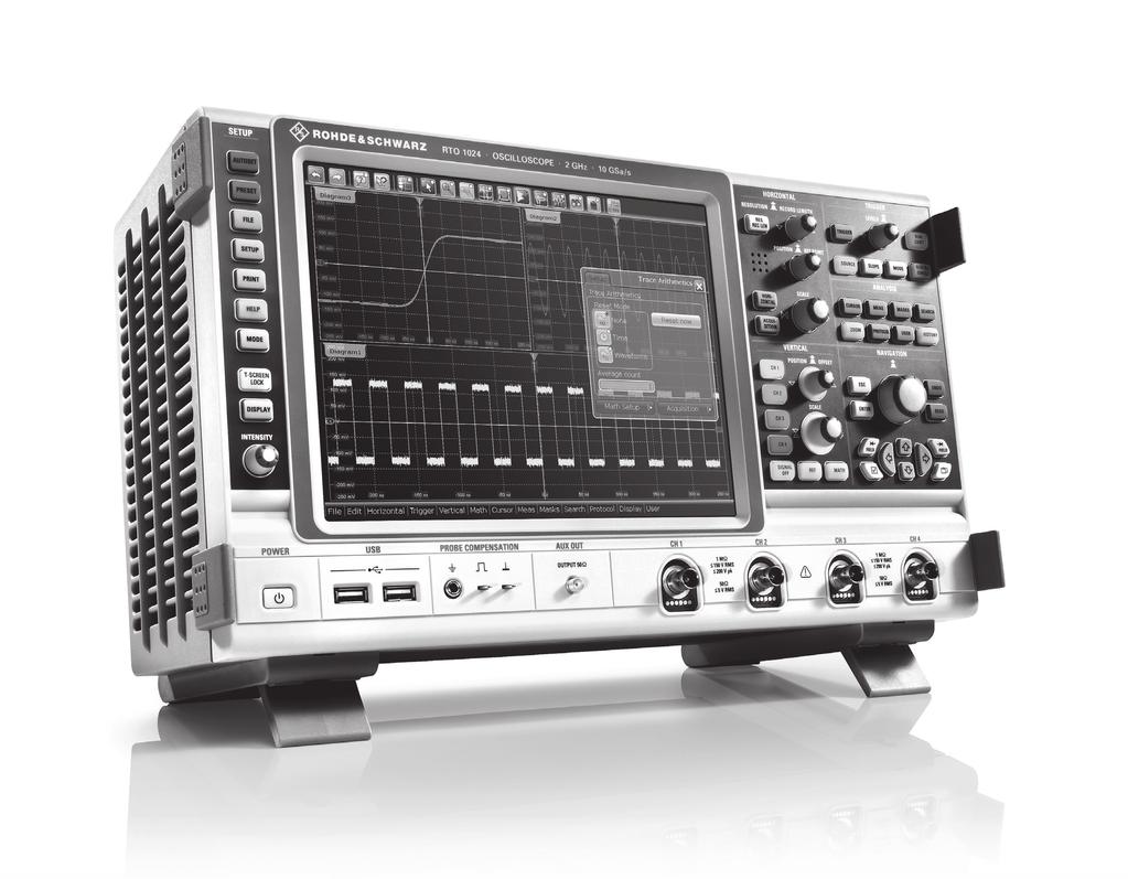
1 R&S RTO Digital Oscilloscope Specifications Test & Measurement Data Sheet 08.00
2 CONTENTS Definitions... 3 Base unit... 4 Vertical system... 4 Horizontal system... 5 Acquisition system... 6 Trigger system... 7 Waveform measurements... 9 Mask testing Waveform math Search and mark function Display characteristics Input and output General data Options R&S RTO-B Vertical system Horizontal system Acquisition system Trigger system Waveform measurements Waveform math Search and mark functions Display characteristics R&S RTO-B R&S RTO-B R&S RTO-B R&S RTO-K R&S RTO-K R&S RTO-K R&S RTO-K R&S RTO-K R&S RTO-K R&S RTO-K Ordering information Rohde & Schwarz R&S RTO Digital Oscilloscope

3 Definitions General Product data applies under the following conditions: Three hours storage at ambient temperature followed by 30 minutes warm-up operation Specified environmental conditions met Recommended calibration interval adhered to All internal automatic adjustments performed, if applicable Specifications with limits Represent warranted product performance by means of a range of values for the specified parameter. These specifications are marked with limiting symbols such as <,, >,, ±, or descriptions such as maximum, limit of, minimum. Compliance is ensured by testing or is derived from the design. Test limits are narrowed by guard bands to take into account measurement uncertainties, drift and aging, if applicable. Specifications without limits Represent warranted product performance for the specified parameter. These specifications are not specially marked and represent values with no or negligible deviations from the given value (e.g. dimensions or resolution of a setting parameter). Compliance is ensured by design. Typical data (typ.) Characterizes product performance by means of representative information for the given parameter. When marked with <, > or as a range, it represents the performance met by approximately 80 % of the instruments at production time. Otherwise, it represents the mean value. Nominal values (nom.) Characterize product performance by means of a representative value for the given parameter (e.g. nominal impedance). In contrast to typical data, a statistical evaluation does not take place and the parameter is not tested during production. Measured values (meas.) Characterize expected product performance by means of measurement results gained from individual samples. Uncertainties Represent limits of measurement uncertainty for a given measurand. Uncertainty is defined with a coverage factor of 2 and has been calculated in line with the rules of the Guide to the Expression of Uncertainty in Measurement (GUM), taking into account environmental conditions, aging, wear and tear. Device settings and GUI parameters are indicated as follows: parameter: value. Typical data as well as nominal and measured values are not warranted by Rohde & Schwarz. Rohde & Schwarz R&S RTO Digital Oscilloscope 3
4 Base unit Vertical system Input channels R&S RTO channels R&S RTO channels R&S RTO channels R&S RTO channels R&S RTO channels R&S RTO channels R&S RTO channels Input impedance 50 Ω ± 2 % (50 Ω ± 1.5 % from +15 C to +30 C), 1 MΩ ± 1 % 15 pf (meas.) Analog bandwidth ( 3 db) at 50 Ω input impedance R&S RTO1002 and R&S RTO MHz R&S RTO1012 and R&S RTO GHz R&S RTO1022 and R&S RTO GHz R&S RTO GHz at 1 MΩ input impedance 500 MHz (meas.) Analog bandwidth limits max. 1.5 db, min. 4 db 200 MHz, 20 MHz Rise time/fall time 10 % to 90 % at 50 Ω (calculated) R&S RTO1002 and R&S RTO ps R&S RTO1012 and R&S RTO ps R&S RTO1022 and R&S RTO ps R&S RTO ps Input VSWR input frequency 2 GHz 1.25 (meas.) input frequency > 2 GHz 1.4 (meas.) Vertical resolution 8 bit Effective number of bits of digitizer for full-scale sine-wave signal with frequency equal to or lower than 3 db bandwidth > 7.0 bit (meas.) DC gain accuracy offset and position set to 0 V, after self-alignment at 50 Ω, input sensitivity > 5 mv/div ±1.5 % at 50 Ω, input sensitivity 5 mv/div ±2 % at 1 MΩ ±2 % Input coupling at 50 Ω DC and GND at 1 MΩ DC, AC and GND Input sensitivity at 50 Ω 1 mv/div to 1 V/div at 1 MΩ 1 mv/div to 10 V/div Maximum input voltage at 50 Ω 5 V (RMS) at 1 MΩ 150 V (RMS), 200 V (V p ), derates at 20 db/decade to 5 V (RMS) above 250 khz Position range ±5 div Offset range at 50 Ω input sensitivity 316 mv/div to 1 V/div ±10 V 100 mv/div to 316 mv/div ±3 V 1 mv/div to 100 mv/div ±1 V Offset range at 1 MΩ input sensitivity 3.16 V/div to 10 V/div ±(115 V input sensitivity 5 div) 1 V/div to 3.16 V/div ±100 V 316 mv/div to 1 V/div ±(11.5 V input sensitivity 5 div) 100 mv/div to 316 mv/div ±10 V 31.6 mv/div to 100 mv/div ±(1.15 V input sensitivity 5 div) 1 mv/div to 31.6 mv/div ±1 V Offset accuracy ±(0.35 % net offset mv div input sensitivity) (net offset = offset position input sensitivity) DC measurement accuracy after adequate suppression of measurement noise using high-resolution sampling mode or waveform averaging or ±(DC gain accuracy reading net offset + offset accuracy) a combination of both Channel-to-channel isolation input frequency 2 GHz > 60 db (each channel at same input sensitivity) input frequency > 2GHz > 50 db 4 Rohde & Schwarz R&S RTO Digital Oscilloscope
5 RMS noise floor at 50 Ω (typ.) input sensitivity R&S RTO1002, R&S RTO1004 R&S RTO1012, R&S RTO mv/div 0.08 mv 0.10 mv 2 mv/div 0.08 mv 0.10 mv 5 mv/div 0.11 mv 0.12 mv 10 mv/div 0.17 mv 0.20 mv 20 mv/div 0.28 mv 0.36 mv 50 mv/div 0.70 mv 0.85 mv 100 mv/div 1.30 mv 1.65 mv 200 mv/div 2.70 mv 3.30 mv 500 mv/div 7.00 mv 8.70 mv 1 V/div 13.7 mv 17.0 mv input sensitivity R&S RTO1022, R&S RTO1024 R&S RTO1044 (meas.) 1 mv/div 0.15 mv 0.24 mv 2 mv/div 0.15 mv 0.25 mv 5 mv/div 0.18 mv 0.28 mv 10 mv/div 0.28 mv 0.42 mv 20 mv/div 0.50 mv 0.72 mv 50 mv/div 1.22 mv 1.80 mv 100 mv/div 2.39 mv 3.60 mv 200 mv/div 4.80 mv 7.20 mv 500 mv/div 12.0 mv 18.0 mv 1 V/div 23.9 mv 36.0 mv Horizontal system Timebase range selectable between 25 ps/div and 50 s/div, time per div settable to any value within range Channel deskew ±100 ns Reference position 10 % to 90 % of measurement display area Trigger offset range max. +(memory depth/current sampling rate) min s Modes normal, roll Channel-to-channel skew < 100 ps (meas.) Timebase accuracy standard after delivery/calibration, at +23 C ±5 ppm during calibration interval ±10 ppm with R&S RTO-B4 option after delivery/calibration, at +23 C ±0.02 ppm during calibration interval ±0.2 ppm long-term stability (more than one year since calibration) ±( years since calibration) ppm Delta time accuracy corresponds to time error between two edges on same acquisition and channel; signal amplitude greater than 5 divisions, measurement threshold set to 50 %, vertical gain 10 mv/div or greater; rise time lower than four sample periods; waveform acquired in realtime mode ±(K/realtime sampling rate + timebase accuracy reading ) (peak) (meas.) where K = 0.15 (R&S RTO1002, R&S RTO1004) K = 0.18 (R&S RTO1012, R&S RTO1014) K = 0.25 (R&S RTO1022, R&S RTO1024) K = 0.43 (R&S RTO1044) Rohde & Schwarz R&S RTO Digital Oscilloscope 5
6 Acquisition system Realtime sampling rate R&S RTO1002, R&S RTO1004, R&S RTO1012, R&S RTO1014, R&S RTO1022, R&S RTO1024 R&S RTO1044 max. 10 Gsample/s on each channel max. 10 Gsample/s on 4 channels, max. 20 Gsample/s on 2 channels Realtime waveform acquisition rate max. > waveforms/s Memory depth standard R&S RTO1002, R&S RTO1012, R&S RTO Msample on 2 channels, 40 Msample on 1 channel R&S RTO1004, R&S RTO1014, R&S RTO1024, R&S RTO Msample on 4 channels, 40 Msample on 2 channels, 80 Msample on 1 channel R&S RTO-B101 option R&S RTO1002, R&S RTO1012, R&S RTO Msample on 2 channels, 100 Msample on 1 channel R&S RTO1004, R&S RTO1014, R&S RTO1024, R&S RTO Msample on 4 channels, 100 Msample on 2 channels, 200 Msample on 1 channel R&S RTO-B102 option R&S RTO1002, R&S RTO1012, R&S RTO Msample on 2 channels, 200 Msample on 1 channel R&S RTO1004, R&S RTO1014, R&S RTO1024, R&S RTO Msample on 4 channels, 200 Msample on 2 channels, 400 Msample on 1 channel Decimation modes sample first sample in decimation interval peak detect largest and smallest sample in decimation interval high resolution average value of samples in decimation interval root mean square root of squared average of samples in decimation interval Waveform arithmetic off no arithmetic envelope envelope of acquired waveforms average average of acquired waveforms, max. average depth depends on decimation mode 1 sample max high resolution max root mean square max. 255 reset condition no reset (standard), reset by time, reset by number of processed waveforms Waveform streams per channel up to 3 with independent selection of decimation mode and waveform arithmetic Sampling modes realtime mode max. sampling rate set by digitizer interpolated time enhancement of sampling resolution by interpolation; max. equivalent sampling rate is 4 Tsample/s equivalent time enhancement of sampling resolution by repetitive acquisition; max. equivalent sampling rate is 4 Tsample/s Interpolation modes linear, sin(x)/x, sample&hold Ultra segmented mode continuous recording of waveforms in acquisition memory without interruption due to visualization; blind time between consecutive acquisitions less than 300 ns 1 Waveform averaging is not compatible with peak detect decimation. 6 Rohde & Schwarz R&S RTO Digital Oscilloscope
7 Trigger system Sources R&S RTO1002, R&S RTO1012, channel 1, channel 2 R&S RTO1022 R&S RTO1004, R&S RTO1014, channel 1, channel 2, channel 3, channel 4 R&S RTO1024, R&S RTO1044 Sensitivity trigger hysteresis mode auto (standard) or manual range 0 V to 5 div input sensitivity Trigger jitter full-scale sine wave of frequency set to < 1 ps (RMS) (meas.) 3 db bandwidth Coupling mode standard same as selected channel lowpass filter cutoff frequency selectable from 100 khz to 50 % of analog bandwidth Sweep mode auto, normal, single, n single Event rate max. one event for every 400 ps time interval Trigger level range ±5 div from center of screen Holdoff range time 100 ns to 10 s, fixed and random events 1 event to events Main trigger modes Edge Glitch Width Runt Window Timeout Interval Slew rate Data2clock Pattern State Serial pattern triggers on specified slope (positive, negative or either) and level triggers on glitches of positive, negative or either polarity that are shorter or longer than specified width glitch width 100 ps to 1000 s 50 ps to 1000 s (R&S RTO1044 only) triggers on positive or negative pulse of specified width; width can be shorter, longer, inside or outside the interval pulse width 100 ps to 1000 s 50 ps to 1000 s (R&S RTO1044 only) triggers on pulse of positive, negative or either polarity that crosses one threshold but fails to cross a second threshold before crossing the first one again; runt pulse width can be arbitrary, shorter, longer, inside or outside the interval runt pulse width 100 ps to 1000 s 50 ps to 1000 s (R&S RTO1044 only) triggers when signal enters or exits a specified voltage range; triggers also when signal stays inside or outside the voltage range for a specified period of time triggers when signal stays high, low or unchanged for a specified period of time timeout 100 ps to 1000 s 50 ps to 1000 s (R&S RTO1044 only) triggers when time between two consecutive edges of same slope (positive or negative) is shorter, longer, inside or outside a specified range interval time 100 ps to 1000 s 50 ps to 1000 s (R&S RTO1044 only) triggers when the time required by a signal edge to toggle between user-defined upper and lower voltage levels is shorter, longer, inside or outside the interval; edge slope may be positive, negative or either toggle time 100 ps to 1000 s 50 ps to 1000 s (R&S RTO1044 only) triggers on setup time and hold time violations between clock and data present on any two input channels; monitored time interval may be specified by the user in the range from 100 ns to 100 ns around a clock edge and must be at least 100 ps wide triggers when a logical combination (AND, NAND, OR, NOR) of the input channels stays true for a period of time shorter, longer, inside or outside a specified range triggers when a logical combination (AND, NAND, OR, NOR) of the input channels stays true at a slope (positive, negative or either) in one selected channel triggers on serial data pattern up to 128 bit clocked by one input channel; pattern bits may be high (H), low (L) or don t care (X); clock edge slope may be positive, negative or either max. data rate < 2.50 Gbps < 5 Gbps (R&S RTO1044 only) Rohde & Schwarz R&S RTO Digital Oscilloscope 7
8 Advanced trigger modes Trigger qualification trigger events may be qualified by a logical combination of unused channels qualifiable events edge, glitch, width, runt, window, timeout, interval Sequence trigger (A/B/R trigger) triggers on B event after occurrence of A event; delay condition after A event specified either as time interval or number of B events; an optional R event resets the trigger sequence to A A event any trigger mode B event edge R event edge, glitch, width, runt, window, timeout, interval, slew rate Serial bus trigger basic I 2 C, SPI, UART/RS-232-C optional LIN, CAN and FlexRay with dedicated software options NFC trigger with R&S RTO-K11 option External trigger input input impedance 50 Ω ± 1.5 % or 1 MΩ ± 1 % 20 pf (meas.) max. input voltage at 50 Ω 5 V (RMS) max. input voltage at 1 MΩ 30 V (RMS) derates at 20 db/decade to 5 V (RMS) above 25 MHz trigger level ±5 V sensitivity input frequency 100 MHz 300 mv (V pp ) 100 MHz < input frequency 500 MHz 600 mv (V pp ) input coupling AC, DC (50 Ω and 1 MΩ), GND, HF reject (attenuates > 50 khz or > 50 MHz, user-selectable), LF reject (attenuates < 5 khz or < 50 khz, user-selectable) trigger modes edge (rise or fall) Trigger out functionality a pulse is generated for every acquisition trigger event output voltage 0 V to 5 V at high impedance 0 V to 2.5 V at 50 Ω pulse width selectable between 50 ns and 60 ms pulse polarity low active or high active output delay depends on trigger settings jitter ±600 ps (meas.) 8 Rohde & Schwarz R&S RTO Digital Oscilloscope
9 Waveform measurements General features measurement panels up to 8 measurement panels; each panel may contain any number of automatic measurements of the same category gate delimits the display region evaluated for automatic measurements reference levels user-configurable vertical levels define support structures for automatic measurements statistics displays maximum, minimum, mean, standard deviation, RMS and measurement count for each automatic measurement long-term analysis history of selected measurements as trace against count index histogram available for one measurement per measurement panel limit check measurements tested against user-defined margins and limits; pass or fail conditions may launch automatic response: acquisition stop, beep, print and save waveform Measurement category amplitude and time amplitude, high, low, maximum, minimum, peak-to-peak, mean, RMS, sigma, overshoot, area, rise time, fall time, positive width, negative width, period, frequency, duty cycle, delay, phase, burst width, pulse count, positive switching, negative switching, cycle area, cycle mean, cycle RMS, cycle sigma, setup/hold time, setup/hold ratio, pulse train, DC voltmeter (requires Rohde & Schwarz active probe with R&S ProbeMeter functionality) eye diagram extinction ratio, eye height, eye width, eye top, eye base, Q factor, S/N ratio, duty cycle distortion, eye rise time, eye fall time, eye bit rate, eye amplitude, jitter (peak-to-peak, 6-sigma, RMS) spectrum channel power, bandwidth, occupied bandwidth, total harmonic distortion Cursors setup up to 4 cursor sets on screen, each set consisting of two horizontal and two vertical cursors target acquired waveforms (input channels), math waveforms, reference waveforms, XY diagrams operating mode vertical measurements, horizontal measurements or both; vertical cursors either set manually or track waveform Histogram source acquired waveform (input channels), math waveform, reference waveform mode vertical (for timing statistics), horizontal (for amplitude statistics) automatic measurements waveform count, waveform samples, histogram samples, histogram peak, peak value, maximum, minimum, median, range, mean, sigma, mean ± 1, 2 and 3 sigma, marker ± probability Rohde & Schwarz R&S RTO Digital Oscilloscope 9
10 Mask testing Test definition number of masks up to 8 simultaneously source acquired waveforms (input channels), math waveforms fail condition sample hit or waveform hit fail tolerance minimum number of fail events for test fail in range from 0 to test rate up to waveforms per second action on error acquisition stop, beep, print and save waveform save/load to file test and mask settings (.xml format) Mask definition with segments number of independent segments up to 16 segment definition array of points and connecting rule (upper, lower, inner) define segment region segment input point and click on touchscreen, editable list Mask definition with tolerance tube input signal acquired waveform definition of tolerance tube horizontal width, vertical width, vertical stretch, vertical position Result statistics category completed acquisitions, remaining acquisitions, state, sample hits, mask hits, fail rate, test result (pass or fail) Visualization options waveform style vectors, dots violation highlighting hits (on/off), highlight persistence (50 ms to 50 s or infinite), waveform color (default: red) mask colors configurable colors for mask without violation (default: translucent gray), mask with violation (default: translucent red), mask with contact (default: translucent pale red) Waveform math General features number of math waveforms up to 4 number of reference waveforms up to 4 waveform arithmetic user-selectable average or envelope of consecutive waveforms Algebraic expressions user may define complex mathematical expressions involving waveforms and measurement results math functions add, subtract, multiply, divide, absolute value, square, square root, integrate, differentiate, log 10, log e, log 2, rescale, sin, cos, tan, arcsin, arccos, arctan, sinh, cosh, tanh, autocorrelation, crosscorrelation logical operators not, and, nand, or, nor, xor, nxor relational operators Boolean result of =,, >, <,, frequency domain spectral magnitude and phase, real and imaginary spectra, group delay digital filter lowpass, highpass Optimized math operators add, subtract, multiply, invert, absolute value, differentiate, log 10, log e, log 2, rescale, FIR, FFT magnitude Spectrum analysis FFT magnitude spectrum setup parameters center frequency, frequency span, frame overlap, frame window (rectangular, Hamming, Hann, Blackman, Gaussian, Flattop, Kaiser Bessel), user-selectable spectrum averaging and envelope 10 Rohde & Schwarz R&S RTO Digital Oscilloscope
11 Search and mark function General description scans acquired waveforms for occurrence of a user-defined set of events and highlights each occurrence Basic setup source all physical input channels, math waveforms, reference waveforms search panels up to 8, where each panel may manage multiple event searches search mode manually triggered or continuous search conditions supported events edge, glitch, width, runt, window, timeout, interval, slew rate, data2clock, state event configuration identical to corresponding trigger event event selection single or multiple events on same source Search scope mode current waveform, gated time interval Result visualization table sort mode horizontal position or vertical value max. result count specifies max. table size zoom window centered on highlighted event Display characteristics Diagram types Display interface configuration Signal bar Signal icon Axis label Diagram label Diagram layout Persistence Zoom Signal colors Yt, XY, spectrum, long-term measurement display area can be split up into separate diagram areas by dragging and dropping signal icons; each diagram area can hold any number of signals; diagram areas may be stacked on top of each other and later accessed via the dynamic tab menu accommodates timebase settings, trigger settings and signal icons; signal bar may be docked to left or right side of display area or hidden each active waveform is represented by a separate signal icon on the signal bar; the signal icon displays the individual vertical and acquisition settings; a waveform can be minimized to its signal icon so that it appears as a realtime preview in miniature form; dialog boxes and measurement results may also be minimized to a signal icon X-axis ticks and Y-axis ticks labeled with tick value and physical unit diagrams may be individually labeled with a descriptive user-defined name grid, crosshair, axis labels and diagram label may be switched on and off separately 50 ms to 50 s, or infinite user-defined zoom window provides vertical and horizontal zoom; each diagram area supports multiple zoom windows; touchscreen interface simplifies resize and drag operations on zoom window predefined or user-defined color tables for persistence display Input and output Front Channel inputs probe interface BNC-compatible, for details see Vertical system auto-detection of passive probes, Rohde & Schwarz active probe interface SMA connector, for future use Auxiliary output Probe compensation output signal shape rectangle, V low = 0 V, V high = 1 V amplitude 1 V (V pp ) ± 5 % frequency 1 khz ± 1 % impedance 50 Ω (nom.) Ground jack connected to ground USB interface 2 ports, type A plug, version 2.0 Rohde & Schwarz R&S RTO Digital Oscilloscope 11
12 Rear External trigger input BNC, for details see Trigger system Trigger out BNC, for details see Trigger system USB interface 2 ports, type A plug, version 2.0 LAN interface RJ-45 connector, supports 10/100/1000BaseT External monitor interface DVI-D connector, output of scope display or extended desktop display GPIB interface see R&S RTO-B10 option Reference input see R&S RTO-B4 option Reference output see R&S RTO-B4 option Security slot for standard Kensington style lock General data Display type 10.4" LC TFT color display with touchscreen resolution pixel (XGA) Temperature Temperature loading operating temperature range 0 C to +45 C storage temperature range 40 C to +70 C Climatic loading +40 C at 85 % rel. humidity, in line with IEC Altitude Operating Non-operating up to 3000 m above sea level up to 4600 m above sea level Mechanical resistance Vibration sinusoidal 5 Hz to 150 Hz, max. 2 g at 55 Hz; 0.5 g from 55 Hz to 150 Hz; in line with EN random 10 Hz to 300 Hz, acceleration 1.2 g (RMS), in line with EN Shock 40 g shock spectrum, in line with MIL-STD-810E, method no , procedure I EMC RF emission in line with EN class A, operation in residential, commercial and business areas or in small-size companies is not covered; therefore the instrument may not be operated in residential, commercial and business areas or in small-size companies unless additional measures are taken to ensure that EN class B is complied with in line with CISPR 11/EN group 1 class A (for a shielded test setup); the instrument complies with the emission requirements stipulated by EN 55011, EN and EN class A, making the instrument suitable for use in industrial environments Immunity in line with IEC/EN table 2, immunity test requirements for industrial environment 2 Certifications VDE-GS, C CSA US 2 Test criterion is displayed noise level within ±1 div for input sensitivity of 5 mv/div. 12 Rohde & Schwarz R&S RTO Digital Oscilloscope
13 Calibration interval 1 year Power supply AC supply 100 V to 240 V at 50 Hz to 60 Hz and 400 Hz, max. 5.5 A to 2.3 A, in line with MIL-PRF 28800F max. 450 W Power consumption Safety in line with IEC , EN , CAN/CSA-C22.2 No , UL Mechanical data Dimensions W H D 427 mm 249 mm 204 mm (16.81 in 9.80 in 8.03 in) Weight without options, nominal 9.6 kg (21.16 lb) Rohde & Schwarz R&S RTO Digital Oscilloscope 13
14 Options R&S RTO-B1 MSO, additional 16 logic channels Vertical system Input channels 16 logic channels (D0 to D15) Arrangement of input channels arranged in two logic probes with 8 channels each, assignment of the logic probes to the channels (D0 to D7 or D8 to D15) is displayed on the probe Input impedance 100 kω ± 2 % ~4 pf (meas.) at probe tips Maximum input frequency signal with minimum input voltage swing 400 MHz (meas.) and hysteresis setting: normal Maximum input voltage ±40 V (V p ) Minimum input voltage swing 500 mv (V pp ) (meas.) Threshold groups D0 to D3, D4 to D7, D8 to D11 and D12 to D15 Threshold level range ±8 V in 25 mv steps predefined CMOS 5.0 V, CMOS 3.3 V, CMOS 2.5 V, TTL, ECL, PECL, LVPECL Threshold accuracy ±(100 mv + 3 % of threshold setting) Comparator hysteresis normal, robust, maximum Horizontal system Channel deskew range for each channel ±200 ns Channel-to-channel skew < 500 ps (meas.) Acquisition system Sampling rate max. 5 Gsample/s on each channel Realtime waveform acquisition rate max. > waveforms/s Memory depth at max. sampling rates 200 Msample for every channel at lower sampling rates 100 Msample for every channel Decimation pulses lost due to decimation are displayed Trigger system Holdoff range time 100 ns to 10 s, fixed and random events 1 event to events Trigger modes Edge Width Timeout Data2clock triggers on specified slope (positive, negative or either) in the source signal sources any channel from D0 to D15 or any logical combination of D0 to D15 triggers on positive or negative pulse of specified width in the source signal; width can be shorter, longer, equal, inside or outside the interval sources any channel from D0 to D15 or any logical combination of D0 to D15 pulse width 200 ps to 10 s triggers when the source signal stays high, low or unchanged for a specified period of time sources any channel from D0 to D15 or any logical combination of D0 to D15 timeout 200 ps to 10 s triggers on setup time and hold time violations between a clock signal and a data signal; monitored time interval with a max. width of 200 ns and a position of max. ±1 µs relative to the clock edge data signal any subset of channels from D0 to D15 or any user-defined bus signal clock signal any channel from D0 to D15 14 Rohde & Schwarz R&S RTO Digital Oscilloscope
15 Pattern triggers when the source goes true or stays true for a period of time shorter, longer, equal, inside or outside a specified range sources any logical combination of D0 to D15 or any user-defined bus signal pulse width 200 ps to 10 s State triggers on the slope (positive, negative or either) of the clock signal when data signal matches a user-defined logical state data signal any logical combination of D0 to D15 or any user-defined bus signal clock signal any channel from D0 to D15 Serial pattern triggers on a serial data pattern of up to 32 bit; pattern bits may be high (H), low (L) or don t care (X); clock edge slope may be positive, negative or either data signal any channel from D0 to D15 or any logical combination of D15 to D15 clock signal any channel from D0 to D15 max. data rate 1 Gbps Serial bus trigger basic I 2 C, SPI, UART/RS-232-C optional LIN, CAN and FlexRay with dedicated software options sources any channel from D0 to D15 Waveform measurements General features Measurement sources Automatic measurements Additional cursor function Waveform math Function measurement panels, gate, statistics, long-term analysis and limit check; see features of the base unit all channels from D0 to D15 or any logical combination of D0 to D15 positive pulse width, negative pulse width, period, frequency, burst width, delay, phase, positive duty cycle, negative duty cycle, positive pulse count, negative pulse count, rising edge count, falling edge count display of decoded bus value at the cursor position any logical combination of D0 to D15 Search and mark functions The search function will be available in a future software release. Display characteristics Display of logical channels selectable size and position on screen, diagram configuration by dragging and dropping signal icons Bus decode number of bus signals 4 bus types unclocked and clocked display types decoded bus, logical signal, bus + logical signal, amplitude signal, amplitude + logical signal, tabulated list (decoded time interval selected with cursors) position and size size and position on screen selectable data format of decoded bus hex, unsigned integer, signed integer, fractional, binary data format of amplitude signal unsigned integer, signed integer, fractional, binary offset Channel activity display independent of the scope acquisition, the state (stays low, stays high or toggles) of the channels from D0 to D15 is displayed in the signal icon Rohde & Schwarz R&S RTO Digital Oscilloscope 15
16 R&S RTO-B4 OCXO, precision reference frequency with reference input and output connectors Timebase accuracy OCXO see Horizontal system Reference output connector BNC female impedance 50 Ω (nom.) output frequency with OCXO 10 MHz (nom.) output frequency with auxiliary reference same as auxiliary reference level > 7 dbm Auxiliary reference input connector BNC female impedance 50 Ω (nom.) input frequency range 1 MHz f in 20 MHz, in 1 MHz steps required level 0 dbm into 50 Ω R&S RTO-B10 Additional GPIB interface Function interface in line with IEC (IEEE 488.2) Command set SCPI Connector 24-pin Amphenol female Interface functions SH1, AH1, T6, L4, SR1, RL1, PP1, DC1, DT1, C0 R&S RTO-B19 Additional removable hard disk Disk type Disk size Firmware hard disk 160 Gbyte (nom.) installed upon delivery 16 Rohde & Schwarz R&S RTO Digital Oscilloscope
17 R&S RTO-K1 I 2 C decoding Protocol configuration bit rate up to 3.4 Mbps (auto-detected) auto threshold setup assisted threshold configuration for I 2 C triggering and decoding device list associate frame address with symbolic ID Trigger (included in standard equipment) source (clock and data) any input channel or logical channel trigger event setup start, stop, restart, missing ACK, address, data, address + data address setup 7 bit or 10 bit address (value in hex, decimal, octal or binary); ACK, NACK or either; read, write or either; R/W bit included in address value or apart; condition =,,,, in range, out of range data setup data pattern up to 8 byte (hex, decimal, octal or binary); condition =, ;,, in range, out of range; offset within frame in range from 0 byte to 4095 byte Decode source (clock and data) any input channel, math waveform, reference waveform, logical channel display type decoded bus, logical signal, bus + logical signal, tabulated list color coding frame, start/restart, address, R/W bit, data, ACK/NACK, stop, error address and data format hex, decimal, octal, binary, ASCII; symbolic names for user-defined subset of addresses SPI decoding Protocol configuration type 2-wire, 3-wire and 4-wire SPI bit rate up to 50 Mbps (auto-detected) bit order LSB first, MSB first word size 4 bit to 32 bit frame condition SS, timeout polarity (MOSI, MISO, SS, CLK) active high, active low phase (CLK) first edge, second edge auto threshold setup assisted threshold configuration for SPI triggering and decoding Trigger (included in standard equipment) source (MOSI, MISO, SS, CLK) any input channel or logical channel trigger event setup start of frame, MOSI, MISO, MOSI + MISO data setup data pattern up to 256 bit (hex or binary); condition =, ; offset within frame in range from 0 bit to bit Decode source (MOSI, MISO, SS, CLK) any input channel, math waveform, reference waveform, logical channel display type decoded bus, logical signal, bus + logical signal, tabulated list color coding frame, word, error data format hex, decimal, octal, binary, ASCII Rohde & Schwarz R&S RTO Digital Oscilloscope 17
18 R&S RTO-K2 UART decoding Protocol configuration bit rate 300 bps to 20 Mbps signal polarity idle low, idle high number of bits 5 bit to 8 bit bit order LSB first, MSB first parity odd, even, mark, space, none stop bit 1, 1.5 or 2 bit periods end of packet word, timeout, none auto threshold setup assisted threshold configuration for UART triggering and decoding Trigger (included in standard equipment) source (TX and RX) any input channel or logical channel trigger event setup start bit, packet start, data, parity error, break condition data setup data pattern up to 256 bit (hex, decimal, octal, binary or ASCII); condition =, ; offset within packet in range 0 bit to bit Decode source (TX and RX) any input channel, math waveform, reference waveform, logical channel display type decoded bus, logical signal, bus + logical signal, tabulated list color coding packet, data payload, start error, parity error, stop error data format hex, decimal, octal, binary, ASCII 18 Rohde & Schwarz R&S RTO Digital Oscilloscope
19 R&S RTO-K3 CAN triggering and decoding Protocol configuration signal type CAN_H, CAN_L bit rate 100 bps to 1 Mbps sampling point 5 % to 95 % within bit period device list associate frame identifier with symbolic ID auto threshold setup assisted threshold configuration for CAN triggering and decoding Trigger source any input channel or logical channel trigger event setup start of frame, frame type, identifier, identifier + data, error condition (any combination of CRC error, bit stuffing error, form error and ACK error) identifier setup frame type (data, remote or both), identifier type (standard or extended); condition =,,,, in range, out of range data setup data pattern up to 8 byte (hex, decimal, octal or binary); big-endian or little-endian; condition =, ;,, in range, out of range Decode source any input channel, math waveform, reference waveform, logical channel display type decoded bus, logical signal, bus + logical signal, tabulated list color coding start of frame, identifier, DLC, data payload, CRC, end of frame, error frame, overload frame, CRC error, bit stuffing error data format hex, decimal, octal, binary, ASCII LIN triggering and decoding Protocol configuration version 1.3, 2.x or SAE J602; mixed traffic is supported bit rate standard bit rate (1.2/2.4/4.8/9.6/10.417/ 19.2 kbps) or user-defined bit rate in range from 1 kbps to 20 kbps device list associate frame identifier with symbolic ID, data length and protocol version auto threshold setup assisted threshold configuration for LIN triggering and decoding Trigger source any input channel trigger event setup start of frame (sync break), identifier, identifier + data, wakeup frame, error condition (any combination of checksum error, parity error and sync field error) identifier setup range from 0d to 63d; select condition =,,,, in range, out of range for trigger identifier ; select single identifier and condition = for trigger identifier + data data setup data pattern up to 8 byte (hex, decimal, octal or binary); condition =,,,, in range, out of range Decode source (TX and RX) any input channel, math waveform, reference waveform display type decoded bus, logical signal, bus + logical signal, tabulated list color coding frame, frame identifier, data payload, checksum, error condition data format hex, decimal, octal, binary, ASCII Rohde & Schwarz R&S RTO Digital Oscilloscope 19
20 R&S RTO-K4 FlexRay triggering and decoding Protocol configuration signal type single-ended, differential, logic channel type channel A, channel B bit rate standard bit rates (2.5/5.0/10.0 Mbps) device list associate frame identifier with symbolic ID auto threshold setup assisted threshold configuration for FlexRay triggering and decoding source any input channel or logical channel Trigger trigger event setup start of frame, header + data, symbol, wakeup, error condition (any combination of FSS error, BSS error, FES error, header CRC error and frame CRC error) header setup indicator bits, identifier, payload length, cycle count indicator bits setup payload preamble bit, null frame bit, sync frame bit and startup frame bit separately configurable (1, 0 or don t care) identifier setup condition =,,,, in range, out of range payload length setup condition =,,,, in range, out of range cycle count condition =,,,, in range, out of range; step parameter for selection of noncontiguous values within provided range data setup data pattern up to 8 byte (hex, decimal, octal or binary); condition =,,,, in range, out of range; offset within frame in range from 0 byte to 253 byte Decode source any input channel, math waveform, reference waveform, logical channel display type decoded bus, logical signal, bus + logical signal, tabulated list color coding frame, frame header, identifier, payload length, header CRC, cycle count, data payload, frame CRC, error condition data format hex, decimal, octal, binary, ASCII 20 Rohde & Schwarz R&S RTO Digital Oscilloscope
21 R&S RTO-K5 I 2 S triggering and decoding Protocol configuration signal type I²S standard, left justified, right justified, TDM auto threshold setup assisted threshold configuration for I²S triggering and decoding Trigger source any input channel or logical channel trigger event setup data, window, frame condition, word select, error condition data setup data pattern of an audio channel up to 4 byte (hex, signed decimal, unsigned decimal, octal or binary); condition =, ;,, <, >, in range, out of range window setup word count of data pattern of an audio channel up to 4 byte (hex, signed decimal, unsigned decimal, octal or binary); condition =, ;,, <, >, in range, out of range frame condition setup combination of audio channels in a frame, up to 4 byte (hex, signed decimal, unsigned decimal, octal or binary); condition =, ;,, <, >, in range, out of range word select setup rising or falling edge of word select input channel error condition setup source of word select Decode source any input channel, math waveform, reference waveform, logical channel display type decoded bus, logical signal, bus and logical signal, tabulated list color coding audio frame, frame error, incomplete frame data format hex, unsigned decimal, signed decimal (two s complement), octal, binary, ASCII Protocol measurements audio display display of audio waveform for specified audio channels long-term display history of selected audio data as trace against measurements, waveforms and time index Rohde & Schwarz R&S RTO Digital Oscilloscope 21
22 R&S RTO-K11 I/Q software interface General function mixing, filtering, decimation and recording of RF or baseband signals as I/Q samples input signals (2 channel models) two real RF signals or one complex I/Q signal input signals (4 channel models) four real RF signals or two complex I/Q signals or two real RF signals and one complex I/Q signal mixer frequency between 100 Hz and 5 GHz (or mixer deactivated) sampling rate of recorded I/Q samples between 1 ksample/s and 10 Gsample/s digital filter bandwidth 4 % to 80 % of sampling rate (flat frequency response) sampling rate of recorded I/Q samples between 1 ksample/s and 10 Gsample/s user-selectable recording length max. 10 Msample with one or two input signals, max. 6 Msample with three or four input signals; recording length independent of sampling rate Trigger mode auto or normal operation triggers on acquired signal after A/D conversion serial bus and MSO trigger not available additional modes NFC-A, 106 kbps, SENSA_REQ; NFC-B, 106 kbps, SENSB_REQ; NFC-F, 202 kbps or 404 kbps, start of sequence (SoS) length: 48 bit or 96 bit Display magnitude of the downconverted signals Amplitude flatness with RF signal input (meas.) R&S RTO1002 and R&S RTO1004 R&S RTO1012 and R&S RTO1014 R&S RTO1022 and R&S RTO1024 R&S RTO1044 max. used center frequency with I/Q bandwidth 100 MHz with I/Q bandwidth 250 MHz 100 MHz ±0.10 db 200 MHz ±0.12 db ±0.30 db 300 MHz ±0.20 db ±0.50 db 400 MHz ±0.25 db ±0.70 db 500 MHz ±0.35 db ±1.00 db max. used center with I/Q bandwidth with I/Q bandwidth frequency 100 MHz 250 MHz 100 MHz ±0.10 db 200 MHz ±0.10 db ±0.15 db 500 MHz ±0.10 db ±0.25 db 750 MHz ±0.15 db ±0.40 db 1 GHz ±0.30 db ±0.90 db max. used center with I/Q bandwidth with I/Q bandwidth frequency 100 MHz 500 MHz 100 MHz ±0.10 db 500 MHz ±0.10 db ±0.10 db 1 GHz ±0.17 db ±0.35 db 1.5 GHz ±0.20 db ±0.50 db 2 GHz ±0.35 db ±1.00 db max. used center with I/Q bandwidth with I/Q bandwidth frequency 100 MHz 500 MHz 100 MHz ±0.10 db 500 MHz ±0.10 db ±0.10 db 1 GHz ±0.10 db ±0.10 db 2 GHz ±0.10 db ±0.15 db 3 GHz ±0.12 db ±0.30 db 4 GHz ±0.30 db ±0.75 db 22 Rohde & Schwarz R&S RTO Digital Oscilloscope
23 R&S RTO-K21 The R&S RTO-K21 option is available for R&S RTO models K24, K44 and K24 only. The option is used in combination with the free-of-charge R&S ScopeSuite PC software, which can be downloaded from the Rohde & Schwarz website. R&S RTO-K21 makes it possible to perform USB 2.0 compliance test measurements with R&S ScopeSuite, including tests for USB 2.0 (high speed), USB 1.1 (full speed) and USB 1.0 (low speed) with the R&S RTO. R&S ScopeSuite supports the R&S RT-ZF1 USB 2.0 compliance test fixture set and the Allion USB test fixture solutions; it requires Windows 7. Supported USB compliance tests USB device test high speed signal quality (EL_2,4,5,6,7); packet parameters (EL_21,22,25); chirp timing (EL_28,29,31); suspend/resume/reset timing (EL_27,28,38,39,40); test J/K, SE0_NAK (EL_8,9); receiver sensitivity (EL_16,17,18) full speed and low speed low speed signal quality upstream; full speed signal quality upstream; back drive voltage; inrush current USB host test high speed signal quality (EL_2,3,6,7); packet parameters (EL_21,22,23,25,55); disconnect detect (EL_36,37); chirp timing (EL_33,34,35); suspend/resume/reset timing (EL_39,41); test J/K, SE0_NAK (EL_8,9) full speed and low speed low speed signal quality downstream; full speed signal quality downstream; droop USB hub test high speed signal quality upstream (EL_2,46,6,7); signal quality downstream (EL_2,3,6,7); jitter downstream (EL_47); disconnect detect (EL_36,37); packet parameters upstream (EL_21,22,25); hub receiver sensitivity upstream (EL_16,17); device receiver sensitivity (EL_16,17,18); repeater downstream (EL_42,43,44,45,48); repeater upstream (EL_42,43,44,45); chirp timing upstream (EL_28,29,31); suspend/resume/reset timing upstream (EL_27,28,38,39,40); test J/K, SE0_NAK upstream (EL_8,9); test J/K, SE0_NAK downstream (EL_8,9) full speed and low speed low speed signal quality downstream; full speed signal quality upstream; full speed signal quality downstream; inrush current upstream; droop downstream; back drive voltage Rohde & Schwarz R&S RTO Digital Oscilloscope 23
24 Ordering information Designation Type Order No. Base unit (including standard accessories: 500 MHz passive probe (10:1) per channel, accessories bag, quick start guide, CD with manual, power cord) Digital Oscilloscope 600 MHz, 10 Gsample/s, 20/40 Msample, 2 channels R&S RTO MHz, 10 Gsample/s, 20/80 Msample, 4 channels R&S RTO GHz, 10 Gsample/s, 20/40 Msample, 2 channels R&S RTO GHz, 10 Gsample/s, 20/80 Msample, 4 channels R&S RTO GHz, 10 Gsample/s, 20/40 Msample, 2 channels R&S RTO GHz, 10 Gsample/s, 20/80 Msample, 4 channels R&S RTO GHz, 20 Gsample/s, 20/80 Msample, 4 channels R&S RTO Hardware options (plug-in) MSO, 400 MHz for R&S RTO with order no xx R&S RTO-B MSO, 400 MHz for R&S RTO with order no xx R&S RTO-B OCXO 10 MHz R&S RTO-B GPIB Interface, for R&S RTO with order no xx R&S RTO-B GPIB Interface, for R&S RTO with order no xx R&S RTO-B Replacement Hard Disk, incl. firmware R&S RTO-B Sample memory upgrade Memory Upgrade, 50 Msample per channel R&S RTO-B Memory Upgrade, 100 Msample per channel R&S RTO-B Bandwidth upgrade Upgrade of R&S RTO1002/4 oscilloscopes to 1 GHz bandwidth R&S RTO-B incl. calibration Upgrade of R&S RTO1002/4 oscilloscopes to 2 GHz bandwidth R&S RTO-B incl. calibration Upgrade of R&S RTO1004 oscilloscope to 4 GHz bandwidth R&S RTO-B incl. calibration Upgrade of R&S RTO1012/4 oscilloscopes to 2 GHz bandwidth R&S RTO-B incl. calibration Upgrade of R&S RTO1014 oscilloscope to 4 GHz bandwidth R&S RTO-B incl. calibration Upgrade of R&S RTO1024 oscilloscope to 4 GHz bandwidth R&S RTO-B incl. calibration Software options I 2 C/SPI Decoding R&S RTO-K UART/RS-232 Decoding R&S RTO-K CAN/LIN Triggering and Decoding R&S RTO-K FlexRay Triggering and Decoding R&S RTO-K I²S Triggering and Decoding R&S RTO-K I/Q Software Interface R&S RTO-K USB 2.0 Compliance Test R&S RTO-K Probes 500 MHz, passive, 10:1, 1 MΩ, 9.5 pf, max. 400 V R&S RT-ZP MHz, passive, high-voltage, 100:1, 50 MΩ, 7.5 pf, 1 kv (RMS) R&S RT-ZH MHz, passive, high-voltage, 1000:1, 50 MΩ, 7.5 pf, 1 kv (RMS) R&S RT-ZH GHz, active, 1 MΩ, 0.8 pf, R&S ProbeMeter, micro button R&S RT-ZS GHz, active, 1 MΩ, 0.8 pf R&S RT-ZS10E GHz, active, 1 MΩ, 0.8 pf, R&S ProbeMeter, micro button R&S RT-ZS GHz, active, 1 MΩ, 0.8 pf, R&S ProbeMeter, micro button R&S RT-ZS GHz, active, 1 MΩ, 0.3 pf, R&S ProbeMeter, micro button R&S RT-ZS MHz, high-voltage, active, differential, 8 MΩ, 3.5 pf, R&S RT-ZD kv (RMS) (CAT III) 1.5 GHz, active, differential, 1 MΩ, 0.6 pf, R&S ProbeMeter, R&S RT-ZD micro button 3.0 GHz, active, differential, 1 MΩ, 0.6 pf, R&S ProbeMeter, R&S RT-ZD micro button 4.5 GHz, active, differential, 1 MΩ, 0.4 pf, R&S ProbeMeter, R&S RT-ZD micro button 10 MHz, current, AC/DC, 0.01 V/A, 150 A (RMS) R&S RT-ZC MHz, current, AC/DC, 0.1 V/A, 30 A (RMS) R&S RT-ZC Rohde & Schwarz R&S RTO Digital Oscilloscope
25 Designation Type Order No. Probe accessories Accessory Set for R&S RT-ZP10 passive probe (2.5 mm probe tip) R&S RT-ZA Spare Accessory Set for R&S RT-ZS10/-ZS10E/-ZS20/-ZS30 R&S RT-ZA Pin Set for R&S RT-ZS10/-ZS10E/-ZS20/-ZS30 R&S RT-ZA Mini Clips R&S RT-ZA Micro Clips R&S RT-ZA Lead Set R&S RT-ZA Pin Set for R&S RT-ZD20/-ZD30 R&S RT-ZA SMA Adapter R&S RT-ZA Probe Power Supply R&S RT-ZA Accessories Front Cover R&S RTO-Z Soft Case for R&S RTO oscilloscopes and accessories R&S RTO-Z Rackmount Kit R&S ZZA-RTO USB 2.0 Compliance Test Fixture Set R&S RT-ZF Service options Extended Warranty, one year R&S WE1RTO Please contact your local Extended Warranty, two years R&S WE2RTO Rohde & Schwarz sales Extended Warranty, three years R&S WE3RTO office. Extended Warranty, four years R&S WE4RTO Extended Warranty with Calibration Coverage, one year R&S CW1RTO Extended Warranty with Calibration Coverage, two years R&S CW2RTO Extended Warranty with Calibration Coverage, three years R&S CW3RTO Extended Warranty with Calibration Coverage, four years R&S CW4RTO Extended warranty with a term of one to four years (WE1 to WE4) Repairs carried out during the contract term are free of charge 3. Necessary calibration and adjustments carried out during repairs are also covered. Simply contact the forwarding agent we name; your product will be picked up free of charge and returned to you in top condition a couple of days later. Extended warranty with calibration (CW1 to CW4) Enhance your extended warranty by adding calibration coverage at a package price. This package ensures that your Rohde & Schwarz product is regularly calibrated, inspected and maintained during the term of the contract. It includes all repairs 3 and calibration at the recommended intervals as well as any calibration carried out during repairs or option upgrades. 3 Excluding defects caused by incorrect operation or handling and force majeure. Wear-and-tear parts are not included. Rohde & Schwarz R&S RTO Digital Oscilloscope 25
26 26 Rohde & Schwarz R&S RTO Digital Oscilloscope
27 Rohde & Schwarz R&S RTO Digital Oscilloscope 27
28 Service you can rely on Worldwide Local and personalized Customized and flexible Uncompromising quality Long-term dependability About Rohde & Schwarz Rohde & Schwarz is an independent group of companies specializing in electronics. It is a leading supplier of solutions in the fields of test and measurement, broadcasting, radiomonitoring and radiolocation, as well as secure communications. Established more than 75 years ago, Rohde & Schwarz has a global presence and a dedicated service network in over 70 countries. Company headquarters are in Munich, Germany. Environmental commitment Energy-efficient products Continuous improvement in environmental sustainability ISO certified environmental management system Certified Quality System ISO 9001 Rohde & Schwarz GmbH & Co. KG Regional contact Europe, Africa, Middle East customersupport@rohde-schwarz.com North America TEST RSA ( ) customer.support@rsa.rohde-schwarz.com Latin America customersupport.la@rohde-schwarz.com Asia/Pacific customersupport.asia@rohde-schwarz.com China / customersupport.china@rohde-schwarz.com R&S is a registered trademark of Rohde & Schwarz GmbH & Co. KG Trade names are trademarks of the owners Printed in Germany (sk) PD Version December 2012 R&S RTO Subject to change Rohde & Schwarz GmbH & Co. KG München, Germany
R&S ZN-Z154 Calibration Unit Specifications
 ZN-Z154_dat-sw_en_3607-0481-22_v0101_cover.indd 1 Data Sheet 01.01 Test & Measurement R&S ZN-Z154 Calibration Unit Specifications 25.06.2014 10:27:09 CONTENTS Definitions... 3 Measurement range... 4 Effective
R&S RT-Zxx High-Bandwidth Probes Specifications
 R&S RT-Zxx High-Bandwidth Probes Specifications Test & Measurement Data Sheet 14.00 CONTENTS Definitions... 3 Probe/oscilloscope chart... 4 R&S RT-ZZ80 transmission line probe... 5 R&S RT-ZS10/-ZS10E/-ZS20/-ZS30
R&S ZVA110 Vector Network Analyzer Specifications
 ZVA110_dat-sw_en_5214-4813-22_cover.indd 1 Data Sheet 04.00 Test & Measurement R&S ZVA110 Vector Network Analyzer Specifications 15.11.2013 14:42:28 CONTENTS Definitions... 3 Specifications... 4 Overview...
R&S ZN-Z85 Switch Matrix Specifications
 R&S ZN-Z85 Switch Matrix Specifications Data Sheet Version 01.02 CONTENTS Definitions... 3 Block diagrams... 4 Specifications... 5 General features... 5 Performance data... 5 Remote control... 5 Switching
R&S RTO Digital Oscilloscope Specifications
 RTO_dat-sw_en_5214-5155-22_Cover.indd 1 Data Sheet 12.00 Test & Measurement R&S RTO Digital Oscilloscope Specifications 23.01.2014 14:18:33 Version 12.00, January 2013 CONTENTS Definitions... 3 Base unit...
R&S ZV-Z81 Multiport Test Set, models.05/.09/.29 Specifications
 ZV-Z81_models5_9_29_dat-sw_en_5213-6864-22_Cover.indd 1 Data Sheet 04.01 Test & Measurement R&S ZV-Z81 Multiport Test Set, models.05/.09/.29 Specifications 17.04.2013 12:47:27 CONTENTS Definitions... 3
R&S ZN-Z151/-Z152/-Z153 Calibration Unit Specifications
 ZN-Z151_152_153_dat-sw_en_3607-0881-22_v0100_cover.indd 1 Data Sheet 01.00 Test & Measurement R&S ZN-Z151/-Z152/-Z153 Calibration Unit Specifications 07.10.2014 11:35:47 CONTENTS Definitions... 3 Measurement
R&S RTO Digital Oscilloscope Specifications
 RTO_dat-sw_en_5214-5155-22_Cover.indd 1 Data Sheet 18.00 Test & Measurement R&S RTO Digital Oscilloscope Specifications 04.11.2014 14:17:06 CONTENTS Definitions... 4 Base unit... 5 Vertical system... 5
R&S RTO Digital Oscilloscope Specifications
 Test & Measurement Data Sheet 03.00 R&S RTO Digital Oscilloscope Specifications CONTENTS Definitions... 4 Base unit... 5 Vertical system... 5 Horizontal system... 6 Acquisition system... 7 Trigger system...
R&S RTO Digital Oscilloscope Specifications
 Data Sheet Version 10.00 R&S RTO Digital Oscilloscope Specifications year CONTENTS Definitions... 4 Base unit... 5 Vertical system... 5 Horizontal system... 7 Acquisition system... 8 Trigger system...
R&S RTM Digital Oscilloscope Specifications
 Test & Measurement Data Sheet 03.00 R&S RTM Digital Oscilloscope Specifications CONTENTS Definitions... 3 Base unit... 4 Vertical system...4 Horizontal system...4 Acquisition system...5 Trigger system...5
R&S FSW-B512R Real-Time Spectrum Analyzer 512 MHz Specifications
 R&S FSW-B512R Real-Time Spectrum Analyzer 512 MHz Specifications Data Sheet Version 02.00 CONTENTS Definitions... 3 Specifications... 4 Level... 5 Result display... 6 Trigger... 7 Ordering information...
R&S RT-Zxx High-Voltage and Current Probes Specifications
 R&S RT-Zxx High-Voltage and Current Probes Specifications Test & Measurement Data Sheet 14.00 CONTENTS Definitions... 3 Probe/oscilloscope chart... 4 R&S RT-ZH10/-ZH11 high-voltage probes... 5 R&S RT-ZD01
R&S RTE Digital Oscilloscope Specifications
 R&S RTE Digital Oscilloscope Specifications Test & Measurement Data Sheet 06.00 CONTENTS Definitions... 4 Base unit... 5 Vertical system... 5 Horizontal system... 7 Acquisition system... 7 Trigger system...
R&S ZN-Z103 Calibration Unit Specifications. Data Sheet V02.01
 R&S ZN-Z103 Calibration Unit Specifications Data Sheet V02.01 CONTENTS Definitions... 3 Measurement range... 5 Effective system data... 5 General data... 6 Ordering information... 7 2 Rohde & Schwarz R&S
R&S RTE Digital Oscilloscope Specifications
 Test & Measurement Data Sheet 02.00 R&S RTE Digital Oscilloscope Specifications CONTENTS Definitions... 3 Base unit... 4 Vertical system... 4 Horizontal system... 6 Acquisition system... 7 Trigger system...
R&S ZVA-Zxx Millimeter-Wave Converters Specifications
 R&S ZVA-Zxx Millimeter-Wave Converters Specifications Data Sheet Version 19.00 CONTENTS Definitions... 3 General information... 4 Specifications... 5 Test port... 5 Source input (RF IN)... 5 Local oscillator
R&S FPC1000 Spectrum Analyzer Specifications
 R&S FPC1000 Spectrum Analyzer Specifications year Data Sheet Version 01.00 CONTENTS Definitions... 3 Specifications... 4 Frequency... 4 Sweep time... 4 Bandwidth... 4 Level... 5 Trigger functions... 6
R&S FSW-K160RE 160 MHz Real-Time Measurement Application Specifications
 FSW-K160RE_dat-sw_en_3607-1759-22_v0200_cover.indd 1 Data Sheet 02.00 Test & Measurement R&S FSW-K160RE 160 MHz Real-Time Measurement Application Specifications 06.04.2016 17:16:27 CONTENTS Definitions...
R&S RTO Digital Oscilloscope Specifications
 R&S RTO Digital Oscilloscope Specifications Data Sheet Version 13.00 year RTO2000_dat-sw_en_3607-2684-22_v1300_Cover.indd 1 09.03.2017 17:21:54 CONTENTS Definitions... 4 Base unit... 5 Vertical system...
R&S ZND Vector Network Analyzer Specifications
 R&S ZND Vector Network Analyzer Specifications year Test & Measurement Data Sheet 02.01 CONTENTS Definitions... 3 Measurement range... 4 Measurement speed... 5 Measurement accuracy... 7 Effective system
Meeting your needs R&S RTO2000 Digital Oscilloscope
 Meeting your needs R&S RTO2000 Digital Oscilloscope Multi Domain 3607.2684.32 03.00 PDP 1 en Turn your signals into success. RTO2000_fly_en_3607-2684-32_v0300.indd 3 01.02.2017 11:35:10 Best oscilloscope
R&S SMBV-Z1 Reference Frequency Converter Specifications
 Test & Measurement Data Sheet 01.01 R&S SMBV-Z1 Reference Frequency Converter Specifications Version 01.01, July 2011 CONTENTS Definitions... 3 Introduction... 4 Specifications... 4 Input signal...4 Output
R&S ZVA-Zxx Millimeter-Wave Converters Specifications
 ZVA-Zxx_dat-sw_en_5214.2033.22_umschlag.indd 1 Data Sheet 13.00 Test & Measurement R&S ZVA-Zxx Millimeter-Wave Converters Specifications 28.01.2013 15:08:06 CONTENTS General information... 3 Definitions...
R&S RT-Zxx Standard Probes Specifications
 R&S RT-Zxx Standard Probes Specifications Test & Measurement Data Sheet 16.00 CONTENTS Definitions... 3 Probe/oscilloscope chart... 4 R&S RT-ZP03 passive probe... 5 R&S RT-ZP05(S) passive probe... 8 R&S
R&S RTO Digital Oscilloscope Specifications
 R&S RTO Digital Oscilloscope Specifications year Data Sheet Version 16.01 CONTENTS Definitions... 4 Base unit... 5 Vertical system... 5 Horizontal system... 7 Acquisition system... 8 Trigger system...
R&S HF907DC SHF Downconverter Specifications
 Radiomonitoring & Radiolocation Data Sheet 01.03 R&S HF907DC SHF Downconverter Specifications CONTENTS Definitions... 3 Specifications... 4 Frequency conversion... 4 Input and output properties... 4 Rechargeable
R&S EDS300 DME/Pulse Analyzer Specifications
 R&S EDS300 DME/Pulse Analyzer Specifications year Data Sheet Version 04.01 CONTENTS Definitions... 3 Specifications... 4 Frequency... 4 Level... 4 DME signal analysis... 4 TACAN signal analysis (R&S EDS-K1
R&S RTB2000 Digital Oscilloscope Specifications
 R&S RTB2000 Digital Oscilloscope Specifications year Data Sheet Version 04.02 CONTENTS Definitions... 3 Base unit... 4 Vertical system... 4 Horizontal system... 4 Acquisition system... 5 Trigger system...
R&S RT-Zxx Oscilloscope Adapters Specifications. Data Sheet V23.00
 R&S RT-Zxx Oscilloscope Adapters Specifications Data Sheet V23.00 CONTENTS Definitions... 3 Probe/adapter chart... 4 R&S RT-Z2T probe interface adapter... 7 R&S RT-ZA9 probe box to N/USB adapter... 9 Ordering
Test and Communications Antennas for the R&S TS8991 OTA Performance Test System Specifications
 Test and Communications Antennas for the R&S TS8991 OTA Performance Test System Specifications R&S TC-TA18 cross-polarized Vivaldi test antenna, R&S TC-CA6 linear-polarized communications antenna Data
R&S RTO Digital Oscilloscope Scope of the art
 Test & Measurement Product Brochure 05.00 R&S RTO Digital Oscilloscope Scope of the art R&S RTO Digital Oscilloscope At a glance The R&S RTO oscilloscopes combine excellent signal fidelity, high acquisition
R&S HA-Z24E External Preamplifier 1 GHz to 85 GHz Specifications
 R&S HA-Z24E External Preamplifier 1 GHz to 85 GHz Specifications Data Sheet Version 01.01 Definitions General Product data applies under the following conditions: Three hours storage at ambient temperature
R&S FSW-K76/-K77 3GPP TD-SCDMA BS/UE Measurement Applications Specifications
 R&S FSW-K76/-K77 3GPP TD-SCDMA BS/UE Measurement Applications Specifications Test & Measurement Data Sheet 01.00 CONTENTS Definitions... 3 Specifications... 4 Frequency... 4 Level... 4 Signal acquisition...
R&S RT-ZVCxx Multi-Channel Power Probe Specifications
 R&S RT-ZVCxx Multi-Channel Power Probe Specifications year Data Sheet Version 03.00 CONTENTS Definitions... 3 Probe characteristics... 4 Voltmeter... 4 Amperemeter... 5 Digital backend... 7 R&S CMWrun
Digital Storage Oscilloscopes 2550 Series
 Data Sheet Digital Storage Oscilloscopes 2550 Series The 2550 series digital storage oscilloscopes provide high performance and value in 2-channel and 4-channel configurations. With bandwidth from 70 MHz
R&S ZNBT Vector Network Analyzer Specifications
 R&S ZNBT Vector Network Analyzer Specifications year Data Sheet Version 05.02 CONTENTS Definitions... 3 Measurement range... 4 Measurement speed... 6 Measurement accuracy of the R&S ZNBT8... 8 Measurement
R&S GU221 Filter Control Unit Specifications
 R&S GU221 Filter Control Unit Specifications Secure Communications Data Sheet 01.00 Definitions General Product data applies under the following conditions: Three hours storage at ambient temperature followed
R&S RTP High-Performance Oscilloscope Specifications
 R&S RTP High-Performance Oscilloscope Specifications year Data Sheet Version 05.00 CONTENTS Definitions... 4 Base unit... 5 Vertical system... 5 Horizontal system... 6 Acquisition system... 6 Trigger system...
EX-IQ-Box Digital Signal Interface Module Specifications
 Test & Measurement Data Sheet 01.01 EX-IQ-Box Digital Signal Interface Module Specifications Introduction The R&S EX-IQ-Box is a digital interface module that provides flexible digital baseband inputs
Test and Communications Antennas for the R&S TS8991 OTA Performance Test System Specifications
 Test and Communications Antennas for the R&S TS8991 OTA Performance Test System Specifications R&S TC-TA18 cross-polarized Vivaldi test antenna, R&S TC-TA85CP cross-polarized Vivaldi test antenna, R&S
R&S SGU100A SGMA Upconverter Specifications
 R&S SGU100A SGMA Upconverter Specifications Test & Measurement Data Sheet 03.00 CONTENTS Key features... 3 Definitions... 4 Specifications... 5 RF performance... 5 Frequency... 5 Level... 5 Spectral purity...
R&S SGS100A SGMA RF Source Specifications
 R&S SGS100A SGMA RF Source Specifications Test & Measurement Data Sheet 04.00 CONTENTS Key features... 3 Definitions... 4 RF performance... 5 Frequency... 5 Reference frequency... 5 Level... 6 Spectral
R&S RTP High-Performance Oscilloscope Specifications
 R&S RTP High-Performance Oscilloscope Specifications year Data Sheet Version 03.01 CONTENTS Definitions... 4 Base unit... 5 Vertical system... 5 Horizontal system... 6 Acquisition system... 6 Trigger system...
Product Brochure Version HZ-15_16_17_bro_en_ _v0100.indd 1
 Product Brochure Version 1. R&S HZ-15/R&S HZ-17 Probe Sets R&S HZ-16 Preamplifier E and H near-field emission measurements with test receivers, spectrum analyzers and oscilloscopes HZ-15_16_17_bro_en_5213-6687-12_v1.indd
R&S FSV-K40 Phase Noise Measurement Application Specifications
 FSV-K40_dat-sw_en_5213-9705-22_cover.indd 1 Data Sheet 02.00 Test & Measurement R&S FSV-K40 Phase Noise Measurement Application Specifications 06.10.2014 14:51:49 CONTENTS Specifications... 3 Ordering
EUTRA/LTE Downlink Specifications
 Test & Measurement Data Sheet 03.00 EUTRA/LTE Downlink Specifications R&S FS-K100PC/-K102PC/-K104PC R&S FSV-K100/-K102/-K104 R&S FSQ-K100/-K102/-K104 R&S FSW-K100/-K102/-K104 CONTENTS Definitions... 3
R&S RTH1002 R&S RTH1004 Scope Rider Specifications
 Test & Measurement Data Sheet 06.00 R&S RTH1002 R&S RTH1004 Scope Rider Specifications CONTENTS Definitions... 3 Base unit... 4 Vertical system... 4 Horizontal system... 5 Acquisition system... 5 Trigger
R&S RTO Digital Oscilloscopes Scope of the art
 R&S RTO Digital Oscilloscopes Scope of the art Test & Measurement Product Brochure 01.00 R&S RTO Digital Oscilloscopes At a glance The R&S RTO oscilloscopes combine excellent signal fidelity, high acquisition
R&S RTC1000 Oscilloscope Specifications
 R&S RTC1000 Oscilloscope Specifications year Data Sheet Version 05.00 CONTENTS Definitions... 3 Base unit... 4 Vertical system... 4 Horizontal system... 4 Acquisition system... 4 Trigger system... 5 Waveform
R&S FSQ-K91/K91n/K91ac WLAN a/b/g/j/n/ac Application Firmware Specifications
 R&S FSQ-K91/K91n/K91ac WLAN 802.11a/b/g/j/n/ac Application Firmware Specifications Test & Measurement Data Sheet 03.00 CONTENTS OFDM analysis (IEEE 802.11a, IEEE 802.11g OFDM, IEEE 802.11j, )... 3 Frequency...3
Oscilloscope innovation. Measurement confidence.
 Oscilloscope innovation. Measurement confidence. www.rohde-schwarz.com/oscilloscopes Applications Signal integrity The R&S RTP oscilloscopes offer various analysis and measurement tools for analyzing the
R&S RTM Digital Oscilloscope Specifications
 RTM_dat-sw_en_3606-8066-22_Cover.indd 1 Data Sheet 05.00 Test & Measurement R&S RTM Digital Oscilloscope Specifications 26.08.2014 17:35:42 CONTENTS Definitions... 3 Base unit... 4 Vertical system... 4
R&S FSW-K144 5G NR Measurement Application Specifications
 R&S FSW-K144 5G NR Measurement Application Specifications Data Sheet Version 01.00 CONTENTS Definitions... 3 Specifications... 4 Overview... 4 Assignment of option numbers to link modes... 4 Supported
Benefits of the R&S RTO Oscilloscope's Digital Trigger. <Application Note> Products: R&S RTO Digital Oscilloscope
 Benefits of the R&S RTO Oscilloscope's Digital Trigger Application Note Products: R&S RTO Digital Oscilloscope The trigger is a key element of an oscilloscope. It captures specific signal events for detailed
Model 7330 Signal Source Analyzer Dedicated Phase Noise Test System V1.02
 Model 7330 Signal Source Analyzer Dedicated Phase Noise Test System V1.02 A fully integrated high-performance cross-correlation signal source analyzer from 5 MHz to 33+ GHz Key Features Complete broadband
Oscilloscope innovation. Measurement confidence.
 Oscilloscope innovation. Measurement confidence. www.rohde-schwarz.com/oscilloscopes Applications Power analysis Analysis tools help developers verify and debug current and voltage supply circuits. The
Product Brochure Version R&S ENV A Four-Line V-Network RFI voltage measurements at high currents
 Product Brochure Version 01.00 200 A Four-Line V-Network RFI voltage measurements at high currents ENV4200_bro_en_5214-8390-12_v0100.indd 1 26.01.2017 15:22:54 200 A Four-Line V-Network At a glance The
R&S RTE Digital Oscilloscope Scope of the art
 RTE_bro_en_3606-9033-12.indd 1 Product Brochure 01.00 Test & Measurement R&S RTE Digital Oscilloscope Scope of the art 03.03.2014 08:57:33 R&S RTE Digital Oscilloscope At a glance Besides the cursor functions
Bluetooth Tester CBT. Specifications. Specifications. Version January 2006
 Specifications Version 03.00 Bluetooth Tester CBT January 2006 Specifications CONTENTS UNIT SPECIFICATIONS...3 TIMEBASE TCXO...3 REFERENCE FREQUENCY INPUT...3 RF GENERATOR...3 RF ANALYZER...5 Power meter
Max. sampling rate (realtime) channel. interleaved. 1 Gsample/s. interleaved. 2.5 Gsample/s per channel 5 Gsample/s. 5 Gsample/s per channel
 channel. interleaved. 1 Gsample/s. interleaved. 2.5 Gsample/s per channel 5 Gsample/s. 5 Gsample/s per channel") /designation Bandwidth ( db) Number of s Max. sampling rate (realtime) Memory depth Input sensitivity R&S HMO1002 digital oscilloscope 50 MHz 70 MHz 100 MHz 2 s 512 Msample/s per 1 Gsample/s 512 ksample
/designation Bandwidth ( db) Number of s Max. sampling rate (realtime) Memory depth Input sensitivity R&S HMO1002 digital oscilloscope 50 MHz 70 MHz 100 MHz 2 s 512 Msample/s per 1 Gsample/s 512 ksample
R&S AVG050 DVB Satellite Receiver Specifications
 AVG050-SAT_dat-sw_en_3606-8508-22_v0400_cover.indd 1 Data Sheet 04.00 Broadcast and Media R&S AVG050 DVB Satellite Receiver Specifications 14.11.2014 14:40:08 CONTENTS Definitions... 3 Specifications...
R&S RSC Step Attenuator Where precise signal levels count
 Test & Measurement Product Brochure 01.00 Step Attenuator Where precise signal levels count Step Attenuator At a glance The is a switchable, mechanical step attenuator. It is available in various models
Concise NFC Demo Guide using R&S Test Equipment Application Note
 Concise NFC Demo Guide using R&S Test Equipment Application Note Products: R&S SMBV100A R&S SMBV-K89 R&S FS-K112PC R&S RTO R&S RTO-K11 R&S CSNFC-B8 R&S FSL R&S FSV R&S FSW R&S ZVL This concise NFC Demo
R&S FSV-K73 3G FDD UE (UL) Measurements incl. HSUPA Specifications
 Measurements incl. HSUPA Specifications") FSV-K73_dat-sw_en_5214-0976-22_cover.indd 1 Data Sheet 02.00 Test & Measurement R&S FSV-K73 3G FDD UE (UL) Measurements incl. HSUPA Specifications 01.08.2013 17:36:27 CONTENTS Specifications... 3 Frequency...
FSV-K73_dat-sw_en_5214-0976-22_cover.indd 1 Data Sheet 02.00 Test & Measurement R&S FSV-K73 3G FDD UE (UL) Measurements incl. HSUPA Specifications 01.08.2013 17:36:27 CONTENTS Specifications... 3 Frequency...
R&S RTM3000 Oscilloscope Specifications
 R&S RTM3000 Oscilloscope Specifications year Data Sheet Version 05.00 CONTENTS Definitions... 3 Base unit... 4 Vertical system... 4 Horizontal system... 5 Acquisition system... 6 Trigger system... 6 Waveform
R&S RTH1002 R&S RTH1004 Scope Rider Specifications
 R&S RTH1002 R&S RTH1004 Scope Rider Specifications year Data Sheet Version 16.00 CONTENTS Definitions... 3 Base unit... 4 Vertical system... 4 Horizontal system... 5 Acquisition system... 5 Trigger system...
7000 Series Signal Source Analyzer & Dedicated Phase Noise Test System
 7000 Series Signal Source Analyzer & Dedicated Phase Noise Test System A fully integrated high-performance cross-correlation signal source analyzer with platforms from 5MHz to 7GHz, 26GHz, and 40GHz Key
Agilent Technologies 54522A
 Agilent Technologies 54522A Data Sheet Product Specifications General Specifications Maximum Sample Rate 54522A 2 GSa/s Number of Channels (all are simultaneous acquisition) 54522A: 2 Record Length 32,768
R&S FSV-K8 Bluetooth /EDR Measurement Application Specifications
 R&S FSV-K8 Bluetooth /EDR Measurement Application Specifications Test & Measurement Data Sheet 01.01 CONTENTS R&S FSV-K8 Bluetooth /EDR measurement application... 3 Frequency...3 Measurement parameters...3
Dynamic re-referencing Microvolt-level measurements with the R&S RTO oscilloscopes
 RTO_app-bro_3607-2855-92_v0100.indd 1 Microvolt-level measurements with the R&S RTO Test & Measurement Application Brochure 01.00 Dynamic re-referencing Microvolt-level measurements with the R&S RTO oscilloscopes
R&S RTH1002 R&S RTH1004 Scope Rider Specifications
 R&S RTH1002 R&S RTH1004 Scope Rider Specifications year Data Sheet Version 16.01 CONTENTS Definitions... 3 Base unit... 4 Vertical system... 4 Horizontal system... 5 Acquisition system... 5 Trigger system...
Portable Performance for Debug and Validation
 WaveJet 300A Oscilloscopes 100 MHz 500 MHz Portable Performance for Debug and Validation A UNIQUE TOOLSET FOR PORTABLE OSCILLOSCOPES Key Features 100 MHz, 200 MHz, 350 MHz and 500 MHz bandwidths Sample
R&S SMF100A Microwave Signal Generator Specifications
 R&S SMF100A Microwave Signal Generator Specifications Test & Measurement Data Sheet 04.00 Specifications Specifications apply under the following conditions: 30 minutes warm-up time at ambient temperature,
R&S ZN-ZTW Torque Wrench Specifications
 R&S ZN-ZTW Torque Wrench Specifications Test & Measurement Data Sheet 02.00 CONTENTS Definitions... 3 Specifications... 4 Mechanical specifications... 4 General data... 4 Dimensions (in mm)... 5 Ordering
R&S ETH Handheld TV Analyzer Portable DVB-T/H signal analysis up to 3.6/8 GHz
 R&S ETH Handheld TV Analyzer Portable DVB-T/H signal analysis up to 3.6/8 GHz Broadcast Product Brochure 02.00 R&S ETH Handheld TV Analyzer At a glance The R&S ETH handheld TV analyzer was specially designed
PicoScope 6407 Digitizer
 YE AR PicoScope 6407 Digitizer HIGH PERFORMANCE USB DIGITIZER Programmable and Powerful 1 GHz bandwidth 1 GS buffer size 5 GS/s real-time sampling Advanced digital triggers Built-in function generator
R&S Cable Rider ZPH Cable and Antenna Analyzer Specifications
 R&S Cable Rider ZPH Cable and Antenna Analyzer Specifications year Data Sheet Version 01.01 CONTENTS Definitions... 3 Specifications of the R&S Cable Rider ZPH Cable and Antenna Analyzer... 4 Frequency...
PicoScope 6407 Digitizer
 YE AR HIGH PERFORMANCE USB DIGITIZER Programmable and Powerful 1 GHz bandwidth 1 GS buffer size 5 GS/s real-time sampling Advanced digital triggers Built-in function generator USB-connected Signals Analysis
R&S EDST300 TACAN/DME Station Tester Specifications
 R&S EDST300 TACAN/DME Station Tester Specifications year Data Sheet Version 01.01 CONTENTS Definitions... 3 Specifications... 4 Standards... 4 Frequency... 4 TX Power Measurement (R&S EDST300 analyzer)...
R&S VSE Vector Signal Explorer Base Software Specifications
 Data Sheet Version 10.00 R&S VSE Vector Signal Explorer Base Software Specifications VSE_dat-sw_en_3607-1371-22_v1000_cover.indd 1 26.04.2018 10:05:34 CONTENTS Definitions... 3 Specifications... 4 Minimum
R&S FSW-K54 EMI Measurement Application Detecting and eliminating electromagnetic
 R&S FSW-K54 EMI Measurement Application Detecting and eliminating electromagnetic interference Test & Measurement Product Brochure 01.00 R&S FSW-K54 EMI Measurement Application At a glance The R&S FSW-K54
R&S FPS-K18 Amplifier Measurements Specifications
 R&S FPS-K18 Amplifier Measurements Specifications Data Sheet Version 02.00 Specifications The specifications of the R&S FPS-K18 amplifier measurements are based on the data sheet of the R&S FPS signal
R&S RTE Digital Oscilloscope Scope of the art
 Test & Measurement Product Brochure 04.00 R&S RTE Digital Oscilloscope Scope of the art R&S RTE Digital Oscilloscope At a glance Truly uncompromised in performance and impressively user-friendly that s
R&S RTA4000 Oscilloscope Specifications
 R&S RTA4000 Oscilloscope Specifications year Data Sheet Version 03.02 CONTENTS Definitions... 3 Base unit... 4 Vertical system... 4 Horizontal system... 5 Acquisition system... 6 Trigger system... 6 Waveform
Analyze Frequency Response (Bode Plots) with R&S Oscilloscopes Application Note
 with R&S Oscilloscopes Application Note") Analyze Frequency Response (Bode Plots) with R&S Oscilloscopes Application Note Products: R&S RTO2002 R&S RTO2004 R&S RTO2012 R&S RTO2014 R&S RTO2022 R&S RTO2024 R&S RTO2044 R&S RTO2064 This application
Analyze Frequency Response (Bode Plots) with R&S Oscilloscopes Application Note Products: R&S RTO2002 R&S RTO2004 R&S RTO2012 R&S RTO2014 R&S RTO2022 R&S RTO2024 R&S RTO2044 R&S RTO2064 This application
R&S DDF200M Digital Direction Finder Specifications
 R&S DDF200M Digital Direction Finder Specifications Data Sheet Version 02.00 CONTENTS Definitions... 3 Specifications... 4 Frequency... 4 Direction finding... 4 Linearity... 4 Interference rejection...
R&S RT-ZF20 Power Deskew Fixture User Manual
 R&S RT-ZF20 Power Deskew Fixture User Manual (B00X2) User Manual Test & Measurement 1800.0040.02 04 This manual describes the following R&S RT-ZF models: R&S RT-ZF20 (1800.0004.01) 2016 Rohde & Schwarz
R&S FS-Z60/75/90/110 Harmonic Mixers for the R&S FSP/FSU/ FSQ/FSUP/FSV
 Test & Measurement Data Sheet 04.00 R&S FS-Z60/75/90/110 Harmonic Mixers for the R&S FSP/FSU/ FSQ/FSUP/FSV R&S FS-Z60/75/ 90/110 Harmonic Mixers At a glance The R&S FS-Z60/-Z75/-Z90/-Z110 harmonic mixers
Product Brochure Version R&S RSC Step Attenuator Where precise signal levels count
 Product Brochure Version 02.00 Step Attenuator Where precise signal levels count RSC_bro_en_5214-4413-12_v0200.indd 1 07.09.2018 10:36:40 Step Attenuator At a glance The is a switchable, mechanical step
R&S FSV-K76 TD-SCDMA BS (DL) Measurements Specifications
 Measurements Specifications") FSV_K76_dat-sw_en_5214-1572-22_cover.indd 1 Data Sheet 02.00 Test & Measurement R&S FSV-K76 TD-SCDMA BS (DL) Measurements Specifications 07.08.2013 18:42:49 CONTENTS Specifications... 3 Frequency... 3
FSV_K76_dat-sw_en_5214-1572-22_cover.indd 1 Data Sheet 02.00 Test & Measurement R&S FSV-K76 TD-SCDMA BS (DL) Measurements Specifications 07.08.2013 18:42:49 CONTENTS Specifications... 3 Frequency... 3
R&S Cable Rider ZPH Cable and Antenna Analyzer Specifications
 R&S Cable Rider ZPH Cable and Antenna Analyzer Specifications year Data Sheet Version 02.02 CONTENTS Definitions... 3 Specifications... 4 Frequency... 4 Measurements... 4 Channel power meter (R&S ZPH-K19
Reference. TDS7000 Series Digital Phosphor Oscilloscopes
 Reference TDS7000 Series Digital Phosphor Oscilloscopes 07-070-00 0707000 To Use the Front Panel You can use the dedicated, front-panel knobs and buttons to do the most common operations. Turn INTENSITY
R&S DST200 RF Diagnostic Chamber Specifications
 DST200_dat-sw_en_5214-3600-22_v0500_cover.indd 1 Data Sheet 05.00 Test & Measurement R&S DST200 RF Diagnostic Chamber Specifications 08.04.2016 15:35:59 CONTENTS Definitions... 3 Base unit... 4 R&S DST200
WAVEJET 300 SERIES OSCILLOSCOPES. Unmatched Performance, Portability, and Value
 WAVEJET 300 SERIES OSCILLOSCOPES Unmatched Performance, Portability, and Value 1 WAVEJET 300 SERIES Unique Capabilities in a Low Bandwidth Oscilloscope The WaveJet 300 Series features unmatched performance
Spectrum Analyzer 1.6 GHz 3 GHz R&S HMS-X
 HMS-X_bro_de-en_3607-0181-3X_v0200.indd 1 Product Brochure 02.00 Test & Measurement Spectrum Analyzer 1.6 GHz 3 GHz R&S HMS-X 15.03.2016 15:24:06 1 Basic Unit + 3 Options Key facts Frequency range: 100
Scope of the art Scope Rider Handheld digital oscilloscope
 Scope of the art Scope Rider Handheld digital oscilloscope Lab performance in a rugged and portable design 60 MHz to 500 MHz Isolated, CAT IV Invest 2 minutes and you ll never look back. Scope Rider Experience
R&S NRPM Over-the-Air (OTA) Power Measurement Solution Specifications
 Power Measurement Solution Specifications") R&S NRPM Over-the-Air (OTA) Power Measurement Solution Specifications year Data Sheet Version 04.00 CONTENTS Definitions... 3 R&S NRPM3 three-channel sensor module... 4 R&S NRPM-A66 single-polarized antenna
R&S NRPM Over-the-Air (OTA) Power Measurement Solution Specifications year Data Sheet Version 04.00 CONTENTS Definitions... 3 R&S NRPM3 three-channel sensor module... 4 R&S NRPM-A66 single-polarized antenna
Expect to Make Waves.
 Expect to Make Waves. The New Oscilloscope Large 10.4" LCD touch screen Long capture time Extensive communication capabilities www.lecroy.com The New Oscillos From its large 10.4" LCD touch screen to its
R&S RTC1000 Oscilloscope Great value
 R&S RTC1000 Oscilloscope Great value 50 MHz to 300 MHz Two channels Product Brochure Version 0.00 year RTC1000_bro_en_3607-87-1_v000.indd 1 10.01.018 1:5:16 R&S RTC1000 Oscilloscope At a glance High sensitivity,