WARNING TO REDUCE THE RISK OF FIRE OR SHOCK, DO NOT EXPOSE THIS APPLIANCE TO RAIN OR MOISTURE.
|
|
|
- Herbert Russell
- 5 years ago
- Views:
Transcription
1
2 CAUTION ISK OF EECTIC SHOCK CAUTION: TO EDUCE THE ISK OF EECTIC SHOCK, DO NOT EMOVE COVE (O BACK). NO USE-SEVICEABE PATS SIDE. EFE SEVICG TO QUAIFIED SEVICE PESONNE. Graphical symbols and supplemental warning marking locations on bottom of terminal. WANG TO EDUCE THE ISK OF FIE O SHOCK, DO NOT EXPOSE THIS APPIANCE TO A O MOISTUE. CAUTION TO PEVENT EECTICA SHOCK, DO NOT USE THIS (POAIZED) PUG WITH AN EXTENSION COD, ECEPTACE, O OTHE ET UNESS THE BADES CAN BE FUY SETED TO PEVENT BADE EXPOSUE. The lightning flash with arrowhead symbol, within an equilateral triangle, is intended to alert the user to the presence of uninsulated dangerous voltage within the product s enclosure that may be of sufficient magnitude to constitute a risk of electric shock to persons. The exclamation point, within an equilateral triangle, is intended to alert the user to the presence of important operating and maintenance (servicing) instructions in the literature accompanying the appliance. EPAIS If you find the unit in need of repair, call Motorola Support at or MOT-BCS1. NOTE TO CATV SYSTEM STAE This reminder is provided to call the CATV system installer s attention to Article of the NEC that provides guidelines for proper grounding and, in particular, specifies that the cable ground shall be connected to the grounding system of the building, as close as possible to the point of cable entry as practical. EXAMPE OF ANTENNA GOUNDG Electric service equipment Ground clamp Antenna lead in wire Antenna discharge unit (NEC Section ) Grounding clamps Grounding conductors (NEC Section ) Power service grounding electrode system (NEC Article 250, Part H) NEC=NATIONA EECTICA CODE
3 IMPOTANT SAFETY STUCTIONS 1 ead these instructions. 2 Keep these instructions. 3 Heed all warnings. 4 Follow all instructions. 5 Do not use this apparatus near water. 6 Clean only with dry cloth. 7 Do not block any ventilation openings. Install in accordance with the manufacturers instructions. 8 Do not install near any heat sources such as radiators, heat registers, stoves, or other apparatus (including amplifiers) that produce heat. 9 Do not defeat the safety purpose of the polarized or grounding-type plug. A polarized plug has two blades with one wider than the other. A grounding type plug has two blades and a third grounding prong. The wide blade or the third prong are provided for your safety. If the provided plug does not fit into your outlet, consult an electrician for replacement of the obsolete outlet. 10 Protect the power cord from being walked on or pinched particularly at plugs, convenience receptacles, and the point where they exit from the apparatus. 11 Only use attachments/accessories specified by the manufacturer. 12 Unplug this apparatus during lightning storms or when unused for long periods of time. 13 efer all servicing to qualified service personnel. Servicing is required when the apparatus has been damaged in any way, such as the power-supply cord or plug is damaged, liquid has been spilled or objects have fallen into the apparatus, the apparatus has been exposed to rain or moisture, does not operate normally, or has been dropped.
4 egulatory Information Federal Communications Commission adio and Television Interface Statement for a Class B Device This equipment has been tested and found to comply with the limits for a Class B digital device, pursuant to part 15 of the FCC ules. These limits are designed to provide reasonable protection against harmful interference in the residential installation. This equipment generates, uses and can radiate radio frequency energy and, if not installed and used in accordance with the instructions, may cause harmful interference to radio communications. However, there is no guarantee that interference will not occur in a particular installation. If the equipment does cause harmful interference to radio or television reception, which can be determined by turning the equipment off and on, the user is encouraged to try to correct the interference by one of the following measures: Increase the separation between the equipment and the affected receiver Connect the equipment on a circuit different from the one the receiver is on Ensure that the cover plate for the security card is secured and tight Changes or modification not expressly approved by the party responsible for compliance could void the user s authority to operate the equipment. Declaration of Conformity According to 47 CF, Parts 2 and 15 for Class B Personal Computers and Peripherals; and/or CPU Boards and Power Supplies used with Class B Personal Computers, Motorola, Inc., 6450 Sequence Drive, San Diego, CA 92121, , declares under sole responsibility that the product identifies with 47 CF Part 2 and 15 of the FCC ules as a Class B digital device. Each product marketed is identical to the representative unit tested and found to be compliant with the standards. ecords maintained continue to reflect the equipment being produced can be expected to be within the variation accepted, due to quantity production and testing on a statistical basis as required by 47 CF Operation is subject to the following condition: This device must accept any interference received, including interference that may cause undesired operation. The above named party is responsible for ensuring that the equipment complies with the standards of 47 CF, Paragraphs to The Class B digital apparatus meets all requirements of the Canadian Interface Causing Equipment egulations. Canadian Compliance This Class B digital device complies with Canadian ICES-003. Cet appareil numérique de la classe B est conforme à la norme NMB-003 du Canada.
5 Software icense IMPOTANT: PEASE EAD THIS SOFTWAE ICENSE ( ICENSE ) CAEFUY BEFOE YOU USE ANY SOFTWAE, FIMWAE AND EATED DOCUMENTATION ( SOFTWAE ) POVIDED WITH MOTOOA S DIGITA CABE ECEIVE O HOME THEATE SYSTEM (EACH SHA BE EFEED TO THIS ICENSE AS A ECEIVE ). BY USG THE ECEIVE AND/O USG ANY OF THE SOFTWAE, YOU DICATE YOU ACCEPTANCE OF EACH OF THE TEMS OF THIS ICENSE. UPON ACCEPTANCE, THIS ICENSE WI BE A EGAY BDG AGEEMENT BETWEEN YOU AND MOTOOA. THE TEMS OF THIS ICENSE APPY TO YOU AND TO ANY SUBSEQUENT USE OF THIS SOFTWAE. IF YOU DO NOT AGEE TO A OF THE TEMS OF THIS ICENSE (I) DO NOT USE THE SOFTWAE AND (II) ETUN THE ECEIVE AND THE SOFTWAE (COECTIVEY, PODUCT ), CUDG A COMPONENTS, DOCUMENTATION AND ANY OTHE MATEIAS POVIDED WITH THE PODUCT, TO YOU POT OF PUCHASE O SEVICE POVIDE, AS THE CASE MAY BE, FO A FU EFUND. The Software includes associated media, any printed materials, and any on-line or electronic documentation. Software provided by third parties may be subject to separate end-user license agreements from the manufacturers of such Software. The Software is never sold. Motorola licenses the Software to the original customer and to any subsequent licensee for personal use only on the terms of this icense. Motorola and its third party licensors retain the ownership of the Software. You may: USE the Software only in connection with the operation of the Product. TANSFE the Software (including all component parts and printed materials) permanently to another person, but only if the person agrees to accept all of the terms of this icense. If you transfer the Software, you must at the same time transfer the Product and all copies of the Software (if applicable) to the same person or destroy any copies not transferred. TEMATE this icense by destroying the original and all copies of the Software (if applicable) in whatever form. You may not: (1) oan, distribute, rent, lease, give, sublicense or otherwise transfer the Software, in whole or in part, to any other person, except as permitted under the TANSFE paragraph above. (2) Copy or translate the User Guide included with the Software, other than for personal use. (3) Copy, alter, translate, decompile, disassemble or reverse engineer the Software, including but not limited to, modifying the Software to make it operate on non-compatible hardware. (4) emove, alter or cause not to be displayed, any copyright notices or startup message contained in the Software programs or documentation. (5) Export the Software or the Product components in violation of any United States export laws. The Product is not designed or intended for use in on-line control of aircraft, air traffic, aircraft navigation or aircraft communications; or in design, construction, operation or maintenance of any nuclear facility. MOTOOA AND ITS THID PATY ICENSOS DISCAIM ANY EXPESS O IMPIED WAANTY OF FITNESS FO SUCH USES. YOU EPESENT AND WAANT THAT YOU SHA NOT USE THE PODUCT FO SUCH PUPOSES. Title to this Software, including the ownership of all copyrights, mask work rights, patents, trademarks and all other intellectual property rights subsisting in the foregoing, and all adaptations to and modifications of the foregoing shall at all times remain with Motorola and its third party licensors. Motorola retains all rights not expressly licensed under this icense. The Software, including any images, graphics, photographs, animation, video, audio, music and text incorporated therein is owned by Motorola or its third party licensors and is protected by United States copyright laws and international treaty provisions. Except as otherwise expressly provided in this icense, the copying, reproduction, distribution or preparation of derivative works of the Software, any portion of the Product or the documentation is strictly prohibited by such laws and treaty provisions. Nothing in this icense constitutes a waiver of Motorola s rights under United States copyright law. This icense and your rights regarding any matter it addresses are governed by the laws of the Commonwealth of Pennsylvania, without reference to conflict of laws principles. THIS ICENSE SHA TEMATE AUTOMATICAY if you fail to comply with the terms of this icense. Motorola is not responsible for any third party software that is provided as a bundled application, or otherwise, with the Software or that is downloaded to, or otherwise installed on, the Product. U.S. GOVENMENT ESTICTED IGHTS The Product and documentation is provided with ESTICTED IGHTS. The use, duplication or disclosure by the Government is subject to restrictions as set forth in subdivision (c)(1)(ii) of The ights in Technical Data and Computer Software clause at The contractor/manufacturer is Motorola, Inc., Broadband Communications Sector, 101 Tournament Drive, Horsham, PA
6 Contact Us For technical support for your DCT6400 cable terminal, call Motorola Support at or MOT-BCS1. For questions about your cable TV service, call your cable provider. For Motorola consumer cable products, education, and support: For an overview of high definition television (HDTV): Copyright 2005 Motorola, Inc. All rights reserved. No part of this publication may be reproduced in any form or by any means or used to make any derivative work (such as translation, transformation or adaptation) without written permission from Motorola, Inc. Motorola reserves the right to revise this publication and to make changes in content from time to time without obligation on the part of Motorola to provide notification of such revision or change. Motorola provides this guide without warranty of any kind, either implied or expressed, including but not limited to, the implied warranties of merchantability and fitness for a particular purpose. Motorola may make improvements or changes in the product(s) described in this manual at any time. MOTOOA and the Stylized M ogo are registered in the US Patent & Trademark Office. Dolby Digital manufactured under license from Dolby aboratories icensing Corporation. Dolby, Dolby Digital, Proogic and the double-d symbol are registered trademarks of Dolby aboratories. All other product or service names are the property of their respective owners. Motorola, Inc. 2005
7 DCT6400 Phase III User Guide CONTENTS Introduction...3 Operation...6 Turning Power On and Off...6 Changing Channels...6 Adjusting the Volume...6 Interactive Program Guide...6 Digital Video ecorder (DV)...7 Optimizing Your DCT6400 For High Definition TV...8 On-Screen Graphics...12 Connecting Your DCT Video Connection Options...14 Important Safety Considerations...15 Connecting Your DCT6400 to an HDTV Video Only...16 Connecting HDTV Video Only...17 Connecting Your DCT6400 to a HDTV Audio Only...18 Connecting HDTV Audio Only...19 Connecting Your DCT6400 to an A/V eceiver Audio Only...20 Connecting an A/V eceiver Audio Only...21 Connecting Your DCT6400 to a Stereo TV...22 Connecting a Stereo TV...23 Connecting Your DCT6400 to a Stereo TV and Stereo VC...24 Connecting a Stereo TV and Stereo VC...25 Connecting Your DCT6400 to an A/V eceiver, TV, and VC...26 Connecting an A/V eceiver, TV, and VC
8 ecording Your Connections...28 Data Devices...29 Troubleshooting
9 DCT6400 Phase III User Guide TODUCTION Congratulations on receiving a Motorola DCT6400 Series Phase III High Definition Advanced DV Cable Terminal. Motorola has merged the extraordinary features of digital cable the seemingly endless programming options, interactive program guides, video on demand (VoD), and commercial free, CD quality music with the flexibility of a dual tuner digital video recorder (DV) and the incredible picture quality and sound of high definition TV (HDTV). HDTV provides up to twice the color resolution and up to six times the sharpness of standard definition TV. The DCT6400 enables a direct digital connection to consumer audio and video devices through IEEE-1394 DTV and HDMI interfaces. It contains a hard drive for hours of DV functionality, including recording high definition (HD) programs and watch and record functionality. This User Guide introduces the basic features, outlines important safeguards, and provides options for integrating your DCT6400 into your entertainment system. Please take a few moments to read through this User Guide. The configuration diagrams, on-screen menu description, and troubleshooting section will help you make the most of your home entertainment experience. To determine which digital cable features are provided in your area, please check with your cable operator. They will be happy to provide instructions for these optional services. In this guide, DCT6400 refers to all DCT6400 Series Phase III cable terminals, including the DCT6412 and DCT6416. They function identically, but have different size hard drives. For example: Model Drive Size Analog Channels Estimated ecording Hours For Standard Digital Channels HDTV Channels DCT GB 24 to to to 15 DCT GB 35 to to to 21 All times are approximate. The actual hours you can record depends on multiple factors. 3
10 FONT PANE Message Indicator ights when message is waiting POWE switch Turns unit on or off MENU switch Displays menu FO switch Displays current channel and program information CUSO FO MSGS. MENU ON PO W E USB 2.0 Du a l Tuner DV / HDTV Capable USB 2.0 Connector * Video input from VC, camcorder, or other device (/)* Audio input from CD player or tuner CUSO Moves cursor around guide and menu screens POWE indicator ights when unit is on (/)* Audio input from CD player or tuner OPTICA SPDIF Provides Dolby Digital 5.1 audio or PCM audio OPTICA SPDIF F 2 CM F 1 CABE PT I S- CABE Input from cable provider I Enables you to control VC while recording selected program (Not supported by all program guides) S- Output to TV or VC (/) Audio output to stereo receiver 4
11 DCT6400 Phase III User Guide ECOD Indicator ights when DV is recording SEECT switch Selects menu options GUIDE switch Displays program guide OPTION switch eserved CHANNE OPTION ECOD EM OTE SEECT GUIDE SM A T CA D DCT6400 III Display EMOTE indicator CHANNE Displays channel ights when remote Scrolls up or down number and time of day control is in use through the channels SMAT CAD* Supports Smart Card functionality SPDIF (coaxial) Provides Dolby Digital 5.1 audio or PCM audio * Video input from VC, camcorder, or other device Video output to TV, VC, or other device ETHENET* J-45 connector BACK PANE AC Switched Outlet Provides AC power to TV, VC, or other device SPDIF ETHENET Y Pb Pr HDMI USB SATA TV PASS CAD IEEE 1394 SWITCHED V 60Hz 4A MAX 500W MAX Y Pb Pr HDTV video output HDMI HDTV output USB 2.0 Connector IEEE 1394 HDTV output SATA Connects to external hard drive * Your DCT6400 may not support all of the inputs and outputs shown. 5
12 OPEATION Turning Power On and Off Press POWE on the front panel to turn the DCT6400 on or off. When using the remote control, be sure it is in cable mode by pressing CABE before pressing POWE. Changing Channels You can change channels in two ways: Press CHANNE or on the DCT6400 front panel, or press CHANNE + or - on the remote control to step through the channel selection. Enter the number of the channel you wish to view using the number keys on the remote control. Adjusting the Volume Press VOUME + or on the remote control to adjust the volume. When you adjust the volume, the volume scale is displayed on the screen. Press MUTE on the remote control to turn the sound off and on again. For best audio quality, use the remote control to set the DCT6400 to approximately ¾ of the maximum volume level and then adjust the audio levels on external devices such as your TV or A/V eceiver. Interactive Program Guide The interactive program guide (IPG) displays information about TV programs and enables you to access features such as Parental Control or Pay-Per-View. IPGs can vary with each cable service provider. efer to your IPG manual for detailed instructions. 6
13 DCT6400 Phase III User Guide DIGITA ECODE (DV) The DCT6400 contains a hard drive for the digital video recorder (DV) to record standard- and high-definition TV (HDTV) programs. A standard VC records and plays analog video. DV records and plays digital video. Unlike an analog tape, the hard drive allows simultaneous recording and playback. A DV offers the ability to control your viewing experience by pausing (time shifting) live TV and providing trick playback modes (pause, fast forward, slow forward, fast rewind, slow rewind). You may experience a slight delay between time shifted and live TV. With the DCT6400, you can: ecord Programming ecord hours of TV programming. The total hours of recorded content depends on your hard drive capacity and content type (digital, analog, or HD) that you record. Maintain a Personal Program ibrary Maintain a personal library of recorded programming, accessed using the interactive program guide (IPG). Control ive TV Pause, rewind, or fast-forward live TV. Simultaneously Watch Two Programs Watch two programs and easily switch between them using the SWAP key on your remote control. (Dependent upon program guide support.) Simultaneous Watch and ecord ecord one program in the background while viewing another live broadcast at the same time. Simultaneously ecord Two Shows ecord two programs from two different channels at the same time. Simultaneously ecord Two Shows and Watch a ecorded Program Watch a recorded program while recording up to two other programs at the same time. You can also easily switch viewing the pre-recorded program and either of the programs you re recording. 7
14 OPTIMIZG YOU DCT6400 FO HIGH DEFITION TV The DCT6400 outputs HD video through its Y Pb Pr (component), HDMI, or IEEE 1394 connectors. This section describes how to optimize standard and HD video based on your HDTV and personal preferences. If you use the IEEE 1394 output, no adjustments to the settings are required. For a TV with an HDMI connection, be sure the TV is on and connected to the DCT6400 HDMI connector before adjusting the settings. Motorola recommends using HDMI cables less than 20 meters long. You can configure the TV type, HDMI and/or Y Pb Pr video output, and closed captioning. To optimize the output settings: 1 Be sure your DCT6400 is plugged into a power outlet and connected to your TV. 2 Power off the DCT6400 and then immediately press the MENU key on the front panel. If your TV is on, the on-screen menu lists the settings you can configure: USE SETTGS > TV TYPE 16:9 HDMI/YpbPr PUT 1080I 4:3 OVEIDE 480I COSED CAPTION SEVICE SEECTION ANAOG DIGITA FONT SIZE FONT COO FONT OPACITY FONT EDGE TYPE FONT EDGE COO BACKGOUND COO BACKGOUND OPACITY SETTGS ESTOE A DEFAUTS DISABED CC1 PIMAY ANGUAGE AUTO AUTO AUTO AUTO AUTO AUTO AUTO AUTO 8
15 DCT6400 Phase III User Guide Use your remote control or the cursor keys on the front panel to navigate the on-screen display: Press the and keys to highlight the setting you wish to change. Press the key to select an option. To exit the setting and move to another setting, use the and keys. If the User Settings menu does not display on the HDTV screen, the TV may not support the default video output setting. Use the front panel ED to adjust the settings as described in There is no video on the TV screen in Troubleshooting. For a TV with an HDMI connection, be sure the TV is on and connected to the DCT6400 HDMI connector before adjusting the settings. The User Settings menu options are: Setting Description TV Type HDMI/YPbPr Output Sets the aspect ratio. The front panel display indicates the type you select. Defaults to 16:9. Options are 16:9 for wide screen TVs or 4:3 ETTEBOX or 4:3 PAN/SCAN for standard TVs: 4:3 ETTEBOX fits widescreen programming on the screen by placing black bars at the top and bottom. 4:3 PAN/SCAN fills the screen by cropping the left and right edges of widescreen programming. Sets the video display format for the HDMI or component video outputs. The front panel display indicates the format you select. Defaults to 1080i. Options are 1080i, 720p, 480p, or 480i. For HDMI only, additional options you can use to display video on a computer monitor are PC1-VGA (640x480) and PC2-XVGA (800x600). Some TVs only support certain display formats. Check your TV user manual for more information. If you are not using the HDMI connection, the HDMI/YPbPr PUT setting displays as YPbPr PUT. 9
16 Setting Description 4:3 Override Sets the display format for 4:3 standard-definition programming. If the YPbPr Output is set to 1080i, 720p, or 480p, this setting defaults to 480i. If the YPbPr Output is set to 480i, this setting defaults to OFF and cannot be changed. Options are: OFF displays non-high-definition programs having a 4:3 aspect ratio in wide screen format. On an HDTV, black bars display on the left and right of the picture. Selecting OFF for a 4:3 TV may result in a small picture with black bars around it. 480i displays non-high-definition programs in their original 480i format. Some TVs cannot display 480i format on their component video inputs (YPbPr). Check the TV user manual for more information. 480p converts non-high-definition TV programs to a higher-quality 480p format. Some TVs cannot display 480p format on their component video inputs (YPbPr). Check the TV user manual for more information. Closed Caption Closed Caption Service Selection Font Size Font Style Stretch automatically stretches all standard definition programming to fill your widescreen display. Stretch can only be selected if you have TV Type set to 16:9. Turns closed captions off or on. The front panel display indicates the status of the closed captions. Defaults to DISABED. Options are ENABED or DISABED. Turns closed captions off or on. The ED panel displays the status of the closed captions. Defaults to DISABED. Options are ENABED or DISABED. Sets the service used for closed captions: Analog: CC1, CC2, CC3, CC4, T1, T2, T3, or T4. The default is CC1. Digital: PIMAY ANGUAGE, SECONDAY ANGUAGE, 3, 4, 5, or 6. The default is PIMAY ANGUAGE. Sets the font size for closed captions. Defaults to AUTO. Options are AUTO, STANDAD, AGE, or SMA. Sets the font style. Defaults to AUTO. Options are AUTO, MONO SEIF, POPOTION SEIF, MONO NO SEIF, POPOTION NO SEIF, CASUA, CUSIVE, or SMA. 10
17 DCT6400 Phase III User Guide Setting Description Font Color Font Opacity Font Edge Type Font Edge Color Background Color Background Opacity Settings estore All Defaults Sets the font color. Defaults to AUTO. Options are AUTO, WHITE, BACK, ED, GEEN, BUE, YEOW, MAGENTA, or CYAN. Sets the opacity. Defaults to AUTO. Options are AUTO, TANSPAENT, TANSUCENT, SOID, or FASHG. Sets the edge appearance AUTO, NONE, AISED, DEPESSED, UNIFOM, EFT SHADOWED, or IGHT SHADOWED. The default is AUTO. Sets the edge color AUTO, WHITE, BACK, ED, GEEN, BUE, YEOW, MAGENTA, or CYAN. The default is AUTO. Sets the background color for closed captions. Defaults to AUTO. Options are AUTO, WHITE, BACK, ED, GEEN, BUE, YEOW, MAGENTA, or CYAN. Sets the background opacity for closed captions. Defaults to AUTO. Options are AUTO, TANSPAENT, TANSUCENT, SOID, or FASHG. Sets the default settings for closed captions (AUTO) or the settings you have configured (USE). Defaults to AUTO. Options are AUTO or USE. To reset all User Settings to their defaults, select this option and press the key. For HDMI only, when you first connect a TV to the DCT6400 using the HDMI connection, the TV and the DCT6400 exchange information to automatically determine the best possible TV TYPE and HDMI/YPbPr PUT settings. You can change these settings at any time: To cause the HDMI TV and DCT6400 to re-exchange information to restore the automatic settings, select estore All Defaults with the HDMI connection in place and the TV powered on. If you connect another HDMI TV to the DCT6400, select estore All Defaults. This causes the TV and DCT6400 to exchange information, enabling settings suited to your new TV. To exit the menu and save your settings, press the POWE or MENU key. 11
18 ON-SCEEN GAPHICS The DCT6400 can generate on-screen graphics that overlay the video programming or fill the entire television screen. Common examples include on-screen menus (such as the User Setting menu), closed captions, and interactive program guides. The DCT6400 overlays these graphics whenever you display a menu, enable closed captions, or scroll through a program grid. On-screen graphics are available for all DCT6400 video outputs except for IEEE
19 DCT6400 Phase III User Guide CONNECTG YOU DCT6400 This section describes connecting the DCT6400 to your home entertainment system. Instructions and diagrams are included for connections to: High definition television (HDTV) A/V eceiver Audio Stereo TV Stereo TV and Stereo VC A/V eceiver, TV, and VC Before you move or change components on your entertainment system, review the following: For basic cable connections, use 75-ohm coaxial cables equipped with F-type connectors. Disconnect power from the cable terminal before connecting or changing cable connections. For information on connecting for HDTV, see Video Options on the next page. CAUTION! Do not place anything on top of the cable terminal, especially other home entertainment components. Be sure to provide adequate ventilation to prevent overheating. 13
20 Video Connection Options The DCT6400 offers the following video outputs: HDTV Component video, HDMI, or IEEE 1394 Standard Composite video, S-Video, or F coaxial To determine the available inputs on your TV, check the manual supplied with the TV or the TV itself. Use the following guidelines to determine the best video connection for your home entertainment system: Component video (Y Pb Pr) HDTV and standard The Y Pb Pr connectors on your DCT6400 provide component video, which is the most widely supported HDTV connection. HDMI or IEEE 1394 HDTV and standard HDMI and IEEE 1394 offer higher video quality than component video. If your TV has an HDMI input, use the HDMI connections on your DCT6400 instead of IEEE Motorola recommends using HDMI cables less than 20 meters long. HDMI and IEEE 1394 are video and audio connections. If you use HDMI or IEEE 1394, no separate audio connection to your TV is required. HDMI is compatible with DVi. If your TV has a DVI input, you can use an HDMI-to-DVI converter cable to connect to the DCT6400 HDMI connector. If you use IEEE 1394, on-screen graphics do not display. S-Video standard only If your TV has an S-Video input, use S-Video. S-Video is the highest quality standard-definition video output on the DCT6400. Composite video standard only If your TV does not have an S-Video input, use the composite video () output. 14
21 USB 2. 0 MENU FO POWE MSGS. ON MUT E P ECOD EM OTE OPTION SEECT GUIDE SMAT CAD DCT6400 Phase III User Guide Important Safety Considerations 2 inch C USO V E N T I A T E 2 inch space C HAN NE 2 inch Dua l Tune r DV/ HDTVCapable DC T6416 III Follow these important safety guidelines when positioning and connecting your cable terminal: Position the DCT6400 with at least 2 inches of space above and on all sides Do not block the slots and openings Do not place anything on top of the DCT6400 Do not position the DCT6400 in an enclosed space that would restrict airflow around the unit Do not position the DCT6400 near any external heat source that could raise the temperature around the unit. Do not place the terminal on top of another heat-producing electronic device. Allow for adequate ventilation around the DCT6400 to maintain normal operating temperature. Do not place it in a sealed enclosure without providing for adequate airflow. Do not plug the AC power cord into a switched power outlet. 15
22 CONNECTG YOU DCT6400 TO AN HDTV ONY HDMI connection Component video connection IEEE 1394 connection DCT6400 Phase III OPTICA SPDIF SPDIF ETHENET F 2 CM F 1 CABE PT F I S- Y Pb Pr HDMI USB SATA TV PASS CAD IEEE 1394 SWITCHED V 60Hz 4A MAX 500W MAX Cable in Either / or HDTV Co mpo nen t Video Input HDM I Y CAB E/ ANTENNA IEEE 1394 Pb Pr 16
23 DCT6400 Phase III User Guide Connecting HDTV Video Only 1 Connect an F coaxial cable to the cable wall outlet and the CABE connector on the DCT Connect the HDTV using component video, HDMI, or IEEE Component video (Y Pb Pr) Connect the component video cables to the Y, Pb, and Pr connectors on your DCT6400 and the HDTV. This connection carries video only. To connect the audio connections for your HDTV, refer to the following page. To connect your audio connections for a home theater receiver, refer to Connecting Your DCT6400 to an A/V eceiver Audio Only. HDMI If your HDTV has a HDMI input, connect an HDMI cable less than 20 meters long to the HDMI connector on your HDTV and the DCT6400. If you use the TV as the primary audio source or your home theater receiver has an HDMI input and output, the HDMI connection carries video and audio. If your TV has a DVI input, you can use an HDMI-to-DVI converter cable to connect to the DCT6400 HDMI connector. For information on configuring your DCT6400 settings, see Optimizing Your DCT6400 for High Definition TV. IEEE 1394 If your HDTV has an IEEE 1394 connector, you can connect an IEEE 1394 cable to the IEEE 1394 connector on your HDTV and the DCT6400. If you use the TV as the primary audio source, the IEEE 1394 connection carries video and audio. If you use the IEEE 1394 connection, on-screen graphics cannot display. 17
24 CONNECTG YOU DCT6400 TO A HDTV ONY Audio connection Optical SPDIF connection SPDIF audio connection DCT6400 Phase III OPTICA SPDIF SPDIF ETHENET F 2 CM F 1 CABE PT F I S- Y Pb Pr HDMI USB SATA TV PASS CAD IEEE 1394 SWITCHED V 60Hz 4A MAX 500W MAX Cable in Either / or HDTV PUT DIGITA PUT COAX CABE/ ANTENNA OPT ICA SPDIF EFT IGHT 18
25 DCT6400 Phase III User Guide Connecting HDTV Audio Only Connect the stereo audio cable to the and connectors on the DCT6400 and the corresponding connectors on the HDTV. If your equipment supports it, use the OPTICA SPDIF or coaxial digital SPDIF outputs instead of the and outputs. In most cases, S/PDIF offers better audio quality, including support for Dolby 5.1 Surround Sound. HDMI and IEEE1394 carry video and audio. If you connect the DCT6400 to your HDTV using HDMI or IEEE1394, no additional audio connections to the TV are necessary. For information on configuring your DCT6400 settings, see Optimizing Your DCT6400 for High Definition TV. 19
26 CONNECTG YOU DCT6400 TO AN A/V ECEIVE ONY Audio connection SPDIF audio connection Optical SPDIF connection DCT6400 Phase III OPTICA SPDIF SPDIF ETHENET F 2 CM F 1 CABE PT F I S- Y Pb Pr HDMI USB SATA TV PASS CAD IEEE 1394 SWITCHED V 60Hz 4A MAX 500W MAX Either / or S- DIGITA PUT COAX DVD CAB E/TV OPTICA 2 T V/M ONIT O PUT SPEAKE CONNECTOS VC S- A/V receiver 20
27 DCT6400 Phase III User Guide Connecting an A/V eceiver Audio Only The audio connections options to your A/V receiver or home theater receiver are: Optical SPDIF: Connect the optical SPDIF cable to the OPTICA SPDIF connector on the DCT6400 and the corresponding connector on the A/V receiver. Coaxial SPDIF: Connect the digital audio cable to the SPDIF connector on the DCT6400 and the corresponding connector on the A/V receiver. Stereo audio and : Connect the stereo audio cable to the and connectors on the DCT6400 and the corresponding connectors on the A/V receiver. If you re A/V receiver supports it, use the OPTICA SPDIF or coaxial SPDIF outputs on the DCT6400 instead of its stereo and outputs. In most cases, S/PDIF offers better audio quality, including support for Dolby 5.1 Surround Sound. For information on configuring your DCT6400 settings, see Optimizing Your DCT6400 for High Definition TV. 21
28 CONNECTG YOU DCT6400 TO A STEEO TV F (75 ohm) connection S-Video connection Video connection Audio connection DCT6400 Phase III OPTICA SPDIF SPDIF ETHENET F 2 CM F 1 CABE PT I S- Y Pb Pr HDMI USB SATA TV PASS CAD IEEE 1394 SWITCHED V 60Hz 4A MAX 500W MAX Cable in Stereo TV Either / or PUT S- CAB E/ ANTENNA EFT IGHT Depending on the TV s inputs: 1 If possible, use the S- and connectors on the DCT If the TV has no S-Video input, use the composite and connectors on the DCT
29 DCT6400 Phase III User Guide Connecting a Stereo TV 1 Connect an F coaxial cable to the cable wall outlet and the CABE connector on the DCT Connect the stereo audio cable to the and connectors on the DCT6400 and the corresponding connectors on the stereo TV. 3 Connect an S-video cable to the S- connectors on the DCT6400 and the TV. or Connect a video cable to the connector on the DCT6400 and the connector on the TV. This video connection method does not support HD video. For more information, see Connecting Your DCT6400 to an HDTV Video Only. 23
30 CONNECTG YOU DCT6400 TO A STEEO TV AND STEEO VC F (75 ohm) connection Video connection Audio connection DCT6400 Phase III OPTICA SPDIF SPDIF ETHENET F 2 CM F 1 CABE PT I S- Y Pb Pr HDMI USB SATA TV PASS CAD IEEE 1394 SWITCHED V 60Hz 4A MAX 500W MAX Cable in Stereo VC Stereo TV PUT PUT PUT S- CAB E/ ANTENNA To T V CABE/ ANTENNA EFT IGHT 24
31 DCT6400 Phase III User Guide Connecting a Stereo TV and Stereo VC 1 Connect an F coaxial cable to the cable wall outlet and the CABE connector on the DCT Connect a stereo audio cable to the and connectors on the DCT6400 and the PUT and connectors on the stereo VC. 3 Connect a video cable to the connector on the DCT6400 and the PUT connector on the stereo VC. 4 Connect a stereo audio cable to the PUT and connectors on the stereo VC and the PUT IGHT and EFT connectors on the stereo TV. 5 Connect a video cable to the PUT connector on the stereo VC and the PUT connector on the stereo TV. This video connection method does not support HD video. For more information, see Connecting Your DCT6400 to an HDTV Video Only. 25
32 CONNECTG YOU DCT6400 TO AN A/V ECEIVE, TV, AND VC F (75 ohm) connection Video connection Audio connection Optical SPDIF connection DCT6400 Phase III OPTICA SPDIF SPDIF ETHENET F 2 CM F 1 CABE PT I S- Y Pb Pr HDMI USB SATA TV PASS CAD IEEE 1394 SWITCHED V 60Hz 4A 500W MAX MAX Cable in Stereo VC Stereo TV PUT PUT PUT S- CABE/ ANTENNA To T V CABE/ ANTENNA EFT IGHT A/V receiver S- DIGITA PUT COAX DVD CABE/TV OPT ICA 2 T V/M ONIT O PUT SPEAKE CONNECTOS VC S- 26
33 DCT6400 Phase III User Guide Connecting an A/V eceiver, TV, and VC 1 Connect an F coaxial cable to the cable wall outlet and the CABE connector on the DCT Connect a stereo audio cable to the and connectors on the DCT6400 and the PUT and connectors on the A/V receiver. 3 Connect a video cable to the connector on the DCT6400 and the CABE/TV connector on the A/V receiver. 4 Connect a stereo audio cable to the VC and connectors on the A/V receiver and the PUT and connectors on the stereo VC. 5 Connect a stereo audio cable to the PUT and connectors on the stereo VC and the VC and connectors on the A/V receiver. 6 Connect a video cable to the PUT connector on the stereo VC and the VC connector on the A/V receiver. 7 Connect a video cable to the PUT connector on the stereo VC and the VC connector on the A/V receiver. 8 Connect a video cable to the PUT connector on the stereo TV and the TV/MONITO PUT video connector on the A/V receiver. If you can: Use the OPTICA SPDIF or coaxial SPDIF outputs instead of the stereo and outputs. In most cases, S/PDIF offers better audio quality, including support for Dolby 5.1 Surround Sound. Use the S-video connections instead of the standard CA video connections. In most cases, S-video offers better video quality. This video connection method does not support HD video. For more information, see Connecting Your DCT6400 to an HDTV Video Only. 27
34 ECODG YOU CONNECTIONS Use this diagram to record connections between your home entertainment components. You can use this diagram to reconnect your system if you move the equipment or add new equipment. Disconnect the power from the DCT6400 before connecting or changing cable connections. Do not place another component or object on top of the DCT6400. DCT6400 Phase III OPTICA SPDIF SPDIF ETHENET F 2 CM F 1 CABE PT I S- Y Pb Pr HDMI USB SATA TV PASS CAD IEEE 1394 SWITCHED V 60Hz 4A MAX 500W MAX VC TV CAB E/ ANTENNA /MONO OPT ICA SPDIF SPDIF DVI-HDTV CAB E/ ANTENNA PUT PUT Y To T V S- HDMI Pb Pr S- IEEE 1394 Stereo receiver DVD CD AUX SPEAKE CONNECTOS COAX OPT ICA S- TAP E 1 DIGITA ANAOG A/V receiver S- DIGITA PUT COAX DVD CAB E/TV OPT ICA 2 T V/M ONIT O PUT SPEAKE CONNECTOS VC S- 28
35 DCT6400 Phase III User Guide DATA DEVICES DCT6400 Phase III OPTICA SPDIF SPDIF ETHENET F 2 CM F 1 CABE PT I S- Y Pb Pr HDMI USB SATA TV PA S S CA D IEEE 1394 SWITCHED V 60Hz 4A MAX 500W MAX USB devices External hard drive Audio/video devices Do not attempt to connect data devices without contacting your service provider. Advanced data features require the proper application and network infrastructure to operate. In addition to high quality audio and video, the DCT6400 can deliver high-speed data services such as Internet access, , IP Telephony, E-Commerce, and home banking. The functionality of the illustrated interfaces depends on the services offered by your service provider. 29
36 TOUBESHOOTG Before calling your service provider, review this troubleshooting guide. This information is to help you quickly solve a problem. If your problem still exists, contact your service provider. Problem The DCT6400 will not power on The remote control does not work Possible Solution The DCT6400 may have received a software update and may not power on while the new software is being installed. Try again in a few minutes. Verify that the AC power cord is connected to the DCT6400 and an AC outlet. Unplug the DCT6400 from the AC outlet, plug it back in, and then press the POWE button. If the DCT6400 is connected to a switched outlet on another unit, verify that that unit is powered on. Press the POWE button on the DCT6400 front panel instead of the remote control. The batteries in the remote control may be depleted. Verify that the remote control is in Cable mode. Verify that there are no obstructions between the remote control and the DCT6400. Aim the remote control directly at the DCT6400 front panel, not the TV or VC. The angle between the remote control and the DCT6400 may be too large. Stand in front of the DCT6400 and not too far to either side. Press and release operation keys one at a time, firmly and deliberately. Try changing channels using the buttons on the DCT6400 front panel. Check the batteries in the remote control. Install new batteries if needed. 30
37 DCT6400 Phase III User Guide Problem There is no audio when viewing cable channels There is no audio from the center and/or surround speakers of a home theater receiver connected to the DCT6400 Possible Solution Verify that the MUTE button on the DCT6400 or the remote control was not pressed. Press MUTE on the remote control to restore sound. If the DCT6400 audio output is connected to the TV, verify that the MUTE button on the TV was not pressed. If the DCT6400 audio output is connected to a home theater receiver, verify that the receiver is set to the appropriate input source and the mute button on the receiver was not pressed. Verify that you used the correct audio cables for the ports. Verify that the audio cables are firmly connected between the DCT6400 and the audio playback device (TV, receiver, DVD player, etc.). Not all Dolby Digital programs feature full 5.1 surround sound. In some cases, the programs may only contain left and right stereo audio. Verify that the coaxial or optical SPDIF cable is firmly connected to the DCT6400 and the home theater receiver. Verify that the home theater receiver is set to a surround sound audio mode (Dolby Digital, Dolby Pro ogic II, or Dolby Pro ogic). Verify that the receiver is properly configured to work with all connected speakers. 31
38 Problem There is no video on the TV screen Possible Solution Verify that the TV is powered on and set to the appropriate input source for the DCT6400. Verify that the DCT6400 is powered on and tuned to an authorized cable channel. Verify that all video cables between the DCT6400 and the TV are firmly connected. Verify that the coaxial cable feed is firmly connected to the DCT6400 and the wall jack. If the DCT6400 is connected to a home theater unit, verify that the home theater unit is powered on and set to the appropriate input source. If the DCT6400 is connected to a TV through its HDMI connection, power off the TV and then power off the DCT6400. Wait one second and then power on the devices. Not all HDTVs can display every output format (1080i, 720p, 480p, or 480i) available on the DCT6400. To select a different format: 1 Ensure that your DCT6400 is plugged into a power outlet and is turned off. 2 Press the MENU key on the front panel. Your settings are displayed on the DCT6400 front panel display. 3 Press the and keys to display the HDMI/YPbPr PUT setting. 4 Press the key to cycle through the available output formats until a picture displays on the TV. No graphics or program guides appear on the TV screen No closed captions display If you use the IEEE 1394 connection, on-screen graphics, including closed captions and program guides, are not displayed. If possible, use HDMI or component video instead. Verify on the User Settings menu that closed captions are enabled on the DCT6400. Verify that closed captions are enabled on the TV. 32
39 DCT6400 Phase III User Guide Problem There are black bars to the right and left of the picture There are black bars above and below the picture Possible Solution Wide screen TVs display 4:3 programs in this format unless set to Stretch. Turn on the 4:3 OVEIDE feature in the User Settings menu. This enables most wide screen TVs to stretch the video to fill the screen (see your TV manual for information about stretching 4:3 video). If the DCT6400 is connected to a wide screen TV, verify that the TV TYPE is set to 16:9 in the User Settings menu. Many HD programs are broadcast in pillar-box format with black bars to the left and right of the picture. These programs are broadcast in 16:9 HD formats even though the video is not 16:9. All 4:3 HDTVs display HD programs in letterbox format (black bars above and below the picture) because of the shape of the display screen. Turn on the 4:3 OVEIDE feature in the User Settings menu. This enables most standard screen TVs to display a full screen picture when the DCT6400 is tuned to a 4:3 program. Set the TV TYPE to 4:3 Pan-Scan. This enables the DCT6400 to remove the black bars above and below the picture when possible. Some SD programs are broadcast in the letterbox format with black bars above and below the picture. Some wide screens TVs offer a zoom feature that may be able to remove the black bars (see your TV manual for information about zooming 4:3 video). 33
40 Problem There are black bars on all four sides of the picture The DCT6400 is making a humming noise. Possible Solution This may occur on a 4:3 TV if the 4:3 OVEIDE setting is OFF. To set 4:3 SD programming to fill the screen, depending on the capabilities of the TV, set 4:3 OVEIDE to 480i or 480p. This may occur on a 16:9 TV if the active video for an SD broadcast is in letterbox format. To confirm, wait for a commercial or look for a graphic, such as a network logo. If the commercial fills the screen from top to bottom, or the graphic appears below the active video, the program is being letterboxed by the broadcaster. You can minimize this by activating the zoom feature on the TV. A broadcaster may include black bars on either side of a wide screen broadcast. This is called a hybrid aspect ratio and results in a black border surrounding the video on a 4:3 TV. Because this is part of the broadcast, the DCT6400 cannot correct the video. You may be able to minimize the border using the zoom feature on the TV. The DCT6400 includes an integrated hard drive and a fan for cooling. During normal operation, the DCT6400 emits a low humming noise, similar to a personal computer. The noise varies in volume occasionally when the speed of the internal fan adjusts to changes in the temperature around the DCT6400. Please note the hard drive will stay on even when the DCT6400 is turned off. 34
41
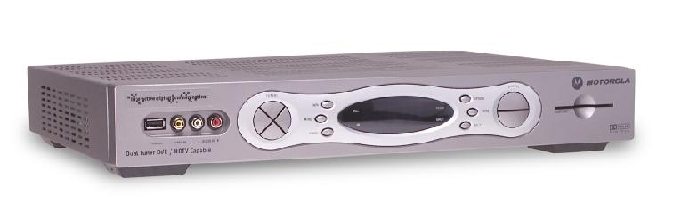
DCT 6412 HD DVR. Wiring Instructions. Additional Information. Digital Cable Box USER MANUAL
 DCT 6412 HD DV Wiring Instructions Additional Information Digital Cable Box USE MANUA CAUTION ISK OF EECTIC SHOCK DO NOT OPEN CAUTION: TO EDUCE THE ISK OF EECTIC SHOCK, DO NOT EMOVE COVE (O BACK). NO USE-SEVICEABE
IMPORTANT SAFETY INSTRUCTIONS
 REPAIRS If you find the unit in need of repair, call Motorola Support at 1-866-668-2271 or 1-866-MOT-BCS1 IMPORTANT SAFETY INSTRUCTIONS 1 Read these instructions. 2 Keep these instructions. 3 Heed all
User Guide. QIP2500 Series Set-Top Terminal
 User Guide QIP2500 Series Set-Top Terminal CAUTION RISK OF ELECTRIC SHOCK CAUTION: TO REDUCE THE RISK OF ELECTRIC SHOCK, DO NOT REMOVE COVER (OR BACK). NO USER-SERVICEABLE PARTS INSIDE. REFER SERVICING
OPERATION MANUAL DCH6200. User Guide
 OPERATION MANUAL DCH6200 User Guide IMPORTANT SAFETY INSTRUCTIONS Read these instructions. Keep these instructions. Heed all warnings. Follow all instructions. Do not use this apparatus near water. The
OPERATION MANUAL DCH6416. User Guide
 OPERATION MANUAL DCH6416 User Guide IMPORTANT SAFETY INSTRUCTIONS Read these instructions. Keep these instructions. Heed all warnings. Follow all instructions. Do not use this apparatus near water. Clean
OPERATION MANUAL DCH3416. User Guide
 OPERATION MANUAL DCH3416 User Guide IMPORTANT SAFETY INSTRUCTIONS Read these instructions. Keep these instructions. Heed all warnings. Follow all instructions. Do not use this apparatus near water. The
QIP7232 P2. Hybrid QAM/IP High-definition Set-top. Quick Start Guide
 QIP7232 P2 Hybrid QAM/IP High-definition Set-top Quick Start Guide Before You Begin Introduction Congratulations on receiving a Motorola QIP7232 Hybrid QAM/IP High-definition Set-top. This document will
HD Digital Set-Top Box Quick Start Guide
 HD Digital Set-Top Box Quick Start Guide Eagle Communications HD Digital Set-Top Box Important Safety Instructions WARNING TO REDUCE THE RISK OF FIRE OR ELECTRIC SHOCK, DO NOT EXPOSE THIS PRODUCT TO RAIN
Evolution Digital HD Set-Top Box Important Safety Instructions
 Evolution Digital HD Set-Top Box Important Safety Instructions 1. Read these instructions. 2. Keep these instructions. 3. Heed all warnings. 4. Follow all instructions. 5. Do not use this apparatus near
CAUTION RISK OF ELECTRIC SHOCK NO NOT OPEN
 Evolution Digital HD Set-Top Box Important Safety Instructions 1. Read these instructions. 2. Keep these instructions. 3. Heed all warnings. 4. Follow all instructions. 5. Do not use this apparatus near
USER GUIDE DCX3200. User Guide
 USER GUIDE DCX3200 User Guide IMPORTANT SAFETY INSTRUCTIONS Read these instructions. Keep these instructions. Heed all warnings. Follow all instructions. Do not use this apparatus near water. Clean only
Installation Manual VIP 1003
 Installation Manual VIP 1003 We Caring for the Environment by Recycling When you see this symbol on a Motorola product, do not dispose of the product with residential or commercial waste. Recycling your
INSTALLATION MANUAL VIP 1903 / VIP 1903 T VIP 1963 / VIP 1963 T
 INSTALLATION MANUAL VIP 1903 / VIP 1903 T VIP 1963 / VIP 1963 T We Declaration of Conformity Motorola Mobility, Inc. 101 Tournament Drive Horsham Pennsylvania 19044 USA declare under our sole responsibility
DCX3510-M High-Definition All-Digital Dual Tuner DVR Set-top
 User Guide DCX3510-M High-Definition All-Digital Dual Tuner DVR Set-top ARRIS Enterprises, Inc. 2014 All rights reserved. No part of this publication may be reproduced in any form or by any means or used
User Guide. DCX3220e. High-Definition Digital STB
 User Guide DCX3220e High-Definition Digital ST MOTOROLA and the Stylized M logo are trademarks or registered trademarks of Motorola Trademark Holdings, LLC. DOCSIS is a trademark or registered trademark
HD Digital MPEG2 Encoder / QAM Modulator Get Going Guide
 series HD Digital MPEG2 Encoder / QAM Modulator Get Going Guide HDb2640 HDb2620 HDb2540 HDb2520 The HDbridge 2000 Series is a combination HD MPEG 2 Encoder and frequency-agile QAM Modulator, all in a 1RU
HD Digital MPEG2 Encoder / QAM Modulator
 HD Digital MPEG2 Encoder / QAM Modulator HDMI In QAM Out series Get Going Guide ZvPro 800 Series is a one or two-channel unencrypted HDMI-to-QAM MPEG 2 Encoder / QAM Modulator, all in a compact package
HD Digital MPEG2 Encoder / QAM Modulator
 HD Digital MPEG2 Encoder / QAM Modulator YPrPb VGA In QAM Out series Get Going Guide ZvPro 600 Series is a one or two-channel Component or VGA-to-QAM MPEG 2 Encoder/ Modulator, all in a compact package
User Guide DCX3200-M P3. High-Definition Digital STB
 User Guide DCX3200-M P3 High-Definition Digital ST MOTOROLA and the Stylized M logo are trademarks or registered trademarks of Motorola Trademark Holdings, LLC. CableCARD TM, M-Card TM, and DOCSIS are
Connecting the Explorer 3300 Digital Home Communications Terminal
 User Guide Connecting the Explorer 3300 Digital Home Communications Terminal POWE VO CH+ VO+ SEECT GUIDE INFO EXIT CH SETTINGS Notice for CATV Installers CATV Installers Notice If you are a CATV installer,
Connecting the Explorer 8300TM Digital Video Recorder
 Connecting the Explorer 8300TM Digital Video ecorder Contents Safety Compliance Statements... iii Change the Way You Watch... Safety First... The Explorer eclub... Identify Your 8300... What s On the Front
ZvBox 150. HD video distribution over COAX Get Going Guide
 ZvBox 150 HD video distribution over COAX Get Going Guide ZvBox 150 is an HD MPEG 2 Encoder and frequency agile QAM Modulator. It allows you to convert any HD video source, Component or RGB (VGA), in real
USER GUIDE DCX525. All-Digital, High-Definition Set-top
 USER GUIDE DCX525 All-Digital, High-Definition Set-top ARRIS Enterprises, Inc. 2015 All rights reserved. No part of this publication may be reproduced in any form or by any means or used to make any derivative
User Guide. Connecting the Explorer 1850 Digital Home Communications Terminal
 User Guide Connecting the Explorer 1850 Digital Home Communications Terminal Notice for CATV Installers Notice for CATV Installers: If you are a CATV installer, read the information in the box below. 2
2.0 Wall Mount TV Soundbar Instruction Manual
 8010275 2.0 Wall Mount TV Soundbar Instruction Manual Read all of the instructions before using this soundbar and keep the manual in a safe place for future reference. Safety Information CA UT IO N RISK
CAUTION REPAIRS NOTE TO CATV SYSTEM INSTALLER EXAMPLE OF ANTENNA GROUNDING WARNING
 DCT700 User Guide CAUTION ISK OF ELECTIC SHOCK CAUTION: TO EDUCE THE ISK OF ELECTIC SHOCK, DO NOT EMOVE COVE (O BACK). NO USE-SEVICEABLE PATS SIDE. EFE SEVICG TO QUALIFIED SEVICE PESONNEL. EPAIS If you
 Register your product and get support at www.philips.com/welcome SWS3435S/27 SWS3435H/37 EN User manual Contents 1 Important 4 Safety 4 English 2 Your SWS3435 6 Overview 6 3 Installation 7 Connect the
User Guide. Connecting the Explorer 3350 Digital Home Communications Terminal
 User Guide Connecting the Explorer 3350 Digital Home Communications Terminal Notice for CATV Installers CATV Installers Notice If you are a CATV installer, read the information in the box below. CONTENTS
Operating Instructions
 Operating Instructions SDI Input board Model No. AV-HS04M1 РУССКИЙ FRANÇAIS DEUTSCH ENGLISH ESPAÑOL ITALIANO Before operating this product, please read the instructions carefully and save this manual for
Display Displays channel number and time of day. Message Lights when a message is waiting OPTIONS MSGS. Power Indicator Lights to indicate DCT is on
 Motorola DCT6208 Audio In (L/R) Connects to a CD player or stereo tuner Cursor Moves cursor around program guide and menu screens Info Displays current channel and program info Display Displays channel
Introduction. Important Safety Instructions
 Introduction Congratulations on purchasing your Eviant Portable Digital TV. On June 12, 2009 the conversion to digital television broadcasting will be complete all throughout the United States and Puerto
HDMI 5x1 Switch B-240-HDSWTCH-5X1 INSTALLATION MANUAL
 HDMI 5x1 Switch B-240-HDSWTCH-5X1 INSTALLATION MANUAL IMPORTANT SAFETY INSTRUCTIONS To reduce the risk of fire or electric shock, read and follow all instructions and warnings in this manual. Keep this
Register your product and get support at SDV5122/27. EN User manual
 Register your product and get support at www.philips.com/welcome SDV5122/27 User manual Contents 1 Important 4 Safety 4 Notice for USA 5 Notice for Canada 5 Recycling 6 English 2 Your SDV5122 7 Overview
HD709N INSTRUCTIONS MANUAL IPTV MEDIA PLAYER.
 INSTRUCTIONS MANUAL IPTV MEDIA PLAYER www.zaaptv.com 2. Contents 1. Cover 1 2. Contents 2 3. Safety Information 3 4. Device Introduction 7 5. Connecting your Device 10 6. Setting up your Device 11 7. Basic
Congratulations on purchasing your Eviant Portable Digital TV.
 Introduction Congratulations on purchasing your Eviant Portable Digital TV. On June 12, 2009 the conversion to digital television broadcasting will be complete all throughout the United States and Puerto
4 PORT HDMI SWITCH
 4 PORT HDMI SWITCH 1518896 IMPORTANT SAFEGUARDS OF HDMI SWITCH PRODUCTS PLEASE READ CAREFULLY THE FOLLOWING SAFEGUARDS THAT ARE APPLICABLE TO YOUR EQUIPMENT 1. Read instructions - All the safety and operating
PACE DC700X SET-TOP CUSTOMER SERVICE AND INSTALLATION GUIDE
 PACE DC700X SET-TOP CUSTOMER SERVICE AND INSTALLATION GUIDE Manufactured under license from Dolby Laboratories. Dolby and the double-d symbol are trademarks of Dolby Laboratories. This product incorporates
ATTACHING & REMOVING THE BASE
 TV53DB ATTACHING & REMOVING THE BASE 1. To install or remove the neck, screw in or remove the 4 screws indicated in the picture. 2. To install the base, place the display unit flat on a table. Afterwards
TelergyT-503. User s Guide. How to use this T-503 set-top box
 TelergyT-503 User s Guide How to use this T-503 set-top box IMPORTANT SAFETY INSTRUCTIONS Read and follow these instructions. Heed all warnings. Do not use this apparatus near water. Clean only with dry
Home Entertainment Server
 Explorer 8000HD Home Entertainment Server User s Installation Guide In This Guide Safety Information... 2 Introduction... 4 What s On the Front Panel?... 5 What s On the Back Panel?... 6 HDTV vs SDTV...
Connecting the. Explorer 8300HDTM Digital Video Recorder
 Connecting the Explorer 8300HDTM Digital Video ecorder Contents Safety Compliance Statements... iv Change the Way ou Watch TV... 1 Safety First... 1 The Explorer eclub... 1 Identify our 8300HD... 1 What
HDBaseT RECEIVER B-520-RX-330-IR INSTALLATION MANUAL
 HDBaseT RECEIVER B-520-RX-330- INSTALLATION MANUAL IMPORTANT SAFETY INSTRUCTIONS To reduce the risk of fire or electric shock, read and follow all instructions and warnings in this manual. Keep this manual
USER GUIDE Pace RNG150N / RNG200N
 USER GUIDE Pace RNG150N / RNG200N BRINGING TECHNOLOGY HOME www.pace.com CONTENTS This guide covers both the RNG150N and the RNG200N set-tops. They are very similar, but the RNG200N has an internal hard
HDBaseT RECEIVER B-520-RX-230-IR INSTALLATION MANUAL
 HDBaseT RECEIVER B-520-RX-230-IR INSTALLATION MANUAL IMPORTANT SAFETY INSTRUCTIONS To reduce the risk of fire or electric shock, read and follow all instructions and warnings in this manual. Keep this
2.4 GHz WIRELESS VIDEO SENDER SYSTEM MODEL: VS6234
 2.4 GHz WIRELESS VIDEO SENDER SYSTEM MODEL: VS6234 Please read this manual thoroughly before operating this system OPERATING INSTRUCTIONS 03/02 1 SAFETY INSTRUCTIONS CAUTION! RISK OF ELECTRIC SHOCK. DO
HDBaseT RECEIVER B-540-RX-330-IR INSTALLATION MANUAL
 HDBaseT RECEIVER B-540-RX-330-IR INSTALLATION MANUAL IMPORTANT SAFETY INSTRUCTIONS To reduce the risk of fire or electric shock, read and follow all instructions and warnings in this manual. Keep this
DCT2000. User Guide CU RSOR CHAN NEL POWER GUIDE INFO A/B
 DCT2000 User Guide CU RSOR MESSAGES REMOTE CHAN NEL A/B POWER GUIDE FO MENU SELECT A/B POWER CAUTION RISK OF ELECTRIC SHOCK CAUTION: TO REDUCE THE RISK OF ELECTRIC SHOCK, DO NOT REMOVE COVER (OR BACK).
EXPLORER Digital Home Communications Terminal. User s Installation Guide
 EXPOE Digital Home Communications Terminal User s Installation Guide IMPOTANT UES FO SAFE OPEATION Note to the Installer Note to CATV System Installer This reminder is provided to call the CATV system
USER GUIDE Pace TDC788D
 USER GUIDE Pace TDC788D BRINGING TECHNOLOGY HOME www.pace.com CONTENTS SAFETY INFORMATION...3 REAR PANEL...6 CONNECTING THE EQUIPMENT...7 Setup A - Home theater system with HDTV (HDMI connection)...8 Setup
IPSTB1200 /IPC3200 Media Client User guide
 IPSTB1200 /IPC3200 Media Client User guide Safety/Compliance Important Safety Instructions Please carefully read these safety and compliance instructions and this entire user guide. Follow all instructions
Guide to Using Your Digital Video Recorder in Stand-Alone Mode. User Guide
 Guide to Using Your Digital Video ecorder in Stand-Alone Mode User Guide Notice to Installers The servicing instructions in this notice are for use by qualifi ed service personnel only. To reduce the risk
OPERATOR S MANUAL Pace RNG110
 OPERATOR S MANUAL Pace RNG110 BRINGING TECHNOLOGY HOME www.pace.com CONTENTS SAFETY INFORMATION...3 REAR PANEL...6 CONNECTING THE EQUIPMENT...7 Setup A - Home theater system with HDTV (HDMI connection)...7
Monochrome Video Monitors
 Instructions for Use Monochrome Video Monitors En F D E NL I LTC 2009 LTC 2012 LTC 2017 Philips Communication & Security Systems GB F D E NL I Instructions for Use...1.1 Mode d emploi...2.1 Bedienungsanleitung...3.1
ZVOX AccuVoice TV Speaker Model AV203
 ZVOX AccuVoice TV Speaker Model AV203 SETUP & OPERATION www.zvoxaudio.com 2 ZVOX AccuVoice TV Speaker Setup & Operation READ THIS FIRST Important Safety Instructions For ZVOX Audio System WARNING TO PREVENT
ZVOX AccuVoice TV Speaker Model AV203
 ZVOX AccuVoice TV Speaker Model AV203 SETUP & OPERATION www.zvoxaudio.com READ THIS FIRST Important Safety Instructions For ZVOX Audio System WARNING TO PREVENT FIRE OR SHOCK HAZARD, DO NOT EXPOSE THIS
VIZIO. QUICK START GUIDE Model: E390-B1
 VIZIO QUICK START GUIDE Model: E390-B1 IMPORTANT SAFETY INSTRUCTIONS Your TV is designed and manufactured to operate within defined design limits. Misuse may result in electric shock or fire. To prevent
Amulet 4. Quick Start Guide
 Amulet 4 Media Recorder Table of Contents Overview 2 Safety Instructions 4 What s Included 6 Front Panel 7 Rear Panel Connecting Video 8 High-Definition TVs 9 Standard-Definition TVs Connecting Audio 11
Connecting the Explorer. 8300HDC TM Digital Video Recorder
 Connecting the Explorer 8300HDC TM Digital Video ecorder 1 What s on the Front Panel? EXPOE 8300HDC CH + GUIDE POWE VO - VO + FO CH - EXIT SEECT IST AUX PUT 1 2 3 4 5 6 7 8 9 10 11 12 T12141 1 Power Turns
USER GUIDE Pace Xi3 PX031ANI. BRINGING TECHNOLOGY HOME
 USER GUIDE Pace Xi3 PX031ANI BRINGING TECHNOLOGY HOME www.pace.com This product incorporates copyright protection technology that is protected by U.S. patents and other intellectual property rights. Use
USER MANUAL. 27 Full HD Widescreen LED Monitor L27ADS
 USER MANUAL 27 Full HD Widescreen LED Monitor L27ADS TABLE OF CONTENTS 1 Getting Started 2 Control Panel/ Back Panel 3 On Screen Display 4 Technical Specs 5 Care & Maintenance 6 Troubleshooting 7 Safety
SW 50. Powered Subwoofer with Built-in Stereo Crossover
 Owner s Manual SW 50 ed Subwoofer with Built-in Stereo Crossover Congratulations on your new purchase and welcome to the AudioSource family of satisfied customers. We trust you will continue to enjoy the
Kamai 4 Media Receiver. Quick Start Guide
 Kamai 4 Media Receiver Table of Contents Overview 2 Safety Instructions 4 What s Included 6 Front Panel 7 Rear Panel connecting Video 8 High-Definition TVs 9 Standard-Definition TVs connecting Audio 11
KD-CSW2x1. Operating Instructions. 2 Inputs to 1 Output Component Video/Audio Switcher. KD-CSW2x1 Operating Instructions.
 KD-CSW2x1 2 Inputs to 1 Output Video/ Switcher Operating Instructions Key Digital, led by digital video pioneer Mike Tsinberg, develops and manufactures high quality, cutting-edge technology solutions
Call DIGITAL QUICK START.
 DIGITAL QUICK START Your easy-to-follow guide to setting up Charter Business Digital Cable TV SCIENTIFIC ATLANTA HD EXP300HD/EXP350HD/ EXP800HD/EXP8300HD Charter Business Digital Cable TV SELF-STALL GUIDE
28 4K LED monitor. User Manual M284K
 28 4K LED monitor User Manual M284K CONTENTS Safety Information... 2 What s included..... 4 Getting Started....... 8 Troubleshooting.... 14 Specification.... 15 2 of 15 SAFETY INFORMATION Read these instructions
55" Curved Ultra HD LED TV User s Guide for Model TU5587B v For the most up-to-date version of this User s Guide, go to
 55" Curved Ultra HD LED TV User s Guide for Model TU5587B v1922-01 For the most up-to-date version of this User s Guide, go to www.gpx.com Safety Instructions & Warnings CAUTION RISK OF ELECTRIC SHOCK
 Register your product and get support at www.philips.com/welcome SWW1890 User manual Contents 1 Important 4 Safety 4 English 2 Your Philips Wireless HD Net Connect 5 What is in the box 5 3 Overview 6
English. User Manual sub8 Subwoofer SUBWOOFER. Supporting your digital lifestyle
 English User Manual sub8 Subwoofer U SUBWOOFER Supporting your digital lifestyle Table of Contents Important Safety Precautions........ 2 Introduction / What s in the Box?...... 3 Front & Rear Panels............
CANADIAN POSTAGE REQUIRED. A Division of ZAPiT Games Inc. P.O. Box 239 Mississauga, Ontario Canada L4T 3B6 INSTRUCTION MANUAL.
 CANADIAN POSTAGE EQUIED A Division of ZAPiT Games Inc. P.O. Box 239 Mississauga, Ontario Canada 4T 3B6 INSTUCTION MANUA www.playgamewave.com 2 GAME WAVE PAYE 2 5 o 4 DEGEES 4 1 3 INCUDES EVEYTHING YOU
USER GUIDE Pace PX022ANx
 USER GUIDE Pace PX022ANx BRINGING TECHNOLOGY HOME www.pace.com CONTENTS SAFETY INFORMATION...3 IMPORTANT SAFETY INSTRUCTIONS...3 Regulatory information...5 REAR PANEL...6 CONNECTING THE EQUIPMENT...7 Setup
E246 Series User Guide
 E246 Series User Guide PACKAGE CONTENTS SCEPTRE Display x 1 Display Base x 1 Display Neck x 1 Screws x 6 (ST3 x 10mm) Warranty Card x 1 Power Cord x 1 (Attached) Display Remote Control (AAA Batteries included)
Check our knowledge base at
 USER MANUAL Check our knowledge base at www.paralinx.net/support Copyright 2015 Paralinx LLC All Rights Reserved TABLE OF CONTENTS 1 Important Notice 10 LCD Screen 2 Safety Instructions 11 Indicators 3
E325 Series User Guide
 E325 Series User Guide PACKAGE CONTENTS SCEPTRE Display x 1 Display Base x 1 Thick Threaded Screws x 3 Thin Threaded Screws x 4 Circular Metal Plate x 1 Black Plastic Ring x 1 Power Cord x 1 (Attached)
LED TV MODEL NO.: NE22K5BG. Please read this manual carefully before installing and operating the TV. Keep this manual handy for further reference
 LED TV USER MANUAL MODEL NO.: NE22K5BG IMPORTANT Please read this manual carefully before installing and operating the TV. Keep this manual handy for further reference Table Of Contents Preparations Guide
User Guide Pace PXD10ANI
 User Guide Pace PXD10ANI BRINGING TECHNOLOGY HOME www.pace.com CONTENTS SAFETY INFORMATION...3 IMPORTANT SAFETY INSTRUCTIONS...3 Regulatory information...5 REAR PANEL...6 CONNECTING THE EQUIPMENT...7 Setup
Full High Definition LCD TV USER MANUAL
 1080p3 LCD TV Full High Definition LCD TV 1080p3 USER MANUAL Important Safety Precautions Important Safety Precautions 1 CAUTION RISK OF ELECTRIC SHOCK DO NOT OPEN This symbol indicates important instructions
Kamai 6 Media Receiver. Quick Start Guide
 Kamai 6 Media Receiver Table of Contents Overview 2 Safety Instructions 4 What s Included 6 Front Panel 7 Rear Panel Connecting Video 8 High-Definition TVs 9 Standard-Definition TVs Connecting Audio 10
MONOPRICE. Multiformat to SDI Converter with Scaler. User's Manual P/N 15775
 MONOPRICE Multiformat to SDI Converter with Scaler P/N 15775 User's Manual SAFETY WARNINGS AND GUIDELINES This device is intended for indoor use only. Do not expose this device to water or moisture of
MONOPRICE. SDI to Multiformat Video Converter with Scaler. User's Manual P/N 15776
 MONOPRICE SDI to Multiformat Video Converter with Scaler P/N 15776 User's Manual SAFETY WARNINGS AND GUIDELINES This device is intended for indoor use only. Do not expose this device to water or moisture
User Instructions. 16 SCB Sync Station.
 User Instructions 16 SCB Sync Station Contents Overview... 1 Specifications... 1 Compliance and approvals... 2 Safety instructions... 3 Set up... 4 How to charge multiple devices... 4 How to synchronize
Amulet 6. Quick Start Guide
 Amulet 6 Media Recorder Table of Contents Overview 2 Safety Instructions 4 What s Included 6 Front Panel 7 rear Panel Connecting Video 8 High-Definition TVs 9 Standard-Definition TVs Connecting Audio 10
Disclaimer. Trademarks. Copyright. Contact Us Control4 Corporation S. Election Road Salt Lake City, UT USA
 Disclaimer Trademarks Copyright Control4 makes no representations or warranties with respect to this publication, and specifically disclaims any express or implied warranties of merchantability or fitness
DisplayPort Extender over 2 LC Fibers
 DisplayPort Extender over 2 LC Fibers Audio 3GSDI Embedder EXT-DP-CP-2FO User Manual Release A2 DisplayPort Extender over 2 LC Fibers Important Safety Instructions 1. Read these instructions. 2. Keep these
Disclaimer. Warning and Caution CAUTION!
 Disclaimer While every effort has been made to ensure that the information contained in this guide is accurate and complete, no liability can be accepted for any errors or omissions NUVICO reserves the
AITech ProA/V Media Extender 5GHz Digital
 AITech ProA/V Media Extender 5GHz Digital 5 GHz Wireless Digital Media Transmitter and Receiver User Manual Table of Contents 1. Package Contents 2. Panels and Functions AV Sender AV Receiver 3. Setup
LCD VALUE SERIES (32 inches)
") LCD VALUE SERIES (32 inches) http://www.orionimages.com All contents of this document may change without prior notice, and actual product appearance may differ from that depicted herein 1. SAFETY INSTRUCTION
LCD VALUE SERIES (32 inches) http://www.orionimages.com All contents of this document may change without prior notice, and actual product appearance may differ from that depicted herein 1. SAFETY INSTRUCTION
VIZIO MODELS E320AR E420AR QUICK START GUIDE FULL USER MANUAL AVAILABLE AT VIZIO.COM
 MODELS E320AR E420AR VIZIO QUICK START GUIDE FULL USER MANUAL AVAILABLE AT VIZIO.COM IMPORTANT SAFETY INSTRUCTIONS Your TV is designed and manufactured to operate within defined design limits. Misuse may
Welcome to NEED HELP? DIRECTV offers the best entertainment experience. Use this guide to make the most of it LKR FCC ID : ORS
 NEED HELP? Important Tips Do not unplug your receiver If you unplug it you may miss the most recent updates that improve our service. The DIRECTV receiver is designed to consume very little energy while
17 19 PROFESSIONAL LCD COLOUR MONITOR ART
 17 19 PROFESSIONAL LCD COLOUR MONITOR ART. 41657-41659 Via Don Arrigoni, 5 24020 Rovetta S. Lorenzo (Bergamo) http://www.comelit.eu e-mail:export.department@comelit.it WARNING: TO REDUCE THE RISK OF FIRE
Utility Amplifier GA6A Model
 Utility Amplifier GA6A Model Installation and Use Manual 2004 Bogen Communications, Inc. All rights reserved. Specifications subject to change without notice. 54-5757-03D 1503 NOTICE: Every effort was
XFINITY TV UNIVERSAL DIGITAL TRANSPORT ADAPTER User Guide
 XFINITY TV UNIVERSAL DIGITAL TRANSPORT ADAPTER User Guide UDTA USER SIK 1011.indd 1 Contents 3 Welcome to XFINITY TV 4 Using Your Remote Control 5 Troubleshooting and FAQs 6 The Comcast Customer Guarantee
VIZIO MODELS. n E191VA n E221VA QUICK START GUIDE HD PICTURE SLIM DESIGN LED FULL USER MANUAL AVAILABLE AT VIZIO.COM
 MODELS n E191VA n E221VA VIZIO QUICK START GUIDE HD PICTURE SLIM DESIGN LED FULL USER MANUAL AVAILABLE AT VIZIO.COM IMPORTANT SAFETY INSTRUCTIONS Your TV is designed and manufactured to operate within
USER MANUAL. 22" Class Slim HD Widescreen Monitor L215DS
 USER MANUAL 22" Class Slim HD Widescreen Monitor L215DS TABLE OF CONTENTS 1 Getting Started Package Includes Installation 2 Control Panel / Back Panel Control Panel Back Panel 3 On Screen Display 4 Technical
DisplayPort Extender over 2 LC Fibers
 DisplayPort Extender over 2 LC Fibers Audio 3GSDI Embedder EXT-DP-CP-2FO User Manual Release A2 DisplayPort Extender over 2 LC Fibers Important Safety Instructions 1. Read these instructions. 2. Keep these
VIZIO. QUICK START GUIDE Model: E280-A1
 VIZIO QUICK START GUIDE Model: E280-A1 IMPORTANT SAFETY INSTRUCTIONS Your TV is designed and manufactured to operate within defined design limits. Misuse may result in electric shock or fire. To prevent
HDBaseT EXTENDER B-540-EXT-230-RS INSTALLATION MANUAL
 EXTENDER B-540-EXT-230-RS INSTALLATI MANUAL IMPORTANT SAFETY INSTRUCTIS To reduce the risk of fire or electric shock, read and follow all instructions and warnings in this manual. Keep this manual for
DDW36C Advanced Wireless Gateway - Safety and Installation Product Insert. Federal Communications Commission (FCC) Interference Statement
 Interference Statement") DDW36C Advanced Wireless Gateway - Safety and Installation Product Insert Federal Communications Commission (FCC) Interference Statement This equipment has been tested and found to comply with the limits
DDW36C Advanced Wireless Gateway - Safety and Installation Product Insert Federal Communications Commission (FCC) Interference Statement This equipment has been tested and found to comply with the limits
Personal Q Guide for VENUE Systems
 Personal Q Guide for VENUE Systems Version 1.0 Digidesign 2001 Junipero Serra Boulevard Daly City, CA 940-3886 USA tel: 650 731 6300 fax: 650 731 6399 Technical Support (USA) tel: 650 731 6100 fax: 650
ZXV10 B760H ZXV10 B760E RichMedia Box User Guide
 ZTE CORPORATION NO.55,Hi-techRoadSouth,ShenZhen,P.R.China Postcode:518057 Tel: (86) 755 26771900 800-9830-9830 Fax: (86) 755 26772236 URL: http://support.zte.com.cn E-mail: doc@zte.com.cn ZXV10 B760H ZXV10
MONOPRICE. BitPath AV HDMI Extender over Single Cat6 Cable, 120m. User's Manual P/N 16228
 MONOPRICE BitPath AV HDMI Extender over Single Cat6 Cable, 120m P/N 16228 User's Manual SAFETY WARNINGS AND GUIDELINES Please read this entire manual before using this device, paying extra attention to