DIY KIT MHZ 8-DIGIT FREQUENCY METER
|
|
|
- Scot Woods
- 5 years ago
- Views:
Transcription
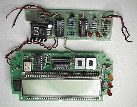
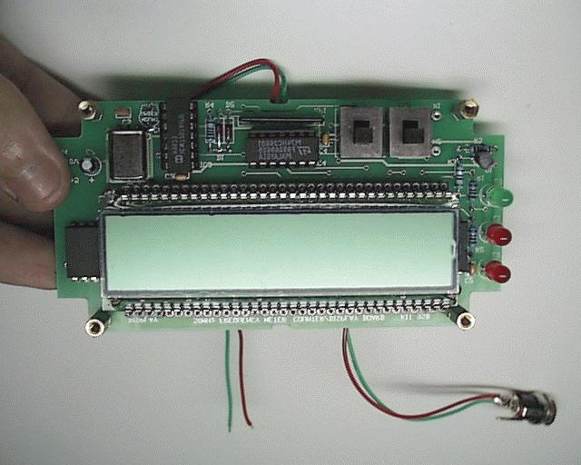
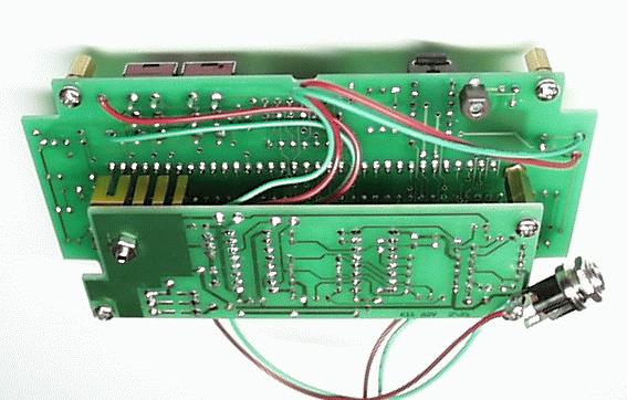
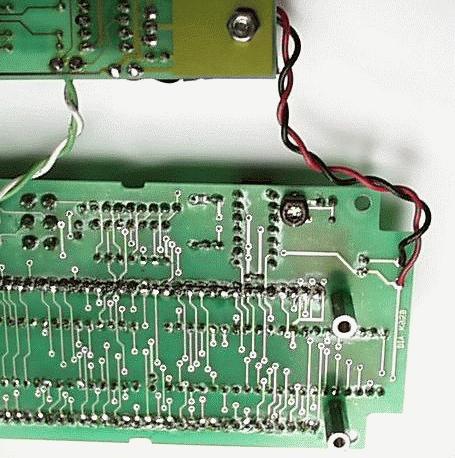
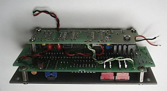
1 This kit is a stand-alone frequency meter capable of measuring repetitive signals up to a frequency of 50MHz. It has two frequency ranges (15 and 50 MHz) as well as two sampling rates (0.1 and 1 second). Output is via an 8- digit LCD display. Nominal input impedance is 1MΩ. The kit is supplied with a small plastic case complete with a screen-printed front panel. It requires a 9-to-12V DC power supply. A standard plug pack, centre positive, can be used. Current consumption is approximately 175mA. Case dimension: 13 x 7 x 4 cm. The kit is constructed on two printed circuit boards (PCBs). One is double-sided, through-hole-plated and the other is single-sided. Both PCBs have a component overlay for ease of assembly. Protel Autotrax & Schematic were used to design the boards. ASSEMBLY INSTRUCTIONS Follow the component overlay on the PCBs for placement of components. Some components such as the transistors, FET and small signal diodes look the same so identify first them before starting. Take care with the metal film resistors the color bands are difficult to distinguish. If in doubt use a meter to measure the resistance. Interface Board Assembly is straightforward. Start with the lowest height components (resistors, diodes, etc). Note: There are five (5) links that need to be installed. These should be added before the IC sockets. Use the wire offcuts from the resistors as the links. Fix the 5V regulator and heatsink to the PCB using the nut and bolt provided. When inserting diodes D3-6, space them up from the PCB by about 3mm (1/8 ). This will help with heat dissipation. Display Board The order in which components are fitted is critical. The following order is recommended: 1. Socket strip for the LCD display. Before soldering flip the board over and lay it on the table so that the socket strips are fully seated and vertical. 2. Resistors and diodes. 3. Resistor network RP1. The dot on one end of the body goes where the square is marked on the overlay. 4. The two 40-pin ICs, IC1 & IC2. These are soldered directly to the PCB. Do not use IC sockets. 5. The two 14-pin IC sockets for IC3 & IC4. Fit the ICs. 6. Capacitors. Note that the trimcap, C6, is mounted on the solder side of the board. This allows easy access for adjustment later on. 7. Crystal and transistor. 8. Bolt the three (3) 15mm brass spacers to the solder side of the display board. The three holes are located next to the 40-pin ICs. 9. Bolt the four (4) 10mm brass spacers to the component side of the display board. The four holes are located on each of the corners. 10. First identify which way around the LCD display is to be inserted into the socket strips. There is a small dimple at one end of the LCD. This end goes to the right side of the board, near where the LEDs will be fitted. Be careful when pushing the LCD into the socket strip. Make sure that the pins are all lined up in the holes. You will not be able to push all the pins in at once. Do one row at a time starting at one end. Apply even pressure along the row of pins until they are all in. Excessive force could damage the LCD. Keep watching for any pins starting to bend. Repeat for the other row. 11. Next is the LEDs. They have to be spaced up from the board so that they protrude slightly through the front panel. The easiest way to get the correct height is to use the front panel as a guide. Fit the LEDs into place but do not solder them in yet. Mount the front panel to the display board on the 10mm spacers and screw into place. Turn the assembly over onto a flat surface so that the front panel is down. Position the LEDs so that they drop through the holes in the front panel and solder them into place. 12. The only thing left to mount are the slide switches. Remove the front panel and insert the switches. Make sure they are sitting down against the PCB and evenly aligned with the overlay before soldering. It may be best to solder just one pin on each switch and then mount the front panel again. Check that the switch levers protrude through the front panel and slide freely without fouling. If all is well then solder the rest of the switch pins. Putting it all together Use the wiring diagram on the following page as a guide. There are four wires that connect the two PCBs together, two power (X3,4) and two signal (X1,2). Cut and strip two pieces of wire 10cm (4 ) long. Solder one end of each wire to pins X3 and X4 on the interface board. Cut and strip another two pieces 8cm (3 ) long. Solder one end of each wire to pins X1 and X2 on the interface board The other wires are for the DC input power and signal. Cut and strip four pieces of wire 9cm (3.5 ) long. Solder one end of each wire to pins IN1, IN2, V1 and V2 on the interface board. The two boards can now be bolted together, with the Interface board fitted beneath the Display board. Fit and solder the four wires, X1-4, from the Interface board to their corresponding points on the Display board. The wires are inserted on the solder side of the display board and soldered from the component side. Snip off any excess. PAGE 1
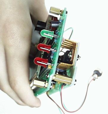
2 We are now ready to drill the mounting holes for the BNC connector and DC power jack. The positioning of the holes is critical so that the connectors do not touch the PCBs inside the case. Both connectors are mounted on the ends of the case. Looking from the front, the BNC connector mounts on the left side and the power jack on the right. Refer to the diagrams on page 4 for hole sizes and position details. Fit the BNC connector and power jack into the holes and secure them. All that remains is to connect the BNC connector and DC power jacks and fit the whole assembly into the case. The wires connected to IN1 and IN2 connect to the BNC input connector, with IN1 connecting to the centre pin. The wires connected to V1(+) and V2(-) connect to the power jack, with V1 connecting to the centre pin. Proceed to the Testing and Calibration sections before final assembly. Wiring Diagram PAGE 2 Position the whole assembly into the case, making sure that the wires are clear of the heatsink. Use the four (4) self-tapping screws to secure it to the case. TESTING Before applying power, check your wiring and assembly very carefully. Make sure that polarity sensitive components such as diodes, transistors, ICs and electrolytic capacitors are inserted correctly. If everything seems OK, connect a 9-to-12V DC plug pack to the power input socket. The LCD display should spring to life. The Gate LED should be flashing and one of the other two LEDs should also be on. With the signal input floating it is very likely that the display will show a random reading due to stray RF pickup. If the unit appears dead then check the 5 volt output from the regulator. If there is no 5 volts there, check the input to the regulator. It should be greater than 7.5 volts. If there is no voltage there at all, check the polarity of the plug pack - it should be centre positive. Are diodes D3-6 inserted the right way around? It you get a reading but it is less than 7.5 volts then you may need a higher voltage
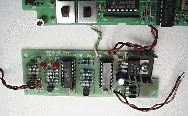
3 plug pack or you may need to strap out some of the diodes. See next section Calibration for details. If the voltage at the input to the regulator seems OK, then it is probable that there is a short from the 5 volt supply to ground. Disconnect the display board and check if that isolates the fault. Once you have determined which board has the fault, check it for shorts between the PCB tracks themselves. Look for solder bridges between component pins. If all still looks OK then start taking out the 100nF decoupling capacitors across each of the ICs. These have been known to go short circuit. Another possibility is that the regulator is faulty, although this is unlikely. If all seems well then the next thing to do is connect it to a repetitive signal source. A frequency generator or the calibration output of a CRO will do fine. Check that you get a reading on the display. If not, check the signal on X1 and X2, using either a CRO or a logic probe. If there is no signal on those pins then the fault is on the interface board. CALIBRATION The only calibration required is to adjust trimcap C6 to set the gating signal output of IC3. The easiest way of doing this is to measure the frequency of a known signal source, such as the timebase signal from a commercial counter or that from a crystal calibrator. In either case, simply adjust C6 to produce the correct reading. The only other adjustment is to set the input voltage to the regulator. The kit draws about 150-to-175mA. With a minimum voltage drop across the regulator of 2.5 volts, the regulator will dissipate between 350 and 450mW. Obviously a larger drop across the regulator will result in higher power dissipation. In order to keep the power dissipation of the regulator to a minimum, a number of diodes (D3-6) have been added in series with the input. Each diode drops approximately 0.7 volts, for a total of 2.8 volts. This helps to reduce the input voltage to the regulator and therefore its power dissipation. Of course each diode will dissipate some of the power that would have been dissipated by the regulator. Depending on the output from the plug pack used, it may be necessary to strap out some of these diodes in order to lift the input voltage of the regulator to the minimum 7.5 volts required. This is easily done by soldering a small wire link on the solder side of the PCB beneath diodes D3, D4 and/or D5. Pads have been provided for this purpose. Use the lowest voltage plug pack available which is capable of delivering the minimum 7.5 volts at the input of the regulator. A 9V plug pack should be fine. CIRCUIT DESCRIPTION The circuit has been divided into two sections, the Interface board and the Display/Counter board. Interface Board This section consists of two parts, a FET buffer stage (Q1) followed by a wideband preamp and squaring circuit, using an ECL triple line receiver (IC1). Q1 is used to provide a high impedance input. Resistor R1 and diodes D1 and D2 form an input clipping circuit to protect the FET from damage due to large input signals. The diodes are type BAW62, which have high switching speeds and low parallel capacitance. Capacitor C1 is used to block DC. C2 provides high frequency compensation. A word about the input impedance. This is nominally 1MΩ (R2) in parallel with about 10pF. This 10pF is made up of the capacitance of the FET and diodes D1 and D2. This capacitance affects the input impedance of the meter. The higher the input frequency the lower the capacitive reactance and therefore the lower the input impedance. At 50 MHz the capacitive reactance is only 318 ohms! This is the reason why commercial frequency meters have a separate input for measuring frequencies above 50 MHz, using prescaler chips that have a nominal input impedance of 50Ω. All high frequency circuits use 50Ω inpedance to minimise the effect of stray capacitance. The first two stages of IC1 are configured as wideband amplifiers, while the third stage is configured as a Schmitt trigger with hysteresis. Transistors Q2 and Q3 act as level translators between the small output voltage swing from the ECL amplifier stage and the CMOS counting section. The counters used (7224) will operate up to 15 MHz directly. However higher frequencies must be prescaled first. This is the function of IC3 (74F160), a BCD decade counter. An F series part was used here. These parts will work up to 100 MHz. IC3 divides-down the signal by ten, allowing frequencies above 15MHz to be measured. Of course, prescaling the input signal reduces the resolution of the meter to 10Hz. The interface board also contains the power supply circuit. This is a standard 5 volt regulator with the usual input and output capacitors. A series of diodes on the input allow the voltage from the plug pack to be reduced before reaching the regulator. Diodes D3-5 can be strapped out to vary this input voltage. D6 cannot be strapped out and so provides protection for the regulator in case the input polarity is reversed. Display/Counter Board This is a classic textbook circuit straight out of the Harris Semiconductor data book. The circuit is based around an ICM7224, which is a 4 1/2 digit LCD Display counter. Two of these devices, IC1 and IC2, are used in series to provide an 8-digit counter. PAGE 3


4 The counter is capable of direct static counting, guaranteed from DC to 15 MHz. At normal ambient temperatures it will typically count up to 25 MHz. The counter is controlled via three inputs, RESET, STORE and COUNT INHIBIT. These inputs are directly interfaced to IC3, an ICM7207A CMOS Timebase Generator. The GATE signal from IC3 is inverted by Q1 and used to drive the COUNT INHIBIT input of IC2, the first counter in the chain. This signal can be set via the RANGE input to either 0.1 or 1 second. Q1 also drives the Sample Rate LED on the front panel. SW1 is the range switch. One half, SW1:B, is used to connect the direct or prescaled signal from the interface board to the counters. The other half, SW1:A, is used to drive the KHz or MHz LEDs of the front panel, as well as selecting the correct decimal point on the LCD display. To light an LCD segment, it is necessary to supply a signal to it that is 180 degrees out of phase with the COM or backplane signal. The individual digit segments are driven directly by IC1 and IC2. The decimal points are driven by IC4, a quad dual-input exclusive NOR gate. The COM signal from the counters is commoned to one of each of the gate inputs. The other gate inputs are normally pulled high by RP1. A high input allows the COM signal to pass through unchanged. A low input causes the COM signal to become inverted on its output and therefore light the corresponding decimal point. The decimal point selected depends on the position of the two switches, SW1 and SW2. DC Jack at LED end PAGE 4
5 PARTS LIST - K95 GENERAL PARTS LIST - K95B DISPLAY/COUNTER BOARD Plastic case, 129 x 68 x 41 mm... 1 BNC connector, panel mounting mm DC jack, panel mounting... 1 Front panel, K95C... 1 Metal spacer, 3mm tapped, 10mm long... 4 Metal spacer, 3mm tapped, 15mm long... 3 Flat washer, 3mm x 6mm screws Hookup wire, 2 colors, 30 inches of each color PARTS LIST - K95A INTERFACE BOARD Resistors (0.25W, 1%, Metal Film) 12...R R R R6-9, R12, K...R3-5, R K...R M...R Capacitors 150pF ceramic...c nF monoblock...c1, C4, C6-8, C uF 16V tantalum...c3, C uF 25V electro...c Semiconductors 1N D BAW62...D1, N4258, PNP transistor...q2, (or PN3640) 2N5486, N channel FET...Q F160...IC BCD decade counter MC IC ECL triple line receiver 7805 regulator, TO IC Miscellaneous 16-pin IC socket...ic1, K95A PCB... 1 Heatsink for 7805 regulator x 10mm screw & nut 1 Resistors (0.25W, 1%, Metal Film) R R1, K... R4, K 9P8R A RESNET... RP1...1 Capacitors 39pF ceramic... C nF monoblock... C pF trimcap... C uF 16V electro... C7...1 Semiconductors 1N D1,2...2 BC547B... Q1...1 ICM7224IPL... IC1, /2 digit LCD Display Counter ICM7207A... IC3...1 CMOS Timebase Generator 74HC IC4...1 Quad 2-inpt exclusive NOR gate LED, 5mm Red... L1,2...2 LED, 5mm Green... L3...1 Miscellaneous Crystal, MHz... Y1...1 Slide switch, DPDT... SW1,2...2 C&K, 1201-M2-C 8-digit display... DISPLAY...1 Varitronix, VI-804-DP-RC 14-pin IC socket... IC3, way socket strip... for LCD display...2 REFERENCES The Internet is the place to get references and any sort of technical data. Data sheets for the ICM7224 and ICM7207A are available from the Harris Semiconductor web site at:- Data for the 74HC266 and 74F160 can be found in any TTL data book. Functionally they are identical to the LS series of parts except that the F series part will operate at much higher frequencies. PAGE 5
6 PAGE 6
7 PAGE 7
8 PAGE 8
N3ZI Digital Dial Manual For kit with Serial LCD Rev 3.04 Aug 2012
 N3ZI Digital Dial Manual For kit with Serial LCD Rev 3.04 Aug 2012 Kit properly assembled and configured for Standard Serial LCD (LCD Not yet connected) Kit Components Item Qty Designator Part Color/Marking
N3ZI Digital Dial Manual For kit with Backlit LCD Rev 4.00 Jan 2013 PCB
 N3ZI Digital Dial Manual For kit with Backlit LCD Rev 4.00 Jan 2013 PCB Kit Components Item Qty Designator Part Color/Marking PCB 1 LCD Display 1 LCD 1602 Volt Regulator 1 U1 78L05, Black TO-92 Prescaler
Mal-2 assembly guide v1.0
 Mal-2 assembly guide v.0 SONIC POTIONS Schematic and BOM The BOM can be found on Google Docs Prepare the PCB Separate the PCBs using some pliers. PCB We start with the lower PCB and assemble it beginning
Tube Cricket Build Guide
 Tube Cricket Build Guide The Tube Cricket is a small-wattage amp that puts out about 1 watt of audio power. With a 12AU7 tube-preamp and a JRC386 power amp, the Tube Cricket gives you great tone in a compact
Documentation VFD clock 8 a clock
 Documentation VFD clock 8 a clock This documentation is protected by our copyright. It must not be used for commercial purposes. Congratulations on your purchase of your VFD clock. To guarantee success
Bill of Materials: Super Simple Water Level Control PART NO
 Super Simple Water Level Control PART NO. 2169109 Design a simple water controller in which electrodes are required to sense high and low water levels in a tank. Whenever the water level falls below the
Build A Video Switcher
 Build A Video Switcher VIDEOSISTEMAS serviciotecnico@videosistemas.com www.videosistemas.com Reprinted with permission from Electronics Now Magazine September 1997 issue Copyright Gernsback Publications,
MONO AMPLIFIER KIT ESSENTIAL INFORMATION. Version 2.2 CREATE YOUR OWN SPEAKER DOCK WITH THIS
 ESSENTIAL INFORMATION BUILD INSTRUCTIONS CHECKING YOUR PCB & FAULT-FINDING MECHANICAL DETAILS HOW THE KIT WORKS CREATE YOUR OWN SPEAKER DOCK WITH THIS MONO AMPLIFIER KIT Version 2.2 Build Instructions
16 Stage Bi-Directional LED Sequencer
 16 Stage Bi-Directional LED Sequencer The bi-directional sequencer uses a 4 bit binary up/down counter (CD4516) and two "1 of 8 line decoders" (74HC138 or 74HCT138) to generate the popular "Night Rider"
7 SEGMENT LED DISPLAY KIT
 ESSENTIAL INFORMATION BUILD INSTRUCTIONS CHECKING YOUR PCB & FAULT-FINDING MECHANICAL DETAILS HOW THE KIT WORKS CREATE YOUR OWN SCORE BOARD WITH THIS 7 SEGMENT LED DISPLAY KIT Version 2.0 Which pages of
VU-1 VU Meter Kit Volume Unit Meter
 VU-1 VU Meter Kit Volume Unit Meter Simplicity Counts, Detail Matters. No part of this document may be reproduced, either mechanically or electronically, posted online on the Internet, in whole or in part,
Nixie Clock Type Frank 2 Z570M
 Assembly Instructions And User Guide Nixie Clock Type Frank 2 Z570M Software version: 7R PCB Revision: 11 April 09-1 - 1. INTRODUCTION 1.1 About the clock Nixie clock type Frank 2 is a compact design with
DIY Guide - Building Franky v1.1, the SEGA Audio and Videocard for MSX
 DIY Guide - Building Franky v1.1, the SEGA Audio and Videocard for MSX 2015 FRS & MSXpró. Translation by FRS and Supersoniqs. Table of Contents Introduction... 3 Materials needed... 3 Audio volume boost...
OPERATION NOTES FOR PSIDEX AUDIO PGP-1A PRE-AMPLIFIER DESCRIPTION INSTALLATION
 OPERATION NOTES FOR PSIDEX AUDIO PGP-1A PRE-AMPLIFIER DESCRIPTION The Psidex Audio Laboratory PGP- 1A is a vacuum tube based microphone preamp and program line amplifier designed to provide solid, robust
DDS VFO CONSTRUCTION MANUAL. DDS VFO Construction Manual Issue 1.1 Page 1
 DDS VFO CONSTRUCTION MANUAL DDS VFO Construction Manual Issue 1.1 Page 1 Important Please read before starting assembly STATIC PRECAUTION The DDS VFO kit contains the following components which can be
MAKE AN RGB CONTROL KNOB.
 MAKE AN RGB CONTROL KNOB. This is a knob based colour changing controller that uses a custom programmed microcontroller to pack a lot of features into a small affordable kit. The module can drive up to
Assembly Instructions And User Guide. Nixie FunKlock. FunKlock Issue 4 (1 February 2017)
") Assembly Instructions And User Guide Nixie FunKlock - 1 - Issue Number Date REVISION HISTORY 4 1 February 2017 New diode for D2 3 27 December 2013 C7 / C8 error page 15 2 7 November 2013 Errors corrected
Assembly Instructions And User Guide Nixie FunKlock - 1 - Issue Number Date REVISION HISTORY 4 1 February 2017 New diode for D2 3 27 December 2013 C7 / C8 error page 15 2 7 November 2013 Errors corrected
Nixie Clock Type Frank 3
 Assembly Instructions And User Guide Nixie Clock Type Frank 3 Software version: 7R PCB Version: 11 April 09-1 - 1. INTRODUCTION 1.1 About the clock Nixie clock type Frank 3 is a compact design with all
Nixie Tube Clock Type Marsden
 Assembly Instructions And User Guide Nixie Tube Clock Type Marsden Software version: RTC-1.3 PCB Revision: 16 Aug 10-1 - 1. INTRODUCTION 1.1 About the clock Nixie clock type Marsden is a compact design
Multi-Key v2.4 Multi-Function Amplifier Keying Interface
 Multi-Key v2.4 Multi-Function Amplifier Keying Interface ASSEMBLY & OPERATION INSTRUCTIONS INTRODUCTION The Harbach Electronics, LLC Multi-Key is a multi-function external device designed for the safe
SN-Class Nixie Clock Kits
 Assembly Instructions And User Guide SN-Class Nixie Clock Kits - 1 - REVISION HISTORY Issue Date Reason for Issue Number 1 20 November 2017 New document - 2 - 1. INTRODUCTION 1.1 About the How can the
NewScope-7A Operating Manual
 2016 SIMMCONN Labs, LLC All rights reserved NewScope-7A Operating Manual Preliminary May 13, 2017 NewScope-7A Operating Manual 1 Introduction... 3 1.1 Kit compatibility... 3 2 Initial Inspection... 3 3
EXPERIMENT #6 DIGITAL BASICS
 EXPERIMENT #6 DIGITL SICS Digital electronics is based on the binary number system. Instead of having signals which can vary continuously as in analog circuits, digital signals are characterized by only
DEM 9ULNACK 3.4 GHz. PHEMT LNA amplifier complete kit assembly guide
 DEM 9ULNACK 3.4 GHz. PHEMT LNA amplifier complete kit assembly guide SPECIFICATIONS Noise Figure: < 0.8 db Gain: > 15 db Frequency Range: 3400-3500 MHz Input Voltage: 7-16 VDC Description: The 9ULNACK
Fixed Audio Output for the K2 Don Wilhelm (W3FPR) & Tom Hammond (NØSS) v August 2009
 & Tom Hammond (NØSS) v August 2009") Fixed Audio Output for the K2 Don Wilhelm (W3FPR) & Tom Hammond (NØSS) v. 2.1 06 August 2009 I have had several requests to provide a fixed audio output from the K2. After looking at the circuits that
Fixed Audio Output for the K2 Don Wilhelm (W3FPR) & Tom Hammond (NØSS) v. 2.1 06 August 2009 I have had several requests to provide a fixed audio output from the K2. After looking at the circuits that
QUIZ BUZZER KIT TEACHING RESOURCES. Version 2.0 WHO ANSWERED FIRST? FIND OUT WITH THIS
 TEACHING RESOURCES SCHEMES OF WORK DEVELOPING A SPECIFICATION COMPONENT FACTSHEETS HOW TO SOLDER GUIDE WHO ANSWERED FIRST? FIND OUT WITH THIS QUIZ BUZZER KIT Version 2.0 Index of Sheets TEACHING RESOURCES
TKEY-K16. Touch CW automatic electronic keyer. (No moving parts no contacts) Assembly manual. Last review: March 15, 2018
 Assembly manual. Last review: March 15, 2018") TKEY-K16 Touch CW automatic electronic keyer (No moving parts no contacts) Assembly manual Last review: March 15, 2018 Commands and use manual of the K16 and Updates and news: www.ea3gcy.com Thanks for
TKEY-K16 Touch CW automatic electronic keyer (No moving parts no contacts) Assembly manual Last review: March 15, 2018 Commands and use manual of the K16 and Updates and news: www.ea3gcy.com Thanks for
"shell" digital storage oscilloscope (Beta)
") "shell" digital storage oscilloscope (Beta) 1. Main board: solder the element as the picture shows: 2. 1) Check the main board is normal or not Supply 9V power supply through the connector J7 (Note: The
"shell" digital storage oscilloscope (Beta) 1. Main board: solder the element as the picture shows: 2. 1) Check the main board is normal or not Supply 9V power supply through the connector J7 (Note: The
University of Illinois at Urbana-Champaign
 University of Illinois at Urbana-Champaign Digital Electronics Laboratory Physics Department Physics 40 Laboratory Experiment 3: CMOS Digital Logic. Introduction The purpose of this lab is to continue
Introduction 1. Green status LED, controlled by output signal ST. Sounder, controlled by output signal Q6. Push switch on input D6
 Introduction 1 Welcome to the GENIE microcontroller system! The activity kit allows you to experiment with a wide variety of inputs and outputs... so why not try reading sensors, controlling lights or
COLOUR CHANGING USB LAMP KIT
 TEACHING RESOURCES SCHEMES OF WORK DEVELOPING A SPECIFICATION COMPONENT FACTSHEETS HOW TO SOLDER GUIDE SEE AMAZING LIGHTING EFFECTS WITH THIS COLOUR CHANGING USB LAMP KIT Version 2.1 Index of Sheets TEACHING
Reaction Game Kit MitchElectronics 2019
 Reaction Game Kit MitchElectronics 2019 www.mitchelectronics.co.uk CONTENTS Schematic 3 How It Works 4 Materials 6 Construction 8 Important Information 9 Page 2 SCHEMATIC Page 3 SCHEMATIC EXPLANATION The
XTAL Bank DDS Version 0.02 Sept Preliminary, highly likely to contain numerous errors
 XTAL Bank DDS Version 002 Sept 7 2012 Preliminary, highly likely to contain numerous errors The photo above shows the fully assembled Xtal Bank DDS with 2 DDS modules installed (The kit is normally only
ASSEMBLING. the. ECEbot. Printed Circuit Board: Part Three. Due Date. The Part Three assembly steps must be completed prior to:
 ASSEMBLING the ECEbot Printed Circuit Board: Part Three Due Date The Part Three assembly steps must be completed prior to: Prepared by R.C. Maher September 2008 Copyright 2008 Department of Electrical
FSM User Guide Page 1 of 28
 FSM User Guide Page 1 of 28 Field Strength Meter User Guide and Kit Assembly Instructions PCB V1.1 Important: Always use or print this document in colour as there are references to the colours of components.
Nixie Clock Type Quattro'
 Assembly Instructions And User Guide Nixie Clock Type Quattro' - 1 - Issue Number Date REVISION HISTORY 2 8 Sept 2012 Errors corrected 1 27 July 2012 New document Reason for Issue - 2 - 1.1 Nixie Quattro
Nixie Clock Kit IN-12B color LED backlit Operation Manual Nixie Clock Kit IN-12B V6.0 ( All Right Reserved 2015 )
") Nixie Clock Kit IN-B color LED backlit Operation Manual Nixie Clock Kit IN-B V. ( All Right Reserved ) - - Operation Manual IN-B Nixie Clock Power for your Nixie Clock The clock does not include a wall
Nixie Clock Kit IN-B color LED backlit Operation Manual Nixie Clock Kit IN-B V. ( All Right Reserved ) - - Operation Manual IN-B Nixie Clock Power for your Nixie Clock The clock does not include a wall
GEKCO SUBCARRIER REFERENCE OSCILLATOR MODEL SRO10 OPERATION/SERVICE MANUAL
 GEKCO MODEL SRO10 SUBCARRIER REFERENCE OSCILLATOR OPERATION/SERVICE MANUAL GEKCO Labs PO Box 642 Issaquah, WA 98027 (425) 392-0638 P/N 595-431 REV 5/98 Copyright c 1998 GEKCO Labs All Rights Reserved Printed
Christmas LED Snowflake Project
 Christmas LED Snowflake Project Version 1.1 (01/12/2008) The snowflake is a follow-on from my Christmas star project from a few years ago. This year I decided to make a display using only white LEDs, shaped
DL-1A. RF dummy load - 50Ω 20W. Assembly manual. Last update: May 1, Thank you for constructing the DL-1A dummy load kit
 DL-1A RF dummy load - 50Ω 20W Assembly manual Last update: May 1, 2016 ea3gcy@gmail.com Updates and news at: www.qsl.net/ea3gcy Thank you for constructing the DL-1A dummy load kit Have fun assembling it
Australian Technical Production Services
 Australian Technical Production Services Dual Rail Crowbar Copyright notice. These notes, the design, schematics and diagrams are Copyright Richard Freeman, 2015 While I am happy for the notes to be printed
LP-PAN Preamp Kit Assembly Manual
 LP-PAN Preamp Kit Assembly Manual December 2010 TelePost Incorporated Rev. A9 1 Table of Contents Introduction... 2 Specifications... 3 Parts List... 4 Assembly... 5 Checkout / Schematic... 9 Introduction
Introduction 1. Digital inputs D6 and D7. Battery connects here (red wire to +V, black wire to 0V )
") Introduction 1 Welcome to the magical world of GENIE! The project board is ideal when you want to add intelligence to other design or electronics projects. Simply wire up your inputs and outputs and away
Introduction 1 Welcome to the magical world of GENIE! The project board is ideal when you want to add intelligence to other design or electronics projects. Simply wire up your inputs and outputs and away
The NorCal SMT Dummy Load Assembly and Operating Manual Rev. 1.0 January 4, 2005
 The NorCal SMT Dummy Load Assembly and Operating Manual Rev. 1.0 January 4, 2005 Copyright 2005 W3CD 1 1. Introduction The NorCal SMT Dummy Load is a practice kit for anyone wishing to gain some experience
ELECTRONIC GAME KIT TEACHING RESOURCES. Version 2.0 BUILD YOUR OWN MEMORY & REACTIONS
 TEACHING RESOURCES SCHEMES OF WORK DEVELOPING A SPECIFICATION COMPONENT FACTSHEETS HOW TO SOLDER GUIDE BUILD YOUR OWN MEMORY & REACTIONS ELECTRONIC GAME KIT Version 2.0 Index of Sheets TEACHING RESOURCES
Building the BX24-AHT
 Building the BX24-AHT file:///f /LASER/build-it.htm (1 of 8) [03/04/2002 5:21:52 PM] file:///f /LASER/build-it.htm (2 of 8) [03/04/2002 5:21:52 PM] Tips & Tricks Use a 25W or smaller soldering iron with
Galilean Moons. dual amplitude transmutator. DIY ASSEMBLY MANUAL v1.02
 Galilean Moons dual amplitude transmutator DIY ASSEMBLY MANUAL v1.02 Contents Contents... 2 Introduction... 3 Eurorack Kit Assembly... 4 Resistors... 4 IC Sockets... 5 Ceramic/Film Capacitors... 5 Transistors
Installing The PK-AM keyer and. from Jackson Harbor Press Operating: A Morse code keyer chip with pot speed control
 Installing The PK-AM keyer and from Jackson Harbor Press Operating: A Morse code keyer chip with pot speed control The PK-AM keyer is a modification for the PK-AM kit, it changes the AM transmitter to
RSL MusicPower Plug-In Installation Manual For Naim NAC 72 Preamp
 RSL MusicPower Plug-In Installation Manual For Naim NAC 72 Preamp (Updated to reflect the adjustable gain output boards Z200V) www.ryansoundlab.com RSL MusicPower Plug-In Installation Manual for Naim NAC
Introduction 1. Green status LED, controlled by output signal ST
 Introduction 1 Welcome to the magical world of GENIE! The project board is ideal when you want to add intelligence to other design or electronics projects. Simply wire up your inputs and outputs and away
INTEGRATED CIRCUITS DATA SHEET. TDA4510 PAL decoder. Product specification File under Integrated Circuits, IC02
 INTEGRATED CIRCUITS DATA SHEET File under Integrated Circuits, IC02 March 1986 GENERAL DESCRIPTION The is a colour decoder for the PAL standard, which is pin sequent compatible with multistandard decoder
Build Your Own Clone Super 8 Kit Instructions
 Build Your Own Clone Super 8 Kit Instructions Warranty: BYOC, Inc. guarantees that your kit will be complete and that all parts and components will arrive as described, functioning and free of defect.
TR-Plus T/R Switch Assembly and Operation Manual. Introduction
 TR-Plus T/R Switch Assembly and Operation Manual Revised: 7 February 2015 2015 Tucson Amateur Packet Radio Corporation Introduction The TAPR TR-Plus is a transmit/receive ( T/R ) switch that connects a
Simple PICTIC Commands
 The Simple PICTIC Are you an amateur bit by the Time-Nut bug but can t afford a commercial time interval counter with sub nanosecond resolution and a GPIB interface? Did you find a universal counter on
ELECTRONIC GAME KIT ESSENTIAL INFORMATION. Version 2.0 BUILD YOUR OWN MEMORY & REACTIONS
 ESSENTIAL INFORMATION BUILD INSTRUCTIONS CHECKING YOUR PCB & FAULT-FINDING MECHANICAL DETAILS HOW THE KIT WORKS BUILD YOUR OWN MEMORY & REACTIONS ELECTRONIC GAME KIT Version 2.0 Build Instructions Before
MAIN PCB (The small one) OPEN MAIN BOARD BAG A
 OPEN MAIN BOARD BAG A") THANKS FOR CHOOSING ONE OF OUR KITS! This manual has been written taking into account the common issues that we often find people experience in our workshops. The order in which the components are placed
THANKS FOR CHOOSING ONE OF OUR KITS! This manual has been written taking into account the common issues that we often find people experience in our workshops. The order in which the components are placed
Total solder points: 123 Difficulty level: beginner 1. advanced AUDIO ANALYZER K8098. audio gea Give your. . high-tech ILLUSTRATED ASSEMBLY MANUAL
 Total solder points: 123 Difficulty level: beginner 1 2 3 4 5 advanced AUDIO ANALYZER K8098 ra audio gea Give your. look high-tech ILLUSTRATED ASSEMBLY MANUAL H8098IP-1 Features & Specifications Features
ANTUMBRA FADE MANUAL
 ANTUMBRA FADE MANUAL TABLE OF CONTENTS 01. INSTALLATION 4 02. BACK 5 03. FRONT 6 04. USE 7 05. LINK 8 06. BILL OF MATERIALS 9 07. BUILD NOTES 10 08. BACK 11 09. FRONT 14 10. MODIFICATION 15 11. FINISHED
DSO138mini Troubleshooting Guide
 DSO138mini Troubleshooting Guide Applicable main board: 109-13800-00I Applicable analog board: 109-13801-00H 1. Frequently Found Problems 1) LCD completely dark. No backlight 2) LCD lights up but no display
GUIDE TO ASSEMBLY OF ERICA SYNTHS DELAY MODULE
 If you are reading this, most probably, you are about to build Erica Synths DIY DELAY module. The module is 4mm deep, skiff friendly, has solid mechanical construction and doesn t require wiring. Erica
INTRODUCTION (EE2499_Introduction.doc revised 1/1/18)
") INTRODUCTION (EE2499_Introduction.doc revised 1/1/18) A. PARTS AND TOOLS: This lab involves designing, building, and testing circuits using design concepts from the Digital Logic course EE-2440. A locker
INTRODUCTION (EE2499_Introduction.doc revised 1/1/18) A. PARTS AND TOOLS: This lab involves designing, building, and testing circuits using design concepts from the Digital Logic course EE-2440. A locker
Nixie Clock Kit V1.08 Assembly and Operation
 Nixie Clock Kit V1.08 Assembly and Operation Hardware Revision 14.05.2005 Software Version 6.0 Revision 19.04.2006 This document is copyrighted. No parts of this documentation may be used commercially.
IQPro Construction Notes by Gary Johnson, WB9JPS August 5, 2006
 IQPro Construction Notes by Gary Johnson, WB9JPS August 5, 2006 All parts of the enclosure were fabricated from 0.050 brass sheet, folded and soldered, with 0.187-thick brass strips soldered along edges
Minimising the tuning drift effects due to external temperature variations in the Titanium Satellite C1W-PLL Wideband LNBF
 Minimising the tuning drift effects due to external temperature variations in the Titanium Satellite C1W-PLL Wideband LNBF Although the Titanium LNB is named in the header, the comments which follow obviously
RVS-8 Repeater Voting System. Assembly Manual Ver 2.1
 RVS-8 Repeater Voting System Assembly Manual Ver 2. LDG Electronics 445 Parran Road St. Leonard MD 20685 Phone: 40-586-277 Fax: 40-586-8475 e-mail: ldg@radix.net Web site: www://radix.net/~ldg Introduction:
ADD AN AUDIO MESSAGE TO YOUR PRODUCT WITH THIS RECORD & PLAYBACK KIT
 ADD AN AUDIO MESSAGE TO YOUR PRODUCT WITH THIS RECORD & PLAYBACK KIT BUILD INSTRUCTIONS Before you start take a look at the Printed Circuit Board (PCB). The components go in the side with the writing on
Parts Checklist - Please note there is no resistor R3. Diodes, LED and transistors are polarized see construction stages
 Xtal Check Kit build Read me first! -------- UPDATED GUIDE------ September 12, 2018--------- The following steps are designed to get your Xtal check kit built and operational. This is a good beginner s
G.R.A.S. Sound & Vibration
 Instruction Manual Single-channel Low-noise Measuring System consisting of: ½-inch Low-noise Level Microphone System Type 40HH and Power Module Type 12HF 40HH 12HF G.R.A.S. Sound & Vibration Skovlytoften
TECHNOLOGY WILL SAVE US: THE LUMIPHONE
 TECHNOLOGY WILL SAVE US: THE LUMIPHONE This is a step-by-step guide to soldering your own Lumiphone. The equipment you should have at your station: goggles, soldering mat, soldering Iron, solder and side
AT-AUTO (tm) QRO Keyline Upgrade Kit Installation Manual
 QRO Keyline Upgrade Kit Installation Manual") AT-AUTO (tm) QRO Keyline Upgrade Kit Installation Manual P.O. Box 341543 Beavercreek, Ohio 45434 5 September, 2015 Copyright 2015 ii Contents 1 Introduction 2 1.1 General Description and Purpose........................
AT-AUTO (tm) QRO Keyline Upgrade Kit Installation Manual P.O. Box 341543 Beavercreek, Ohio 45434 5 September, 2015 Copyright 2015 ii Contents 1 Introduction 2 1.1 General Description and Purpose........................
A FOUR GAIN READOUT INTEGRATED CIRCUIT : FRIC 96_1
 A FOUR GAIN READOUT INTEGRATED CIRCUIT : FRIC 96_1 J. M. Bussat 1, G. Bohner 1, O. Rossetto 2, D. Dzahini 2, J. Lecoq 1, J. Pouxe 2, J. Colas 1, (1) L. A. P. P. Annecy-le-vieux, France (2) I. S. N. Grenoble,
Lab 7: Soldering - Traffic Light Controller ReadMeFirst
 Lab 7: Soldering - Traffic Light Controller ReadMeFirst Lab Summary The two-way traffic light controller provides you with a quick project to learn basic soldering skills. Grading for the project has been
 I R T Electronics Pty Ltd A.B.N. 35 000 832 575 26 Hotham Parade, ARTARMON N.S.W. 2064 AUSTRALIA National: Phone: (02) 9439 3744 Fax: (02) 9439 7439 International: +61 2 9439 3744 +61 2 9439 7439 Email:
Industrial Monitor Update Kit
 Industrial Monitor Update Kit (Bulletin Number 6157) Installation Instructions 2 Table of Contents Table of Contents Industrial Monitor Update Kit... 3 Overview... 3 Part 1 - Initial Preparation... 5 Part
V6118 EM MICROELECTRONIC - MARIN SA. 2, 4 and 8 Mutiplex LCD Driver
 EM MICROELECTRONIC - MARIN SA 2, 4 and 8 Mutiplex LCD Driver Description The is a universal low multiplex LCD driver. The version 2 drives two ways multiplex (two blackplanes) LCD, the version 4, four
Pixie Construction Notes
 Pixie Construction Notes PCB V2a February 4 th 2015 Please note that this document is still currently under revision and we apologise for any errors or omissions. Readers should feel free to e-mail any
Etherwave Plus Field Upgrade Instructions
 Etherwave Plus Field Upgrade Instructions The Etherwave Plus Field Upgrade is an advanced project for upgrading a standard Moog Music Etherwave theremin to the Etherwave Plus. The new features of the Etherwave
ASM-2 Manual Appendix A
 ASM-2 Manual Appendix A Assembly Guidelines June 30 th, 2005 Please note that this document is still currently under revision and we apologise for any errors or omissions. Readers should feel free to e-mail
Features. PFD Output Voltage 2000 mv, Pk - Pk. PFD Gain Gain = Vpp / 2π Rad khz 100 MHz Square Wave Ref.
 HMC98LP5 / 98LP5E Typical Applications The HMC98LP5(E) is ideal for: Satellite Communication Systems Point-to-Point Radios Military Applications Sonet Clock Generation Functional Diagram Features Ultra
SDA 3302 Family. GHz PLL with I 2 C Bus and Four Chip Addresses
 GHz PLL with I 2 C Bus and Four Chip Addresses Preliminary Data Features 1-chip system for MPU control (I 2 C bus) 4 programmable chip addresses Short pull-in time for quick channel switch-over and optimized
STROBOSCOPE LIGHT EFFECT KIT
 STROBOSCOPE LIGHT EFFECT KIT Easy to build stroboscope for general applications Flash frequency: 5 to 15 flashes per second Power supply: 110VAC Power consumption: 13W max. PCB dimensions: 50 x 75mm modifications
18 GHz, 2.2 kw KLYSTRON GENERATOR GKP 24KP 18GHz WR62 3x400V
 18 GHz, 2.2 kw KLYSTRON GENERATOR GKP 24KP 18GHz WR62 3x400V With its characteristics of power stability whatever the load, very fast response time when pulsed (via external modulated signal), low ripple,
Cryoelectronics. MS-FLL User s Manual. Mr. SQUID Flux-Locked Loop. STAR Cryoelectronics 25 Bisbee Court, Suite A Santa Fe, NM U. S. A.
 Cryoelectronics MS-FLL User s Manual Mr. SQUID Flux-Locked Loop STAR Cryoelectronics 25 Bisbee Court, Suite A Santa Fe, NM 87508 U. S. A. STAR Cryoelectronics, LLC ii Table of Contents Revision Record...
Scanned and edited by Michael Holley Nov 28, 2004 Southwest Technical Products Corporation Document Circa 1976
 GT-6144 Graphics Terminal Kit The GT-6144 Graphics Terminal Kit is a low cost graphics display unit designed to display 96 lines of 64 small rectangles per line on a standard video monitor or a slightly
Total solder points: 117 Difficulty level: beginner advanced. RGB Controller K8088 ILLUSTRATED ASSEMBLY MANUAL
 Total solder points: 117 Difficulty level: beginner 1 2 3 4 5 advanced RGB Controller K8088 Control incandescent bulbs, LEDs, common anode led strips, etc... ILLUSTRATED ASSEMBLY MANUAL H8088IP-1 Features
Digital Delay / Pulse Generator DG535 Digital delay and pulse generator (4-channel)
") Digital Delay / Pulse Generator Digital delay and pulse generator (4-channel) Digital Delay/Pulse Generator Four independent delay channels Two fully defined pulse channels 5 ps delay resolution 50 ps
Digital Delay / Pulse Generator Digital delay and pulse generator (4-channel) Digital Delay/Pulse Generator Four independent delay channels Two fully defined pulse channels 5 ps delay resolution 50 ps
SURFACE MOUNT HIGH REPEATABILITY, BROADBAND TO-5 RELAYS DPDT
 SURFACE MOUNT HIGH REPEATABILITY, BROADBAND TO-5 RELAYS DPDT SERIES SGRF300 SGRF300D SGRF300DD SGRF303 SGRF303D SGRF303DD RELAY TYPE Repeatable, RF relay Repeatable, RF relay with internal diode for coil
MACH3 LaserAce Installation Manual Revision 1. MACH3 LaserAce Installation Manual
 WWW.LASERARCADE.COM MACH3 LaserAce Installation Manual Revision 1 MACH3 LaserAce Installation Manual Table of Contents Introduction...1 Parts supplied with MACH3 FNI...1 Why the MACH3 FNI is required...2
Features. = +25 C, LO = 0 dbm, Vcc = Vcc1, 2, 3 = +5V, G_Bias = +2.5V *
 Typical Applications The is Ideal for: Cellular/3G & LTE/WiMAX/4G Basestations & Repeaters GSM, CDMA & OFDM Transmitters and Receivers Features High Input IP3: +38 dbm 8 db Conversion Loss @ 0 dbm LO Optimized
MODULAR DIGITAL ELECTRONICS TRAINING SYSTEM
 MODULAR DIGITAL ELECTRONICS TRAINING SYSTEM MDETS UCTECH's Modular Digital Electronics Training System is a modular course covering the fundamentals, concepts, theory and applications of digital electronics.
[ Photos ] [ Wares ] [ Library ] [ Dave's Web ] [ Matt's Web ] Wares [ SWISH ] [ Simple Search ] [ Trunk Calc ]
![[ Photos ] [ Wares ] [ Library ] [ Dave's Web ] [ Matt's Web ] Wares [ SWISH ] [ Simple Search ] [ Trunk Calc ]](/thumbs/85/91698811.jpg "[ Photos ] [ Wares ] [ Library ] [ Dave's Web ] [ Matt's Web ] Wares [ SWISH ] [ Simple Search ] [ Trunk Calc ]") [ Photos ] [ Wares ] [ Library ] [ Dave's Web ] [ Matt's Web ] Wares [ SWISH ] [ Simple Search ] [ Trunk Calc ] Realistic PRO-2006 Hardware Modifications Note Edited on January 1st, 1970, 00:00 UT. Improper
[ Photos ] [ Wares ] [ Library ] [ Dave's Web ] [ Matt's Web ] Wares [ SWISH ] [ Simple Search ] [ Trunk Calc ] Realistic PRO-2006 Hardware Modifications Note Edited on January 1st, 1970, 00:00 UT. Improper
PC BOARD MOUNT DISPLAYS
 PC BOARD MOUNT DISPLAYS The Trusted Source for Innovative Control Solutions 1-717-767-6511 891 QUICK Specs Counters LCD DISPLAY SUB-CUB 1 & 2 SUB-CUB 2-8A SUB-CUB D SUB-CUB T Description Count Indication
Lab 7: Soldering - Traffic Light Controller ReadMeFirst
 Lab 7: Soldering - Traffic Light Controller ReadMeFirst Lab Summary The two way traffic light controller provides you with a quick project to learn basic soldering skills. Grading for the project has been
Massachusetts Institute of Technology Department of Electrical Engineering and Computer Science
 Massachusetts Institute of Technology Department of Electrical Engineering and Computer Science 6.111 - Introductory Digital Systems Laboratory Project Resources Project resources are allocated on a per
EPROM pattern generator with "Genlock"
 EPROM pattern generator with "Genlock" This generator uses an EPROM to store several pictures that can then be selected by means of a thumb-wheel switch. Alternatively, if the pictures stored are in a
Physics 123 Hints and Tips
 Physics 123 Hints and Tips Solderless Breadboards All of the analog labs and most of the digital labs will be built on the Proto-Board solderless breadboards. These provide three solderless breadboard
RECORD & PLAYBACK KIT
 TEACHING RESOURCES SCHEMES OF WORK DEVELOPING A SPECIFICATION COMPONENT FACTSHEETS HOW TO SOLDER GUIDE ADD AN AUDIO MESSAGE TO YOUR PRODUCT WITH THIS RECORD & PLAYBACK KIT Version 2.1 Index of Sheets TEACHING
Frequency counter / Digital Dial
 Frequency counter / Digital Dial The Digital Dial is primarily intended to be used as a simple means of adding a digital frequency read out to single band QRP radios. A programmable IF offset feature allows
A Huf Puf VFO stabilizer for the YAESU FT-707
 A Huf Puf VFO stabilizer for the YAESU FT-707 Bruno Beckers ON6AB Page 1 The Yaesu FT707 is a good object to add a Huff Puff VFO stabilizer developed by the late Klaas Spaargaren PA0KSB. The version of
Color Organ Triple Deluxe II.
 http://wwwinstructablescom/id/color-organ-triple-deluxe-ii/ Food Living Outside Play Technology Workshop Color Organ Triple Deluxe II by ledartist on January 13, 2013 Table of Contents Color Organ Triple