APPLIED RESEARCH AND TECHNOLOGY, Inc. 215 TREMONT STREET ROCHESTER, NEW YORK USA
|
|
|
- Justina Lindsey
- 5 years ago
- Views:
Transcription
1 APPLIED RESEARCH AND TECHNOLOGY, Inc. 215 TREMONT STREET ROCHESTER, NEW YORK USA (716) Voice (716) Fax Internet Pro Channel Tube Mic Preamp / Compressor / Equalizer
2 Pro Channel TUBE MIC PREAMP / COMPRESSOR / EQUALIZER USER S GUIDE
3 Contents FEATURES...5 OVERVIEW...6 WHY USE AN EXTERNAL PROCESSING CHANNEL?...6 DESIGN NOTES...6 SETTING UP...7 UNPACKING...7 AC POWER HOOKUP...7 AUDIO CONNECTIONS...7 INSTALLATION...8 SAFETY PRECAUTIONS...8 POWERING UP...8 FRONT PANEL CONTROLS AND INDICATORS...9 PREAMP CIRCUIT...9 Gain Control... 9 Gain Switch... 9 Phantom Switch... 9 Phase Switch Tube Drive/Gain Reduction Display Preamp Output Control COMPRESSOR CIRCUIT...11 Threshold Control Ratio Control Attack Switch Release Switch Type Switch Comp Bypass Switch Compressor Output Control
4 CLIP INDICATOR EQUALIZER CIRCUIT Low Control...13 Low Switch...13 Lo-Mid Control...14 Lo-Mid (X 10/Norm) Switch...14 Lo-Mid (Narrow/Wide) Switch...14 Hi-Mid Control...14 Hi-Mid (X 10/Norm) Switch...14 Hi-Mid (Narrow/Wide) Switch...14 High Control...15 High Switch...15 EQ Byp Switch...15 MASTER CONTROLS Master Output Control...16 VU Meter...16 VU Meter Switches...16 Power...16 REAR PANEL CONNECTIONS INPUT AND OUTPUT CONNECTIONS Input...17 Output...17 XLR GND Switch...17 LOOP INSERTS Preamp - Compressor Loop...18 Compressor - EQ Loop...18 Loop Connection Examples...18 APPLICATIONS EQ TIPS What is the best way to use EQ?...20 SPECIAL EFFECTS
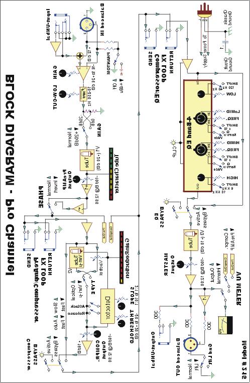
5 GROUNDING...21 TUBE REPLACEMENT...21 WE RE ON-LINE!...22 WARRANTY AND SERVICE INFORMATION...22 LIMITED WARRANTY...22 SERVICE...22 BLOCK DIAGRAM...24 A R T PRO CHANNEL SPECIFICATIONS
6 Features The Pro Channel is a unique product. It contains three independent, award-winning circuit designs: one of the finest tube microphone preamplifiers available, one of the finest optical tube compressors available, and one of the most flexible EQs you ve ever used. Developed in partnership with studio and live sound engineers, the Pro Channel possesses a sound that is not available from any other product on the market at any price! The Pro Channel was designed and constructed with the best components, assuring a lifetime of quiet, reliable performance. The Pro Channel offers the following: The award winning A R T SOUND! Very low-noise, tube-based mic/line preamplification with discreet, Class-A solidstate input circuitry Both electro-optical and variable-mu compressor designs Tube-based, semi-parametric, four-band equalization with selectable frequency ranges and Q Three hand-selected tubes VCA-less compressor circuitry (i.e., transparent dynamics control) Unique tube character and gain reduction LED metering Large 3 analog VU metering to monitor Output and Send points Bypassable compression and equalization circuitry XLR balanced inputs and outputs ¼ TS unbalanced inputs and outputs A rugged steel and aluminum chassis ¼ unbalanced insert points between the preamp and compressor and between the compressor and equalizer +48V phantom power Phase reversal Detented rotary controls Variable threshold and compression ratios Selectable attack and release time settings >90dB of dynamic range An internal power supply A five year warranty Design and manufacturing in the USA - 5 -
7 Overview Why use an external processing channel? The best way to get a signal to tape is by using the shortest signal path. In most cases, the shortest path is as follows: mic to preamp to compressor to EQ to tape deck. (The signal doesn t even go through a mixer!) This isn t a new concept, but it has become more relevant with the availability of affordable mixing consoles. As their name implies, most affordable mixers are optimized for signal routing and general level mixing. However, they are not necessarily your best option for the actual recording of tracks. The simple truth is that the Pro Channel has a better sounding and more flexible collection of circuits. Mixer manufacturers need to make tradeoffs between price and performance. Imagine the price of your mixer if each channel s EQ cost over $200 (we re not talking to those of you who have a $250,000+ console)! For those of us on a budget, it just doesn t make sense to spend a ton of money on a Cadillac console when a budget mixer and a few pieces of external gear is more cost effective. Even those engineers who regularly work on big consoles use external EQs, compressors, and preamps! The goal of any recording is to get the sounds right before you commit them to tape. The Pro Channel helps you get it right so you don t have to fix it in the mix. Design Notes The Pro Channel is a multi-purpose tool for audio engineering and recording. Enclosed in a two rack space (2U) chassis are three independent circuits featuring a tube-based analog preamplifier, a VCA-less compressor (selectable between optical or variable-mu control elements), and a semi-parametric, tube-based equalizer. The Pro Channel is designed to work seamlessly with any recording, soundreinforcement, or electronic instrument setup. A R T s Pro Channel circuitry is a hybrid design utilizing the most advanced solid-state and tube technology. With a transformerless power supply, the Pro Channel maintains exceptional signal integrity and extremely low noise. Signal flow within the Pro Channel is from the preamp, to the compressor, to the equalizer (although you can change the order of the circuits by utilizing the insert points). While the preamp is always active, the compressor and equalizer may be individually bypassed. The preamplifier s active, balanced, solid-state input provides extremely low noise and excellent CMRR (Common Mode Rejection Ratio). The ¼ input has a high impedance, which prevents the loading of any device connected to it and makes the Pro Channel perfect for DI or line level applications. The preamplifier s second stage 12AX7a tube runs on a regulated DC voltage, providing an additional 20dB of gain. Our design enables the tube to overload before the input or output stage, allowing you to manipulate the tube gain to meet different sonic criteria
8 The compression circuit features a VCA-less design and utilizes either optical (Vactrol ) or variable-mu, dual triode electronics for superior musical performance. The compressor is soft knee by design. Although it is capable of providing a thoroughly squashed signal, it was designed to excel in areas where transparent and musical dynamics control is desired. The beauty of the optical design is its ability to apply heavy amounts of compression without pumping and breathing like VCA-based compressors. The variable-mu compressor is capable of smoothly compressing fast-rising signal sources without undue side effects. In most cases you will hear the results of the compression without hearing the compressor. The tube-based equalizer was designed to help fix the instruments that give us headaches when recording (i.e., kick, snare, bass, toms, guitar amps, voice, etc.). The two sweepable parametric bands and selectable shelving bands have been optimized for musical instruments. The two sweepable bands overlap each other as well as the high and low shelving bands, providing you with the ultimate in flexibility. This EQ design gives you all the control you need to effectively dial in great sounds from even the poorest of sources. Setting Up Unpacking Your Pro Channel was packed with care at the factory. The shipping carton was designed to protect the unit during initial shipment. Please retain this carton for use in transporting the Pro Channel, or in the unlikely event that you need to return your unit for servicing. AC Power Hookup The Pro Channel has an internal power supply designed to operate at 100 to 125VAC, 50 to 60Hz. Units manufactured for use outside of the United States have been modified to comply with the required electrical specifications. Under no circumstances should the power cable be altered. If the cable becomes cut or damaged, discontinue use and have it replaced before operating. Audio Connections Audio connections to and from the Pro Channel are balanced XLR (Pin 2 = Hot (+), Pin 3 = Cold (-), Pin 1 = Ground) and unbalanced ¼ (Tip = Hot (+), Sleeve = Ground). The insert points between the preamp and compressor and the compressor and equalizer are unbalanced ¼ (Tip = Hot (+), Sleeve = Ground) connectors. We recommend using only high-quality cables and connectors
9 Installation The Pro Channel may be employed in a number of setups, including: between a microphone and a digital recorder, mixer, or analog recorder; in a mixer s channel insert points; between a microphone and signal processors; and between electronic musical instruments (synthesizers, guitars, basses, samplers, acoustic instruments with pickups, etc.) and other gear. Safety Precautions WARNING: To avoid the risk of shock or fire, do not expose this unit to moisture. Do not remove metal panels or chassis parts. Removing any chassis parts exposes dangerous high voltages. There are no user-serviceable parts inside. Refer all servicing to qualified personnel. If your power cord becomes damaged, always replace it with the same type as originally equipped. Since the cord is detachable, it is possible to replace it with a cord configured for the wrong voltage. Always refer to the unit s rear panel to determine the correct supply voltage, and then choose an appropriate cord. Powering Up When the power switch is turned on, the VU meter illuminates. It is important to remember to turn the Pro Channel on before any monitoring levels or power amps are turned on. The Pro Channel has the ability to add over 80dB of gain to its input signal and can cause the unit to produce a thump on power up and power down. Like all tube-based equipment, the Pro Channel needs to warm up before being used. Allow one to two minutes for the tubes to reach their proper operating temperature. If the Pro Channel fails to power up when the power switch is turned on, check to see that its power cord is plugged into an active outlet. If the unit still fails to operate properly, turn it off and unplug it, and then consult your dealer or A R T s Customer Service department
 refer to the Gain Switch (see next section) in the Norm position with the input routed to the ¼ unbalanced input jack.")
10 Front Panel Controls and Indicators Preamp Circuit Gain Control The Gain control sets the Pro Channel s input gain. Turn the control clockwise to increase gain and counter-clockwise to decrease it. The front panel calibrations (-11dB to +30 db) refer to the Gain Switch (see next section) in the Norm position with the input routed to the ¼ unbalanced input jack. Using the XLR (balanced) input connection results in 12dB more gain, thus making the control range from +1dB to +42dB. When setting the Gain control, refer to the first 10 segment Tube Character Array (directly under the VU meter) for a visual reference to the Pro Channel s internal signal levels. Hint: The Pro Channel s sweet spot is when all four of the yellow warm LEDs in the Tube Character meter are lit and the first red clip LED flashes occasionally. Gain Switch Use the Gain switch to add 20 db of gain to the Gain control s range (described above). With the switch in, the gain range is +9 to +50dB using the unbalanced input (or +21 to +62dB using the balanced input). Note: With most microphone applications, you ll find it necessary to use the Pro Channel with the +20dB gain switch in. (Use the setting that best fits your application.) Phantom Switch The Pro Channel can power any microphone needing +48 volts DC phantom power. Consult your microphone s documentation to see if phantom power is required. Turning the Phantom switch on supplies power to pins 2 and 3 of the balanced XLR input jack. Note: Be sure to turn down or mute the output of the Pro Channel when turning - 9 -
11 phantom power on or off. Allow seconds for the power to completely dissipate before disconnecting microphones. Another Note: Most dynamic microphones won t be affected or damaged if they are plugged into the Pro Channel when phantom power is turned on (we haven t run across any). However, if the mic doesn t need it, don t use it. Some things are best left untested! Phase Switch The Phase switch is used to reverse the phase of the signal leaving the Pro Channel s preamp section. The Phase switch reverses the polarity of the Preamp Output jack and everything after it in the signal chain. In the Normal position (out), the signal is inphase. In the Reverse position (in), the polarity of Pins 2 and 3 of the Output XLR jack (and the Tip of the ¼ jacks) are reversed and the signal is changed to 180 degrees out of phase with the input signal. In multiple microphone applications, mic placement can affect the phase of a signal. If two microphones pick up the same signal from different locations, the result can be a hollow or frequency-shifted sound; in some cases it may sound as if an instrument disappears completely. Depressing the Phase switch can remedy this problem. Note: In single microphone applications, switching the phase will produce no audible change in the output signal. Tube Drive/Gain Reduction Display The top LED display (directly under the VU meter) shows how the tube gain is affecting the input signal. These LEDs are calibrated with the tube circuitry to give you an accurate representation of the tube s output signal. The Tube Character LEDs measure the signal level before the Preamp Output level control use them as a visual guide for setting the Gain control. The first four (green) LEDs are labeled Cln. The tube is producing a clean output when these are lit. The next four (yellow) LEDs are labeled Warm. This is the optimal operating range for the Pro Channel s preamp. At this level, the tube is producing an output signal that most would term warm (or whatever you d like to call it simmering, toasty, etc.) You ll find the output signal has an enhanced bottom to low mid quality with smooth high frequency detail. The last two (red) LEDs are labeled Clip. The first red LED will light approximately 6dB before audible distortion occurs. If this light flickers, don t panic. The unique design of the Pro Channel allows the tube to distort well before any other gain stage. When a tube goes into distortion, it s a gradual process and tends to sound pleasing for a range before it turns into a distortion box. You may also find that a clipped level is suitable for some applications. Preamp Output Control The Preamp Output control sets the output level of the preamp section. In most situations you ll set this control around 12 o clock (or its 0 setting). The Preamp

12 Output control has a range of no output (from its fully counter-clockwise position), to +10dB of gain (when turned fully clockwise). When setting up the preamp, start with the Preamp Output at its 0 position. Once you get the Gain control set the way you want it to sound, use the Preamp Output control to set the level out of the preamp (much like using the master volume control on a guitar amplifier). Use the Preamp Output control to recover gain when you have the Gain control set low for a clean sound. Likewise, you can use the Preamp Output control to decrease the level out of the preamp when you re cranking the Gain control up for maximum tube warmth. Don t be afraid to set the Preamp Output control very high if you desire a very clean signal, but with a good deal of compression. (See the next section.) Compressor Circuit Threshold Control The Threshold control sets the point at which the compressor acts on the input signal. Turning this control counterclockwise lowers the Threshold, adding more compression to a signal. Turning this control clockwise raises the threshold. The Threshold control is dependent on the Preamp Output control (or the output of a device plugged into the Comp In insert point). The easiest way to set this control is to start with it fully clockwise. After setting the Preamp Output level, slowly turn the Threshold control counter-clockwise, (lowering the threshold) until you see the yellow (0dB) Threshold LED light in the Gain Reduction display (below the Tube Character array). Now adjust Threshold (either lower or higher) until you have the desired amount of compression. (Use the Gain Reduction LEDs as a visual guide) Ratio Control The Ratio control sets the compression ratio (or slope) for the compressor circuit. At its minimum position, the compression ratio is an active 2:1, meaning that for every 2dB over the threshold the input signal rises, the compressor s output will change by 1dB. This compression ratio is very mild and musical, and is ideal for smoothing all types of signals. At its maximum position, the compression ratio is greater than 10:1. This setting is typically called hard limiting as it allows only a 1dB change in level for any signal reaching 10dB above the set threshold. Hard limiting is ideal for applications where it is not desirable to exceed a certain level (i.e., mixing, popping bass, digital recording, etc.)
13 Attack Switch The Attack switch selects the attack characteristics of both the variable-mu and optical compressor circuits. The Fast position (in) allows the compressor to react quickly to fast-rising attacks. Note that the variable-mu circuit has an inherently fast response and can be aggressive on signals with quick transients, such as snare drums. The Slow position (out) can be helpful in reducing compression artifacts for signals with very little high frequency content, such as piano or flute. Release Switch The Release switch selects the release characteristics of the compressor circuit. The Fast position (in) allows the compressor to recover quickly once the signal falls below the threshold. The Auto position (out) allows the compressor to adjust itself depending on the characteristics of the input signal. Use the Fast setting when the signal has repetitive, consistent characteristics, such as on kick drums, snares, and vocals. Use the Auto setting when the signal has varying characteristics, such as long decaying notes alternating with quick notes and mix material. Type Switch This switch covers one of the more unique features of the Pro Channel. In the Optical position (out), the Pro Channel s compressor employs A R T s award-winning Vactrol -based compression element from the Pro VLA. Switching to the in position engages the dual-triode, variable-mu control element. This circuit is capable of considerably faster attack and release times than its optical counterpart. Experiment with the two types of compression to become familiar with how they react to different source material. Comp Bypass Switch A Bypass switch is included on the compressor circuit to enable you to remove it from the signal chain. In its Norm position (out), the compressor is active. When set to its Bypass position (in), signal passes from the preamp circuitry to the equalizer without compression and the adjacent red LED lights. Also, the Gain Reduction LED array operates as usual, though at a much dimmer level, to remind you that the compressor is out of the signal path. Use the Comp Bypass switch to achieve unity gain at the output of the Compressor. Unity gain is achieved when the compressor s active level is the same as its bypassed level. Toggle the switch between Norm and Bypass while adjusting the Compressor Output level. Once the levels are the same (use your ears and the VU Output Level meter), you ve reached the compressor s unity setting. Compressor Output Control The Compressor Output control sets the output level from the compressor circuit. Typically, a compressor s Output control is used to add gain to compensate for the amount lost due to compression. When the control is fully counter-clockwise, the output is off. Turning the control

14 clockwise increases the level to a maximum of +20dB of gain. While you can use the compressor to add gain to a signal, it is better to add gain before the compressor for the best signal to noise ratio. If you want to use the compressor to add more gain, use the VU meter to monitor the Pro Channel s output level, or use the meter on your recorder or mixer to make sure you won t clip the next piece of equipment in the chain. Clip Indicator The red Clip LED, located between the compressor and EQ sections, monitors the EQ s level at several internal points. It will illuminate 6dB before the available headroom is exceeded. When the Clip indicator lights, the level into the equalizer is too high; turn down either the Preamp Output control, the Compressor Output control, or the output level of the device plugged into the Comp In insert point. Equalizer Circuit The equalizer circuit in the Pro Channel is a tubebased, semi-parametric, four-band equalizer. All of the bands overlap, giving you the ultimate in flexibility. The normal bandwidth of each filter is purposely wide to provide a very musical sound. Low Control The Low control adjusts a shelving filter with a selectable corner frequency of either 40Hz or 120Hz. The two frequencies are selected with the Low switch (see below). The low shelving filter affects all frequencies below the corner frequency when applying boost or cut. In other words, cutting at 40Hz also cuts 30Hz, 20Hz, etc. The Low control has as range of ±12dB. Low Switch The Low switch selects the corner frequency of the Low control. In the out position, the corner is at 40Hz. In the in position, the corner is at 120Hz. 40Hz is great for enhancing sub-low frequencies such as those in bass guitars and kick drums. Cutting 40Hz can also help to clean up mixes that sound muddy or loose in the low end. 120Hz is generally the low-end for vocals, guitars and toms. Boosting 120Hz can add
15 weight or beef to a week vocal and cutting it can thin out a signal that takes up too much room in the low end. Lo-Mid Control The Lo-Mid control is a dual concentric pot (i.e., there are two controls one outer and one inner). The outer control is used to select a frequency while the inner one is used to apply boost or cut. The amount of boost or cut available depends on the setting of the Lo-Mid (Wide/Narrow) switch: ±12dB for Wide and ±20dB for Narrow. Bandwidths are approximately 1 octave and 1/3 octave, respectively. Also, the Lo-Mid control can cover two frequency ranges depending on the position of the Lo-Mid (X 10/Norm) switch; these ranges are 20Hz to 200Hz and 200Hz to 2KHz. Lo-Mid (X10/Norm) Switch The first Lo-Mid switch determines the frequency range covered by the Lo-Mid control (above). In its out position, the range is set at 20Hz to 200Hz. In its in position, the range is set at 200Hz to 2KHz. You ll notice that the Low and Lo-Mid control ranges overlap (meaning they cover the same frequencies); this is intentional and is one of the powerful features of the equalizer. Lo-Mid (Narrow/Wide) Switch The second Lo-Mid switch determines the width of the frequency band that the Lo-Mid control covers. In its Wide position (out), the Q is approximately 1.1. In its Narrow position (in), the Q is approximately 3.3. In general, you ll find that the Wide setting yields the most musical, unobtrusive results. Conversely, Narrow is preferable for surgical cutting of a frequency band without affecting adjacent frequencies too much. Hi-Mid Control Like the Lo-Mid control, the Hi-Mid control is a dual concentric pot. The outer control is used to select a frequency while the inner control is used to apply boost or cut. The Hi-Mid control can cover two frequency ranges, depending on the position of the Hi- Mid (X 10/Norm) switch; these ranges are 200Hz to 2KHz and 2KHz to 20KHz. Hi-Mid (X 10/Norm) Switch The first Hi-Mid switch determines the frequency range covered by the Hi-Mid control (above). In its out position, the range is set at 200Hz to 2KHz. In its in position, the range is set at 2KHz to 20KHz. Note: The Lo-Mid and Hi-Mid Frequency controls overlap in the 200Hz to 2KHz range. This feature allows either or both controls to be used in this range and is extremely useful if, for example, you want to cut at 200Hz and boost at 350Hz. Hi-Mid (Narrow/Wide) Switch The second Hi-Mid switch determines the width of the frequency band that the Lo-Mid control covers. In its Wide position (out), the Q is approximately 1.1. In its Narrow position (in), the Q is approximately 3.3. In general, you ll find that the Wide setting yields the most musical, unobtrusive results. Conversely, Narrow is preferable for
16 surgical cutting of a frequency band without affecting adjacent frequencies too much. High Control The High control adjusts a shelving filter with a selectable corner frequency of either 6KHz or 18KHz. The two frequencies are selected with the High switch (see below). The high shelving filter affects all frequencies above the corner frequency when applying boost or cut. In other words, cutting at 6KHz also cuts 7KHz, 8KHz, etc. The High Frequency control has as range of ±12dB. High Switch The High switch selects the corner frequency of the High control. In the out position, the corner is 18KHz. In the in position, the corner is 6KHz. 6KHz is great for adding top end to guitars, snare drums and vocals. Cutting 6KHz can also help to take the edge off brittle or harsh sounding instruments. 18KHz may be used to add sizzle to cymbals and is generally referred to as the air band. While there aren t many instruments that contain 18KHz information directly, many instruments and mixes contain upper harmonics that can add extra definition and space when boosted. Cutting at 18KHz can decrease hiss and noise. Note: The High and Hi-Mid controls intentionally overlap to give you greater flexibility. For example, on cymbals try boosting 18KHz with the High control while cutting 20KHz with the Hi-Mid control for a bright, yet noise-free result. EQ Byp Switch A Bypass switch is included in the equalizer circuit to enable you to remove it from the signal chain. When set to its Bypass position (in), signal passes from the compressor circuitry to the output tube section with no equalization. The red LED lights when Bypass is engaged. In its Norm position (out), the equalizer is active. Use the EQ Bypass switch to compare your equalized and unequalized sound a reality check to make sure you are making an improvement! It may be necessary to adjust the Master Output control to balance the apparent level of the EQ d and un-eq d signal

17 Master Controls Master Output Control The Master Output control sets the final output level leaving the Pro Channel. When the control is fully counterclockwise, there is no output. Turning the control clockwise increases the output level to a maximum gain of +10dB. When setting this control, refer to the VU Meter (set for the Output option see below) or the level meter on your recorder or mixer. VU Meter A backlit, average reading VU meter can accurately monitor levels at several points in the Pro Channel. The 0VU level is calibrated to +4dBu at any of the internal points and at the ¼ Output connector. For the same calibration on the XLR output, a 600Ω load must be used otherwise the balanced output is 6dB higher (0VU = +10dBu). Note: When running the Pro Channel into a mixing console or recorder, always reference the meter on the mixer or recorder when setting output levels. Not all meters are calibrated the same and it is always best to look at the level entering the last piece of equipment in the chain. VU Meter Switches The VU Meter switches determine which point feeds the VU meter. The right-hand switch selects either the Pro Channel s output or an internal point selected by the other switch. The left-hand switch selects either the preamp output or the compressor output. Note: When the right-hand switch is set to Output, the left-hand switch has no effect. Another Note: The internal level-monitoring points also correspond to the level at the Send jacks of the two insert loops. If you are using either of these jacks as your output to other devices, switch the VU Meter to monitor the appropriate point. Power The Power switch supplies and removes power from the Pro Channel. The Pro Channel should be turned on only after all monitor levels are turned down or off, to protect against any thumping caused by high gain settings. Likewise, the Pro Channel should be turned off after turning all monitor levels down. The Output Level VU meter is illuminated when power is on
, and Pin 3 = Cold (-).")
18 Title: (259rp.eps) Creator: Adobe Preview: This with Comment: a EPS preview Illustrator(TM) picture included was not in 7.0 This PostScript other EPS types picture printer, of printers. will but not to it. saved ato Rear Panel Connections Input and Output Connections The Pro Channel s XLR connectors follow the AES standard: Pin 1 = Ground, Pin 2 = Hot (+), and Pin 3 = Cold (-). The unbalanced ¼ phone jacks are the typical Tip = Hot (+) and Sleeve = Ground. Note: None of the Pro Channel s circuitry is connected directly to the metal chassis. Either the input or output ground must be connected to another portion of the signal path in order to establish a ground reference. Input Only one Input jack should be used at a time. However, both inputs can be hard-wired without having to disconnect one while using the other (i.e., if no load is placed on the XLR input, the ¼ jack will function as if there was nothing connected to the XLR input). However, it is still preferable to disconnect any unused cables to avoid pick up of extraneous noise, hum, or RF interference. Output Both the balanced and unbalanced Output connections may be used simultaneously. This feature is particularly handy when using the Pro Channel as a direct box for instruments or line level signals. XLR GND Switch If you hear a hum when using the Pro Channel s XLR output, a ground loop may be the problem. To remedy this problem, press the XLR GND switch in, to its Lift position, to disconnect the ground wire (pin 1) from the XLR output. This action interrupts the ground path and therefore breaks the loop. Loop Inserts Two signal loops are provided for the following applications: to connect external equipment to the Pro Channel, to use only specific individual circuits, or to take direct signal paths from specific sections. The connections are unbalanced ¼ (Tip = Hot (+), Sleeve = Ground). Both of the Send jacks may be used without interrupting signal-flow through the Pro Channel. The Return jacks break the signal-flow when a jack is inserted
19 The loops may also be utilized to re-patch the compressor and equalizer circuits in a different order (i.e., signal flow = preamp to equalizer to compressor). For information on how to do this, see Loop Connection Examples, below. Preamp - Compressor Loop A loop is provided between the preamp s output and the compressor s input. The Preamp Out (Send) jack takes its signal after the Preamp Output control. This jack may be used to send an unbalanced signal directly to an input of a recorder, mixer, or other piece of outboard equipment. The Comp In (Return) jack places its signal before the compressor s Threshold control. This jack may be used to connect the output of a piece of equipment to the input of the Pro Channel s compressor circuit. Since there is no Compressor Input Level control, equipment patched into the insert loop should have an Output control for setting proper levels. Compressor - EQ Loop A loop is provided between the compressor s output and the equalizer s input. The Comp Out (Send) jack takes its signal after the Compressor Output control. This jack may be used to send an unbalanced signal directly to an input of a recorder, mixer or other piece of outboard equipment. The EQ IN (Return) jack may be used to connect the output of a piece of equipment to the input of the Pro Channel s equalizer circuit. Since there is no Equalizer Input Level control, equipment patched into the insert loop should have an Output control for setting proper levels. Loop Connection Examples To use only the Pro Channel s preamp: Plug a mic, instrument, or line level signal into one of the Input jacks. Either connect the Preamp Out (Send) jack into the input of the next piece of gear, or bypass the compressor and equalizer circuits and connect either of the Output jacks to the input of the next piece of equipment. To use only the Pro Channel s compressor: Plug a line level signal (such as a mixer s Send) into the Comp In (Return) jack. Connect the Comp Out (Send) jack to the input of the next piece of equipment, such as a mixer s Return. To use only the Pro Channel s equalizer: Plug a line level signal into the EQ In (Return) jack. Connect either of the Pro Channel s Outputs to the input of the next piece of equipment. To place the equalizer before the compressor: Plug a mic, instrument, or line level signal into one of the Input jacks. Connect Preamp Out (Send) to EQ In (Return). Connect the unbalanced Output to Comp In (Return). Use Comp Out (Send) as the main output to the input of the next piece of equipment. Don t forget that it is possible to use each section of the Pro Channel on a separate track. For example, the bass track can run through the compressor, the vocal track through the preamp, and the guitar track through the EQ all at the same time!

20 Applications The Pro Channel s main application is as a processing channel for a microphone, instrument, or line level source. To use the Pro Channel as a mic or line preamplifier only, simply press the Bypass switches to bypass the compression and equalizer circuitry. Plug a microphone directly into either input and set the Input and Output controls to provide an appropriate level into the next stage of your system. The Pro Channel is ideal for use as a DI box. Plug your instrument into either Input and use the XLR, ¼, or both outputs to connect to your recorder, board, or PA system. Experiment with different input level settings for distinct textures. The Pro Channel has enough gain to be used in front of a power amplifier. To use the Pro Channel as an instrument preamp, simply plug the instrument into the Input jack and connect the Output jack to the power amplifier s Input. See Loop Connections for further hook-up options and for using the Pro Channel s individual sections. In most cases, the Pro Channel offers superior performance to your console s on-board preamp. To use the Pro Channel instead of your console s preamp, simply connect the Pro Channel s Output to the Line Input of your mixer s input channel. Note: You can connect the XLR Output jack of the Pro Channel to the XLR Input of your mixer, however most affordable mixers do not allow you to bypass their internal preamp when using the XLR jack. You will cause no harm to either unit when doing this, but you will probably experience slightly higher noise due to the fact that you are now preamplifying your mixer s preamp. Note: Be certain that you do not connect the Pro Channel s XLR Output to a mixer input that has Phantom Power applied. EQ Tips
21 What is the best way to use EQ? There are two schools of thought on EQ: 1) Use as much as you need to make things sound good. 2) Don t use any EQ. Most people follow the suggestion of if it sounds good, it is good. You need to use your ears and judge for yourself as their are no steadfast rules for EQ ing. Here are a few pointers to guide you: Always tweak the instrument you are EQ ing while listening to it in the mix. EQ ing an instrument when it is soloed doesn t give you a good representation of how it will sound when mixed with other instruments. You d be surprised at how bad a killer guitar track can sound when it is isolated from the rest of the mix. Remember, what makes it killer is how it sounds in relation to the other instruments! Keep the big picture in mind. Most people think of EQ as boosting only ( we ll just add a little EQ... ). Many times a bad sounding instrument can be fixed by simply isolating the offending frequency and pulling it out. After you determine approximately where the problem area is in the instrument (highs, lows, mids), isolate the track and boost one of the mid bands. Slowly sweep through its frequency range. When the really nasty sound jumps out at you (you ll know it when it happens) turn the boost back to 0 (12 o clock). Now put the track back into the mix and cut the frequency. You ll have to adjust the level of the instrument depending on how much you cut, but you should find that with the problem area pulled out, the instrument works better in the mix. When recording EQ d instruments, make sure you have a good representation of frequencies on tape. Always monitor off-tape when recording to ensure that what you re hearing is what is on tape. When recording things like kick drums, make sure you have enough low end thud and high end click (if applicable) before you record. Recording guideline: You can always boost or cut frequencies after they ve been recorded, but you can t add frequencies that weren t recorded! Also, if you get the right sound when you record the tracks, you shouldn t be spending a lot of time re- EQ ing during the mix. When mixing, concentrate on blending tracks and the song s dynamics. If you find yourself EQ ing everything, take a break and come back to it later. Start mixing with a group of instruments such as the whole drum kit or guitars and bass, instead of listening to individual tracks. Mixing is the time for tweaking not applying a sonic re-design. Once again, if it sounds good, print it! Trust your ears never mind where the knobs are pointing
22 Special Effects For industrial, metal, or just flavor textures, experiment with the Pro Channel. Overdriving the preamp, compressor, and equalizer circuitry can add interesting textures when blended with vocals and other instruments. Purposely placing signals out of phase can also yield interesting results. No harm will come to the Pro Channel with this type of experimentation. However, be sure to have output and monitoring levels turned DOWN before testing the sound. Remember, you have a great amount of gain available in the Pro Channel! Grounding Avoiding ground loops while several pieces of equipment are connected is one of the most common challenges in recording. For this reason, all ART recording gear does not have a direct connection between the audio circuit ground and the chassis ground. This technique enables the gear to be safely grounded through the 3-prong AC cord and also to the previous and next items in the signal chain with optimum noise performance. At least one ground connection must be made between the Pro Channel and the rest of the signal chain. If you hear hum when using the Pro Channel s XLR output, try pressing the XLR GND switch in, to its Lift position, to disconnect the ground wire (pin 1) from the XLR output. Tube Replacement The Tubes in your Pro Channel should last for many years. They are hand-sorted for optimal performance in our specific circuits. In the event that you need to replace them, A R T suggests that you do so with tubes available from A R T. These are matched to the Pro Channel and will yield consistent sonic results. You can replace the tubes with other brands, however A R T has no responsibility for the resulting sound quality; they may sound better, they may sound worse. The choice is yours. Unauthorized alterations to the Pro Channel also will result in voiding the warranty. A R T retains a policy of constant product improvement. A R T reserves the right to make changes in design or make additions to or improvements upon this product without any obligation, and to install the same on products previously manufactured. In other words, specifications are subject to change without notice. Applied Research and Technology, Inc. (716) (Phone) 215 Tremont Street (716) (FAX) Rochester, NY USA
23 We re on-line! For Product information, questions, applications, tips, answers and general discussion with A R T employees, look for A R T on the Internet. us at art@artroch.com and check out our Web Site at Warranty and Service Information Limited Warranty Applied Research and Technology, Inc. (A R T) will provide warranty service for this unit in accordance with the following warranty statement. A R T warrants to the original purchaser that this product is free from defects in workmanship and materials for a period of three years from the date of purchase. A R T will, without charge, repair or replace, at its option, defective product or component parts upon prepaid delivery to the factory service department or an authorized service center, accompanied by proof of purchase date in the form of a valid sales receipt. EXCLUSIONS: This warranty does not apply in the event of misuse or abuse of the product or as a result of unauthorized alterations or repairs. This warranty is void if the serial number is altered, defaced, or removed. A R T reserves the right to make changes in design and make additions or improvements upon this product without any obligation to install the same on products previously manufactured. A R T should not be liable for any consequential damages, including without limitation to damages resulting from the loss of use. Some states do not allow limitation of incidental or consequential damages, so the above limitation or exclusion may not apply to you. This warranty gives you specific rights and you may also have other rights which vary from state to state. For products purchased outside the United States, an authorized distributor of Applied Research and Technology, Inc. will provide service. Service The following information is provided in the unlikely event that your unit requires service. Use this procedure to return units from within the United States only. For service outside the United States, please contact your authorized A R T distributor. 1) Be sure the unit is the cause of the problem. Check to make sure the unit has power supplied, all cables are connected correctly, and the cables themselves are in working condition. 2) If you find the unit to be at fault, write down a description of the problem, including how and when the problem occurs. 3) Call the factory for a Return Authorization (RA) number
24 4) Pack the unit in its original carton or a reasonable substitute. The packing box is not recommended for a shipping carton. Put the packaged unit in another box for shipping. Print the RA number clearly under the address. 5) With your unit, include a return shipping address (we cannot ship to a P.O. Box), a copy of your purchase receipt, a daytime phone number, and the description of the problem. 6) Ship the unit to the following address: Applied Research and Technology, Inc. 215 Tremont Street Rochester, NY Attn: Repair Department R.A.# 7) Contact our Customer Service department at (716) for your Return Authorization number or questions regarding your repair. Customer Service hours are Monday through Friday, 9:00AM to 5:00PM Eastern Time
25 - 24 -
26 A R T Pro Channel Specifications Dimensions 6.5"D x 19"W x 3.50"H Weight 12.0 lbs. Maximum Gain XLR to XLR: 83dB, ¼ to ¼ : 65dB Dynamic Range >100dB (20-20KHz) Frequency Response 20Hz to 20KHz (±0.5dB) Low-Cut Filter Single-Pole Variable: -3dB@10Hz to 250Hz Input/Output Connections XLR balanced and ¼ unbalanced Insert Connections ¼ unbalanced Input Impedance 1.67KΩ (XLR), 1MΩ (¼ ), 10KΩ+ ( ¼ inserts) Output Impedance 600Ω (XLR), 300Ω (all ¼ ) Maximum Input Level +15dBu (XLR), +21dBu (¼ ) Maximum Output Level +27dBu (XLR), +22dBu (¼ ) Equivalent Input Noise -130dBu (XLR to XLR, A wtd) Phantom Power +48V DC (switchable) Compression Ratio Variable: 2:1 to >10:1 Attack Time Fast: 2ms (optical), 0.5ms (vari-mu) Slow: 15ms (for 20dB of comp) Release Time Fast: 300ms Auto: 100ms-3sec (program dependent) Maximum Compression 30dB (optical), 23dB (vari-mu) EQ Frequency Bands Low Shelf 40Hz, 120Hz Low-Mid Sweepable 20Hz to 200Hz, 200Hz to 2KHz (Shift out / in) Low-Mid Q Wide, Narrow (Q=1.1 / 3.3) High-Mid Sweepable 200Hz - 2KHz, 2KHz - 20KHz (Shift out / in) High-Mid Q Wide, Narrow (Q=1.1 / 3.3) High Shelf 6KHz, 18KHz Boost/Cut per Band Low, High: ±12dB Lo-Mid and Hi-Mid: ±12dB (wide), ±20dB (narrow) Total Harmonic Distortion (THD) <0.1% (typical) Tubes Three (Hand-Selected) Power Requirements VAC, 30W (Export units configured for country of destination) The Pro Channel was designed and manufactured in the United States of America. This manual was written by Jeff Cary, Dan Pierce, and David Shaw Applied Research and Technology, Inc
PRO VLA PROFESSIONAL TWO CHANNEL VACTROL/TUBE LEVELING AMPLIFIER
 PRO VLA PROFESSIONAL TWO CHANNEL VACTROL/TUBE LEVELING AMPLIFIER USER S GUIDE TABLE OF CONTENTS Introduction 2 Registration 2 Features 3 Overview 4 Setting Up 5 Unpacking 5 AC Power Hookup 5 Audio Connections
Tube MP/C. User s Manual
 Tube MP/C User s Manual IMPORTANT SAFETY INSTRUCTIONS READ FIRST This symbol, wherever it appears, alerts you to the presence of uninsulated dangerous voltage inside the enclosure. Voltage that may be
T L Audio. User Manual C1 VALVE COMPRESSOR. Tony Larking Professional Sales Limited, Letchworth, England.
 T L Audio User Manual C1 VALVE COMPRESSOR Tony Larking Professional Sales Limited, Letchworth, England. Tel: 01462 490600. International +44 1462 490600. Fax: 01462 490700. International +44 1462 490700.
PRO MPA. Professional Two Channel Tube Microphone Preamplifier
 PRO MPA Professional Two Channel Tube Microphone Preamplifier USER S GUIDE TABLE OF CONTENTS Introduction 2 Registration 2 Features 3 Overview 4 Setting Up 4 Unpacking 4 AC Power Hookup 4 Audio Connections
Pro VLA II PROFESSIONAL TWO CHANNEL VACTROL /TUBE LEVELING AMPLIFIER USER S GUIDE
 Pro VLA II PROFESSIONAL TWO CHANNEL VACTROL /TUBE LEVELING AMPLIFIER USER S GUIDE IMPORTANT SAFETY INSTRUCTIONS READ FIRST This symbol, wherever it appears, alerts you to the presence of uninsulated dangerous
HeadAmp 4 Pro. User s Manual. Project Series. Five Channel Headphone Amp with Listen and Talkback
 HeadAmp 4 Pro Five Channel Headphone Amp with Listen and Talkback Project Series User s Manual IMPORTANT SAFETY INSTRUCTIONS READ FIRST This symbol, wherever it appears, alerts you to the presence of
IMPORTANT SAFETY INSTRUCTION READ FIRST
 IMPORTANT SAFETY INSTRUCTION READ FIRST This symbol, whenever it appears, This symbol, wherever it appears, alerts alerts you to the presence of uninsulated you to important operating and maintenance dangerous
PRO MPA II. ART PRO MPA II Microphone Preamplifier USER S GUIDE
 PRO MPA II ART PRO MPA II Microphone Preamplifier USER S GUIDE IMPORTANT SAFETY INSTRUCTIONS READ FIRST This symbol, wherever it appears, alerts you to the presence of uninsulated dangerous voltage inside
clipping; yellow LED lights when limiting action occurs. Input Section Features
 ELX-1A Rack-Mount Mic/Line Mixer Four inputs, one output in a single rack space Very-highery-high-quality audio performance High reliability Extensive filtering circuitry and shielding protect against
MX-206 Stereo Microphone Mixer. Operating Manual
 MX-206 Stereo Microphone Mixer Operating Manual ASHLY AUDIO INC. 847 Holt Road Webster, NY 14580-9103 Phone: (585) 872-0010 Toll-Free: (800) 828-6308 Fax: (585) 872-0739 www.ashly.com Operating Manual
IMPORTANT SAFETY INSTRUCTION READ FIRST
 IMPORTANT SAFETY INSTRUCTION READ FIRST This symbol, whenever it appears, This symbol, wherever it appears, alerts alerts you to the presence of uninsulated you to important operating and maintenance dangerous
Recording to Tape (Analogue or Digital)...10
...10") c o n t e n t s DUAL MIC-PRE Green Dual Mic Pre (introduction).............................4 Section (i): Setting Up Power Connections...........................................4 Power Supply................................................5
c o n t e n t s DUAL MIC-PRE Green Dual Mic Pre (introduction).............................4 Section (i): Setting Up Power Connections...........................................4 Power Supply................................................5
Summit Audio Model TLA-50 Tube Leveling Amplifier
 Summit Audio Model TLA-50 Tube Leveling Amplifier ATTACK FAST SLOW MEDIUM 3 4 5 6 7 TUBE LEVELER 40 60 80 100 VU 3 4 5 6 TLA-50 7 FAST SLOW RELEASE OUTPUT RED. METER 2 1 0 10 GAIN 9 8 7 5 3 1 0 1 2 +3
Passive Four Channel Stereo/Mono Mixer/Splitter. Artcessories. User's Manual
 Passive Four Channel Stereo/Mono Mixer/Splitter Artcessories User's Manual IMPORTANT SAFETY INSTRUCTION READ FIRST This symbol, whenever it appears, alerts you to the presence of uninsulated dangerous
FAT MAN FAT 1. TLAudio. user manual. stereo valve compressor. TL Audio Limited, Sonic Touch, Iceni Court, Icknield Way, Letchworth, SG6 1TN England
 user manual FAT MAN by TLAudio TL Audio Limited, Sonic Touch, Iceni Court, Icknield Way, Letchworth, SG6 1TN England Tel: +44 (0)1462 680888 Fax: +44 (0)1462 680999 email: info@tlaudio.co.uk web: http://www.tlaudio.co.uk
PHOENIX AUDIO. Owner s Manual
 PHOENIX AUDIO Costa Mesa CA 92262 USA Telephone +1 866 302 1091 Email :sales@phoenixaudio.net Owner s Manual Firstly, let us congratulate you on your purchase of the Ascent-Two Microphone Pre- Amplifier.
DMP3. Users Manuual. Ver. # DMP
 TM AUDIO DMP3 Users Manuual Ver. # DMP3-121701 Table of Contents Introduction.......................................................2 DMP3 Features....................................................2
MANUAL ENGLISH Core Club Ordercode: D2314
 MANUAL ENGLISH Core Club Ordercode: Highlite International B.V. Vestastraat 2 6468 EX Kerkrade the Netherlands Table of contents Warning... 2 Unpacking Instructions... 2 Safety Instructions... 2 Operating
560A 500 SERIES COMPRESSOR/LIMITER OWNER S MANUAL
 500 SERIES COMPRESSOR/LIMITER OWNER S MANUAL Warranty 1. Please register your product online at www.dbxpro.com. Proof-of-purchase is considered to be the responsibility of the consumer. A copy of the original
PROFESSIONAL 2 CHANNEL SOLID-STATE MIC / LINE PREAMPLIFIER USER S MANUAL
 PROFESSIONAL 2 CHANNEL SOLID-STATE MIC / LINE PREAMPLIFIER USER S MANUAL SAFETY INSTRUCTIONS This symbol, wherever it appears, alerts you to important operating and maintenance instructions in the accompanying
TUBE MIX FIVE CHANNEL MIXER WITH USB AND ASSIGNABLE 12AX7 TUBE. User's Manual
 TUBE MIX FIVE CHANNEL MIXER WITH USB AND ASSIGNABLE 12AX7 TUBE User's Manual IMPORTANT SAFETY INSTRUCTIONS READ FIRST This symbol, wherever it appears, alerts you to the presence of uninsulated dangerous
Pre1. Balanced Control Preamplifier. User's Guide and Operating Information
 Pre1 Balanced Control Preamplifier User's Guide and Operating Information Bel Canto Design 212 Third Avenue North Suite 345 Minneapolis, MN 55401 Phone: (612) 317.4550 Fax: (612) 359.9358 Email: Info@BelCantoDesign.com
Table of Contents. Introduction 2 C valve Features 3. Controls and Functions 4-5 Front Panel Layout 4 Rear Panel Layout 5
 Safety Instructions Table of Contents Introduction 2 C valve Features 3 Controls and Functions 4-5 Front Panel Layout 4 Rear Panel Layout 5 Operating the C valve 6-13 Setting Up the C valve 6-7 Setting
Overview. A 16 channel frame is shown.
 Overview A 16 channel frame is shown. 22 Mono Input Channel 1 - MIC INPUT The mic input accepts XLR-type connectors and is designed to suit a wide range of BALANCED or UNBALANCED signals. Professional
DP1 DYNAMIC PROCESSOR MODULE OPERATING INSTRUCTIONS
 DP1 DYNAMIC PROCESSOR MODULE OPERATING INSTRUCTIONS and trouble-shooting guide LECTROSONICS, INC. Rio Rancho, NM INTRODUCTION The DP1 Dynamic Processor Module provides complete dynamic control of signals
VACUUM TUBE COMPRESSOR
 1969 VACUUM TUBE COMPRESSOR OPERATORS MANUAL CONTENTS SAFETY CONSIDERATIONS page 1 INTRODUCTION page 2 APPLICATIONS page 2 INSTALLATION page 3 CONTROL DESCRIPTIONS: page 5 Compressor page 5 Microphone
USER MANUAL MX102 & MX1202
 USER MANUAL MX102 & MX1202 WWW.PULSE-AUDIO.CO.UK 1 SAVE THESE SAFETY INSTRUCTIONS Thank you for purchasing our product. To assure the optimum performance, please read this manual carefully and keep it
TL AUDIO M4 TUBE CONSOLE
 TL AUDIO M4 TUBE CONSOLE USER MANUAL TL AUDIO M4 TUBE CONSOLE M4 INTRODUCTION... 3 M4 MIXER TECHNICAL SPECIFICATION... 4 Mic Input:... 4 Line Input:... 4 Phase Rev:... 4 High Pass Filter:... 4 Frequency
DIGITAL SPEAKER MANAGEMENT UK
 DSM2-6mkII DIGITAL SPEAKER MANAGEMENT 170.659UK Features 96kHz sampling frequency, 32-bit A/D and D/A converter, 24-bit DSP processor Input channel: 6-band parametric EQ, Delay, Polarity Output channel:
500 SERIES DE-ESSER OWNER S MANUAL
 500 SERIES DE-ESSER OWNER S MANUAL Warranty 1. Please register your product online at www.dbxpro.com. Proof-of-purchase is considered to be the responsibility of the consumer. A copy of the original purchase
PL-2 Analog Peak Limiter Manual
 PL-2 Analog Peak Limiter Manual Features Two independent channels with stereo link JFET (hard) and MOSFET (soft) peak limiting modes Limiter circuit 'switched out' of the signal path when below threshold
SyncGen. User s Manual
 SyncGen User s Manual 1 IMPORTANT SAFETY INSTRUCTION READ FIRST This symbol, whenever it appears, alerts you to the presence of uninsulated dangerous voltage inside the enclosure-voltage that may be sufficient
Vintage Audio MSL-MK2. Quad VCA Buss Compressor
 Vintage Audio MSL-MK2 Quad VCA Buss Compressor Vintage Audio MSL-mk2 Quad VCA Compressor ++ Congratulations on your purchase of your new Vintage Audio MSL-mk2 Quad VCA Buss compressor. The MSL-mk2 is based
Heat: This product should be situated away from other heat sources such as fire, high heat emitting devices, heaters, etc.
 SAFETY INSTRUCTIONS CAUTION: To reduce the risk of electrical shock, do not remove the cover or rear panel of this unit. Do not expose this appliance to rain or moisture. No user serviceable parts inside.
Optical Compressor Owner s Manual Rev A all contents Grace Design/ Lunatec LLC
 Optical Compressor Owner s Manual Rev A all contents Grace Design/ Lunatec LLC info@gracedesign.com / www.gracedesign.com 2434 30th Street, Boulder, CO 80301 USA tel 303.443.7454 fax 303.444.4634 Welcome
CFX 12 (12X4X1) 8 mic/line channels, 2 stereo line channels. CFX 16 (16X4X1) 12 mic/line channels, 2 stereo line channels
 8 mic/line channels, 2 stereo line channels. CFX 16 (16X4X1) 12 mic/line channels, 2 stereo line channels") COMPACT CFX MIXERS COMPACT SOUND REINFORCEMENT MIXERS WITH EFX FOR THE GIGGING MUSICIAN THREE MODELS CFX 12 (12X4X1) 8 mic/line channels, 2 stereo line channels CFX 16 (16X4X1) 12 mic/line channels, 2
COMPACT CFX MIXERS COMPACT SOUND REINFORCEMENT MIXERS WITH EFX FOR THE GIGGING MUSICIAN THREE MODELS CFX 12 (12X4X1) 8 mic/line channels, 2 stereo line channels CFX 16 (16X4X1) 12 mic/line channels, 2
AG 500SC. Owners Manual. Manual Version 1.7
 AG 500SC Owners Manual Manual Version 1.7 1. Table of Contents I. Getting Started page 3. A. Safety Instructions B. Manual Conventions C. Basic Setup D. Protection Modes II. Features and Functions page
12 Channel Media Splitter MS12 Mk2 User manual
 12 Channel Media Splitter MS12 Mk2 User manual 01. 12 Channel Media Splitter MS12 Mk2 An audio distribution amplifier primarily designed to feed multiple ENG cameras from a single lectern microphone at
THERMIONIC CULTURE. TheEarlybird 2.2. valve microphone pre-amplifier OPERATING MANUAL
 THERMIONIC CULTURE TheEarlybird 2.2 valve microphone pre-amplifier OPERATING MANUAL WARNING For your personal safety, please read this operating manual and warning thoroughly before using the equipment.
3124mb+ All Discrete 4 Channel Mic/Instrument Preamplifier with Stereo Mixer Operator s Manual
 3124mb+ All Discrete 4 Channel Mic/Instrument Preamplifier with Stereo Mixer Operator s Manual Written by Carl J Houde 2015 Table of Contents 1.0 Introduction... 3 2.0 Overview... 4 2.1 3124mb+ Features
Element 78 MPE-200. by Summit Audio. Guide To Operations. for software version 1.23
 Element 78 MPE-200 by Summit Audio Guide To Operations for software version 1.23 TABLE OF CONTENTS IMPORTANT SAFETY AND GROUNDING INSTRUCTIONS COVER 1. UNPACKING AND CONNECTING...3 AUDIO CONNECTIONS...4
Chameleon Labs Model 7720
 Chameleon Labs Model 7720 Stereo Compressor Owner s Manual 704 228 th Avenue NE, # 826 Sammamish, WA 98074 206-264-7602 www.chameleonlabs.com Revision C - December, 2007 UNPACKING AND INSPECTION Carefully
CMX-DSP Compact Mixers
 CMX-DSP Compact Mixers CMX4-DSP, CMX8-DSP, CMX12-DSP Introduction Thank you for choosing a Pulse CMX-DSP series mixer. This product has been designed to offer reliable, high quality mixing for stage and/or
Tubeopto 8 8-CHANNEL TUBE MICROPHONE PREAMPLIFIER / OPTICAL INTERFACE USER S GUIDE
 Tubeopto 8 8-CHANNEL TUBE MICROPHONE PREAMPLIFIER / OPTICAL INTERFACE USER S GUIDE IMPORTANT SAFETY INSTRUCTIONS READ FIRST This symbol, wherever it appears, alerts you to the presence of uninsulated dangerous
PROJECT CHANNEL ESSENTIAL CHANNEL STRIP. Owner s Manual
 PROJECT CHANNEL ESSENTIAL CHANNEL STRIP Owner s Manual SAFETY DECLARATIONS TABLE OF CONTENTS CAUTION: For protection against electric shock, do not remove the cover. No user serviceable parts inside. WARNING:
Ashly Audio Inc. 847 Holt Road, Webster, NY Toll Free (800) , Telephone (585) , FAX (585)
 , Telephone (585) , FAX (585)") XR 1001 Electronic Crossover Operating Manual U U U U U U db Hz db Hz Ashly Audio Inc. 847 Holt Road, Webster, NY 14580-9103 Toll Free (800) 828-6308, Telephone (585) 872-0010, FAX (585) 872-0739 www.ashly.com
XR 1001 Electronic Crossover Operating Manual U U U U U U db Hz db Hz Ashly Audio Inc. 847 Holt Road, Webster, NY 14580-9103 Toll Free (800) 828-6308, Telephone (585) 872-0010, FAX (585) 872-0739 www.ashly.com
SM Pro Audio. Operating Manual - TB101/202. Version 1.0 Feb
 SM Pro Audio Operating Manual - TB101/202 Version 1.0 Feb 2004 www.smproaudio.com SAFETY INSTRUCTIONS CAUTION: To reduce the risk of electrical shock, do not remove the cover or rear panel of this unit.
User Guide and Reference Manual
 User Guide and Reference Manual i TABLE OF CONTENTS Important Safeguards i BBE Process Explained 1 Product Description 2 Applications 2 Front Panel Controls 3 Rear Panel Connections 4 Specifications 5
USB Phono Plus. Project Series USER S MANUAL. Audiophile Computer Interface
 USB Phono Plus Audiophile Computer Interface Project Series USER S MANUAL IMPORTANT SAFETY INSTRUCTION READ FIRST This symbol, whenever it appears, alerts you to the presence of uninsulated dangerous voltage
bel canto SEP2 Single Ended Triode Tube Preamplifier User's Guide and Operating Information
 bel canto SEP2 Single Ended Triode Tube Preamplifier User's Guide and Operating Information Bel Canto Design 212 Third Avenue North, Suite 274 Minneapolis, MN 55401 USA Phone: 612 317.4550 Fax: 612.359.9358
Table of Contents. Read This First.2. Introduction by Jim Fosgate...3. Unpacking..4. Tubes and Tube shield Installation 5. Product Placement...
 Owner s Manual Table of Contents Read This First.2 Introduction by Jim Fosgate...3 Unpacking..4 Tubes and Tube shield Installation 5 Product Placement...6 Connecting your Fosgate Signature..7 Phono stage
TDM 24CX-2 24CX-3 24CX-4 ELECTRONIC CROSSOVER OWNER S MANUAL A U D I O
 TDM A U D I O 24CX-2 24CX-3 24CX-4 ELECTRONIC CROSSOVER OWNER S MANUAL TDM AUDIO INC. 7270 BELLAIRE AVE. NORTH HOLLYWOOD, CA 91605 (818) 765-6200 TDMAUDIO.COM IMPORTANT! *** Read Before Using *** CAUTION:
CM4-BT. Compact Mixer with Bluetooth UK User Manual
 CM4-BT Compact Mixer with Bluetooth 170.804UK User Manual Caution: Please read this manual carefully before operating Damage caused by misuse is not covered by the warranty Introduction: Thank you for
LX20 OPERATORS MANUAL
 LX20 OPERATORS MANUAL CONTENTS SAFETY CONSIDERATIONS page 1 INSTALLATION page 2 INTRODUCTION page 2 FIRST TIME USER page 3 SYSTEM OPERATING LEVELS page 3 FRONT & REAR PANEL LAYOUT page 4 OPERATION page
OWNERS MANUAL LUNATEC V3 MICROPHONE PREAMPLIFIER AND A/D CONVERTER
 OWNERS MANUAL LUNATEC V3 MICROPHONE PREAMPLIFIER AND A/D CONVERTER LUNATEC 35 +48 35 +48 30 40 30 40 0 25 45 25 45 3 192 1 1 6 176.4 20 50 20 50 9 96 12 PEAK 88.2 55 55 RESET 48 10 60 2 10 60 2 21 44.1
OPERATIONS MANUAL FOR EDISON PROFESSIONAL Professional ABS Molded Loudspeaker M4000
 M4000 Introduction: Congratulations on your purchase of an M-4000 powered loudspeaker, engineered and manufactured by BriteLite Enterprises. The M-4000 includes a high-output compression driver, and 15
CHANNEL STRIP. manual ÀÀÀÀÀ ÀÀÀÀÀ ÀÀÀÀÀ ÀÀÀÀÀ ÀÀÀÀÀ ÀÀÀÀÀ ÀÀÀÀÀ ÀÀÀÀÀ ÀÀÀÀÀ ÀÀÀÀÀ ÀÀÀÀÀ ÀÀÀÀÀ ÀÀÀÀÀ
 QQQQQ QQQQQ QQQQQ QQQQQ QQQQQ QQQQQ QQQQQ RRRR RRRR RRRR RRRR RRRR RRRR RRRR SSSSS SSSSS SSSSS SSSSS SSSSS SSSSS TTTT TTTT TTTT TTTT TTTT TTTT manual CHANNEL STRIP contents GREEN 5: CHANNEL STRIP Introduction..................................................................4
Oxygen ORDERCODE D2150
 Oxygen ORDERCODE D2150 Congratulations! You have bought a great, innovative product from DAP Audio. The DAP Audio Oxygen brings excitement to any venue. Whether you want simple plug-&-play action or a
Sphinx II. Owner s Manual. Tube Hybrid Integrated Power Amplifier. Rogue Audio, Inc. 3 Marian Lane Brodheadsville, PA Issue date: 08/01/16
 Sphinx II Tube Hybrid Integrated Power Amplifier Owner s Manual Rogue Audio, Inc. 3 Marian Lane Brodheadsville, PA 18322 Issue date: 08/01/16 TABLE OF CONTENTS 1) Introduction 2 2) Unpacking the Sphinx
OPERATOR S MANUAL CONTENTS
 DRAWMER Dual Channel Vacuum Tube Compressor OPERATOR S MANUAL CONTENTS Warranty........................................................... 2 Safety Consideration................................................
HA75-DAC USB Digital Audio Converter & Headphone Amp
 HA75-DAC USB Digital Audio Converter & Headphone Amp User Guide Hafler is a division of Radial Engineering Ltd. 1588 Kebet Way, Port Coquitlam BC, Canada V3C 5M5 (604) 942-1001 info@hafler.com www.hafler.com
POWERED MIXER MPM 4130 OWNER S MANUAL 4 CHANNEL POWERED MIXER
 POWERED MIXER OWNER S MANUAL MPM 4130 4 CHANNEL POWERED MIXER MPM 4130 4 CHANNEL POWERED MIXER Congratulations on your choice of a powered mixer you have purchased one of the finest powered mixers on the
MULTI PROCESSOR OPERATION MANUAL
 MULTI PROCESSOR OPERATION MANUAL Version - V1 April 2000 Page 2 CONTENTS 1. Introduction 3 2. Installation 4 2.1 Inspection and un-packing 4 2.2 Operating environment 4 2.3 CE standards 4 2.4 Power requirements
OPERATION NOTES FOR PSIDEX AUDIO PGP-1A PRE-AMPLIFIER DESCRIPTION INSTALLATION
 OPERATION NOTES FOR PSIDEX AUDIO PGP-1A PRE-AMPLIFIER DESCRIPTION The Psidex Audio Laboratory PGP- 1A is a vacuum tube based microphone preamp and program line amplifier designed to provide solid, robust
USERS MANUAL. Version , PreSonus Audio Electronics, Incorporated. All rights reserved.
 S M A R T C O M P R E S S O R USERS MANUAL Version 1.0 1997, PreSonus Audio Electronics, Incorporated. All rights reserved. W A R R A N T Y PreSonus Limited Warranty PreSonus Audio Electronics Inc. warrants
MANLEY LABORATORIES, INC.
 MANLEY LABORATORIES, INC. OWNER'S MANUAL MONO "VARIABLE-MU" LIMITER / COMPRESSOR 5670 MODELS MANLEY LABORATORIES, INC. 13880 MAGNOLIA AVE. CHINO, CA. 91710 TEL: (909) 627-4256 FAX: (909) 628-2482 email:
C Class Signal Processors
 -5-3 -2-7 -1 0-10 -20 +4 VU SAMSON OPTICAL COMPRESSOR A U D I O C Class Signal Processors Safety Instructions Caution: To reduce the hazard of electrical shock, do not remove cover or back. No user serviceable
DOD OWNER'S MANUAL 866 SERIES II GATED COMPRESSOR/LIMITER SIGNAL PROCESSORS
 DOD SIGNAL PROCESSORS 866 SERIES II GATED COMPRESSOR/LIMITER OWNER'S MANUAL 866 SERIES II GATED COMPRESSOR/LIMITER INTRODUCTION : The DOD 866 Series II is a stereo gated compressor/limiter that can be
VK-P10SE WARRANTY REGISTRATION FORM
 VK-P10SE WARRANTY REGISTRATION FORM Unit Serial Number: Customer Name: Address: Date of Purchase: Purchased From: Dealer Name: Address: IMPORTANT NOTE: In order to receive the full five-year product warranty,
IM-53 Installation Mixer ORDERCODE D2178
 IM-53 Installation Mixer ORDERCODE D2178 Congratulations! You have bought a great, innovative product from DAP Audio. The DAP Audio IM-53 brings excitement to any venue. Whether you want simple plug-&-play
Gardena, California USA. TOFT AUDIO DESIGNS 1845 W. 169th Street. Stamp Here. Place
 TOFT AUDIO DESIGNS D I S T R I B U T E D B Y P M I A U D I O G R O U P 1845 W. 169th Street Gardena, California 90247 USA Place Stamp Here 2-3 INSTRUCTION BOOK CONTENTS About The Designer...2 Product Description...3
SOUNDCRAFT. User Guide
 SOUNDCRAFT User Guide Harman International Industries Ltd. 1996,1997 All rights reserved Parts of the design of this product may be protected by worldwide patents. Part No. ZM0143 Issue 3 Soundcraft is
Vintage Audio MSL. Quad VCA Buss Compressor
 Vintage Audio MSL Quad VCA Buss Compressor Vintage Audio MSL Quad VCA Compressor Congratulations on your purchase of your new Vintage Audio MSL Quad VCA Buss compressor. The MSL is based on the standard
Utility Amplifier GA6A Model
 Utility Amplifier GA6A Model Installation and Use Manual 2004 Bogen Communications, Inc. All rights reserved. Specifications subject to change without notice. 54-5757-03D 1503 NOTICE: Every effort was
The Dangerous Music D-Box user s operating guide
 The Dangerous Music D-Box user s operating guide Thank you for choosing products from the exciting line of Dangerous Music recording equipment. Many years of dependable and trouble-free service can be
MX60 FRONT END ONE CONTENTS. SAFETY CONSIDERATIONS page 2. INSTALLATION page 3. INTRODUCTION page 4 Audio Connections page 6 Power Connection page 8
 DRAWMER MX60 FRONT END ONE OPERATORS MANUAL CONTENTS SAFETY CONSIDERATIONS page 2 INSTALLATION page 3 INTRODUCTION page 4 Audio Connections page 6 Power Connection page 8 CONTROL DESCRIPTIONS page 9 OPERATION
STUDIO Q User Guide. Radial Engineering Ltd Kebet Way, Port Coquitlam BC V3C 5M5 Tel: Fax:
 TM STUDIO Q User Guide 1588 Kebet Way, Port Coquitlam BC V3C 5M5 Tel: 604-942-1001 Fax: 604-942-1010 Email: info@radialeng.com Studio-Q Talk Back Interface Overview... 1 Features...2-3 Making Connections...4-5
DCX-24 ORDERCODE D2020
 DCX-24 ORDERCODE D2020 Congratulations! You have bought a great, innovative product from DAP Audio. The DAP Audio DCX-24 brings excitement to any venue. Whether you want simple plug-&-play action or a
DF330 UNIVERSAL NOISE FILTER OPERATORS MANUAL
 DF330 UNIVERSAL NOISE FILTER OPERATORS MANUAL CONTENTS SAFETY CONSIDERATIONS page 1 INTRODUCTION page 2 INSTALLATION page 3 CONTROL DESCRIPTIONS page 5 High Pass filter page 5 Expander page 5 Filter page
NOTICE. The information contained in this document is subject to change without notice.
 NOTICE The information contained in this document is subject to change without notice. Toontrack Music AB makes no warranty of any kind with regard to this material, including, but not limited to, the
## ## ## ## Live Performance and Studio Recording
 Product Information Document Live performance and studio recording analogue mixer with 12 input channels 8 mono input channels with award-winning MIDAS microphone preamplifiers 2 electronically-balanced
Connevans.info. DeafEquipment.co.uk. This product may be purchased from Connevans Limited secure online store at
 Connevans.info Solutions to improve the quality of life Offering you choice Helping you choose This product may be purchased from Connevans Limited secure online store at www.deafequipment.co.uk DeafEquipment.co.uk
INSTRUCTION BOOK FOR. Lectern
 INSTRUCTION BOOK FOR Lectern All Models Connect power supply to 110/120 VAC 3-wire outlet (220/240 VAC models to 220/240 VAC source). Optional Height Adjustment Models with optional reading surface adjustment
Technical Specifications
 INSTALLATION SHEET AND OPERATORS MANUAL General Description: The is a mixer/preamplifier that includes 6 channels that each include a microphone input at screw terminals and an aux input at an RCA jack.
Trace Elliot Transit B Bass Instrument Preamp
 Trace Elliot Transit B Bass Instrument Preamp Owner s Manual FCC Compliancy Statement This device complies with Part 15 of the FCC rules. Operation is subject to the following two conditions: (1) this
Portico 542. Operations Manual. 500 Series Tape Emulator. Serial #: By:
 Portico 542 500 Series Tape Emulator Serial #: By: Operations Manual PORTICO 542: 500 SERIES TAPE EMULATOR Thank you for your purchase of the 542: 500 Series Tape Emulator. Everyone at Rupert Neve Designs
Issue date : 9/11/00. Rogue Audio Tempest Vacuum Tube Integrated Amplifier. Owners Manual. Vacuum Tube Amplifiers
 Issue date : 9/11/00 Rogue Audio Tempest Vacuum Tube Integrated Amplifier Owners Manual Vacuum Tube Amplifiers TABLE OF CONTENTS 1) Introduction 1 2) Setting up your amplifier 1 3) Using an external preamplifier
456 SOLID STATE ANALOGUE TAPE + A80 RECORDER MODELS
 456 SOLID STATE ANALOGUE TAPE + A80 RECORDER MODELS 456 STEREO HALF RACK 456 MONO The 456 range in essence is an All Analogue Solid State Tape Recorder the Output of which can be recorded by conventional
Reference 150 LINEAR
 Reference 150 LINEAR USER GUIDE Congratulations on your new CONSONANCE! Our products are based on a simple philosophy: The component shall reproduce the original musical sound, purely and naturally. The
Distribution Unit. User Guide
 Distribution Unit User Guide CONTENTS 1. Introduction Page 2 2. Technical Specifications Page 3 3. Installation 3.1 Inspection and un-packing Page 4 3.2 Operating environment Page 4 3.3 Power requirements
DL241 DUAL AUTO COMPRESSOR CONTENTS. SAFETY CONSIDERATIONS page 1. INTRODUCTION page 2. INSTALLATION page 3. CONTROL DESCRIPTIONS page 5
 DL241 DUAL AUTO COMPRESSOR OPERATORS MANUAL CONTENTS SAFETY CONSIDERATIONS page 1 INTRODUCTION page 2 INSTALLATION page 3 CONTROL DESCRIPTIONS page 5 OPERATION page 8 IF A FAULT DEVELOPS page 10 CONTACTING
SM12 & SM16 STEREO MIC/LINE MIXING CONSOLES OPERATION MANUAL
 SM12 & SM16 STEREO MIC/LINE MIXING CONSOLES OPERATION MANUAL INTRODUCTION AND CONTENTS The Australian Monitor Pro Series SM12 and SM16 stereo console mixers are designed to be compact, ultra low noise
User Manual. Neve Channel Strip Issue 2. !!!Please read includes important safety instructions!!!
 User Manual Neve 8801 Channel Strip 527 358 Issue 2!!!Please read includes important safety instructions!!! 2007 AMS Neve Ltd own the copyright of all information and drawings contained in this manual
channel strip owner s manual Rev A all contents Grace Design/ Lunatec LLC
 channel strip owner s manual Rev A all contents Grace Design/ Lunatec LLC info@gracedesign.com / www.gracedesign.com 2434 30th Street, Boulder, CO 80301 USA tel 303.443.7454 fax 303.444.4634 Welcome and
RMX-44 & RMX-62 MIXING MATRIX. Installation & Operation Manual
 RMX-44 & RMX-6 MIXING MATRIX Installation & Operation Manual TABLE OF CONTENTS RMX-44 & RMX-6 INTRODUCTION... RMX-44 CALLOUTS... RMX-44 BLOCK DIAGRAM... RMX-6 CALLOUTS... 4 RMX-6 BLOCK DIAGRAM... 5 RMX-44
PROFESSIONAL DJ MIXER OWNER S MANUAL. STANTON MAGNETICS, INC
 M.303 PROFESSIONAL DJ MIXER OWNER S MANUAL STANTON MAGNETICS, INC information@stantondj.com www.stantondj.com WELCOME! Thank you for making Stanton your first choice in professional DJ mixers. This innovative
COHERENCE ONE PREAMPLIFIER
 COHERENCE ONE PREAMPLIFIER OWNER S MANUAL TABLE OF CONTENTS Introduction Features Unpacking Instructions Installation Phono Cartridge Loading Basic Troubleshooting Technical Specifications Introduction
HP6E Operating Manual. August 2012
 HP6E Operating Manual August 2012 SAFETY INSTRUCTIONS CAUTION: To reduce the risk of electrical shock, do not remove the cover or rear panel of this unit. No user serviceable parts inside. Please refer
TABLE OF CONTENTS. 1) Introduction 2. 2) Unpacking the Ares 2. 3) Installing the Ares in your system 3. 4) Setting the Operational Parameters 4
 Introduction 2. 2) Unpacking the Ares 2. 3) Installing the Ares in your system 3. 4) Setting the Operational Parameters 4") TABLE OF CONTENTS 1) Introduction 2 2) Unpacking the Ares 2 3) Installing the Ares in your system 3 4) Setting the Operational Parameters 4 5) High Output MM/MC Cartridge Setup 6 6) Medium Output Cartridge
TABLE OF CONTENTS 1) Introduction 2 2) Unpacking the Ares 2 3) Installing the Ares in your system 3 4) Setting the Operational Parameters 4 5) High Output MM/MC Cartridge Setup 6 6) Medium Output Cartridge
Owners Manual. Microphone Preamplifier and A/D Converter. Manual Rev E
 Owners Manual Microphone Preamplifier and A/D Converter Manual Rev E 2434 30th Street, Boulder, CO 80304 USA tel 303.443.7454 fax 303.444.4634 www.gracedesign.com email: info@gracedesign.com Revision D