V-Match. HETEC V-Match is developed and manufactured in Germany.
|
|
|
- Oliver Wilson
- 5 years ago
- Views:
Transcription
1 V-Match V-Match is an exclusive solution to enlarge video across multiple displays, featuring basic video wall controller functions. V-Match is the only product on the market that allows the user to select just a part of a video signal and enlarge it across multiple displays as well as to combine different displays, like projectors, LCD TVs, monitors, LED panels, of different screen sizes and video formats, into the same setup to create an individually shaped video wall. As a hardware solution, V-Match offers robust and stable video wall control for 24/7 use in control rooms and digital signage. V-Match allows the user to configure and switch multiple presets for a wide range of video effects. It can mix signals from different sources and zoom in into videos to enlarge the zoomed part across the video wall, or across parts of the setup. HETEC V-Match is developed and manufactured in Germany. 1
2 V-Match...1 Introduction...4 Installation or 2 video sources or more video sources video matrix setup...8 Setup...9 Initialization...9 Operation...10 Operation using front panel buttons...10 Controlling the on-screen display (OSD) using front panel buttons...10 Activating presets using front panel buttons...11 Other methods of operation...12 Preset Types...13 Basic Presets...14 Creating advanced video wall setups...15 Mixed wall sizes / mixed channels...15 Eye-catching video wall designs...16 Zoom in...17 Setting presets...18 Gap width...19 Setting gap width...23 Calculating gap width...23 Free Presets...27 Using the Control Program...29 Installation...29 Setup...29 The user interface...29 The tool bar...30 Connection status...30 The Display List...31 The Preset Edit View...32 Input channel settings...35 Editing display parameters...36 Position in input image...37 Aspect ratio...38 Output video mode...38 Position and size...39 Units...39 How To Set Up a Video Wall...41 Example Setups... Fehler! Textmarke nicht definiert. 2
3 Reference: The OSD, Settings, and All the Rest...48 OSD Menu(s)...48 Scope of Supply...49 TODO: Alle Querverweise sind blau gekennzeichnet und müssen noch mit korrekten Abschnitts-/ Bild-/ Beispielnummern sowie Seitenzahlen versehen werden. TODO: save TODO: >12 presets TODO: Einheiten (units und centimeter oder so was, du kannst Dich sicher erinnern) an alles schreiben 3
4 Introduction V-Match can display signals from any video source with DVI or VGA output. PCs Media Players with DVI, VGA or HDMI output DVD players with HDMI output, using an HDMI-to-DVI adapter cable (HDCP not supported) DVD players or VCRs with RGB output, using an RGB-to-VGA adapter cable DVD players, TV receivers, VCRs, or video game consoles with SCART (EURO- AV) or composite output, using a SCART or composite converter box HD/SD-SDI signals used in professional video production, using an SDI-to-DVI converter V-Match main unit Board A Serial port Output Input 2 Input 1 Front Rear Board B Serial port Output Input 2 Input 1 V-Match extn unit Board A Serial port Output Input 2 Input 1 Front Rear Board B Serial port Output Input 2 Input 1 Every V-Match unit has two video boards, labeled A and B. Each video board features two video inputs (for source 1 and source 2) and one video output (to connect to one display). Each video output shows one part of the full image. One V- Match unit provides video output for two displays. To show an image from a video 4
5 source, each V-Match unit needs to be supplied with the input channel s video signal. DVI/VGA splitters are used to provide the video signal to all V-Match units. V-Match is modular and can be flexibly adapted to any installation size. The number of V-Match units required depends on the number of displays in the video wall. A V-Match unit can supply two displays with a video signal. Thus, each V-Match system consists of one main unit, and additional extn units to increase the capacity to the desired video wall size (2 screens per V-Match unit). 5
6 Installation 1 or 2 video sources V-Match main A B RS232 RS232 Monitor Monitor x DVI/VGA Splitter PC / Media Player V-Match extn A B RS232 RS232 Monitor Monitor RS232 serial cable DVI/VGA source 1 V-Match main A B RS232 RS232 Monitor Monitor x DVI/VGA Splitter PC / Media Player V-Match extn A B RS232 RS232 Monitor Monitor x DVI/VGA Splitter RS232 serial cable PC / Media Player DVI/VGA source 1 DVI/VGA source 2 Install the V-Match units as shown in diagram(s) XXX. Connect all V-Match units with the enclosed short serial cables. Connect the lower serial port (board B) of the main unit to the upper serial port (board A) of the first extn unit. When installing a V-Match system with more than one extn unit, connect all the units by connecting the B serial port of one unit to the A port of the next. 6
7 Connect the first video source to the DVI/VGA splitter, and connect the splitter s outputs to the channel 1 inputs (labeled 1 ) on all V-Match units. If you want to use two video sources, connect the second video source in the same way to the channel 2 inputs via a second DVI/VGA splitter. Connect the monitor outputs to the displays. Example 1 shows a video wall setup with 2x2 displays with two connected video sources. Two V-Match units are used to show four partial images of the full image on the four screens. V-Match main PC / Media Player Video Splitter 2x2 video wall V-Match extn PC / Media Player Video Splitter RS232 serial cable DVI/VGA source 1 DVI/VGA source 2 Example 1: A basic 2x2 video wall The V-Match main unit provides the video signal for the first two displays (starting from the top left of the video wall). The next displays are connected to the extn units. The following examples show the arrangements of V-Match units and boards for a 2x2 and a 3x3 video wall. 7

8 main-a extn-a main-b extn-b main-a main-b extn 1-A extn 1-B extn 2-A extn 2-B extn 3-A extn 3-B extn 4-A 3 or more video sources video matrix setup To connect more than two video sources to the V-Match system, you can use a video matrix. For example, to connect four video sources, you can use a 4x8 matrix, as shown in the next example. V-Match main PC / Media Player V-Match extn 1 V-Match extn 2 PC / Media Player 4x8 Matrix V-Match extn 3 PC / Media Player DVI/VGA source 1 DVI/VGA source 2 PC / Media Player Example 2: Using a video matrix for more input channels DVI/VGA source 3 DVI/VGA source 4 The video matrix connects the four video sources to the V-Match units. The matrix is connected to the channel 1 inputs on all 8 boards of the V-Match system. The channel 2 inputs are not connected, and channel switching is performed using the video matrix. Please see Example X.1 in section xxx Examples for details of presets in this setup. In this example, you can also connect a fifth video source to the channel 2 inputs of the V-Match system to add a fifth input. 8

9 As you can see from the diagram, using a video matrix makes DVI/VGA splitters unnecessary. Setup After connecting the units as described in section Installation, the system is ready for operation. When switching on the V-Match installation, please make sure to switch on the video splitters before the video sources are switched on, to enable the video sources to read the V-Match units EDID (display information) data. Initialization As the first step after installing the V-Match units, initialize the system. This step is necessary to initialize the communication between the V-Match units in the system. To initialize the system, open the OSD menu by holding the SELECT and EXIT buttons on the front panel of the V-Match main unit. Enter the SYSTEM menu, by pressing the SELECT, then enter the INITIALIZE sub-menu. Press SELECT to initialize the system. The system will then detect the units connected, and initialize the communication between units. After a few seconds, the menu will display the number of detected V- Match units. If the number displayed does not match the number of units in your system, verify that all units are connected and switched on, and try again. For help on how to operate the OSD menus, please refer to section Controlling the onscreen display (OSD) using front panel buttons. 9
10 Operation There are several ways to control the V-Match system: front panel buttons (V-Match main unit) V-Match Control program (external PC) ConfDev configuration tool (external PC) serial connection (third-party interface for external control devices) activate presets use OSD to configure basic presets and change settings activate presets configure free presets use OSD to configure basic presets and change settings activate presets Operation using front panel buttons V-Match main unit Front Rear The V-Match main unit has six front panel buttons, labeled 1-4, F1, and F2. Using the front panel buttons, you can activate presets, and open the OSD to configure basic presets and change settings. Controlling the on-screen display (OSD) using front panel buttons The V-Match main unit features an on-screen display which allows you to edit presets, output resolution, gap width and other configuration options. 10

11 To open the OSD, hold the SELECT and EXIT button for approximately three seconds until the OSD opens on the display connected to board A of the main unit. Alternatively, if there is no display connected, you can access the OSD with the ConfDev tool over the serial interface using a PC. Please refer to the ConfDev manual for a description of how to use the ConfDev tool. When the OSD is open, front panel buttons perform OSD-specific functions, as signified by the labels below the buttons. (down arrow) (up arrow) + - SELECT EXIT navigate up/down in the menus change selected value enter a menu confirm an action leave a menu close OSD Activating presets using front panel buttons The buttons 1-4 switch to presets 1-4, while the buttons F1 and F2 activate a sub-preset of the current preset. Sub-presets can be used to change a detail of a particular preset, such as the channel, but they can also be defined entirely independent of the main presets. When sub-presets are used as independent presets, the total number of presets accessible from the front panel buttons is 12. To define more than 12 presets, use the V-Match Control program instead of the front buttons. 11
12 Other methods of operation Using the V-Match Control program, you can configure free presets, and activate presets. Please refer to Using the Control Program for details on how to use the V-Match Control program. The ConfDev tool allows you to open and control the OSD from an external PC. This is useful if there is no display connected to the V-Match main unit, or if you do not have access to the main unit s front panel. For a description of the ConfDev tool, please refer to the ConfDev manual. Third party devices that are able to send serial commands over RS-232 such as room controls can also be used to activate presets of a V-Match system. See section??? for instructions on configuration and serial commands. 12
13 Preset Types V-Match offers two types of presets, basic and free. Basic presets are used for video wall setups where displays of the same model are arranged in a regular grid. Basic presets can be specified quickly using only the V- Match s OSD. Free presets offer the greatest flexibility for a video wall setup. Using free presets, you can create a video wall allowing you to freely position displays and even have displays overlap. You can mix any kind of displays, for example, flat panel displays, CRTs, and beamers. To create free presets, you need to use the V-Match Control program. 13
14 Basic Presets Basic presets are used for video wall setups with displays of the same model arranged in a regular grid, where all horizontal gaps between displays are equal. The same applies for vertical gaps. The width of the gaps (horizontal and vertical) can be individually defined. Larger gaps between displays result in a larger total size of the video wall. To use basic presets, set the preset type in the V-Match OSD menu to Basic in SYSTEM->PRESET TYPE. To define a basic preset, set the following parameters for each screen. channel the input channel this display shows 14
 Channel: 1 board main-a wall width 3 wall height 3 position 1 channel 1 board main-b wall width 3 wall height 3 position 2 channel 1 board")
15 wall size position the width and height of the video wall position of the display in the video wall Example For a 3x3 wall, set the following values to show channel 1 enlarged across all displays: Wall Size: 3x3 Position: 1-9 (depending on position in wall) Channel: 1 board main-a wall width 3 wall height 3 position 1 channel 1 board main-b wall width 3 wall height 3 position 2 channel 1 board extn 1-A wall width 3 wall height 3 position 3 channel 1 board extn 1-B wall width 3 wall height 3 position 4 channel 1 board extn 2-B wall width 3 wall height 3 position 6 channel 1 board extn 3-A wall width 3 wall height 3 position 7 channel 1 board extn 2-A wall width 3 wall height 3 position 5 channel 1 TODO: fett machen board extn 3-B wall width 3 wall height 3 position 8 channel 1 board extn 4-A wall width 3 wall height 3 position 9 channel 1 Creating advanced video wall setups Mixed wall sizes / mixed channels You can leverage the flexibility of this system to create more varied setups by mixing the wall size and channel settings for different displays. 15

16 board main-a wall width 3 wall height 3 position 1 channel 1 board main-b wall width 3 wall height 3 position 2 channel 1 board extn 1-A wall width 3 wall height 3 position 3 channel 1 board extn 1-B wall width 3 wall height 3 position 4 channel 1 board extn 2-B wall width 2 wall height 2 position 2 channel 2 board extn 3-A wall width 3 wall height 3 position 7 channel 1 board extn 3-B wall width 2 wall height 2 position 3 channel 2 board extn 2-A wall width 2 wall height 2 position 1 channel 2 board extn 4-A wall width 2 wall height 2 position 3 channel 2 Kite photograph by Ingorrr used under Creative Commons Attribution license In this example, a 3x3 wall is showing channel 1, with a smaller picture of channel 2 inset into the bottom right corner. This is achieved using the settings from the previous example, and modifying the values for the screens in the 2x2 segment on the bottom right as follows: Wall Size: 2x2 Position: 1-4 (depending on position in wall) Channel: 2 The values for the remaining 5 screens are still values for a 3x3 video wall, and are unchanged from the previous example. Eye-catching video wall designs In each preset, the settings for each display can be defined separately. Taking advantage of this fact, you can create interesting setups that are more than simply rectangular video walls. 16
17 The video wall size defines a grid over the input image. By only selecting some of the possible display positions (shown with bold lines in Picture 23), and omitting other displays (shown with dashed lines), you can create eye-catching display setups. Zoom in By setting the wall size higher than the size of your actual video wall, you can achieve a zoom effect The input image, with a (virtual) 5x5 grid of displays 17

18 TODO: 9,8,13,14 rausstechen A 2x2 section of the input image. The screen positions are 13, 14, 18, and 19. Section XX Examples contains more example setups that show what can be accomplished using basic presets. Setting presets To set the values that define a preset, open the OSD and navigate to SYSTEM- >PRESETS. The menu allows you to set the following values Target target unit and board (i.e. the display) 18
19 Preset and Sub-Preset Channel Wall width Wall height Position preset to edit (select from preset 1-4 and optional subpreset F1 or F2) input channel to display The width and height of the video wall. please see the Note on page xyz position of the display in the wall For each preset, use this menu to set the values for each display in the video wall individually. Note The wall width and wall height values specify the way the input image is divided into screen-sized sections. They do not necessarily match the width and height of your video wall setup. For example, setting width and height to 1 on a V-Match unit will result in that unit showing the full input image. Example 2 shows a mixed setup using video wall sizes of 3x3 and 2x2 together to create a picture-in-picture effect. In the Examples section, there are more examples detailing the possibilities of mixed preset configurations. Gap width When assembling a video wall, there is usually a gap between the visible portions of the different displays, created by the frames around the displays, as well as the space between one display and the next. 19

20 V-Match is able to compensate for gaps by removing the areas of the input image covered by the gaps, preventing unnatural jumps from one display to the next. To compensate for gaps, set the gap width in the OSD menu. Please note that compensating for gaps will hide some parts of the input image. If you need to show the input image s entire contents, leave the gap width at 0. You can take advantage of gaps to increase the total size of your video wall. Simply move your displays further apart, and increase the value for gap width. The V-Match system will compensate for the larger gaps, and the image will still be completely natural and distortion-free. 20


21 TODO:Bild mit Gesicht The input image Without gap compensation, the entire input image is visible, but shows jumps between screens (note the slanted roof in the top row) and distortions (note the tower appears larger than in the input image) 21
22 With gap compensation, the image looks natural, and all proportions are preserved Moving the screens further apart and increasing the gap will result in a larger video wall 22
. After you are finished, use the exit button to leave the menus, and close the OSD.")
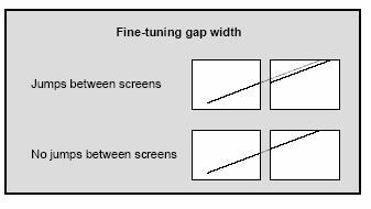
23 Jumps between screens No jumps between screens compensating for gaps between screens Setting gap width To set the gap width, open the OSD. Enter the SYSTEM submenu, and open the GAP submenu. In this menu, you can set the vertical and horizontal gap width (in pixels). After you are finished, use the exit button to leave the menus, and close the OSD. Calculating gap width To calculate the gap width, first check the output resolution of the V-Match. You can find the output resolution in the V-Match OSD menu under CONSOLE->VIDEO OUTPUT. 23

24 As an example, assume the output video mode is WUXGA (1920x1200). This means the horizontal resolution is 1920 and the vertical resolution is Then, measure the visible width of the actual output image of your display. Divide the output resolution by the width to get the pixel density, that is, the number of pixels per centimeter on your screen. width: 49.5cm height: 31cm hier hätte ich lieber einen echten Monitor fotografiert, aber das war mir zu viel Aufwand For example, your screen is 49.5cm wide, and 31cm high. Thus, we get a horizontal pixel density of and a vertical pixel density of 1920 px 49.5cm 1200 px 31cm = = px cm px cm The values for horizontal and vertical pixel density are usually equal. In the example, the deviation is due to small errors of measurement. Since the calculation is only used to get 24

25 an approximate value for the gap width, you can use the same value for horizontal and vertical pixel density if they are similar. You can fine-tune the gap width later. In the example, the horizontal and vertical pixel density values are very close to each other, so rounding up, the pixel density is 39 pixels per centimeter both horizontally and vertically. Next, measure the gap between the image on one screen and the image on the next screen. Multiply that gap width by the pixel density from the previous step to obtain the gap width in pixels. vertical gap width: 3.6cm horizontal gap width: 4cm Kite photograph by Ingorrr used under Creative Commons Attribution license In this example, the gap between the edges of the visible image is 4cm wide horizontally, and the vertical gap is 3.6cm wide. Thus, the gap widths are px 39 4cm = 156 px cm for a horizontal gap of 156 pixels, and px cm = px cm vertical gap, rounded to 148 pixels. Set these values in the gap menu. To verify and fine-tune your settings, you can use a picture with diagonal lines, and choose a preset that enlarges the input image so that the diagonal lines cross the boundaries between displays. You can then adjust the gap settings until the lines appear straight, and without jumps. Use a ruler or other straight object to check if the lines are perfectly aligned. 25
26 26


27 Free Presets Free presets offer the greatest flexibility for a video wall setup. To define a free preset, for each display, the exact section of the input image is specified. You can create a video wall using a mixed display setup with any kind of display, for example, flat panel displays, CRTs, LED panels, LCD TVs, and beamers of any screen size, resolution and aspect ratio, digital as well as analog. In addition to mixing different displays, V-Match allows arranging displays freely to create individually shaped video walls including overlapping displays. Overlapping displays To use free presets, set the preset type in the V-Match OSD menu to Free in SYSTEM- >PRESET TYPE. 27
28 Use the V-Match Control program to control and configure free presets. Please see the next section, Using the Control Program for a description of the V-Match Control program. 28
29 Using the Control Program Installation A windows PC is required, to run the V-Match Control program. To install, copy the folder Control Program from the enclosed CD to your hard disk. To run the program, open the file VMatchControl.exe. Setup Connect the enclosed serial cable to the upper RS-232 port on the V-Match main unit. Connect the cable to a serial port of your computer. You can choose the COM port in the Control Program under File->Settings... The user interface Display List View Toolbar Preset Edit View 29

30 The tool bar Using the Preset drop down menu in the tool bar, you can choose which preset to edit. When you choose a preset, the edit view and display list view will show that preset, and the preset will also be activated on the V-Match system and be visible on the video wall. The Channel drop down allows you to choose which channel to display in the edit view. This setting only controls the view shown in the control program. It has no effect on the V-Match units. To change which channel a V-Match unit displays, use the Edit window (described in section 3.3 The Preset Editor) Connection status The V-Match Control program can be used to control a V-Match system connected to the PC the program is running on. It can also be used without a V-Match system to configure the presets. If the program is connected to a V-Match system, changes in presets take effect immediately. If the program is not connected, changes in presets are stored on the PC, and are transferred automatically to the V-Match system as soon as the program is connected. You can choose whether the V-Match Control program should automatically attempt to connect when you start it. To control this setting, Choose File->Settings... from the main menu, and check the checkbox next to Connect to V-Match at startup. The connect/disconnect buttons allow you to connect to or disconnect from the V-Match system. disconnect connect The connection status buttons indicate whether the V-Match Control program is currently connected to the V-Match system. 30
31 The Display List The Display List shows all displays, and the settings for the displays defined in the current preset. Left-clicking on a screen selects that screen. Right-clicking on a screen opens a context menu which allows you to change the aspect ratio, input channel, and other properties of that screen (see 3.3 The Preset Editor). 31

32 The Preset Edit View Preset Edit View The Preset Edit View displays one input channel at a time. You can switch the displayed input channel with the Channel drop down menu. In the Preset Edit View, the displays are shown as rectangles, with the display name in the upper left corner. Display names show the V-Match unit and board the display is connected to. If you want to use both input channels in the same preset, use the Channel drop down to switch between the views of the two channels. Set the sizes for all displays showing input channel 1 in channel 1, and all displays showing the second channel in channel 2. 32

33 A preset with two channels Channel 1 33

34 Channel 2 The Preset Edit View lets you change the position and size of the section of the input image each screen displays. Use the mouse to drag and resize the sections. Changing position and size this way, you can quickly configure presets to achieve an approximation of the preset you want to create. Right click on a screen (in the Display List or the Preset View) to open the following context menu. In the context menu, you can add or remove screens, open the Edit window, and choose the input channel the display shows. Please see section Editing display parameters for a description of the Edit window. 34

35 After you have created an approximation of your preset using the Preset Edit View, fine tune each preset by following the next steps. Input channel settings First, configure the settings for the input channels according to your video sources. To change input channel settings, go to Video->Input Channels... in the main menu. In this menu, you can choose the input aspect ratio, and change the picture that is displayed as a background image. Setting the correct aspect ratio ensures distortion-free display on your video wall. Four aspect ratios are commonly used: 4:3 640 x x x x x : x : x 768 HDTV(1920 x 1080) 35
36 16: x x 1200 Common aspect ratios and resolutions Set the input aspect ratio according to the resolution of your video sources. A background image that shows the content you wish to display on the video wall will make creating presets more comfortable by giving you a realistic preview in the Preset Edit View. We suggest you import a frame from your video, or a screenshot of the computer you want to show on the video wall. The background image must be a Bitmap file (with extension.bmp ). After configuring the input channels, set the values for your displays. Editing display parameters For each output screen connected to the system, there are a number of parameters that control what is displayed on the screen. These settings can have different values from preset to preset. Use the Edit window to control these settings. The item Edit... in the context menu of the displays opens the Edit Window. 36

37 The following settings can be chosen per preset for each display: position size aspect ratio input channel output resolution position and size of the section of the input image this display shows optional; a fixed aspect ratio which the program will maintain. This prevents distortions of the image by ensuring the section from the input image always has the correct aspect ratio. which input channel to display the output resolution Position in input image Specifies the part of the input image to display on the screen. Obtaining these values involves some calculations, which are described in section Position and size. 37
38 y x height width Aspect ratio This setting controls the way the V-Match Control program allows screens to be resized. If a fixed aspect ratio is chosen, the program always maintains that ratio. For a more detailed discussion of aspect ratios, see section Aspect ratio (page 38) Output video mode This setting controls the output video mode, i.e. resolution and refresh rate of one display. For each display in your setup, you can choose a different video mode. Note Since a display does not change from preset to preset, setting the output resolution of a display affects that display across all presets. In the Edit window, you can specify the section of the input signal to be displayed by the screen. You can also change the aspect ratio and choose which channel to display. The settings in the boxes labeled section in input image, aspect ratio, and input channel apply to the active preset only (selected in the tool bar). The settings in the display box apply to the selected display across all presets. Note We recommend setting the output resolution to your display s native resolution, and setting the aspect ratio to as display. This ensures that the displays will show distortionfree video as you move and resize them. 38
39 From the context menu, you can also set the channel and aspect ratio for a display, without having to use the Edit window. Setting the correct aspect ratio for a display ensures that the output image will not be distorted on that display. Position and size Units Size and position are specified in relative units. This means that the units do not directly correspond to pixel values. Rather, they are relative to the width of the input image. A width of 9999 is exactly as wide as the input image. Because displays are not quadratic, but rectangular, the height of the input image in units depends on the input video mode. 39
40 black border 9999 x input image (5:4) input image vertically centered y The input image is vertically centered in the coordinate system, which means that the visible portion of the image will begin at a y-value greater than 0. The exact value depends on the aspect ratio. This way, if the input video mode changes, the displays will remain centered on the input image. aspect ratio minimum x value maximum x value width height minimum y value maximum y value 5:4 0 9,999 10,000 8,000 1,000 8,999 4:3 0 9,999 10,000 7,500 1,250 8,749 16:9 0 9,999 10, ,811 16:10 0 9,999 10, ,124 40
41 Note The units are equal in the vertical and horizontal directions, and are relative to the horizontal resolution. For example, if the input signal has a resolution of 1920x1200, then a width of 9999 will be 1920 pixels (a height of 9999 will be also be 1920 pixels, resulting in black borders at the top and bottom of the image). The simplest analogy for the units is to think about them as percentage values of the input signal width. Note The values for size and position specify the coordinates of the section from the input image a display shows. This means that reducing the width and height of a rectangle in the Edit View will cause the display to zoom in and show a smaller portion of the input image. How To Set Up a Video Wall To set up a video wall with a free setup, follow the steps below. 1. Set input aspect ratio. Find out the aspect ratio of input channels 1 and 2. Refer to section Input Channel Settings for a table of common resolutions and their aspect ratios. Go to Video->Input Channels... in the main menu. In the window, set the aspect ratios for the input channels. 2. Set output resolution for each display. Find out the native resolution for your displays. Open the Edit window from the context menu for each display, and set the output resolution to the native resolution of your display. 3. Measure physical video wall size. Measure the width and height of your video wall. Measure from the edge of the leftmost display to the edge of the rightmost display, and from the top edge of the topmost display to the bottom of the display at the bottom. When measuring, take care to measure only the visible section of the screens, that is, exclude the frames around the displays at the video wall s edges. Calculate your video wall s aspect ratio to help you define the section of the input 41
42 image you want to display on your video wall. Usually, the ratio will differ from the input aspect ratio. Note: Up to this point, the settings you have obtained apply to the video wall, and are the same for all presets you will create for that particular wall. Steps 4-8 apply to one particular preset. Repeat these steps for each preset you want to set up. 4. Define input image section to display Choose the section of the input image to display. You can either choose to display a part of the input image, or to show as much of the input image as possible. If you choose to display as much of the contents of the input image as possible, and the aspect ratio of your video wall differs from the aspect ratio of your input image, you have two choices for the section of the input image. - show entire image, with black bars - show the largest possible part of the input image, without black bars Where the black bars appear depends on the relation of the video wall s aspect ratio to the input signal s aspect ratio. If your video wall is wider than the input image, the black bars will be on the left and right sides of the image. If your video wall is narrower than the input signal, the black bars will be on the top and bottom of the image. Note: We recommend leaving some space on the edges of your input image in this step. Later, your will have some reserve space left for fine-tuning the settings. How to determine the size of the section to show, and how to convert the size into units is explained in detail in section 5. Calculate Units per Centimeter by dividing video wall width by measure size for each display (hint: Our excellent testing from sales team has discovered that displays of the same type have the same size) 7. position a. calculate x-position by measuring from the left edge of the video wall and converting from cm to units Note: add offset enter into the x-field b. calculate y-position by measuring from the top edge of the video wall and converting from cm to units 42
43 Note: add offset enter into the y-field 8. fine-tune a. Create a test image with a lot of diagonalines. b. Choose a display as starting point (we recommend the central display) c. fine tune all displays starting from the first display adjust position (x/y coordinates) d. there is no d. Example As an example, consider the video wall shown on the first page. The image displayed on the video wall is composed of sections from the input image. Since the coordinates are anchored to the input image, we get the following coordinate system. The input image is an HDTV signal, with a resolution of 1920x1080 and an aspect ratio of 16:9. Since the input image is centered vertically, the y-coordinate of the visible image is greater than 0, in our case,
44 x 2187 input image 7811 y In this case, we chose to display not the whole input image, but to leave out some space at the top and sides. We know the input image is 1920x1080 pixels. To define the area to display, we first need to know the size of the video wall. More precisely, we need the aspect ratio of the video wall, because we can enlarge or reduce the section we want to display, but we have to respect the aspect ratio, or the picture will appear distorted. We then measure the width and height of our video wall. We measure from the edge of the leftmost display to the edge of the rightmost display, and from the top edge of the topmost display to the bottom of the display at the bottom. When measuring, take care to measure only the visible section of the screens, that is, exclude the frames around the displays at the video wall s edges. 220 cm 120 cm The area shown by the monitor wall has an aspect ratio of 220cm : 120cm, which corresponds to an aspect ratio of 16.5:9. This means it is a little wider than our 16:9 input image. We have the choice of showing an image that is clipped at the top and/or bottom edges, or of showing the complete input image, with black bars at the sides. In this case, we chose to show only a portion of the input image (the racing car, and omit a part of the not-so-interesting scenery. 44
45 Picture 12: clipping left/right vs. black bars. Note that in the example for clipping, the portion to display was chosen a little lower than the center of the input image, to have all of the car visible The section of the input image in pixels To calculate the portion of the input image we want to display on the video wall, we decide which section of the input image to show on the video wall. In pixels, this section is x: y: We convert these values to our coordinate system by first dividing by the width of the input image in pixels (1920), and then multiplying by the width of the coordinate system (9999) = = For the y-values, we also have to add the offset of
46 = = The section of the input image converted to the coordinate system To calculate the coordinates for a single screen, we need to measure the physical size of the screens in the video wall, and the gaps between the screens. 58 cm 40 cm 30 cm Taking the topmost display as an example, we measure the distance from the top (0, for the topmost display), from the leftmost display(58cm), and width (40cm) and height (30cm) of the display. Take care to always measure from the active part of the screen, not from the frame. The total width of the video wall is 220cm, which corresponds to 9368 units in our section of the input image so we can transform the physical size into coordinates by dividing by the physical wall width (220cm), and multiplying by the wall width in the 46
, so we do not need to calculate the height of the screen.")
47 coordinates (9368). Here, we again use the total width as the base to transform both height and width, and again we add the offset of 2187 to the y-coordinate. x-coordinate: 58cm 9368 = cm y-coordinate: 0 cm = cm width: 9368 = cm We know the display s native resolution (XGA, 1024x768), so we do not need to calculate the height of the screen. When we enter the output resolution and set the aspect ratio to as display, the program will automatically adjust the height of the section according to the width and aspect ratio. We then set the values in the edit window. Repeat these calculations for all displays. The advantage of this system is that it is resolution-independent. A preset for a UXGA (1600x1200) input signal will work equally with input signals in XGA (1024x768), 47
48 SVGA(800x600), or VGA (640x480). Even if the input aspect ratio changes, the same preset will still result in a viewable image, although possibly with black borders at the top and bottom. How to determine the input image section When determining the dimensions of the input image section you width to display, the goal is to get measurements relative to the width and height of the input image. This is because the input coordinate system is relative to the input image, the total width of the input image being 9999U. If you want to only half of the width of the input image, your section of the input image will be 5000U wide. Another thing to keep in mind when determining the section from the input image is that the width and height of the section need to have the same aspect ratio as your video wall, for the image to be displayed without distortion. This means that if you choose the width, the height of the section will be dictated by your video wall s aspect ratio. Conversely, you can choose the height first, but then the width will be fixed. TODO: hier fehlt noch die Erklärung wie man dann die Breite nach der Höhe oder umgekehrt bestimmt To choose the section of the input screen, you can open a screenshot from the input image in a graphical editor, and choose the section you want to display. Most editors will display the coordinates of the selection in pixels. Take the pixel values for x- and y- position, width and height of the selection and the width and height of the total image. Then, calculate what portion of the total width of the image your coordinates represent: divide the total width by the coordinate value. Example Setups Reference: The OSD, Settings, and All the Rest OSD Menu(s) 48
49 Scope of Supply v-match main: kabel kabel kabel CD with - V-Match Control program - ConfDev configuration tool V-Match Manual (this document what you are reading right now) ConfDev manual 49
KRAMER ELECTRONICS LTD. USER MANUAL
 KRAMER ELECTRONICS LTD. USER MANUAL MODEL: Projection Curved Screen Blend Guide How to blend projection images on a curved screen using the Warp Generator version K-1.4 Introduction The guide describes
Table of content. Table of content Introduction Concepts Hardware setup...4
 Table of content Table of content... 1 Introduction... 2 1. Concepts...3 2. Hardware setup...4 2.1. ArtNet, Nodes and Switches...4 2.2. e:cue butlers...5 2.3. Computer...5 3. Installation...6 4. LED Mapper
2G Video Wall Guide Just Add Power HD over IP Page1 2G VIDEO WALL GUIDE. Revised
 2G Video Wall Guide Just Add Power HD over IP Page1 2G VIDEO WALL GUIDE Revised 2016-05-09 2G Video Wall Guide Just Add Power HD over IP Page2 Table of Contents Specifications... 4 Requirements for Setup...
The Extron MGP 464 is a powerful, highly effective tool for advanced A/V communications and presentations. It has the
 MGP 464: How to Get the Most from the MGP 464 for Successful Presentations The Extron MGP 464 is a powerful, highly effective tool for advanced A/V communications and presentations. It has the ability
OPERATING GUIDE. HIGHlite 660 series. High Brightness Digital Video Projector 16:9 widescreen display. Rev A June A
 OPERATING GUIDE HIGHlite 660 series High Brightness Digital Video Projector 16:9 widescreen display 111-9714A Digital Projection HIGHlite 660 series CONTENTS Operating Guide CONTENTS About this Guide...
G-106Ex Single channel edge blending Processor. G-106Ex is multiple purpose video processor with warp, de-warp, video wall control, format
 G-106Ex Single channel edge blending Processor G-106Ex is multiple purpose video processor with warp, de-warp, video wall control, format conversion, scaler switcher, PIP/POP, 3D format conversion, image
G-106 GWarp Processor. G-106 is multiple purpose video processor with warp, de-warp, video wall control, format conversion,
 G-106 GWarp Processor G-106 is multiple purpose video processor with warp, de-warp, video wall control, format conversion, scaler switcher, PIP/POP, 3D format conversion, image cropping and flip/rotation.
VGA to DVI-I. Scaler Box CP-252. Operation Manual
 VGA to DVI-I Scaler Box Operation Manual Output PC+HDTV/YPbPr Digital:PC+HDTV : PC+HDTV/YPbPr PC+HDTV/YPbPr Digital:PC+HDTV : PC+HDTV/YPbPr : PC+HDTV/YPbPr Digital:PC+HDTV : PC+HDTV/YPbPr Cypress's high
DVI Digital scaler with ultra high bandwidth ID#442
 DVI Digital scaler with ultra high bandwidth ID#442 Operation Manual Introduction Congratulations on your purchase of the DVI Digital scaler with ultra high bandwidth. Please read this to become familiar
Setting Up the Warp System File: Warp Theater Set-up.doc 25 MAY 04
 Setting Up the Warp System File: Warp Theater Set-up.doc 25 MAY 04 Initial Assumptions: Theater geometry has been calculated and the screens have been marked with fiducial points that represent the limits
Statement SmartLCT User s Manual Welcome to use the product from Xi an NovaStar Tech Co., Ltd. (hereinafter referred to as NovaStar ). It is our great
. It is our great") LED Display Configuration Software SmartLCT User s Manual Software Version: V3.0 Rev3.0.0 NS110100239 Statement SmartLCT User s Manual Welcome to use the product from Xi an NovaStar Tech Co., Ltd. (hereinafter
LED Display Configuration Software SmartLCT User s Manual Software Version: V3.0 Rev3.0.0 NS110100239 Statement SmartLCT User s Manual Welcome to use the product from Xi an NovaStar Tech Co., Ltd. (hereinafter
VSP 516S Quick Start
 VIEWSIZE THE WORLD VSP 516S Quick Start Max 2048 1152@60Hz/2560 816 60Hz input/output resolution User customize output resolution 3G/HD/SD-SDI input Multiple cascade mapping for super resolution Seamless
All-rounder eyedesign V3-Software
 All-rounder eyedesign V3-Software Intuitive software for design, planning, installation and servicing of creative video walls FOR PRESENTATION & INFORMATION FOR BROADCAST ALL-ROUNDER eyedesign SOFTWARE
G-700LITELite multiple Channel warping processor
 G-700LITELite multiple Channel warping processor Version: 2.01, Date: 2017-07 G-700Lite is a warping processor with the ability to provide multiple processing modules to control from 1 to 4 projectors
PLV-Z2 ROLL THE FILM FOR THE FUTURE!
 ROLL THE FILM FOR THE FUTURE! With the new PLV-Z2, SANYO has introduced a home cinema projector that is sure to capture the hearts of all home cinema fans. The latest technology, outstanding image quality,
VSP 198CVS Quick Start
 VIEWSIZE THE WORLD VSP 198CVS Quick Start Max 2048 1152@60Hz/2560 1152 50Hz input/output resolution User customize output resolution 3G/HD/SD-SDI input Multiple cascade mapping for super resolution DVI
EZwindow4K-LL TM Ultra HD Video Combiner
 EZwindow4K-LL Specifications EZwindow4K-LL TM Ultra HD Video Combiner Synchronizes 1 to 4 standard video inputs with a UHD video stream, to produce a UHD video output with overlays and/or windows. EZwindow4K-LL
isync HD & isync Pro Quick Reference Guide isync HD isync Pro Digital Video Processor and Video/Audio Switcher
 isync HD & isync Pro Digital Video Processor and Video/Audio Switcher Quick Reference Guide isync HD Key Digital, led by digital video pioneer Mike Tsinberg, develops and manufactures high quality, cutting-edge
2013, 2014 Hewlett-Packard Development Company, L.P.
 User Guide 2013, 2014 Hewlett-Packard Development Company, L.P. The only warranties for HP products and services are set forth in the express warranty statements accompanying such products and services.
7thSense Design Delta Media Server
 7thSense Design Delta Media Server Channel Alignment Guide: Warping and Blending Original by Andy B Adapted by Helen W (November 2015) 1 Trademark Information Delta, Delta Media Server, Delta Nano, Delta
KRAMER ELECTRONICS LTD. USER GUIDE MODEL: VP-790 Blending Projected Images on a Flat Screen. P/N: Rev 1
 KRAMER ELECTRONICS LTD. USER GUIDE MODEL: VP-790 Blending Projected Images on a Flat Screen P/N: 2900-300215 Rev 1 Contents 1 Introduction 1 2 Setting the Basic System 2 2.1 Optical Alignment 3 3 Setting
G406 application note for projector
 G406 application note for projector Do you have trouble in using projector internal warp and edge blending function? Inconvenient in multiple signal source connection System resolution is not enough after
VSP 168HD Quick Start
 VSP 168HD Quick Start Support 10Gbps of transmission rate Support HDBaseT protocols and standards Support USB upgrade Max 2048 1152@60Hz/2560 816 60Hz input/output resolution Support custom output resolution
VGA to DVI-I. Scaler Box CP-252. Operation Manual
 VGA to DVI-I Scaler Box CP-252 Operation Manual Cypress's high performance scaler/processor family Spec. Signal Type Connector Model Input Output Input Output Format Input Output CP-251 Analog Analog HD-15F
A+ Certification Guide. Chapter 7 Video
 A+ Certification Guide Chapter 7 Video Chapter 7 Objectives Video (Graphics) Cards Types and Installation: Describe the different types of video cards, including PCI, AGP, and PCIe, and the methods of
DVI/PC/HD to DVI/PC Scaler - ID# 15320
 DVI/PC/HD to DVI/PC Scaler - ID# 15320 Operation Manual Introduction This DVI/PC/HD to DVI/PC Scaler is capable of scaling and sourceswitching from PC (VGA), Component Video (SD/HD) and DVI input signals
PC/HDTV to PC/HDTV converter (CP-251F)
") PC/HDTV to PC/HDTV converter (CP-251F) Operation Manual This Converter has been especially modified to also accept RGsB Sync on Green Operation Controls and Functions Front Panel 1. Reset/ and +- The and
PC/HDTV to PC/HDTV converter (CP-251F) Operation Manual This Converter has been especially modified to also accept RGsB Sync on Green Operation Controls and Functions Front Panel 1. Reset/ and +- The and
ivw-fd133 Video Wall Controller MODEL: ivw-fd133 Video Wall Controller Supports 3 x 3 and 2 x 2 Video Wall Array User Manual Page i Rev. 1.
 MODEL: ivw-fd133 Video Wall Controller Supports 3 x 3 and 2 x 2 Video Wall Array User Manual Rev. 1.01 Page i Copyright COPYRIGHT NOTICE The information in this document is subject to change without prior
OPERATING GUIDE. M-Vision Cine 3D series. High Brightness Digital Video Projector 16:9 widescreen display. Rev A August A
 OPERATING GUIDE M-Vision Cine 3D series High Brightness Digital Video Projector 16:9 widescreen display 112-022A Digital Projection M-Vision Cine 3D series CONTENTS Operating Guide CONTENTS About this
ivw-fd122 Video Wall Controller MODEL: ivw-fd122 Video Wall Controller Supports 2 x 2 Video Wall Array User Manual Page i Rev. 1.
 MODEL: ivw-fd122 Video Wall Controller Supports 2 x 2 Video Wall Array User Manual Rev. 1.01 Page i Copyright COPYRIGHT NOTICE The information in this document is subject to change without prior notice
D-ILA PROJECTOR DLA-G15 DLA-S15
 D-ILA PROJECTOR DLA-G15 Outstanding Projection Im Breakthrough D-ILA projector offers high-contrast 350:1, 1500 ANSI lumen brightness and S-XGA resolution Large-size projection images with all the sharpness
RMS 8424S Quick Start
 VIEWSIZE THE WORLD RMS 8424S Quick Start Standard 4 unit rack mount size 8 inch LCD 2 1024 3 (RGB) 600 16:9 / 4:3 adjustable SDI/HDMI embedded audio output via 3.5mm earphone socket Support SDI/DVI audio
Subtitle Safe Crop Area SCA
 Subtitle Safe Crop Area SCA BBC, 9 th June 2016 Introduction This document describes a proposal for a Safe Crop Area parameter attribute for inclusion within TTML documents to provide additional information
PROFESSIONAL D-ILA PROJECTOR DLA-G11
 PROFESSIONAL D-ILA PROJECTOR DLA-G11 A new digital projector that projects true S-XGA images with breakthrough D-ILA technology Large-size projection images with all the sharpness and clarity of a small-screen
AC334A. VGA-Video Ultimate BLACK BOX Remote Control. Back Panel View. Side View MOUSE DC IN BLACK BOX ZOOM/FREEZE POWER
 AC334A BLACK BOX 724-746-5500 VGA-Video Ultimate BLACK BOX 724-746-5500 Zoom Position PAL ZOOM/FREEZE POWER FREEZE ZOOM NTSC/PAL SIZE RESET POWER Size Power Remote Control DC IN MOUSE MIC IN AUDIO OUT
PROFESSIONAL D-ILA PROJECTOR DLA-G11
 PROFESSIONAL D-ILA PROJECTOR DLA-G11 A new digital projector that projects true S-XGA images with breakthrough D-ILA technology Large-size projection images with all the sharpness and clarity of a small-screen
VideoClock. Quick Start
 VideoClock Quick Start Connect Limitimer, thetimeprompt, or PerfectCue to the dongle and the dongle to the USB port. (Note: Both the dongle and software are matched to the respective device. Do not mix.
AC335A. VGA-Video Ultimate Plus BLACK BOX Back Panel View. Remote Control. Side View MOUSE DC IN OVERLAY
 AC335A BLACK BOX 724-746-5500 VGA-Video Ultimate Plus Position OVERLAY MIX POWER FREEZE ZOOM NTSC/PAL SIZE GENLOCK POWER DC IN MOUSE MIC IN AUDIO OUT VGA IN/OUT (MAC) Remote Control Back Panel View RGB
Manual Version Ver 1.0
 The BG-3 & The BG-7 Multiple Test Pattern Generator with Field Programmable ID Option Manual Version Ver 1.0 BURST ELECTRONICS INC CORRALES, NM 87048 USA (505) 898-1455 VOICE (505) 890-8926 Tech Support
FIRMWARE RELEASE NOTE
 Products VRC300 Date Nov 18, 2015 Version 2.02.08 The version(s) indicated here above has (have) been tested and validated by the Technical Support Department. Version 2.02.08 Technical notes New Features
Video Scaler Pro with RS-232
 Video Scaler Pro with RS-232 - ID# 783 Operation Manual Introduction Features The Video Scaler Pro with RS-232 is designed to convert Composite S-Video and YCbCr signals to a variety of computer and HDTV
SC-HD-2A HDMI Scaler & Audio Embedder / Extractor
 User s Manual SC-HD-2A HDMI Scaler & Audio Embedder / Extractor Scale HDMI or DVI video Embed Digital or Analog Audio into HDMI output Extract (De-embed) Digital and Analog Audio from HDMI input UMA1246
USER MANUAL. HIGHlite Laser 3D Series INSTALLATION AND QUICK-START GUIDE CONNECTION GUIDE OPERATING GUIDE REFERENCE GUIDE
 HIGHlite Laser 3D Series High Brightness Digital Video Projector USER MANUAL INSTALLATION AND QUICK-START GUIDE CONNECTION GUIDE OPERATING GUIDE REFERENCE GUIDE 114-913B Digital Projection HIGHlite Laser
CONTENT Product Introduction... 2 Packing Configuration...3 Hardware Orientation... 4 Front Panel... 4 Back Panel... 6 Using Your Product... 7 Content
 VENUS X1PRO Quick Start 4K input support in DP, HDMI and DVI Input standard 2K formats Scale and switch seamlessly between 2K and 4K inputs Output to any format 2K or 4K EDID management on board HDCP 2.0
CORIO master C3-540 Series
 Key Features Manage up to 4 independent video walls Uses CORIOgrapher; simple, powerful software interface Universal DVI Inputs/Outputs: (HDMI/CV/YC/RGB/YPbPr) SDI Inputs/Outputs: SD/HD-SDI/3G-SDI to 1080p60
TV Character Generator
 TV Character Generator TV CHARACTER GENERATOR There are many ways to show the results of a microcontroller process in a visual manner, ranging from very simple and cheap, such as lighting an LED, to much
HD Leeza. Quick Setup Guide
 Page 1 of 15 Model KD-HD1080P Key Digital Video Processor Quick Setup Guide Have a question or a technical issue with your set-up? Call the Key Digital Hotline at: 866-439-8988 or 203-798-7187 E-mail the
DVI to DVI-I Scaler Box Operation Manual
 DVI to DVI-I Scaler Box Operation Manual Introduction This unit is a DVI to DVI- I high performance two way Scaler Box that converts DVI-D input into analog + digital PC or HDTV output. Precautions 1.
The only warranties for HP products and services are set forth in the express warranty statements accompanying such products and services.
 The only warranties for HP products and services are set forth in the express warranty statements accompanying such products and services. Nothing herein should be construed as constituting an additional
Video Wall Display User s Manual
 Video Wall Display User s Manual Manual Version TL46-55H1.1 Our Full Product Range Page 1 Safety Instructions Please handle the display with extreme care, significant impact will damage the LCD panel.
High-Definition Scaler. GTV-HIDEFS. User Manual
 High-Definition Scaler GTV-HIDEFS User Manual www.gefentv.com Technical Support: Telephone (818) 772-9100 (800) 545-6900 Fax (818) 772-9120 Technical Support Hours: 8:00 AM to 5:00 PM Monday thru Friday.
LM-WPS41 HD Caption Adder. User. Manual
 LM-WPS41 HD Caption Adder User Manual 1 Table of Contents 1. Installation Notes 3 2.Product Introduction 5 3. Machine installation 7 4. Software debugging 8 5. Remote Control Description 12 Chapter One
HD Mate Scaler USER MANUAL.
 HD Mate Scaler USER MANUAL www.gefen.com ASKING FOR ASSISTANCE Technical Support: Telephone (818) 772-9100 (800) 545-6900 Fax (818) 772-9120 Technical Support Hours: 8:00 AM to 5:00 PM Monday through Friday
CCE900-IP-TR. User s Guide
 CCE900-IP-TR CCE900-IP-T & CCE900-IP-R User s Guide i-tech Company LLC TOLL FREE: (888) 483-2418 EMAIL: info@itechlcd.com WEB: www.itechlcd.com 1. Introduction The CCE900-IP-T & CCE900-IP-R is a solution
iii Table of Contents
 i iii Table of Contents Display Setup Tutorial....................... 1 Launching Catalyst Control Center 1 The Catalyst Control Center Wizard 2 Enabling a second display 3 Enabling A Standard TV 7 Setting
KRAMER ELECTRONICS LTD. USER GUIDE MODEL: VP-790 Blending Projected Images on a Curved Screen. P/N: Rev 1
 KRAMER ELECTRONICS LTD. USER GUIDE MODEL: VP-790 Blending Projected Images on a Curved Screen P/N: 2900-300214 Rev 1 Contents 1 Introduction 1 2 Setting the Basic System 2 2.1 Optical Alignment 3 3 Setting
Projector Management Application Version 7.00 Instruction Guide
 Projector Management Application Version 7.00 Instruction Guide Contents 1 INTRODUCTION... 4 1.1 OUTLINE... 4 1.2 SYSTEM... 4 2 INSTALLATION... 5 2.1 SYSTEM REQUIREMENTS... 5 2.2 PROJECTOR MANAGEMENT APPLICATION
Composite to HDMI Scaler
 Composite to HDMI Scaler GTV-COMPSVID-2-HDMIS User Manual Version A2 gefen.com ASKING FOR ASSISTANCE Technical Support: Telephone Email 1-707-283-5900 1-800-472-5555 support@gefen.com Technical Support
Kramer Electronics, Ltd. USER MANUAL. Model: VP-724DS. Seamless Switcher / Scaler
 Kramer Electronics, Ltd. USER MANUAL Model: VP-724DS Seamless Switcher / Scaler Contents Contents 1 Introduction 1 2 Getting Started 1 3 Overview 2 4 Your VP-724DS Seamless Switcher / Scaler 3 5 Connecting
2D/3D Multi-Projector Stacking Processor. User Manual AF5D-21
 2D/3D Multi-Projector Stacking Processor User Manual AF5D-21 Thank you for choosing AF5D-21 passive 3D processor. AF5D-21 is an advanced dual channel passive 3D processor with 10 bits high end scaler and
HIGHlite Laser 3D Series High Brightness Digital Video Projector
 HIGHlite Laser 3D Series High Brightness Digital Video Projector 4INSTALLATION AND QUICK-START GUIDE 4CONNECTION GUIDE 4OPERATING GUIDE 4REFERENCE GUIDE 114-913C About This Document Follow the instructions
USER MANUAL. Vidifox Document Camera DV 550S
 Vidifox Document Camera DV 550S USER MANUAL Please read this User Manual thoroughly before you use the document camera. Keep the CD-ROM in a convenient place so you can use it quickly if you need to. Please
P-2 Installing the monitor (continued) Carry out as necessary
 Carry out as necessary") P-2 Installing the monitor (continued) Carry out as necessary Using the monitor without the bezel MDT552S satisfies the UL requirements as long as it is used with the bezel attached. When using the monitor
P-2 Installing the monitor (continued) Carry out as necessary Using the monitor without the bezel MDT552S satisfies the UL requirements as long as it is used with the bezel attached. When using the monitor
TABLE OF CONTENTS. 4.1 Front Panel Rear Panel OSD Operation Rest Functionality General Specification...
 TABLE OF CONTENTS 1. Introduction... 1 2. Features... 1 3. Package Contents... 1 4. Operation Controls and Functions... 2 4.1 Front Panel... 2 4.2 Rear Panel... 3 4.3 OSD Operation... 4 5. Rest Functionality...
ENERGY STAR Program Requirements Product Specification for Televisions. Eligibility Criteria Version 5.3
 ENERGY STAR Program Requirements Product Specification for Televisions Eligibility Criteria Version 5.3 Following is the Version 5.3 ENERGY STAR Product Specification for Televisions. A product shall meet
SC-CSV-HDMI Composite & S-Video To HDMI Video Processor
 SC-CSV-HDMI Composite & S-Video To HDMI Video Processor UMA1173 Rev. NC CUSTOMER SUPPORT INFORMATION Order toll-free in the U.S. 800-959-6439 FREE technical support, Call 714-641-6607 or fax 714-641-6698
Software Quick Manual
 XX177-24-00 Virtual Matrix Display Controller Quick Manual Vicon Industries Inc. does not warrant that the functions contained in this equipment will meet your requirements or that the operation will be
VENUS X1PRO-E Quick Start
 VENUS X1PRO-E Quick Start 4K input support in DP, HDMI and Dual Link DVI Support 8K x 1K, 4K x 2K Seamless Splicing EDID management Modular 2K input: Three slots for 2K input options 2K-2K and/or 4K-2K
Lab Determining the Screen Resolution of a Computer
 Lab 1.3.3 Determining the Screen Resolution of a Computer Objectives Determine the current screen resolution of a PC monitor. Determine the maximum resolution for the highest color quality. Calculate the
Kramer Electronics, Ltd. USER MANUAL. Models: VP-720DS, Seamless Switcher / Scaler VP-723DS, Seamless Switcher / Scaler
 Kramer Electronics, Ltd. USER MANUAL Models: VP-720DS, Seamless Switcher / Scaler VP-723DS, Seamless Switcher / Scaler Contents Contents 1 Introduction 1 2 Getting Started 1 3 Overview 1 4 Your Seamless
Video to SXGA Converter Box ID#475
 Video to SXGA Converter Box ID#475 Operation Manual Introduction The Video to SXGA Converter Box is a composite video signal. S-Video signal and YCbCr signal format converter for AV System (Such as DVD.
Technical Developments for Widescreen LCDs, and Products Employed These Technologies
 Technical Developments for Widescreen LCDs, and Products Employed These Technologies MIYAMOTO Tsuneo, NAGANO Satoru, IGARASHI Naoto Abstract Following increases in widescreen representations of visual
Reference Guide. Multi-Screen Modes. This document describes Multi-Screen Modes (AUX/Split/Span/Dual) of the V-1600HD.
 of the V-1600HD.") Multi-Screen Modes Reference Guide This document describes Multi-Screen Modes (AUX/Split/Span/Dual) of the V-1600HD. Copyright 2010 ROLAND CORPORATION All rights reserved. No part of this publication may
Multi-Screen Modes Reference Guide This document describes Multi-Screen Modes (AUX/Split/Span/Dual) of the V-1600HD. Copyright 2010 ROLAND CORPORATION All rights reserved. No part of this publication may
CP-255ID Multi-Format to DVI Scaler
 CP-255ID Multi-Format to DVI Scaler Operation Manual DISCLAIMERS The information in this manual has been carefully checked and is believed to be accurate. Cypress Technology assumes no responsibility
A/V Cinema Scaler Pro II
 A/V Cinema Scaler Pro II EXT-AVCINEMAAD User s Manual ASKING FOR ASSISTANCE Technical Support: Telephone (818) 772-9100 (800) 545-6900 Fax (818) 772-9120 Technical Support Hours: 8:00 AM to 5:00 PM Monday
PLUSTV 1680ex USER S MANUAL
 PLUSTV 1680ex USER S MANUAL Ver 1.0 Contents 1. Instruction... 1 1.1 Functions and features... 1 1.2 Packaged contents... 2 1.3 Technical specifications... 3 2. Remote control instructions... 4 2.1 Diagram
By David Acker, Broadcast Pix Hardware Engineering Vice President, and SMPTE Fellow Bob Lamm, Broadcast Pix Product Specialist
 White Paper Slate HD Video Processing By David Acker, Broadcast Pix Hardware Engineering Vice President, and SMPTE Fellow Bob Lamm, Broadcast Pix Product Specialist High Definition (HD) television is the
HDMI Digital scaler with ultra high bandwidth ID#443
 HDMI Digital scaler with ultra high bandwidth ID#443 Operation Manual Introduction Congratulations on your purchase of the HDMI Digital scaler with ultra high bandwidth. The HDMI Digital scaler with ultra
ASSEMBLY AND CALIBRATION
 CineMax Kit ASSEMBLY AND CALIBRATION www.cineversum.com Ref: T9003000 Rev: 01 Part. No.: R599766 Changes CineVERSUM provides this manual as is without warranty of any kind, either expressed or implied,
USER MANUAL. 840Hxl Pattern Generator MODEL: P/N: Rev 5
 KRAMER ELECTRONICS LTD. USER MANUAL MODEL: 840Hxl Pattern Generator P/N: 2900-300032 Rev 5 Contents 1 Introduction 1 2 Getting Started 2 2.1 Achieving the Best Performance 2 2.2 Safety Instructions 2
Quadro Plex D2. Mosaic Mode for windows XP Reference Guide
 Quadro Plex D2 Mosaic Mode for windows XP Reference Guide PNY Technologies, Inc. 299 Webro Rd. Parsippany, NJ 07054-0218 Tel: 408.567.5500 Fax: 408.855.0680 Features and specifications subject to change
Digital Video Wall Control Box
 Digital Video Wall Control Box (with RS232 & VGA/HDMI upscale) - ID# 902 Operation Manual Introduction The Multi-Screen Video Wall Control System is ideal for advertising, entertainment and information
INSTALATION PROCEDURE
 INSTALLATION PROCEDURE Overview The most difficult part of an installation is in knowing where to start and the most important part is starting in the proper start. There are a few very important items
Linkage 3.6. User s Guide
 Linkage 3.6 User s Guide David Rector Friday, December 01, 2017 Table of Contents Table of Contents... 2 Release Notes (Recently New and Changed Stuff)... 3 Installation... 3 Running the Linkage Program...
7. Image transmission functions
 This unit comes with a function for transmitting still images from the host computer to the unit via LAN and a function for importing still images from the unit into the host computer. The image transmission
VIDEOWALL NARROW BEZEL. 40" and 46" I N F I N I T E S O L U T I O N S F O R V I S U A L C O M M U N I C AT I O N
 NARROW BEZEL 40" and 46" I N F I N I T E S O L U T I O N S F O R V I S U A L C O M M U N I C AT I O N I N F I N I T E S O L U T I O N S F O R V I S U A L C O M M U N I C AT I O N LARGE DIGITAL VIDEO WALLS
crystal radio receiver 1921
 crystal radio receiver 1921 Projector Possibilities Types of Projectors and Installation Liquid Crystal Display (LCD) Projectors Digital Light Processing (DLP) Projectors Liquid Crystal on Silicone (LCoS)
9 Analyzing Digital Sources and Cables
 9 Analyzing Digital Sources and Cables Topics in this chapter: Getting started Measuring timing of video signal Testing cables and distribution systems Testing video signal quality from a source Testing
D-ILA PROJECTOR DLA-G15 DLA-S15
 D-ILA PROJECTOR Outstanding Projection Im Breakthrough D-ILA projector offers high-contrast 350:1, 1500 ANSI lumen brightness and S-XGA resolution Large-size projection images with all the sharpness and
The absolute opposite of ordinary. G804 Quad Channel Edge Blending processor
 The absolute opposite of ordinary G804 Quad Channel Edge Blending processor Input: up to 4096*2160 @60hz 4:4:4 full color sampling Output: 2048*1080 @60Hz New generation Warp & Edge blending engine Technical
USER MANUAL. HIGHlite Laser 3D Series INSTALLATION AND QUICK-START GUIDE CONNECTION GUIDE OPERATING GUIDE REMOTE COMMUNICATIONS GUIDE REFERENCE GUIDE
 HIGHlite Laser 3D Series High Brightness Digital Video Projector USER MANUAL INSTALLATION AND QUICK-START GUIDE CONNECTION GUIDE OPERATING GUIDE REMOTE COMMUNICATIONS GUIDE REFERENCE GUIDE 114-913A Digital
Video to DVI 1080p Scaler Box - ID# 796
 Video to DVI 1080p Scaler Box - ID# 796 Operation Manual Introduction Video to DVI 1080p Scaler Box is an upgraded design to convert Standard Definition Composite Video (CV) and S-Video (SV) signals to
ivw-ud322 / ivw-ud322f
 ivw-ud322 / ivw-ud322f Video Wall Controller Supports 2 x 2, 2 x 1, 3 x 1, 1 x 3, 4 x 1 & 1 x 4 Video Wall Array User Manual Rev. 1.01 i Notice Thank you for choosing inds products! This user manual provides
Table of Contents. English. Table of Contents... 1 Usage Notice Introduction Installation User Controls Appendices...
 Table of Contents Table of Contents... 1 Usage Notice... 2 Precautions... 2 Introduction... 4 Product Features... 4 Package Overview... 5 Product Overview... 6 Main Unit... 6 Control Panel... 7 Connection
VSP 9516S Quick Start
 VIEWSIZE THE WORLD VSP 9516S Quick Start Max 2048 1152@60Hz/2560 816 60Hz input/output resolution User-defined resolution adjustment Picture in picture Audio and video sync Seamless switching between inputs
DiD. LCD Video Monitor & Video Wall Universal User Manual. Digital Information Display
 LCD Video Monitor & Video Wall Universal User Manual DiD Digital Information Display Video Monitor Models M82S1/M70S1/M65S1/M55S1/M46S1/M40S1/M32S1/M24S1/M19S2/M19S1 Video Wall Models PD55N3/PD46N4/PD46N3/PD46N2/PD40N2
USER MANUAL. Vidifox Document Camera DV 480
 Vidifox Document Camera DV 480 USER MANUAL Please read this User Manual thoroughly before you use the document camera. Keep the CD-ROM in a convenient place so you can use it quickly if you need to. Please
and HDCP 2.2 supported Digital Multi Switcher MSD-802UHD Specification (Preliminary)
") RoHS 4K@60 and HDCP. supported Multi Switcher Specification (Preliminary) The IDK is a high-performance digital multi switcher with a scan converter and up to 8 inputs and outputs. For video input, 8 digital
RoHS 4K@60 and HDCP. supported Multi Switcher Specification (Preliminary) The IDK is a high-performance digital multi switcher with a scan converter and up to 8 inputs and outputs. For video input, 8 digital
Film-Tech. The information contained in this Adobe Acrobat pdf file is provided at your own risk and good judgment.
 Film-Tech The information contained in this Adobe Acrobat pdf file is provided at your own risk and good judgment. These manuals are designed to facilitate the exchange of information related to cinema
VGA To DVI Scaler PLUS
 VGA To DVI Scaler PLUS USER MANUAL www.gefen.com ASKING FOR ASSISTANCE Technical Support: Telephone (818) 772-9100 (800) 545-6900 Fax (818) 772-9120 Technical Support Hours: 8:00 AM to 5:00 PM Monday through