Coopers Gap Wind Farm AGL Energy Ltd 23-Aug-2016 Doc No AC-RP-02- Facade Sound Insulation Test Report
|
|
|
- Bathsheba Lloyd
- 5 years ago
- Views:
Transcription


1 Wind Farm AGL Energy Ltd 23-Aug-2016 Doc No AC-RP-02- Facade Sound Insulation Test Report Facade Sound Insulation Assessment Report
2 Wind Farm Facade Sound Insulation Assessment Report Client: AGL Energy Ltd ABN: Prepared by AECOM Australia Pty Ltd Level 8, 540 Wickham Street, PO Box 1307, Fortitude Valley QLD 4006, Australia T F ABN Aug-2016 Job No.: AECOM in Australia and New Zealand is certified to the latest version of ISO9001, ISO14001, AS/NZS4801 and OHSAS AECOM Australia Pty Ltd (AECOM). All rights reserved. AECOM has prepared this document for the sole use of the Client and for a specific purpose, each as expressly stated in the document. No other party should rely on this document without the prior written consent of AECOM. AECOM undertakes no duty, nor accepts any responsibility, to any third party who may rely upon or use this document. This document has been prepared based on the Client s description of its requirements and AECOM s experience, having regard to assumptions that AECOM can reasonably be expected to make in accordance with sound professional principles. AECOM may also have relied upon information provided by the Client and other third parties to prepare this document, some of which may not have been verified. Subject to the above conditions, this document may be transmitted, reproduced or disseminated only in its entirety.
3 Wind Farm Quality Information Document Ref Date Prepared by Reviewed by 23-Aug-2016 Rodrigo Olavarría Rhys Brown (Brisbane) & Michael Smith (Christchurch) Revision History Revision Revision Date Details Name/Position Authorised Signature 1 11-Aug-2016 Draft Mark Herod Principal Environmental Engineer 2 23-Aug-2016 Final Mark Herod Principal Environmental Engineer
4 Wind Farm Table of Contents Executive Summary i 1.0 Introduction Tested Facade Types Sound Insulation Test Details Instrumentation Measurement Frequency Range Measurement Procedure Façade Sound Insulation Test Results Wind Farm Noise Reduction and Internal Noise Levels Estimated Internal Wind Farm Noise Levels Internal Ambient Noise Levels Conclusion 10 Appendix A House A Sound Insulation Test Results Appendix B House B Sound Insulation Test Results Appendix C House C Sound Insulation Test Results Appendix D House D Sound Insulation Test Results Appendix E House E Sound Insulation Test Results Appendix F Calibration Certificates A H M B J C
5 Wind Farm i Executive Summary AECOM Australia Pty Ltd (AECOM) was commissioned by AGL Energy Ltd (AGL) to conduct a façade sound insulation assessment at five homestead residences adjacent to the proposed Wind Farm site in Queensland. The testing was conducted in general accordance with international standard ISO :2016 Acoustics Field measurement of sound insulation in buildings and of building elements Part 3: Façade sound insulation. This report provides results for the tests that were conducted at five homesteads, located in close proximity to the proposed wind farm site, between Monday 11 July 2016 and Wednesday 13 July A description of the tests conducted is presented in the body of this report. Full test results are provided in Appendix A to Appendix E. The results of these measurements have been used to estimate the wind farm noise levels inside the measured spaces for the scenario when windows are fully open. Results of this calculation are presented in the table below. It should be noted that these results are provided for information purposes only as the calculation of indoor wind farm noise is not prescribed in ISO :2016 and the noise impacts of wind farms in Queensland are to be assessed outdoors, as prescribed in the Queensland Wind Farm State Code and Planning Guideline (Department of Infrastructure, Local Government and Planning, 2016), effective 22 July It was found that with windows fully open, the expected wind farm noise attenuation is between 8-13 db(a). Based on the measurements taken, it was found that the overall background noise levels inside the dwellings may exceed the wind farm internal noise levels. Sources of internal noise included typical household appliances, such as refrigerators and other white goods, clocks, generators, pumps, etc. Receptor House A Bedroom House B Bedroom House B Living room House C Bedroom House C Living room House D Living room House E Living room House construction Pre-fabricated (fibro) Forecast external wind farm noise level, db(a) Estimated internal wind farm noise level (forecast external level minus D ls,2m) with open window, db(a) Steel cladding Steel cladding Weatherboard Weatherboard Concrete Log Estimated overall wind farm noise reduction of façade with open window, db(a)
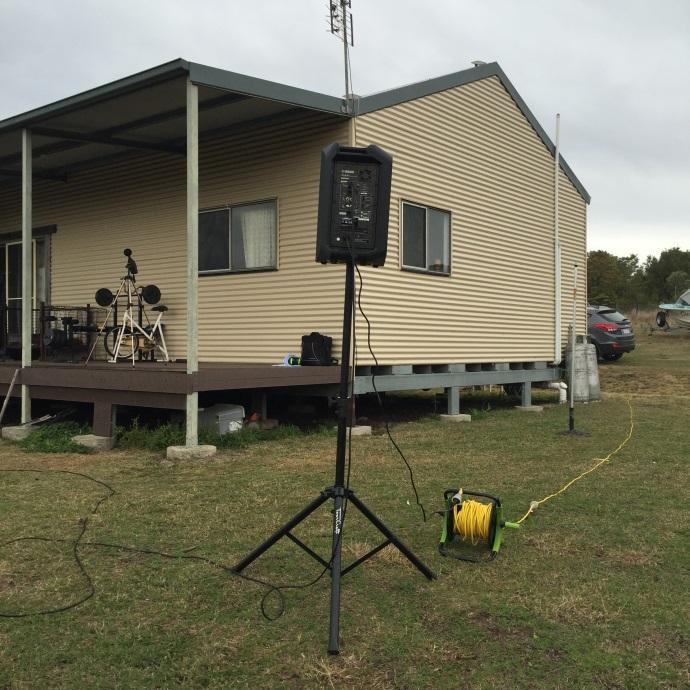
6 Wind Farm Introduction AECOM Australia Pty Ltd (AECOM) was commissioned by AGL Energy Ltd (AGL) to conduct a façade sound insulation assessment at five homestead residences located at the Wind Farm site in Queensland. The testing was conducted in general accordance with international standard ISO :2016 Acoustics Field measurement of sound insulation in buildings and of building elements Part 3: Façade sound insulation. This report provides details of test conducted at five homesteads nearby the wind farm site between Monday 11 July and Wednesday 13 July A description of the tests conducted is presented in the following sections. Full test results are provided in Appendix A to Appendix E. 2.0 Tested Facade Types The following wall types were tested: - House A: Pre-fabricated (fibro) - House B: Metal cladding - House C: Weatherboard - House D: Concrete - House E: Log cabin. The materials listed above are typical materials used for the construction of homestead residences nearby the Wind Farm site. Sound insulation tests were conducted under the following configurations: - Window fully closed - Window partially open (10cm open) - Window fully open. Windows were tested in the partially open window scenario as this reflects a common mode of providing ventilation to a space. 3.0 Sound Insulation Test Details 3.1 Instrumentation A Bruel and Kjaer 2250 sound level meter (serial ) was used to measure the sound levels. The instrument was calibrated in the field with a RION NC-74 Class 1 (serial ) field calibrator before, during and after each measurement set. No calibration drifts in excess of 0.5 db were measured. As such, all measurements are valid, as per ISO The Sound Level Meter (SLM) used for measuring sound pressure levels, including microphone and field calibrator met the requirements for a Class 1 instrument according to IEC Electroacoustics Sound Level Meters Part 1: Specifications. The SLM and the acoustic calibrator had a valid calibration certificate from a National Testing Authorities Association (NATA) accredit laboratory at the time of testing. The instruments had been calibrated by the NATA laboratory within one year prior to the time of testing. Copies of the NATA calibration certificates are provided in Appendix F. A NTI Minirator MR-PRO (serial G2P-RACSV-G0) signal generator was used to feed a Pink Noise signal to a YAMAHA DXR10 (serial EEVP01248) loudspeaker mounted on a tripod. The speaker output level was adjusted to a sound pressure level of approximately 110 db(linear) at 1 metre in front of the loudspeaker.
7 Wind Farm Measurement Frequency Range As per ISO :2016, the acoustic quantities were measured using one-third octave filters for at least the following centre frequencies, in hertz (Hz): - 100, 125, 160, 200, 250, 315, 400, 500, 630, 800, 1000, 1250, 160, 2000, 2500, 3150 Measurement of additional information in the low- and high-frequency ranges is optional, in accordance with ISO :2016. Additional information in the low-frequency and high frequency ranges in hertz was also obtained using the below 1/3 octave filters: - Low frequency: 50, 63, 80 - High frequency: 4000, It is noted that the values below 100 Hz presented in this report may have been affected by the following: - Small volume acoustics conducive to modal behaviour, affecting measurements of reverberation time at low frequencies. It is noted that the reverberation time at the 50 Hz 1/3 octave band could not be measured at all residences. As such, the value had to be extrapolated - Mechanical noises inside some spaces and/or windy conditions affecting background noise. 3.3 Measurement Procedure The following measurement procedure was followed: 1. The room dimensions were measured with a laser range finder and tape measure 2. The loudspeaker was placed at a minimum distance (D) at least 5 m from the centre of the measured room facade, at an angle of 45 ± 5 3. The loudspeaker level was adjusted to generate a pink noise signal at approximately 110 db (linear) at 1m 4. The noise level was measured outside the tested façade whilst the speaker was generating the pink noise signal, using the following two methods: a. The SLM microphone was attached to the tested façade surface. The microphone was placed with its axis parallel to the plane of the façade and directed upwards, with a distance between the test specimen and the centre of the microphone diaphragm <10mm. A hemispherical wind shield was applied to the microphone An averaging time of at least 20 seconds was used per measurement sample. A minimum of five measurements were conducted and the overall sound level difference between measurement positions was generally 2 db or less b. Microphone mounted on a tripod, at a fixed location 2 m in front of the tested façade, at 1.5 m above finished floor level. A spherical wind shield was applied to the microphone 5. The noise level was measured inside the tested room at minimum five positions separated by a minimum 0.7 m and at a minimum 0.5 m distance from the walls to determine the average sound level in the receiving room with the loudspeaker in operation. Where possible, the instrument was positioned such that no two microphone positions were in the same plane relative to the room boundaries and they were not in a regular grid 6. The background noise level was measured inside the tested room whilst the loudspeaker was OFF. An averaging time of at least 30 seconds was used 7. The reverberation time was measured using the interrupted noise method. A pink noise signal was fed to the loudspeaker placed inside the room and the energy decay was recorded by the instrument whilst the pink noise signal was turned OFF. A minimum six measurements (sound decays) were recorded at either three fixed microphone positions and two measurements at each position, or six fixed microphone positions and one measurement at each position, located at a distance greater than 1 m from the loudspeaker
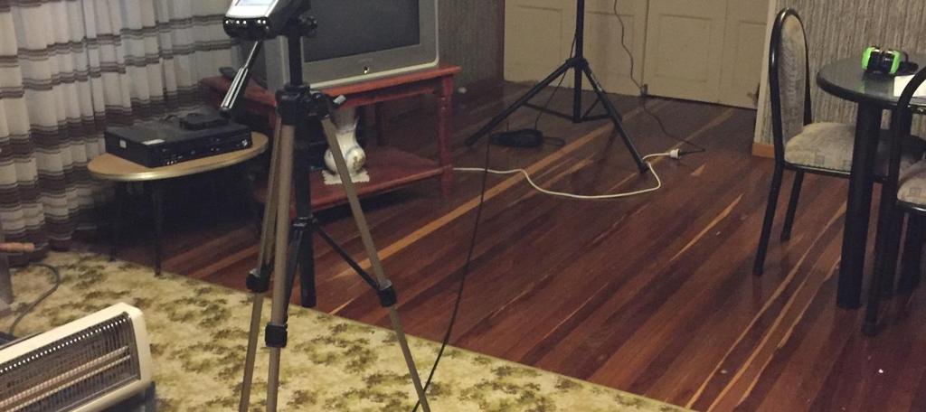
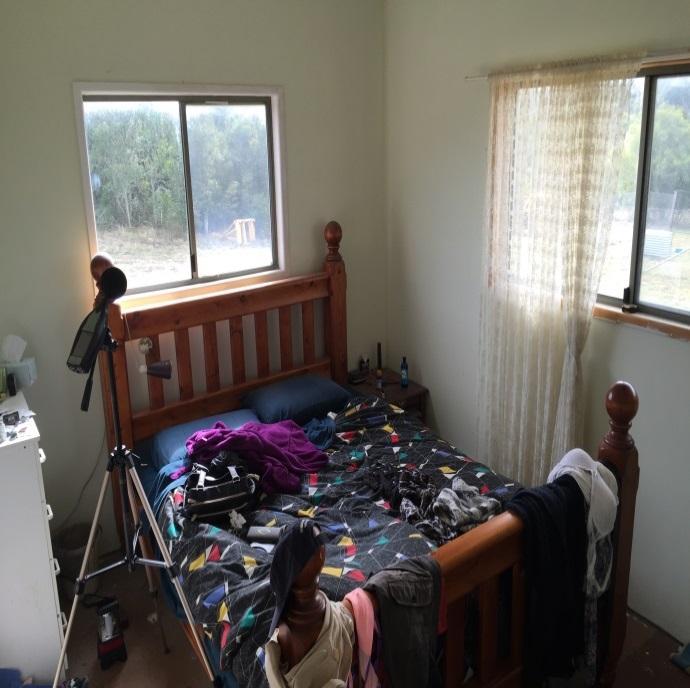
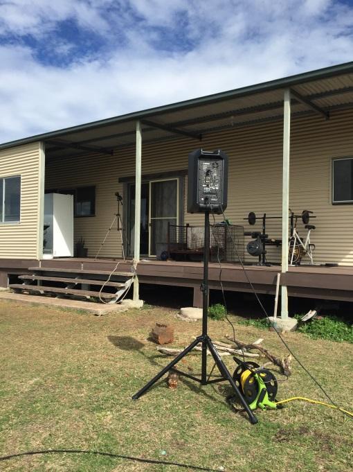
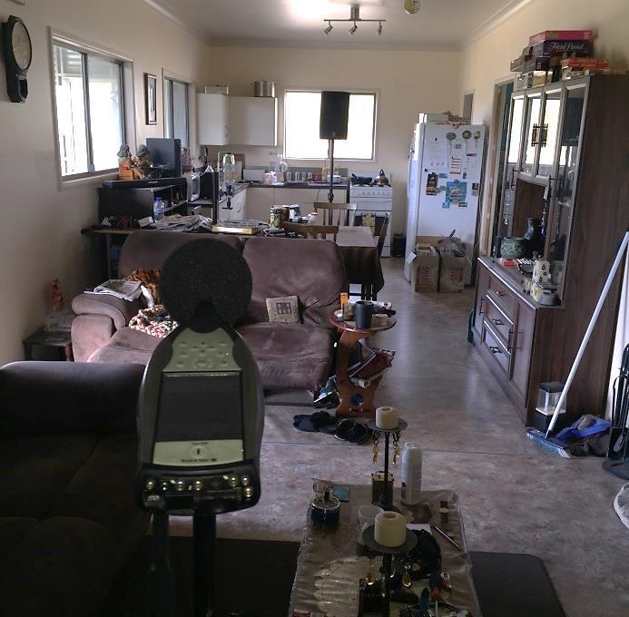
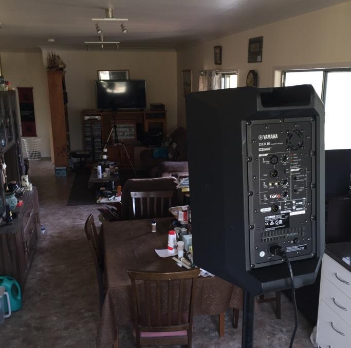
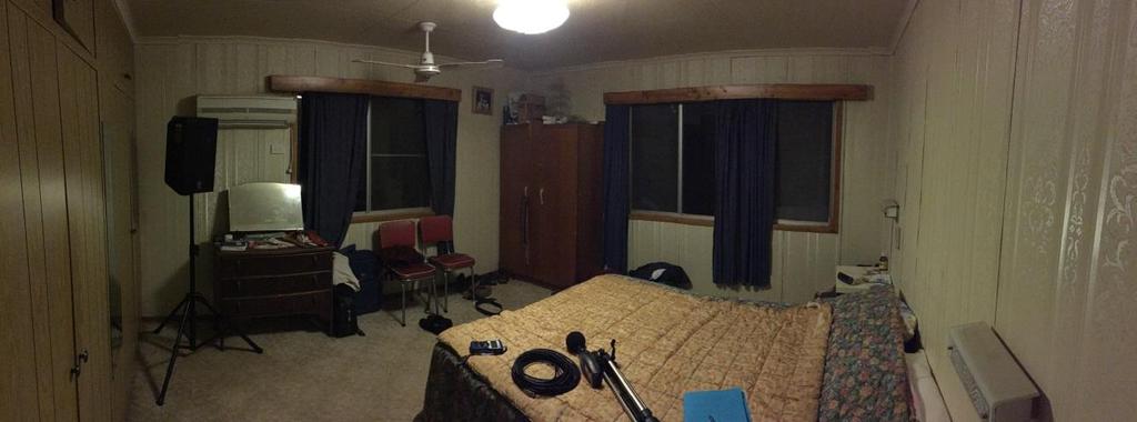
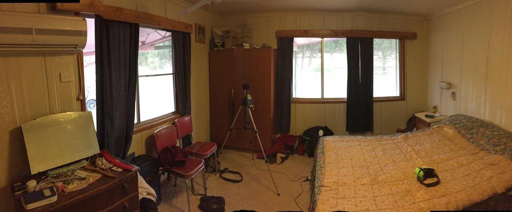
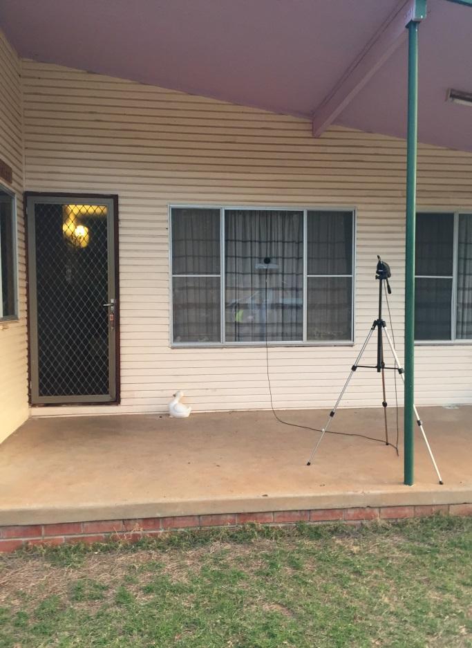
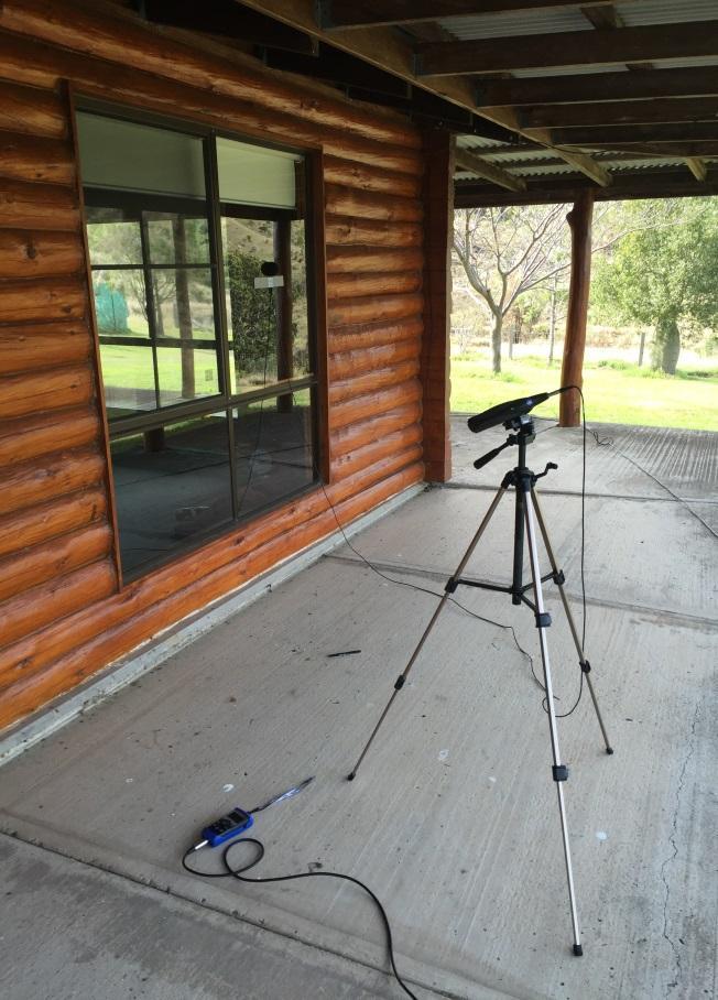
8 Wind Farm 3 The BK2250 sound level meter reverberation time module was used to record the sound decays and automatically calculate the averaged reverberation time in 1/3 octave bands. This module implements the requirements from ISO : Acoustics Measurement of room acoustic parameters Part 2: Reverberation time in ordinary rooms for the calculation of reverberation time indexes, as specified by the instrument manufacturer. The information obtained during measurements was combined using the formulae in ISO to obtain the following sound insulation indexes: - R 45 (Apparent sound reduction index): Measure of the sound insulation of a building element when the sound source is a loudspeaker at an angle of 45 and the outside microphone is on the test surface - D ls,2m (Level difference): Level difference between the sound level measured at 2m from the façade and the internal sound level - D ls,2m,nt (Standardized level difference): Level difference between the sound level measured at 2 m from the façade and the internal sound level that is standardised to a reference value of reverberation time in the receiving room of 0.5 seconds. - D ls,2m,n (Normalised level difference): Level difference between the sound level measured at 2 m from the façade and the internal sound level that is normalised to a reference value of the absorption area in the receiving room of 10 m 2. Example test setup photos are shown in Figure 1 to Figure 4. For practical purposes, the deviations from the standard listed in Table 1 were adopted: Table 1 Deviation from standard ISO specification Loudspeaker placed on the ground Omnidirectional source for reverberation measurement Reverberation measurement at all standardized 1/3 octave frequency bands Deviation from ISO adopted Loudspeaker mounted on a tripod with axis at approximately 1.8 m Standard loudspeaker for reverberation measurement Extrapolation of reverberation value at 50 Hz 1/3 octave band at some residences Implication A loudspeaker on tripod allows for more homogeneous sound radiation to the façade and is not expected to significantly influence the measurement results The loudspeaker used for the test has wide horizontal and vertical radiation, therefore sufficiently excited the room to accurately measure reverberation time The reverberation values at 50 Hz could not be measured by the instrument because the recorded decay did not meet the requirements from ISO Thus they had to be extrapolated. This is expected to be due to modal behaviour of small rooms and/or high background noise; however, the extrapolated values are typical of reverberation time inside small rooms and the extrapolation has as a negligible effect in estimating the overall internal wind farm noise levels


9 Wind Farm 4 Figure 1 Example instrument microphone attached to the tested façade


10 Wind Farm 5 Instrument microphone Loudspeaker Figure 2 Example instrument microphone placed at 2m from façade and at 1.5m above finished floor level


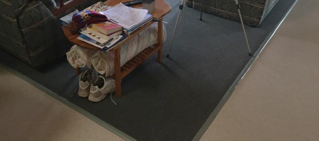
11 Wind Farm 6 Figure 3 Example background noise measurement setup

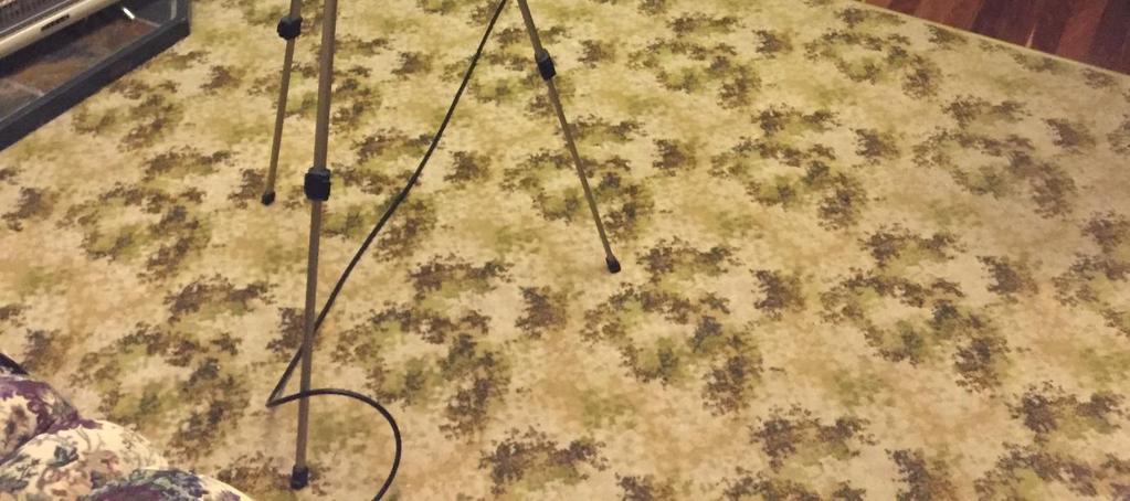
12 Wind Farm 7 Figure 4 Example reverberation time measurement setup
13 Wind Farm Façade Sound Insulation Test Results Table 2 to Table 4 present results for the overall measured façade sound insulation ratings. Test results presenting measured values for the individual 1/3 octave frequency bands are presented in Appendix A to Appendix E. Table 2 Overall measured sound insulation values (windows closed) Overall façade sound insulation, db House Façade construction R '45 D ls,2m D ls,2m,nt D ls,2m,n House A - Bedroom Pre-fabricated (Fibro) House B - Bedroom Steel cladding House B - Living room Steel cladding House C - Bedroom Weatherboard House C - Living room Weatherboard House D - Living room Concrete House E - Living room Log Table 3 Overall measured sound insulation values (1 window 10cm open) Overall façade sound insulation, db House Façade construction R '45 D ls,2m D ls,2m,nt D ls,2m,n House A - Bedroom Pre-fabricated (Fibro) House B - Bedroom Steel cladding House B - Living room Steel cladding House C - Bedroom Weatherboard House C - Living room Weatherboard House D - Living room Concrete House E - Living room Log Table 4 Overall measured sound insulation values (window fully open) House Façade construction Overall façade sound insulation, db R '45 D ls,2m D ls,2m,nt D ls,2m,n House A Bedroom* Pre-fabricated (Fibro) 13 (12) 12 (10) 10 (9) 9 (8) House B - Bedroom Steel cladding House B - Living room Steel cladding House C - Bedroom Weatherboard House C - Living room Weatherboard House D - Living room Concrete House E - Living room Log *: Two tests with open windows were conducted. Test one was conducted with one open window and Test 2 was conducted with two open windows (results for Test 2 in brackets). The second test was conducted on the residence owner s request.
14 Wind Farm Wind Farm Noise Reduction and Internal Noise Levels The measured sound reduction of the different tested building facades allows for the internal wind farm noise level to be estimated. The internal wind farm noise levels can be estimated by subtracting the measured D ls,2m to predicted external noise levels at the residences in 1/3 octave bands. The resulting 1/3 octave noise levels can then be logarithmically summed to obtain the overall forecast level (db(a)) from the potential wind farm inside the tested spaces. 5.1 Estimated Internal Wind Farm Noise Levels A calculation was conducted to estimate the wind farm noise levels inside the tested spaces with the windows open. The calculation used the measured sound insulation results presented in this report and noise predictions as 1/3 octave noise levels outside the spaces. The external noise levels were obtained using the noise model developed as part of the Wind Farm Noise and Vibration Impact Assessment, detailed in document AC-RP-0001-Rev2. The internal noise levels were estimated by subtracting the measured D ls,2m to the predicted external noise levels at the residences, in 1/3 octave bands. The resulting 1/3 octave noise levels were then logarithmically summed to obtain the overall db(a) value inside the tested space. No correction (e.g. normalization or standardisation) has been made for measured reverberation time levels. Results from this calculation are presented in column 3 and column 4 in Table 5. It was found that when the tested spaces have the windows open, the expected wind farm noise attenuation is 8-13 db(a). It is noted that the results presented in Table 5 are provided for information purposes only as the calculation of indoor wind farm noise is not prescribed in ISO :2016 and the noise impacts of wind farms in Queensland are to be assessed outdoors, as prescribed in the Queensland Wind Farm State Code and Planning Guideline (Department of Infrastructure, Local Government and Planning, 2016), effective 22 July Table 5 Estimated wind farm noise attenuation and internal noise levels with open windows Receptor House A Bedroom House B Bedroom House B Living room House C Bedroom House C Living room House D Living room House E Living room House construction Pre-fabricated (fibro) Forecast external wind farm noise level, db(a) Estimated internal wind farm noise level (forecast external level minus D ls,2m) with open window, db(a) Steel cladding Steel cladding Weatherboard Weatherboard Concrete Log Estimated overall wind farm noise reduction of façade with open window, db(a)
15 Wind Farm Internal Ambient Noise Levels Table 6 provides results of measured ambient noise levels measured inside the tested spaces, prior to construction of the wind farm. Where possible, noise peaks resulting from human activity inside and outside the dwellings were filtered, but some contamination remained, as noted in the table. Audible sources of noise inside the dwellings include wildlife, wind and rain, and internal sources include refrigerators and other white goods, clocks, generators, and human activities. Table 6 Measured internal ambient noise levels Receptor House A Bedroom House B Bedroom House B Living room House C Bedroom House C Living room House D Living room House E Living room House construction Pre-fabricated (fibro) *: Measurement contaminated by human noise. Internal noise level with windows open, L Aeq,T, db(a) Steel cladding 41 41* Steel cladding Weatherboard 31 34* Weatherboard 30 31* Concrete Not measured 33 Log Not measured 31 Internal noise level with windows closed, L Aeq,T, db(a) 7.0 Conclusion AECOM conducted a façade sound insulation assessment at five homestead residences located adjacent to the proposed wind farm site, between Monday 11 July 2016 and Wednesday 13 July The testing was conducted in accordance with international standard ISO :2016 Acoustics Field measurement of sound insulation in buildings and of building elements Part 3: Façade sound insulation. The methodology and results of ISO :2016 sound insulation indices are presented in this report. In addition, an estimation of internal wind farm noise levels was conducted. It was found that when the windows are open at the tested spaces, the expected internal wind farm noise levels range between db(a) with a wind farm noise attenuation of 8-13 db(a) for the tested spaces.
16 Wind Farm Appendix A House A Sound Insulation Test Results
17 Wind Farm Appendix A House A Sound Insulation Test Results Main Bedroom House A Test Details Main bedroom Date: Operator: Rodrigo O. Time: 1:45pm start Company: AECOM Australia Pty Ltd Sound level meter Model & Serial: Bruel and Kjaer 2250, serial Acoustic calibrator Model & Serial: RION NC-74, serial Signal Gen Model & Serial: Room name and type: NTI Minirator MR-PRO, serial G2P-RACSV-G0 Main bedroom Room dimensions, internal: 4m x 4m x 2.4m Room volume, m 3 : 38 Tested façade area, m 2 : 19 Window Type: sliding window Window Dimensions (m): Exposed Façade Dimensions (m 2 ): Reverberation time (overall): Façade construction: Test Standard: Glass thickness: 3mm approx. SLM Calibration Start: SLM Calibration End: Loudspeaker Model & Serial: Window condition: Two windows 1.9m x 1.2m, one window per façade 2 walls: 4m x 2.4m each T20: 0.34 sec T30: 0.33 sec Pre-fabricated (fibro) Tests conducted: YAMAHA DXR10, serial EEVP01248 Old. One portable AC unit installed in one window 1. Windows closed 2. 1 window 10cm open 3. 1 window open 4. 2 windows open ISO :2016 Acoustics - Field Measurement of sound insulation in buildings and of building elements - Part 3: Façade sound insulation GLOSSARY R 45 (Apparent sound reduction index) Measure of the sound insulation of a building element when the sound source is a loudspeaker at an angle of 45 and the outside microphone is on the test surface D ls,2m (Level difference) Level difference between the sound level measured at 2m from the façade and the internal sound level. D ls,2m,nt (Standardized level difference) Level difference between the sound level measured at 2m from the façade and the internal sound level that is standardized to a reference value of reverberation time in the receiving room of 0.5 seconds. D ls,2m,n (Normalised level difference) Level difference between the sound level measured at 2m from the façade and the internal sound level that is normalized to a reference value of the absorption area in the receiving room of 10m 2. T20, T30 (Reverberation time) Reverberation time measured by extrapolation of the sound energy decay time measured for the first 20 db and 30 db, respectively, to a 60 db decay time.
18 Wind Farm Test 1 Main bedroom: All windows closed Façade sound insulation, db Overall value (all frequencies) R 45 D ls,2m D ls,2m,nt D ls,2m,n Hz 10* 7 8* 7* 63Hz Hz Hz Hz Hz Hz Hz Hz Hz Hz Hz Hz kHz kHz kHz kHz kHz kHz kHz kHz *: Value calculated using extrapolated value of reverberation time, due to problems measuring reverberation in small volume room
19 Wind Farm Test 2 Main bedroom: One window 10cm open Façade sound insulation, db Overall value (all frequencies) R' 45 D ls,2m D ls,2m,nt D ls,2m,n Hz 11* 9 9* 8* 63Hz Hz Hz Hz Hz Hz Hz Hz Hz Hz Hz Hz kHz kHz kHz kHz kHz kHz kHz kHz *: Value calculated using extrapolated value of reverberation time, due to problems measuring reverberation in small volume room
20 Wind Farm Test 3 Main bedroom: One window open Façade sound insulation, db Overall value (all frequencies) R' 45 D ls,2m D ls,2m,nt D ls,2m,n Hz 11* 9 9* 8* 63Hz Hz Hz Hz Hz Hz Hz Hz Hz Hz Hz Hz kHz kHz kHz kHz kHz kHz kHz kHz *: Value calculated using extrapolated value of reverberation time, due to problems measuring reverberation in small volume room
21 Wind Farm Test 4 Main bedroom: Two windows open Façade sound insulation, db Overall value (all frequencies) R' 45 D ls,2m D ls,2m,nt D ls,2m,n Hz 8* 6 6* 5* 63Hz Hz Hz Hz Hz Hz Hz Hz Hz Hz Hz Hz kHz kHz kHz kHz kHz kHz kHz kHz *: Value calculated using extrapolated value of reverberation time, due to problems measuring reverberation in small volume room


22 Wind Farm Figure A-1: Site photos
23 Wind Farm Appendix B House B Sound Insulation Test Results
24 Wind Farm Appendix B House B Sound Insulation Test Results - Bedroom House B Test Details - Bedroom Date: Operator: Rodrigo O. Time: 9:30am start Company: AECOM Australia Pty Ltd Sound level meter Model & Serial: Bruel and Kjaer 2250, serial Acoustic calibrator Model & Serial: RION NC-74, serial Signal Gen Model & Serial: Room name and type: NTI Minirator MR-PRO, serial G2P-RACSV-G0 Bedroom Room dimensions (internal): 4m x 3m x 2.7m Room volume, m 3 : 32 Tested façade area, m 2 : 19 Window Type: sliding window Window Dimensions (m): Glass thickness: Exposed Façade Dimensions (m 2 ): Wall 1: 4m x 2.7m Wall 2: 3m x 2.7m Reverberation time (overall): Façade construction: Notes: Test Standard: SLM Calibration Start: SLM Calibration End: Loudspeaker Model & Serial: 3 mm approx. Window condition: YAMAHA DXR10, serial EEVP01248 Operable. Good condition. Two windows: 1.7m x 0.9m, 1.2m x 0.9m, one window per façade T20: 0.52 sec T30: 0.66 sec Steel cladding Windy during test Tests conducted: 1. Windows closed 2. 1 window 10cm open 3. 1 window open ISO :2016 Acoustics - Field Measurement of sound insulation in buildings and of building elements - Part 3: Façade sound insulation GLOSSARY R 45 (Apparent sound reduction index) Measure of the sound insulation of a building element when the sound source is a loudspeaker at an angle of 45 and the outside microphone is on the test surface D ls,2m (Level difference) Level difference between the sound level measured at 2m from the façade and the internal sound level. D ls,2m,nt (Standardized level difference) Level difference between the sound level measured at 2m from the façade and the internal sound level that is standardized to a reference value of reverberation time in the receiving room of 0.5 seconds. D ls,2m,n (Normalised level difference) Level difference between the sound level measured at 2m from the façade and the internal sound level that is normalized to a reference value of the absorption area in the receiving room of 10m 2. T20, T30 (Reverberation time) Reverberation time measured by extrapolation of the sound energy decay time measured for the first 20 db and 30 db, respectively, to a 60 db decay time.
25 Wind Farm Note: Sound levels below 100 Hz may have been affected by modal behaviour, low signal to noise ratio and/or high background noise. Test 1 Bedroom: Windows closed Façade sound insulation, db Overall value (all frequencies) R' 45 D ls,2m D ls,2m,nt D ls,2m,n Hz Hz Hz Hz Hz Hz Hz Hz Hz Hz Hz Hz Hz kHz kHz kHz kHz kHz kHz kHz kHz
26 Wind Farm Test 2 Bedroom: One window 10cm open Façade sound insulation, db Overall value (all frequencies) R' 45 D ls,2m D ls,2m,nt D ls,2m,n Hz Hz Hz Hz Hz Hz Hz Hz Hz Hz Hz Hz Hz kHz kHz kHz kHz kHz kHz kHz kHz
27 Wind Farm Test 3 Bedroom: One window open Façade sound insulation, db Overall value (all frequencies) R' 45 D ls,2m D ls,2m,nt D ls,2m,n Hz Hz Hz Hz Hz Hz Hz Hz Hz Hz Hz Hz Hz kHz kHz kHz kHz kHz kHz kHz kHz


28 Wind Farm Figure B-1: Site photos
29 Wind Farm Appendix B House B Sound Insulation Test Results Living Room House B Test Details Living room Date: Operator: Rodrigo O. Time: 11:35am start Company: AECOM Australia Pty Ltd Sound level meter Model & Serial: Bruel and Kjaer 2250, serial Acoustic calibrator Model & Serial: RION NC-74, serial Signal Gen Model & Serial: Room name and type: NTI Minirator MR-PRO, serial G2P-RACSV-G0 Living room Room dimensions: 10.8m x 3.2m x 2.7m Room volume, m 3 : 93 Tested façade area, m 2 : 29 Window Type: sliding window Glass thickness: 3mm approx. SLM Calibration Start: SLM Calibration End: Loudspeaker Model & Serial: Window condition: Window Dimensions (m): Sliding glass door: 1.8m x 2.1m, Window 1: 1.6m x 0.9m Window 2: 1.5m x 0.9m Exposed Façade Dimensions (m 2 ) Reverberation time (overall): Façade construction: Test Standard: 1 wall: 10.8m x 2.7m T20: 0.41 sec T30: 0.45 sec Steel cladding house Tests conducted: YAMAHA DXR10, serial EEVP01248 Operable. Good condition. 1. Windows closed 2. Sliding glass door 10cm open 3. Sliding glass door 10cm open ISO :2016 Acoustics - Field Measurement of sound insulation in buildings and of building elements - Part 3: Façade sound insulation GLOSSARY R 45 (Apparent sound reduction index) Measure of the sound insulation of a building element when the sound source is a loudspeaker at an angle of 45 and the outside microphone is on the test surface D ls,2m (Level difference) Level difference between the sound level measured at 2m from the façade and the internal sound level. D ls,2m,nt (Standardized level difference) Level difference between the sound level measured at 2m from the façade and the internal sound level that is standardized to a reference value of reverberation time in the receiving room of 0.5 seconds. D ls,2m,n (Normalised level difference) Level difference between the sound level measured at 2m from the façade and the internal sound level that is normalized to a reference value of thye absorption area in the receiving room of 10m 2. T20, T30 (Reverberation time) Reverberation time measured by extrapolation of the sound energy decay time measured for the first 20 db and 30 db, respectively, to a 60 db decay time.
30 Wind Farm Note: Sound levels below 100 Hz may have been affected by modal behaviour, low signal to noise ratio and/or high background noise. Test 1 Living room: Windows closed Façade sound insulation, db Overall value (all frequencies) R' 45 D ls,2m D ls,2m,nt D ls,2m,n Hz N.A. 63Hz Hz Hz Hz Hz Hz Hz Hz Hz Hz Hz Hz kHz kHz kHz kHz kHz kHz kHz kHz
31 Wind Farm Test 2 Living room: Sliding door 10cm open Façade sound insulation, db Overall value (all frequencies) R' 45 D ls,2m D ls,2m,nt D ls,2m,n Hz Hz Hz Hz Hz Hz Hz Hz Hz Hz Hz Hz Hz kHz kHz kHz kHz kHz kHz kHz kHz
32 Wind Farm Test 3 Bedroom: Sliding door open Façade sound insulation, db Overall value (all frequencies) R' 45 D ls,2m D ls,2m,nt D ls,2m,n Hz Hz Hz Hz Hz Hz Hz Hz Hz Hz Hz Hz Hz kHz kHz kHz kHz kHz kHz kHz kHz


33 Wind Farm Figure B-2: Site photos
34 Wind Farm Appendix C House C Sound Insulation Test Results
35 Wind Farm C-1 Appendix C House C Sound Insulation Test Results Main Bedroom House C Test Details Bedroom Date: Operator: Rodrigo O. Time: 04:05pm start Company: AECOM Australia Pty Ltd Sound level meter Model & Serial: Bruel and Kjaer 2250, serial Acoustic calibrator Model & Serial: RION NC-74, serial Signal Gen Model & Serial: Room name and type: NTI Minirator MR-PRO, serial G2P-RACSV-G0 Main bedroom Room dimensions: 4.2m x 3.9m x 2.4m Room volume, m 3 : 39 Tested façade area, m 2 : 19 Window Type: sliding window Glass thickness: 3mm approx. Window Dimensions (m): Window 1: 2.1m x 1.2m Window 2: 1.5m x 1.2m Exposed Façade Dimensions (m 2 ) Wall 1: 4.2m x 2.4m Wall 2: 3.9m x 2.4m Reverberation time (overall): Façade construction: Test Standard: T20: 0.31 sec T30: 0.34 sec Weatherboard SLM Calibration Start: SLM Calibration End: Loudspeaker Model & Serial: Tests conducted: Window condition: YAMAHA DXR10, serial EEVP01248 Operable. Good condition. 1. Windows closed 2. 1 window 10cm open 3. 1 window open ISO :2016 Acoustics - Field Measurement of sound insulation in buildings and of building elements - Part 3: Façade sound insulation GLOSSARY R 45 (Apparent sound reduction index) Measure of the sound insulation of a building element when the sound source is a loudspeaker at an angle of 45 and the outside microphone is on the test surface D ls,2m (Level difference) Level difference between the sound level measured at 2m from the façade and the internal sound level. D ls,2m,nt (Standardized level difference) Level difference between the sound level measured at 2m from the façade and the internal sound level that is standardized to a reference value of reverberation time in the receiving room of 0.5 seconds. D ls,2m,n (Normalised level difference) Level difference between the sound level measured at 2m from the façade and the internal sound level that is normalized to a reference value of the absorption area in the receiving room of 10m 2. T20, T30 (Reverberation time) Reverberation time measured by extrapolation of the sound energy decay time measured for the first 20 db and 30 db, respectively, to a 60 db decay time.
36 Wind Farm C-2 Note: Sound levels below 100 Hz may have been affected by modal behaviour, low signal to noise ratio and/or high background noise. Test 1 Main bedroom: Windows closed Façade sound insulation, db Overall value (all frequencies) R' 45 D ls,2m D ls,2m,nt D ls,2m,n Hz Hz Hz Hz Hz Hz Hz Hz Hz Hz Hz Hz Hz kHz kHz kHz kHz kHz kHz kHz kHz
37 Wind Farm C-3 Test 2 Main bedroom: 1 windows 10cm open Façade sound insulation, db Overall value (all frequencies) R' 45 D ls,2m D ls,2m,nt D ls,2m,n Hz Hz Hz Hz Hz Hz Hz Hz Hz Hz Hz Hz Hz kHz kHz kHz kHz kHz kHz kHz kHz
38 Wind Farm C-4 Test 3 Main bedroom: 1 window open Façade sound insulation, db Overall value (all frequencies) R' 45 D ls,2m D ls,2m,nt D ls,2m,n Hz Hz Hz Hz Hz Hz Hz Hz Hz Hz Hz Hz Hz kHz kHz kHz kHz kHz kHz kHz kHz


39 Wind Farm C-5 Figure C-1: Site photos
40 Wind Farm C-6 Appendix C House C Sound Insulation Test Results Living Room House C Test Details Living Room Date: Operator: Rodrigo O. Time: 04:05pm start Company: AECOM Australia Pty Ltd Sound level meter Model & Serial: Bruel and Kjaer 2250, serial Acoustic calibrator Model & Serial: RION NC-74, serial Signal Gen Model & Serial: Room name and type: Room dimensions: Room volume, m 3 : Tested façade area, m 2 : 17 Window Type: sliding window NTI Minirator MR-PRO, serial G2P-RACSV-G0 Living room SLM Calibration Start: SLM Calibration End: Loudspeaker Model & Serial: 7.2m x 5m x 2.4m (gross dimensions) YAMAHA DXR10, serial EEVP (includes hallways and excludes entertainment room, which access doors were kept closed during the test). Glass thickness: 3mm approx. Window condition: Old but operable Window Dimensions (m): Window 1: 2.1m x 1.5m - Window 2: 2.1m x 1.5m - Door: 2.0m x 0.8m Exposed Façade Dimensions (m 2 ) 7.2m x 2.4m Tests conducted: Reverberation time (overall): Façade construction: Test Standard: T20: 0.53 sec T30: 0.52 sec Weatherboard 1. Windows closed 2. 1 window 10cm open 3. Windows open ISO :2016 Acoustics - Field Measurement of sound insulation in buildings and of building elements - Part 3: Façade sound insulation GLOSSARY R 45 (Apparent sound reduction index) Measure of the sound insulation of a building element when the sound source is a loudspeaker at an angle of 45 and the outside microphone is on the test surface D ls,2m (Level difference) Level difference between the sound level measured at 2m from the façade and the internal sound level. D ls,2m,nt (Standardized level difference) Level difference between the sound level measured at 2m from the façade and the internal sound level that is standardized to a reference value of reverberation time in the receiving room of 0.5 seconds. D ls,2m,n (Normalised level difference) Level difference between the sound level measured at 2m from the façade and the internal sound level that is normalized to a reference value of the absorption area in the receiving room of 10m 2. T20, T30 (Reverberation time) Reverberation time measured by extrapolation of the sound energy decay time measured for the first 20 db and 30 db, respectively, to a 60 db decay time.
41 Wind Farm C-7 Note: Sound levels below 100 Hz may have been affected by modal behaviour, low signal to noise ratio and/or high background noise. Test 1 Living room: Windows closed Façade sound insulation, db Overall value (all frequencies) R' 45 D ls,2m D ls,2m,nt D ls,2m,n Hz Hz Hz Hz Hz Hz Hz Hz Hz Hz Hz Hz Hz kHz kHz kHz kHz kHz kHz kHz kHz
42 Wind Farm C-8 Test 2 Living room: 1 window 10cm open Façade sound insulation, db Overall value (all frequencies) R' 45 D ls,2m D ls,2m,nt D ls,2m,n Hz N.A. 1 3 N.A. 63Hz Hz Hz Hz Hz Hz Hz Hz Hz Hz Hz Hz kHz kHz kHz kHz kHz kHz kHz kHz N.A: Insufficient outdoor-to-indoor sound level difference at 50Hz with window partially open for value to be calculated.
43 Wind Farm C-9 Test 3 Living room: 2 windows open Façade sound insulation, db Overall value (all frequencies) R' 45 D ls,2m D ls,2m,nt D ls,2m,n Hz Hz Hz Hz Hz Hz Hz Hz Hz Hz Hz Hz Hz kHz kHz kHz kHz kHz kHz kHz kHz


44 Wind Farm C-10 Figure C-2: Site photos
45 Wind Farm Appendix D House D Sound Insulation Test Results
46 Wind Farm Appendix D House D Sound Insulation Test Results Living Room House D Test Details Living Room Date: Operator: Rodrigo O. Time: 09:50am start Company: AECOM Australia Pty Ltd Sound level meter Model & Serial: Acoustic calibrator Model & Serial: Signal Gen Model & Serial: Room name and type: Room dimensions: Room volume, m 3 : Tested façade area, m 2 : Bruel and Kjaer 2250, serial RION NC-74, serial NTI Minirator MR-PRO, serial G2P-RACSV-G0 Living room SLM Calibration Start: SLM Calibration End: Loudspeaker Model & Serial: 8.1m x 4.7m x 2.6m (gross room dimensions) YAMAHA DXR10, serial EEVP m 3 (includes hallway and excludes kitchen, which is separated from living room by hallway walls). 21 m 2 (8.1m x 2.6m) Window Type: sliding window Glass thickness: 6mm approx. Window condition: Good Window Dimensions (m): Exposed Façade Dimensions (m 2 ) Façade construction: Reverberation time (overall): Notes: Test Standard: Window 1: 2.1m x 2.0m - Window 2: 2.1m x 2.0m - Door: Not taken 7.2m x 2.4m Tests conducted: Concrete T20: 0.58 sec T30: 0.61 sec Very windy conditions during test 1. Windows closed 2. 1 window 10cm open 3. Windows open ISO :2016 Acoustics - Field Measurement of sound insulation in buildings and of building elements - Part 3: Façade sound insulation GLOSSARY R 45 (Apparent sound reduction index) Measure of the sound insulation of a building element when the sound source is a loudspeaker at an angle of 45 and the outside microphone is on the test surface D ls,2m (Level difference) Level difference between the sound level measured at 2m from the façade and the internal sound level. D ls,2m,nt (Standardized level difference) Level difference between the sound level measured at 2m from the façade and the internal sound level that is standardized to a reference value of reverberation time in the receiving room of 0.5 seconds. D ls,2m,n (Normalised level difference) Level difference between the sound level measured at 2m from the façade and the internal sound level that is normalized to a reference value of the absorption area in the receiving room of 10m 2. T20, T30 (Reverberation time) Reverberation time measured by extrapolation of the sound energy decay time measured for the first 20 db and 30 db, respectively, to a 60 db decay time.
47 Wind Farm Note: Sound levels below 100 Hz may have been affected by modal behaviour, low signal to noise ratio and/or high background noise. Test 1 Living room: Windows closed Façade sound insulation, db *: Value obtained using extrapolated value of reverberation time Overall value (all frequencies) R' 45 D ls,2m D ls,2m,nt D ls,2m,n Hz 9* 13 14* 8* 63Hz Hz Hz Hz Hz Hz Hz Hz Hz Hz Hz Hz kHz kHz kHz kHz kHz kHz kHz kHz
48 Wind Farm Test 2 Living room: 1 window 10cm open Façade sound insulation, db *: Value obtained using extrapolated value of reverberation time. Overall value (all frequencies) R' 45 D ls,2m D ls,2m,nt D ls,2m,n Hz 13* 17 18* 12* 63Hz Hz Hz Hz Hz Hz Hz Hz Hz Hz Hz Hz kHz kHz kHz kHz kHz kHz kHz kHz
49 Wind Farm Test 3 Living room: 2 windows open Façade sound insulation, db *: Value obtained using extrapolated value of reverberation time. Overall value (all frequencies) R' 45 D ls,2m D ls,2m,nt D ls,2m,n Hz 9* 13 14* 8* 63Hz Hz Hz Hz Hz Hz Hz Hz Hz Hz Hz Hz kHz kHz kHz kHz kHz kHz kHz kHz


50 Wind Farm Figure D-1: Site photos
51 Wind Farm Appendix E House E Sound Insulation Test Results
52 Wind Farm E-1 Appendix E House E Sound Insulation Test Results Living Room House E Test Details Living Room Date: Operator: Rodrigo O. Time: 1:30pm start Company: AECOM Australia Pty Ltd Sound level meter Model & Serial: Bruel and Kjaer 2250, serial Acoustic calibrator Model & Serial: RION NC-74, serial Signal Gen Model & Serial: Room name and type: Room dimensions (internal): Room volume, m 3 : NTI Minirator MR-PRO, serial G2P-RACSV-G0 Living room Tested façade area, m 2 : 44 m 2 Window Type: sliding windows SLM Calibration Start: SLM Calibration End: Loudspeaker Model & Serial: YAMAHA DXR10, serial EEVP m x 9.6m x 2.7m (gross room dimensions). Pitched roof. Building height 2.7m at shoulder and 3.9m at ridge 212 m 3 (includes hallways). Glass thickness: 3mm approx. Window condition: Good condition Window Dimensions (m): Window 1: 1.8m x 1.8m - Window 2: 1.8m x 1.8m - Window 3: 1.8m x 1.2m Sliding glass Door: 1.9m x 2.2m Exposed Façade Dimensions (m 2 ) Wall 1: 6.7m x 2.7m Wall 2: 9.6m x 2.6m Façade construction: Reverberation time (overall): Notes: Log cabin T sec T sec Tests conducted: Very windy conditions during test 1. Windows closed 2. 1 window 10cm open (wall 1) 3. 2 Windows open (wall1 and 2) GLOSSARY R 45 (Apparent sound reduction index) Measure of the sound insulation of a building element when the sound source is a loudspeaker at an angle of 45 and the outside microphone is on the test surface D ls,2m (Level difference) Level difference between the sound level measured at 2m from the façade and the internal sound level. D ls,2m,nt (Standardized level difference) Level difference between the sound level measured at 2m from the façade and the internal sound level that is standardized to a reference value of reverberation time in the receiving room of 0.5 seconds. D ls,2m,n (Normalised level difference) Level difference between the sound level measured at 2m from the façade and the internal sound level that is normalized to a reference value of thye absorption area in the receiving room of 10m 2. T20, T30 (Reverberation time) Reverberation time measured by extrapolation of the sound energy decay time measured for the first 20 db and 30 db, respectively, to a 60 db decay time.
53 Wind Farm E-2 Test 1 Living room: Windows closed Façade sound insulation, db Overall value (all frequencies) R' 45 D ls,2m D ls,2m,nt D ls,2m,n Hz Hz Hz Hz Hz Hz Hz Hz Hz Hz Hz Hz Hz kHz kHz kHz kHz kHz kHz kHz kHz
54 Wind Farm E-3 Test 2 Living room: 1 window 10cm open Façade sound insulation, db Overall value (all frequencies) R' 45 D ls,2m D ls,2m,nt D ls,2m,n Hz Hz Hz Hz Hz Hz Hz Hz Hz Hz Hz Hz Hz kHz kHz kHz kHz kHz kHz kHz kHz
55 Wind Farm E-4 Test 3 Living room: 2 windows open Façade sound insulation, db Overall value (all frequencies) R' 45 D ls,2m D ls,2m,nt D ls,2m,n Hz Hz Hz Hz Hz Hz Hz Hz Hz Hz Hz Hz Hz kHz kHz kHz kHz kHz kHz kHz kHz


56 Wind Farm E-5 Figure E-1: Site photos
57 Wind Farm Appendix F Calibration Certificates
58 Wind Farm F-1 Appendix F Bruel & Kjaer SLM Calibration Certificate

59 Wind Farm F-2 Appendix F RION NC-74 Calibrator Calibration Certificate
Statement Of Results For Sound Transmission Loss Tests Performed By Acoustics Laboratory At RMIT University On Behalf Of Polyphen.
 22/5/2007 Statement Number RMIT University, Department of Applied Physics, GPO Box 2476V Melbourne, Victoria 3001 Australia Attn: Ingmar Quist Polyphen Level 12, 45 William Street Melbourne, Victoria 3000
REPORT issued by an Accredited Testing Laboratory
 issued by an Accredited Testing Laboratory Contact person Fredrik Öberg 2017-04-25 7P02435 1 (7) Building Technology +46 10 516 56 06 fredrik.oberg@ri.se Essve Produkter AB Fredrik Sivertsson Box 7091
Sound Insulation Reporter
 Sound Insulation Reporter for XL2 Sound Level Meter V1.28.00 www.nti-audio.com Jul 18, Page 1 / 58 Index 1. Introduction...3 2. Standards...4 3. My First Steps...5 Software Installation... 5 Additional
Delta Series Single Stage Louvres LOUVRES
 Louvreclad s Delta Series is a high-strength rollformed perforated high tensile steel louvre that ensures high security while allowing good ventilation. Alternatively, Delta Series can be specified without
MANAGING NOISE IMPACTS IN BRISBANE S FORTITUDE VALLEY ENTERTAINMENT PRECINCT
 MANAGING NOISE IMPACTS IN BRISBANE S FORTITUDE VALLEY ENTERTAINMENT PRECINCT Frank D. Henry (1), Ken C. S. Mackenzie (1) (1) Brisbane City Council, Queensland Abstract The construction of residential apartments
What is the minimum sound pressure level iphone or ipad can measure? What is the maximum sound pressure level iphone or ipad can measure?
 Technical Note 1701 i437l- Frequent Asked Questions Question 1 : What are the advantages of MicW i437l? Answer 1 : The i437l is a digital microphone connected to iphone Lightning connector. It has flat
Is INTERNATIONAL STANDARD. Acoustics - Measurement of the in sifu sound attenuation of a removable screen
 INTERNATIONAL STANDARD Is0 11821 First edition 1997-04-O 1 Acoustics - Measurement of the in sifu sound attenuation of a removable screen Acoustique - Mesurage de I atthuation acoustique in situ d un &ran
THE EFFECT OF PERFORMANCE STAGES ON SUBWOOFER POLAR AND FREQUENCY RESPONSES
 THE EFFECT OF PERFORMANCE STAGES ON SUBWOOFER POLAR AND FREQUENCY RESPONSES AJ Hill Department of Electronics, Computing & Mathematics, University of Derby, UK J Paul Department of Electronics, Computing
Comparison of Low Frequency Sound Insulation Field Measurement Methods
 of Low Frequency Sound Insulation Field Measurement Methods Sandy Marshall, Doheon Lee and Densil Cabrera Faculty of Architecture, University of Sydney, NSW 2006, Australia A paper previously presented
2.0 SOUND SOURCES AT PINE RIDGES INLAND CLAMSHELL OPERATION AREA
 DATE September 25, 2012 PROJECT No. 11-1422-0046 TO Derek Holmes BURNCO Rock Products Ltd CC Kim Titus, BURNCO Rock Products Ltd; Les Cels, Inland Aggregates, Heidelberg Cement Group zhaohui_yu@golder.com,
Software Package WW 9038 for the Sound Intensity Analysing System Type 3360 or the Digital Frequency Analyzer Type 2131
 Software Package WW 9038 for the Sound Intensity Analysing System Type 3360 or the Digital Frequency Analyzer Type 2131 BO 0065-11 Software Package WW 9038 for the Sound Intensity Analysing System Type
ROOM LOW-FREQUENCY RESPONSE ESTIMATION USING MICROPHONE AVERAGING
 ROOM LOW-FREQUENCY RESPONSE ESTIMATION USING MICROPHONE AVERAGING Julius Newell, Newell Acoustic Engineering, Lisbon, Portugal Philip Newell, Acoustics consultant, Moaña, Spain Keith Holland, ISVR, University
ELECTRICAL TESTING FOR:
 ELECTRICAL TESTING 0839.01 Hermon Laboratories Ltd. Harakevet Industrial Zone, Binyamina 30500, Israel Tel. +972-4-6288001 Fax. +972-4-6288277 E-mail: mail@hermonlabs.com TEST REPORT ACCORDING TO: FCC
Panaray 802 Series III TECHNICAL DATA SHEET. loudspeaker. Key Features. Product Overview. Technical Specifications
 Panaray 82 Series III Key Features Articulated Array design provides 12 x 1 coverage to deliver wide-range reproduction over a broad dispersion area Eight Bose 4.5" (114 mm) full-range drivers for unsurpassed
REPORT NO CRT-001h SOUND OUTPUT MEASUREMENTS ON SIX INVERTER GENERATOR SAMPLES RENDERED TO
 3933 US Route 11 Cortland, NY 13045 Telephone: 607-753-6711 www.intertek.com GENERAC Date: November 2, 2015 Page 1 of 8 INTRODUCTION REPORT NO. 102320670CRT-001h SOUND OUTPUT MEASUREMENTS ON SIX INVERTER
FCC ID: IMK-ILCISA EMI TEST REPORT
 15.247 Certification FCC ID: IMK-ILCISA EMI TEST REPORT On SYMPHONY ISA Card Prepared for Proxim 295 N. Bernardo Ave Mountain View, CA 94043 Tel: (650)960-1630 Fax: (650)960-0332 Prepared by Electronic
RoomMatch Utility RMU208 TECHNICAL DATA SHEET. small-format foreground/fill loudspeaker. Key Features. Technical Specifications
 RoomMatch Utility RMU28 Key Features Award-winning RoomMatch sound now in smaller 2-way point-source designs for high-level foreground music, under-balcony, zone-fill and vocalrange floor monitor applications
Performing a Sound Level Measurement
 APPENDIX 9 Performing a Sound Level Measurement Due to the many features of the System 824 and the variety of measurements it is capable of performing, there is a great deal of instructive material in
FCC Part 15 Subpart B Test Report. FCC PART 15 Subpart B Class B: 2014
 Shenzhen CTL Electromagnetic Technology Co., Ltd. Tel: +86-755-89486194 Fax: +86-755-26636041 FCC Part 15 Subpart B Test Report FCC PART 15 Subpart B Class B: 2014 Report Reference No...: CTL1408272147-F
CLASSROOM ACOUSTICS OF MCNEESE STATE UNIVER- SITY
 CLASSROOM ACOUSTICS OF MCNEESE STATE UNIVER- SITY Aash Chaudhary and Zhuang Li McNeese State University, Department of Chemical, Civil, and Mechanical Engineering, Lake Charles, LA, USA email: zli@mcneese.edu
JOURNAL OF BUILDING ACOUSTICS. Volume 20 Number
 Early and Late Support Measured over Various Distances: The Covered versus Open Part of the Orchestra Pit by R.H.C. Wenmaekers and C.C.J.M. Hak Reprinted from JOURNAL OF BUILDING ACOUSTICS Volume 2 Number
System Satellites Acoustimass Module. 2.5" (64 mm) full-range driver (per satellite) 5.25" (133 mm) dual voice coil low frequency driver
 full-range driver (per satellite) 5.25 (133 mm) dual voice coil low frequency driver") Key Features Subwoofer/satellite systems that deliver high fidelity and extendedbandwidth reproduction of voice and music for a wide range of installed applications, including retail, restaurant and hospitality
Key Features Subwoofer/satellite systems that deliver high fidelity and extendedbandwidth reproduction of voice and music for a wide range of installed applications, including retail, restaurant and hospitality
INSTRUCTION SHEET FOR NOISE MEASUREMENT
 Customer Information INSTRUCTION SHEET FOR NOISE MEASUREMENT Page 1 of 16 Carefully read all instructions and warnings before recording noise data. Call QRDC at 952-556-5205 between 9:00 am and 5:00 pm
Sunlight Supply, Inc.
 FCC Part 18 Subpart C Consumer For RF Lighting Equipment Electromagnetic Compatibility Test Report Sunlight Supply, Inc. Etelligent Compatible Ballast - olt July 19, 2017 Tests Conducted by:, LLC 20811
Rev.D SECTION 10. Acoustics
 SECTION 10 s FLAMEBREAK s 1 s Explained: This introduction attempts to simplify what is an extremely complex subject. Where acoustic considerations are critical, reference should be made to qualified
CENTRE OF TESTING SERVICE INTERNATIONAL
 CENTRE OF TESTING SERVICE INTERNATIONAL OPERATE ACCORDING TO ISO/IEC 17025 IC TEST REPORT TEST REPORT NUMBER : CGZ3150202-00095-E A101,No.65,Zhuji Highway,Tianhe District,Guangzhou, Guangdong, China TEST
Airborne sound insulation between two cinemas
 Airborne sound insulation between two cinemas Ilya Tsukernikov Research Institute of Building Physics (NIISF RAABS), Moscow, Russia. Alexander Fadeev Research Institute of Building Physics (NIISF RAABS),
White Paper JBL s LSR Principle, RMC (Room Mode Correction) and the Monitoring Environment by John Eargle. Introduction and Background:
 and the Monitoring Environment by John Eargle. Introduction and Background:") White Paper JBL s LSR Principle, RMC (Room Mode Correction) and the Monitoring Environment by John Eargle Introduction and Background: Although a loudspeaker may measure flat on-axis under anechoic conditions,
White Paper JBL s LSR Principle, RMC (Room Mode Correction) and the Monitoring Environment by John Eargle Introduction and Background: Although a loudspeaker may measure flat on-axis under anechoic conditions,
Agilent 86120B, 86120C, 86122A Multi-Wavelength Meters Technical Specifications
 Agilent 86120B, 86120C, 86122A Multi-Wavelength Meters Technical Specifications March 2006 Agilent multi-wavelength meters are Michelson interferometer-based instruments that measure wavelength and optical
Methods to measure stage acoustic parameters: overview and future research
 Methods to measure stage acoustic parameters: overview and future research Remy Wenmaekers (r.h.c.wenmaekers@tue.nl) Constant Hak Maarten Hornikx Armin Kohlrausch Eindhoven University of Technology (NL)
BACKGROUND NOISE LEVEL MEASUREMENTS WITH AND WITHOUT AUDIENCE IN A CONCERT HALL
 BACKGROUND NOISE LEVEL MEASUREMENTS WITH AND WITHOUT AUDIENCE IN A CONCERT HALL M. Luykx MSc. Peutz Consultants BV, Mook, NL. 1 INTRODUCTION In the design of concert halls it is important to know what
FCC PART 15 CLASS B MEASUREMENT AND TEST REPORT. Tritech Technology Ltd.
 FCC PART 15 CLASS B MEASUREMENT AND TEST REPORT For Tritech Technology Ltd. Unit 8B,Chung pont Commercial Building No.300 Hennessy Road, Wanchai, HongKong Model: 0-545-24967-8, 0-545-24986-4 Report Type:
FC Cincinnati Stadium Environmental Noise Model
 Preliminary Report of Noise Impacts at Cincinnati Music Hall Resulting From The FC Cincinnati Stadium Environmental Noise Model Prepared for: CINCINNATI ARTS ASSOCIATION Cincinnati, Ohio CINCINNATI SYMPHONY
Calibration of auralisation presentations through loudspeakers
 Calibration of auralisation presentations through loudspeakers Jens Holger Rindel, Claus Lynge Christensen Odeon A/S, Scion-DTU, DK-2800 Kgs. Lyngby, Denmark. jhr@odeon.dk Abstract The correct level of
EXHIBIT BASIS OF DESIGN REPORT. Space Type: Space Usage: Off-center of room to match side screen. Location
 AV Basis of Design Illinois Project #: Space Location: Date of Creation: Latest Revision: General Information Space Type: Space Usage: Other Notes: Project Name: Room Types Presentation Room Room Numbers
ENERGY STAR Program Requirements Product Specification for Televisions. Draft Test Method
 ENERGY STAR Program Requirements Product Specification for Televisions Draft Test Method Note: EPA is committed to supporting and adopting the television test procedure currently under development by the
DESIGNING OPTIMIZED MICROPHONE BEAMFORMERS
 3235 Kifer Rd. Suite 100 Santa Clara, CA 95051 www.dspconcepts.com DESIGNING OPTIMIZED MICROPHONE BEAMFORMERS Our previous paper, Fundamentals of Voice UI, explained the algorithms and processes required
TEST REPORT CHOMERICS R&D. PREMIER EMI Shielding Thermoplastic Face Plate Shielding Effectiveness 84 DRAGON COURT WOBURN, MA 01801
 TEST REPORT CHOMERICS PREMIER EMI Shielding Thermoplastic Face Plate Shielding Effectiveness Prepared by: CHOMERICS R&D 84 DRAGON COURT WOBURN, MA 01801 Date: May 2006 Test Report Number: TR 1011 EN05/06
Determination of Sound Quality of Refrigerant Compressors
 Purdue University Purdue e-pubs International Compressor Engineering Conference School of Mechanical Engineering 1994 Determination of Sound Quality of Refrigerant Compressors S. Y. Wang Copeland Corporation
Interface Practices Subcommittee SCTE STANDARD SCTE Measurement Procedure for Noise Power Ratio
 Interface Practices Subcommittee SCTE STANDARD SCTE 119 2018 Measurement Procedure for Noise Power Ratio NOTICE The Society of Cable Telecommunications Engineers (SCTE) / International Society of Broadband
A BEM STUDY ON THE EFFECT OF SOURCE-RECEIVER PATH ROUTE AND LENGTH ON ATTENUATION OF DIRECT SOUND AND FLOOR REFLECTION WITHIN A CHAMBER ORCHESTRA
 A BEM STUDY ON THE EFFECT OF SOURCE-RECEIVER PATH ROUTE AND LENGTH ON ATTENUATION OF DIRECT SOUND AND FLOOR REFLECTION WITHIN A CHAMBER ORCHESTRA Lily Panton 1 and Damien Holloway 2 1 School of Engineering
FLOW INDUCED NOISE REDUCTION TECHNIQUES FOR MICROPHONES IN LOW SPEED WIND TUNNELS
 SENSORS FOR RESEARCH & DEVELOPMENT WHITE PAPER #42 FLOW INDUCED NOISE REDUCTION TECHNIQUES FOR MICROPHONES IN LOW SPEED WIND TUNNELS Written By Dr. Andrew R. Barnard, INCE Bd. Cert., Assistant Professor
Test Report. Product Name: Access Point Model No.: MS-6809 FCC ID: DoC
 Test Report Product Name: Access Point Model No.: MS-6809 FCC ID: DoC Applicant : MICRO-STAR INT L Co., LTD Address : No 69, Li-De st., Jung-He City, Taipei Hsien, Taiwan, R.O.C Date of Receipt : June
Modular operating rooms Sundsvall Regional Hospital
 Modular operating rooms Sundsvall Regional Hospital 1 New surgical centre The purpose of the new modular operating rooms was to provide practical, purposebuilt and attractive premises that would help to
FCC TEST REPORT for Aeon Labs LLC. Aeon Minimote Model No.: DS03202B-ZWUS, DS03202W-ZWUS
 Page 1 of 22 FCC TEST REPORT for Aeon Labs LLC. Aeon Minimote Model No.: DS03202B-ZWUS, DS03202W-ZWUS Prepared for Address Prepared By Address : Aeon Labs LLC. : 121 Buckingham drive, unit36 santa claras
EXHIBIT BASIS OF DESIGN REPORT. Space Type: Space Usage: Approx. 2,000 BTU each. Off-center of room to match side screen.
 AV Basis of Design Illinois Project #: Space : Date of Creation: Latest Revision: General Information Space : Space Usage: Other Notes: Project Name: Room s Presentation Room Room Numbers 1 System AV Presentation
FCC PART MEASUREMENT AND TEST REPORT FOR. DongGuan City FLYSKY Remote Model Co., Ltd.
 FCC PART 15.249 MEASUREMENT AND TEST REPORT FOR DongGuan City FLYSKY Remote Model Co., Ltd. No.41 Road West, BanHu Village, HuangJiang Town, DongGuan City, GuangDong Porvince, China FCC ID: VPOFLYSKY002
A F LCON PANEL PRODUCTS LTD
 FA LCON PANEL PRODUCTS LTD Explained: This introduction attempts to simplify what is an extremely complex subject. Where acoustic considerations are critical, reference should be made to qualified Acoustic
T E S T - R E P O R T. No for. SLG 42 MOBY Component
 Straubing, August 04, 1998 T E S T - R E P O R T No. 51905-80643-0 for SLG 42 MOBY Component Applicant: Purpose of Testing: Siemens AG To show compliance with FCC Rules Part 15, Subpart C section 15.209
RoomMatch RM and RM TECHNICAL DATA SHEET. asymmetrical array modules. Key Features. Product Overview. Technical Specifications
 RoomMatch RM281 and RM281 Key Features All the benefits of the original 2 RoomMatch array module loudspeakers - Concert-quality sound quality for live music and outstanding spoken-word clarity with industry-leading
Testing. Maker Works. Applicant: Model No.: FCC ID: Jun., May to 16. Date of Test: PASS* Test Result: Signature: Authorized. this report.
 1 Cover Page Shenzhen Zhongjian Nanfang Testing Co., Ltd. FCC REPORT Applicant: Address of Applicant: Maker Works Technology INC Building C3, Floor 4th, Zhiyuan, Xili, Nanshan District, ShenZhen 518057
ACOUSTIC ANALYSIS OF R.E.E.L. SEMI-REVERBERANT SOUND CHAMBER. A Thesis SEAN DAVID ELLISTON
 ACOUSTIC ANALYSIS OF R.E.E.L. SEMI-REVERBERANT SOUND CHAMBER A Thesis by SEAN DAVID ELLISTON Submitted to the Office of Graduate Studies of Texas A&M University in partial fulfillment of the requirements
Acoustic Camera 2018
 Acoustic Camera 2018 Product presentation A new modular design concept for acoustic arrays Acoustic beamforming arrays, commonly known as acoustic cameras, enable the user to visualise different sound
Sound insulation of open Supply Air Windows, comparing laboratory and field measurements
 Sound insulation of open Supply Air Windows, comparing laboratory and field measurements Lars Sommer SØNDERGAARD 1 ; Rune EGEDAL 2 ; Mads BOLBERG 3 ; Morten Bording HANSEN 4 1, 2, 4 DELTA a part of FORCE
Vibration Measurement and Analysis
 Measurement and Analysis Why Analysis Spectrum or Overall Level Filters Linear vs. Log Scaling Amplitude Scales Parameters The Detector/Averager Signal vs. System analysis The Measurement Chain Transducer
Agilent Agilent 86120B, 86120C, 86122A Multi-Wavelength Meters Data Sheet
 Agilent Agilent 86120B, 86120C, 86122A Multi-Wavelength Meters Data Sheet Agilent multi-wavelength meters are Michelson interferometer-based instruments that measure wavelength and optical power of laser
TEST REPORT. Power Spout PLT V. tested to. 47 Code of Federal Regulations. Part 15 - Radio Frequency Devices
 EMC Technologies (NZ) Ltd PO Box 68-307,Newton Auckland 1145 New Zealand Phone 09 360 0862 Fax 09 360 0861 E-Mail Address: aucklab@ihug.co.nz Web Site: www.emctech.com.au TEST REPORT Power Spout PLT 100
Measurement of overtone frequencies of a toy piano and perception of its pitch
 Measurement of overtone frequencies of a toy piano and perception of its pitch PACS: 43.75.Mn ABSTRACT Akira Nishimura Department of Media and Cultural Studies, Tokyo University of Information Sciences,
Sensoray. Model 819. Tests Conducted by: ElectroMagnetic Investigations, LLC. May 10, 2013
 European Union (EU) Council Directive 2004/108/EC Electromagnetic Compatibility (EMC) and FCC Part 15 Subpart B Class B Test Report for Information Technology Equipment Sensoray Model 819 May 10, 2013
MULTISIM DEMO 9.5: 60 HZ ACTIVE NOTCH FILTER
 9.5(1) MULTISIM DEMO 9.5: 60 HZ ACTIVE NOTCH FILTER A big problem sometimes encountered in audio equipment is the annoying 60 Hz buzz which is picked up because of our AC power grid. Improperly grounded
SREV1 Sampling Guide. An Introduction to Impulse-response Sampling with the SREV1 Sampling Reverberator
 An Introduction to Impulse-response Sampling with the SREV Sampling Reverberator Contents Introduction.............................. 2 What is Sound Field Sampling?.....................................
Specifications. Mechanical Information. Mass (grams) Dimensions (mm) 15 x 75 Housing. Anodised Aluminium Isolated Body
 Dimensions (mm) 15 x 75 Housing. Anodised Aluminium Isolated Body") Beta TX Datasheet Beta-TX The Beta-TX is a complete self contained laser diode system which can operate in both CW and modulation modes. The Beta- TX features high speed modulation with a bandwidth of
Beta TX Datasheet Beta-TX The Beta-TX is a complete self contained laser diode system which can operate in both CW and modulation modes. The Beta- TX features high speed modulation with a bandwidth of
AMEK SYSTEM 9098 DUAL MIC AMPLIFIER (DMA) by RUPERT NEVE the Designer
 by RUPERT NEVE the Designer") AMEK SYSTEM 9098 DUAL MIC AMPLIFIER (DMA) by RUPERT NEVE the Designer If you are thinking about buying a high-quality two-channel microphone amplifier, the Amek System 9098 Dual Mic Amplifier (based on
AMEK SYSTEM 9098 DUAL MIC AMPLIFIER (DMA) by RUPERT NEVE the Designer If you are thinking about buying a high-quality two-channel microphone amplifier, the Amek System 9098 Dual Mic Amplifier (based on
A Real Word Case Study E- Trap by Bag End Ovasen Studios, New York City
 21 March 2007 070315 - dk v5 - Ovasen Case Study Written by David Kotch Edited by John Storyk A Real Word Case Study E- Trap by Bag End Ovasen Studios, New York City 1. Overview - Description of Problem
Open Rack Specification 2.1 Update
 Rack and Power Open Rack Specification 2.1 Update Steve Mills Technical Lead Facebook Busbar Thickness Tolerance Reduction Reduce Rack Frame Tolerance Agenda Add Appendix D: Optional Rack-level EMI test
A Real Word Case Study E- Trap by Bag End Ovasen Studios, New York City
 21 March 2007 070315 - dk v5 - Ovasen Case Study Written by David Kotch Edited by John Storyk A Real Word Case Study E- Trap by Bag End Ovasen Studios, New York City 1. Overview - Description of Problem
LCD MODULE SPECIFICATION
 TECHNOLOGY CO., LTD. LCD MODULE SPECIFICATION Model : MI0220IT-1 Revision Engineering Date Our Reference DOCUMENT REVISION HISTORY DOCUMENT REVISION DATE DESCRIPTION FROM TO A 2008.03.10 First Release.
Standard Operating Procedure of nanoir2-s
 Standard Operating Procedure of nanoir2-s The Anasys nanoir2 system is the AFM-based nanoscale infrared (IR) spectrometer, which has a patented technique based on photothermal induced resonance (PTIR),
ENERGY STAR Program Requirements Product Specification for Televisions. Eligibility Criteria Version 5.3
 ENERGY STAR Program Requirements Product Specification for Televisions Eligibility Criteria Version 5.3 Following is the Version 5.3 ENERGY STAR Product Specification for Televisions. A product shall meet
FREE TV AUSTRALIA OPERATIONAL PRACTICE OP- 59 Measurement and Management of Loudness in Soundtracks for Television Broadcasting
 Page 1 of 10 1. SCOPE This Operational Practice is recommended by Free TV Australia and refers to the measurement of audio loudness as distinct from audio level. It sets out guidelines for measuring and
Acoustics - Vibrations
 HD2110L Integrating Sound Level Meter Analyser Basic screen 358 Time profile Octave band spectrum Third octave band spectrum, optional Narrow band spectrum analysis (FFT option) Statistical analysis: probability
8000 Plus Series Safety Light Curtain Installation Sheet ( CD206A/ CD206B )
") SMARTSCAN 8000 PLUS LIGHT CURTAIN 1 Unpacking 8000 Plus Series Safety Light Curtain Installation Sheet ( CD206A/0160306 CD206B160306 ) Remove all packaging material and retain it Locate and keep the delivery
SMARTSCAN 8000 PLUS LIGHT CURTAIN 1 Unpacking 8000 Plus Series Safety Light Curtain Installation Sheet ( CD206A/0160306 CD206B160306 ) Remove all packaging material and retain it Locate and keep the delivery
API Witness Report Perforator System Registration Page 1 of 5 General Information
 API Witness Report Perforator System Registration Page 1 of 5 General Information 1. CHARGE SELECTION Mandatory activity to witness, API RP 19B, Section 1.4 6-Quantity of Charges Available for Selection
Generating the Noise Field for Ambient Noise Rejection Tests Application Note
 Generating the Noise Field for Ambient Noise Rejection Tests Application Note Products: R&S UPV R&S UPV-K9 R&S UPV-K91 This document describes how to generate the noise field for ambient noise rejection
FCC TEST REPORT For. ETI Solid State Lighting (Zhuhai) Ltd. LED downlight Model No.: XX
 Ltd. LED downlight Model No.: XX") Page 1 of 24 FCC TEST REPORT For ETI Solid State Lighting (Zhuhai) Ltd LED downlight Model No.: 531931XX Prepared for Address Prepared by Address : ETI Solid State Lighting (Zhuhai) Ltd : No.1, Zhongzhu
Page 1 of 24 FCC TEST REPORT For ETI Solid State Lighting (Zhuhai) Ltd LED downlight Model No.: 531931XX Prepared for Address Prepared by Address : ETI Solid State Lighting (Zhuhai) Ltd : No.1, Zhongzhu
EMC Test Report. 850 Kacena Road Hiawatha, IA 52233
 EMC Client: EUT: Crystal Group 850 Kacena Road Hiawatha, IA 52233 Model RS112 No.: R20140819-21 Approved By: Nic S. Johnson, NCE EMC Test Engineering Manager/Technical Manager inarte Certified EMC Engineer
Transporting NV Standardized Testing from the Lab to the Production Environment
 2009-01-2158 Transporting NV Standardized Testing from the Lab to the Production Environment G. Pietila and P. Goodes Sound Answers Copyright 2009 SAE International ABSTRACT NVH labs at Tier 1 and Tier
Multi Room Audio Matrix Switcher
 Multi Room Audio Matrix Switcher User s Guide 560884 ZONES 1 2 3 4 5 6 7 8 Copyright Clipsal Integrated Systems Pty Ltd 2005. All rights reserved. This material is copyright under Australian and international
FCC PART TEST REPORT SHANGHAI MERIT TECHNOLOGY CORP.
 FCC PART 15.247 TEST REPORT For SHANGHAI MERIT TECHNOLOGY CORP. 1058 TAOGAN RD., SHESHAN TOWN, SONGJIANG DISTRICT, SHANGHAI, China FCC ID: XJ6MT-180H Report Type: Original Report Product Type: 4CH 2.4GHZ
BER MEASUREMENT IN THE NOISY CHANNEL
 BER MEASUREMENT IN THE NOISY CHANNEL PREPARATION... 2 overview... 2 the basic system... 3 a more detailed description... 4 theoretical predictions... 5 EXPERIMENT... 6 the ERROR COUNTING UTILITIES module...
The influence of the stage layout on the acoustics of the auditorium of the Grand Theatre in Poznan
 The influence of the stage layout on the acoustics of the auditorium of the Grand Theatre in Poznan A. Sygulska Poznan University of Technology, ul. Nieszawska 13C, 60-965 Poznan, Poland annasygulska@wp.pl
Effects of the cryogenics operational conditions on the mechanical stability of the FLASH linac modules
 Effects of the cryogenics operational conditions on the mechanical stability of the FLASH linac modules Ramila Amirikas, Alessandro Bertolini, Jürgen Eschke, Mark Lomperski XFEL Module Meeting, January
WVR500 Waveform/Vector Monitor
 Service Manual WVR500 Waveform/Vector Monitor 070-8897-01 Warning The servicing instructions are for use by qualified personnel only. To avoid personal injury, do not perform any servicing unless you are
AMS 8DC. Weather-Resistant Enclosure
 Product Information Document Full range surface-mount loudspeaker for indoor and outdoor installation applications Watts continuous, 3 Watts peak power 8" next generation Dual Concentric driver featuring
Standard Definition. Commercial File Delivery. Technical Specifications
 Standard Definition Commercial File Delivery Technical Specifications (NTSC) May 2015 This document provides technical specifications for those producing standard definition interstitial content (commercial
Product information PRIO 112 BTE VC PRIO 105 BTE DM VC PRIO 105 BTE DM. Hearing Instruments Functions: Personalization Functions:
 Product information PRIO 112 BTE VC PRIO 5 BTE DM VC PRIO 5 BTE DM PRIO hearing instruments deliver the most advanced automatic performance in the entry-level category. PRIO delivers a unique, individualized
ENGINEERING COMMITTEE Interface Practices Subcommittee SCTE STANDARD SCTE
 ENGINEERING COMMITTEE Interface Practices Subcommittee SCTE STANDARD Test Method for Reverse Path (Upstream) Intermodulation Using Two Carriers NOTICE The Society of Cable Telecommunications Engineers
Trends in preference, programming and design of concert halls for symphonic music
 Trends in preference, programming and design of concert halls for symphonic music A. C. Gade Dept. of Acoustic Technology, Technical University of Denmark, Building 352, DK 2800 Lyngby, Denmark acg@oersted.dtu.dk
FAR Part 150 Noise Exposure Map Checklist
 FAR Part 150 Noise Exposure Map Checklist I. IDENTIFICATION AND SUBMISSION OF MAP DOCUMENT: Page Number A. Is this submittal appropriately identified as one of the following, submitted under FAR Part 150:
GORDON WATSON and ASSOCIATES
 KONDWERA TECHNICAL SERVICES PTY LTD TRADING AS GORDON WATSON and ASSOCIATES ELECTRICAL 29 CURRAWONG AVENUE LIGHTING NORMANHURST DESIGN NSW 2076 ACN 002 105 268 TEL 02 9487 2119 ABN 83 002 105 268 Mob 0412
Space Optimisation and Space Optimisation
 Space Optimisation and Space Optimisation Rev 2.30 December 20 th 2017 1 Overview Space Optimisation is a set of tools available to all Linn DS, DSM and Exakt system owners that allow optimisation of the
TRAN-COR H. grain ORIENTED ELECTRICAL STEELS. Applications Potential. a significant increase in core loss.
 TRAN-COR H grain ORIENTED ELECTRICAL STEELS H-0 CARLITE H-0 CARLITE DR H-1 CARLITE H-1 CARLITE DR H-2 CARLITE H-2 CARLITE DR P r o d u c t D ata B u l l e t i n Applications Potential TRAN-COR H CARLITE
Instruction manual MK 8
 Instruction manual MK 8 A B C MKS 4* D MK 8 P48 IEC 61938 E MZP 40* MKW 4* * optional accessory F Important safety information Please read this instruction manual carefully and completely before using
Fast Ethernet Consortium Clause 25 PMD-EEE Conformance Test Suite v1.1 Report
 Fast Ethernet Consortium Clause 25 PMD-EEE Conformance Test Suite v1.1 Report UNH-IOL 121 Technology Drive, Suite 2 Durham, NH 03824 +1-603-862-0090 Consortium Manager: Peter Scruton pjs@iol.unh.edu +1-603-862-4534
AMS 6ICT. Weather-Resistant Enclosure
 Product Information Document Full range surface-mount loudspeaker for indoor and outdoor installation applications Watts continuous, 24 Watts peak power 6" ICT (Inductive Coupling Technology) point source
FCC PART TEST REPORT. HHC Changzhou Corp.
 FCC PART 15.249 TEST REPORT For HHC Changzhou Corp. No 61, Xinggang Road, Zhonglou District, Changzhou, Jiangsu, China, 213023 FCC ID: 2AEQWCB20HHC011 Report Type: Original Report Product Type: Control
FCC Part 15 Certification Test Report. 433 MHz Alarm System
 FCC Part 15 Certification Test Report 433 MHz Alarm System FCC ID: Q6K 1000-7253 FCC Rule Part: 15.231 ACS Report Number: 03-0111-15B Manufacturer: 3SI Security Systems Model: 1000-7253 with variants Test
Linatron - M9 & M9A. Modular high-energy X-ray source. 2.0 Performance
 The Linatron -M is a modular system. The control console, modulator, and RF unit are common to all model configurations. Only the X-ray head changes to match the application. The Linatron - M is designed
TABLE OF CONTENTS 1. GENERAL INFORMATION PRODUCT DESCRIPTION FOR EQUIPMENT UNDER TEST (EUT) TEST STANDARDS TEST METHODOLOGY
 TEST STANDARDS TEST METHODOLOGY") FCC Rule(s): FCC Part 15B Measurement and Test Report Product Description: Tested Model: Report No.: For GlobTek, Inc. 186 Veterans Dr. Northvale, NJ 07647 USA FCC Part 15 Subpart B X-PLORE 8000 STANDARD
FCC Rule(s): FCC Part 15B Measurement and Test Report Product Description: Tested Model: Report No.: For GlobTek, Inc. 186 Veterans Dr. Northvale, NJ 07647 USA FCC Part 15 Subpart B X-PLORE 8000 STANDARD
Chapter 10. Lighting Lighting of Indoor Workplaces 180
 Chapter 10 Lighting 10.1 Lighting of Indoor Workplaces 180 10 10 Lighting 10.1 Lighting of Indoor Workplaces In March 2003, the German version of the European Standard EN 12464-1 Lighting of workplaces,