EMI/EMC diagnostic and debugging
|
|
|
- Jason Reed
- 5 years ago
- Views:
Transcription

1 EMI/EMC diagnostic and debugging 1


2 Introduction to EMI The impact of Electromagnetism Even on a simple PCB circuit, Magnetic & Electric Field are generated as long as current passes through the conducting medium Both the E & H-field will penetrate adjacent conducting medium and induce noise on it 2


3 Introduction to EMI Today s Electronic Design & EMI Debugging Trend for Embedded System Design ı Faster clock speed ı Smaller form factor ı More data lines for communications ı More design include RF technology ı Power has more impact on signals with smaller amplitude Via s Tiny-ITX motherboard More EMI issues ı Higher speed design introduces more EMI issues ı Bad PCB Layout (stacking) causing worse EMI ı RF features impact & be susceptible to EMI ı Driven by the discontinuities and resonances of the transmission path ı Extends to much higher harmonics than SI issues Cell Phone 3
4 Top Common Causes of EMI Problems (In no particular ranked order) 1 Ground Impedance 6 Stray Internal Coupling Paths 2 Poor Cable Shielding 7 Component Parasitics 3 4 Emissions from Switching Power Supplies Power Supply Filters 8 Inadequate Signal returns 9 Discontinuous Return Paths 5 LCD Emissions 10 ESD in Metallized Enclosures Ten common EMI Problems by William D. Kimmel and Daryl D. Gerke 4


5 Top Common Causes of EMI Problems Radio Frequency Interference Electro-Magnetic Interference Simultaneous Switching Noise LCM Power Supply


6 Introduction to EMI EMI Measurements in different design phases Conventional Compliance Process Testing in final phases of the product design Failing product need to be fixed Compliance Report does not provide EMI causes Product fixed cost time & resources Design Manufacturing R&D Prototype Pre-Production Manufacturing Design verifications Specifications Testing Product reviews Pre-Compliance QA Testing implementation Compliance Test EMI Test during product development Non-Compliance Feature Found problem in time & immediate adjustment Base on hardware knowledge to quickly find the possible cause Using EMI standards and design with margin CISPR 6


7 EMI Debugging with R&S Oscilloscope ı Most Common Tool for Engineers Analog Signals, Digital Bus Parallel, Serial Bus Analysis & Decode Mix Signal Oscilloscope FFT Analysis Complex Trigger Time Correlated Events ı Concerns Slow acquisition missed intermittent fault Limited Dynamic Range No correlation to Time Domain Captures Spectrum cannot be used for trigger Complicated settings EMI Filters, Detectors, and Averaging 7
8 EMI Debugging with R&S Oscilloscope 3. Important consideration #1 Acquisition speed 150 khz ~ 30MHz is scan at 9 khz at 1s Measuring Time (Smallest is 100us) RTO Spectrum Analysis is live and no sweep involve 8

9 EMI Debugging with R&S Oscilloscope 3. Important consideration #2 Ability to detect weak Signals EMI tends to be weak, to detect such signals, oscilloscope need to be able to detect them without limiting the bandwidth 1mV/div Low Noise and High Sensitivity at Full Bandwidth 9


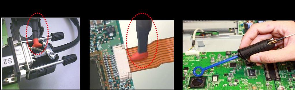
10 EMI Debugging with R&S Oscilloscope Selecting the right tools Sniffer Probes ı Basically the probes are antenna that pickup the magnetic & electric field variation ı Depending on the position & orientation, it picks up different reading 10
 General Approach ı")


11 EMI Debugging with R&S Oscilloscope Locate position of EMI faults I) General Approach ı Wide Span scan fundamental of interfering signals are usually lower than 1GHz, a span of <1GHz is sufficient as a start ı Identify abnormal spike or behavior and its location while moving the probe around ı Narrow down to smaller span and RBW, change to smaller probe for better analysis 11


12 EMI Practical Diagnosis example Locating Abnormal Spike Source with FFT Gating Our observation tell us it s an interfering signals with 80us frequency, therefore one can search through the board with Observe spikes We The Utilize Setup can interfering Culprit Notice deduced FFT Analyze Mask Gating found! that Violation signals that the interfering The tothe spike breakdown rightly signals to signal occurs detect signals appeared will that spike signals again occur behavior causes occurrence 200us at after into 80us EMI portion 80us before too such signals behaviour 12

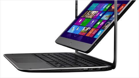
13 Touch Panel 14


14 Other Practical Example Win 8 Tablet Testing (Courtesy from RS Taiwan) Noise from Touch Panel Acoustic Noise At 8 KHz 15


15 EMI Measurements in different design phases Design Manufacturing R&D Prototype Pre-Production Manufacturing Design verifications Specifications Testing Product reviews Pre-Compliance QA Testing implementation Compliance Test New ESR3/7 Top performance High accuracy Beyond specs verifications Real- time spectrum Fast captures of spurious noise CISPR16 compliance High speed time domain scan Pre-certification EMI Test Fast & reliable Correlate time & frequency domain Fast & accurate measurements Entry level Combo of EMI test receiver & spectrum Fully automated Entry level spectrum analyzer Light weight & compact Hi performance Wide variety of measurements Good level of accuracy Reliable Many meas. functions Fastest EMI test receiver - Time domain scan - Real time spectrum - Frequency Mask Trigger - Spectrogram - Persistence Mode 16
 EMI Debugging Set (Up to 4GHz) Oscilloscope 2x H-field probes")

16 R&S Oscilloscope EMI Debugging Solution RTO HZ14 9kHz 1GHz HZ15 30MHz 3GHz HZ16 (For HZ15) EMI Debugging Set (Up to 4GHz) Oscilloscope 2x H-field probes E-field probe with built-in preamplifier Preamplifier for H-field probes Test jig for H-field probes 3x H-field probes 2x E-field probes Preamplifier 20dB 17
17 EMI Debugging with R&S Oscilloscope Summary ı The modern oscilloscope with hardware DDC and overlapping FFT is capable to do more than what the traditional oscilloscope is meant for. ı EMI Debugging with Oscilloscope correlate interfering signals with time domain with a very fast and lively update rate. ı FFT together with other mixed signal analysis on oscilloscope will allow engineers to gain different approach to isolate and converge the debugging effort easily.
Step-by-step guide Designing for EMI testing (step-by-step guide) Improve your time to market with oscilloscopes
 Improve your time to market with oscilloscopes") Step-by-step guide 01.01 Designing for EMI testing (step-by-step guide) Improve your time to market with oscilloscopes Today, R&D engineers face challenging time-to-market goals. Extending the product
Step-by-step guide 01.01 Designing for EMI testing (step-by-step guide) Improve your time to market with oscilloscopes Today, R&D engineers face challenging time-to-market goals. Extending the product
Troubleshooting EMI in Embedded Designs White Paper
 Troubleshooting EMI in Embedded Designs White Paper Abstract Today, engineers need reliable information fast, and to ensure compliance with regulations for electromagnetic compatibility in the most economical
혼합도메인오실로스코프와 USB 스팩트럼분석기를 이용한광대역노이즈최신측정기술소개
 혼합도메인오실로스코프와 USB 스팩트럼분석기를 이용한광대역노이즈최신측정기술소개 - RSA306 (USB Spectrum Analyzer), MDO Series (Mixed Domain Oscilloscope)- 텍트로닉스차경묵대리 AGENDA 1. Full compliance test vs Pre compliance test. 2. EMI Debugging
Meeting your needs R&S RTO2000 Digital Oscilloscope
 Meeting your needs R&S RTO2000 Digital Oscilloscope Multi Domain 3607.2684.32 03.00 PDP 1 en Turn your signals into success. RTO2000_fly_en_3607-2684-32_v0300.indd 3 01.02.2017 11:35:10 Best oscilloscope
R&S FSW-K54 EMI Measurement Application Detecting and eliminating electromagnetic
 R&S FSW-K54 EMI Measurement Application Detecting and eliminating electromagnetic interference Test & Measurement Product Brochure 01.00 R&S FSW-K54 EMI Measurement Application At a glance The R&S FSW-K54
Advanced Techniques for Spurious Measurements with R&S FSW-K50 White Paper
 Advanced Techniques for Spurious Measurements with R&S FSW-K50 White Paper Products: ı ı R&S FSW R&S FSW-K50 Spurious emission search with spectrum analyzers is one of the most demanding measurements in
RS Pro SPECTRUM ANALYZER SSA3000X SERIES
 Product Datasheet ENGLISH Stock No: 1236443 (RSSA3021X) 1236444 (RSSA3032X) RS Pro SPECTRUM ANALYZER SSA3000X SERIES Features and Benefits RSSA3032X XX RSSA3021X All-Digital IFTechnology Frequency Range
SSA3000X Series Spectrum Analyzer
 SSA3000X Series Spectrum Analyzer SSA3000X Spectrum Analyzer Data Sheet Features and Benefits SSA3032X SSA3021X All-Digital IF Technology Frequency Range from 9 khz up to 3.2 GHz -161 dbm/hz Displayed
SSA3000X Series Spectrum Analyzer
 SSA3000X Series Spectrum Analyzer SSA3000X Spectrum Analyzer Data Sheet Features and Benefits SSA3032X SSA3021X All-Digital IF Technology Frequency Range from 9 khz up to 3.2 GHz -161 dbm/hz Displayed
Efficient analysis of power and signal integrity and EMC
 Efficient analysis of power and signal integrity and EMC Electronic design Test and measurement solutions 5215.2914.32 PDP 1 en Turn your signals into success. 21793_002_Power-Electronics_Solution_fly_en_170627_v0101.indd
R&S FSW-B512R Real-Time Spectrum Analyzer 512 MHz Specifications
 R&S FSW-B512R Real-Time Spectrum Analyzer 512 MHz Specifications Data Sheet Version 02.00 CONTENTS Definitions... 3 Specifications... 4 Level... 5 Result display... 6 Trigger... 7 Ordering information...
Choosing an Oscilloscope
 Choosing an Oscilloscope By Alan Lowne CEO Saelig Company (www.saelig.com) Post comments on this article at www.nutsvolts.com/ magazine/article/october2016_choosing-oscilloscopes. All sorts of questions
Troubleshooting Your Design with Tektronix MSO and DPO Series Oscilloscopes
 Troubleshooting Your Design with Tektronix MSO and DPO Series Oscilloscopes Our thanks to Tektronix for allowing us to reprint the following article. Today s engineers and technicians face increasingly
R&S RTO Digital Oscilloscope Scope of the art
 RTO_bro_en_5214-2327-12.indd 1 Product Brochure 15.00 Test & Measurement R&S RTO Digital Oscilloscope Scope of the art 05.11.2014 13:20:21 R&S RTO Digital Oscilloscope At a glance The R&S RTO oscilloscopes
Timesaving Tips for Digital Debugging with a Logic Analyzer
 Timesaving Tips for Digital Debugging with a Logic Analyzer Application Note New Designs, New Headaches New digital devices have become progressively more powerful by incorporating faster microprocessors
SMS3000X Series Spectrum Analyzer
 Data Sheet SMS3000X Series Spectrum Analyzer SMS3032X SMS3021X General Description SMS3000X series spectrum analyzer has a frequency range from 9 khz up to 2.1 GHz/3.2 GHz, it is light weight and small
Meeting Embedded Design Challenges with Mixed Signal Oscilloscopes
 Meeting Embedded Design Challenges with Mixed Signal Oscilloscopes Introduction Embedded design and especially design work utilizing low speed serial signaling is one of the fastest growing areas of digital
FCC Part 15 Certification Test Report. 433 MHz Alarm System
 FCC Part 15 Certification Test Report 433 MHz Alarm System FCC ID: Q6K 1000-7253 FCC Rule Part: 15.231 ACS Report Number: 03-0111-15B Manufacturer: 3SI Security Systems Model: 1000-7253 with variants Test
R&S FSW-K160RE 160 MHz Real-Time Measurement Application Specifications
 FSW-K160RE_dat-sw_en_3607-1759-22_v0200_cover.indd 1 Data Sheet 02.00 Test & Measurement R&S FSW-K160RE 160 MHz Real-Time Measurement Application Specifications 06.04.2016 17:16:27 CONTENTS Definitions...
Real-time spectrum analyzer. Gianfranco Miele, Ph.D
 Real-time spectrum analyzer Gianfranco Miele, Ph.D www.eng.docente.unicas.it/gianfranco_miele g.miele@unicas.it The evolution of RF signals Nowadays we can assist to the increasingly widespread success
Spectrum Analyzer 1.6 GHz 3 GHz R&S HMS-X
 HMS-X_bro_de-en_3607-0181-3X_v0200.indd 1 Product Brochure 02.00 Test & Measurement Spectrum Analyzer 1.6 GHz 3 GHz R&S HMS-X 15.03.2016 15:24:06 1 Basic Unit + 3 Options Key facts Frequency range: 100
Please feel free to download the Demo application software from analogarts.com to help you follow this seminar.
 Hello, welcome to Analog Arts spectrum analyzer tutorial. Please feel free to download the Demo application software from analogarts.com to help you follow this seminar. For this presentation, we use a
News from Rohde&Schwarz Number 195 (2008/I)
") BROADCASTING TV analyzers 45120-2 48 R&S ETL TV Analyzer The all-purpose instrument for all major digital and analog TV standards Transmitter production, installation, and service require measuring equipment
BROADCASTING TV analyzers 45120-2 48 R&S ETL TV Analyzer The all-purpose instrument for all major digital and analog TV standards Transmitter production, installation, and service require measuring equipment
Improving the accuracy of EMI emissions testing. James Young Rohde & Schwarz
 Improving the accuracy of EMI emissions testing James Young Rohde & Schwarz Q&A Who uses what for EMI? Spectrum Analyzers (SA) Test Receivers (TR) CISPR, MIL-STD or Automotive? Software or front panel?
System Quality Indicators
 Chapter 2 System Quality Indicators The integration of systems on a chip, has led to a revolution in the electronic industry. Large, complex system functions can be integrated in a single IC, paving the
Dynamic re-referencing Microvolt-level measurements with the R&S RTO oscilloscopes
 RTO_app-bro_3607-2855-92_v0100.indd 1 Microvolt-level measurements with the R&S RTO Test & Measurement Application Brochure 01.00 Dynamic re-referencing Microvolt-level measurements with the R&S RTO oscilloscopes
Product Brochure Version HZ-15_16_17_bro_en_ _v0100.indd 1
 Product Brochure Version 1. R&S HZ-15/R&S HZ-17 Probe Sets R&S HZ-16 Preamplifier E and H near-field emission measurements with test receivers, spectrum analyzers and oscilloscopes HZ-15_16_17_bro_en_5213-6687-12_v1.indd
Wideband Downconverters With Signatec 14-Bit Digitizers
 Product Information Sheet Wideband Downconverters With Signatec 14-Bit Digitizers FEATURES 100 khz 27 GHz Frequency Coverage 3 Standard Selectable IF Bandwidths 100 MHz, 40 MHz, 10 MHz 3 Optional Selectable
Agilent CSA Spectrum Analyzer N1996A
 Agilent CSA Spectrum Analyzer N1996A Demonstration Guide Introduction This step-by-step demo guide will help you explore the unprecedented value of the Agilent CSA spectrum analyzer for meeting your design,
SAGE Instruments UCTT 8901 Release Notes
 SAGE Instruments UCTT 8901 Release Notes Friday June 20, 2014, Sage Instruments is excited to announce a major new release for its wireless base station test tool, model 8901 UCTT. Release Summary This
CHAPTER 3 SEPARATION OF CONDUCTED EMI
 54 CHAPTER 3 SEPARATION OF CONDUCTED EMI The basic principle of noise separator is described in this chapter. The construction of the hardware and its actual performance are reported. This chapter proposes
Wirelessly Wonderful. Solutions for IoT test challenges 5/20/2016
 5/20/2016 Wirelessly Wonderful Solutions for IoT test challenges 5/20/2016 Agenda The IoT (M2M*) applications, and technologies Major IoT Design and test challenges 1. IoT product design leveraging the
Troubleshooting Your Design with Tektronix MSO and DPO Series Oscilloscopes
 Troubleshooting Your Design with Tektronix 2 Table of Contents Troubleshooting Your Design with the MSO/DPO Series Oscilloscopes................. 4 Navigating Long Records.................................................
EMC-Scanner. HR-series
 EMC-Scanner HR-series Seeing high frequencies! Now you can SEE high frequency electromagnetic fields. Visual noise detection The fact that there is no easy way to find the exact location of a radiating
Digital Audio Design Validation and Debugging Using PGY-I2C
 Digital Audio Design Validation and Debugging Using PGY-I2C Debug the toughest I 2 S challenges, from Protocol Layer to PHY Layer to Audio Content Introduction Today s digital systems from the Digital
Technical Standards and Requirements for Radio Apparatus Capable of Receiving Television Broadcasting
 Issue 3 February 2015 Spectrum Management and Telecommunications Broadcasting Equipment Technical Standard Technical Standards and Requirements for Radio Apparatus Capable of Receiving Television Broadcasting
The Future of EMC Test Laboratory Capabilities. White Paper
 The Future of EMC Test Laboratory Capabilities White Paper The complexity of modern day electronics is increasing the EMI compliance failure rate. The result is a need for better EMI diagnostic capabilities
MSO-28 Oscilloscope, Logic Analyzer, Spectrum Analyzer
 Link Instruments Innovative Test & Measurement solutions since 1986 Store Support Oscilloscopes Logic Analyzers Pattern Generators Accessories MSO-28 Oscilloscope, Logic Analyzer, Spectrum Analyzer $ The
R&S FPC Spectrum Analyzer Unexpected performance in entry class
 R&S FPC Spectrum Analyzer Unexpected performance in entry class Product Brochure Version 04.00 year FPC_bro_en_5214-7112-12_v0400.indd 1 12.03.2018 13:36:58 R&S FPC Spectrum Analyzer At a glance Outstanding
Identifying Setup and Hold Violations with a Mixed Signal Oscilloscope APPLICATION NOTE
 Identifying Setup and Hold Violations with a Mixed Signal Oscilloscope Introduction Timing relationships between signals are critical to reliable operation of digital designs. With synchronous designs,
PicoScope 6407 Digitizer
 YE AR PicoScope 6407 Digitizer HIGH PERFORMANCE USB DIGITIZER Programmable and Powerful 1 GHz bandwidth 1 GS buffer size 5 GS/s real-time sampling Advanced digital triggers Built-in function generator
Mixed Analog and Digital Signal Debug and Analysis Using a Mixed-Signal Oscilloscope Wireless LAN Example Application
 Mixed Analog and Digital Signal Debug and Analysis Using a Mixed-Signal Oscilloscope Wireless LAN Example Application Application Note 1418 Table of Contents Introduction......................1 Debugging
Your partner in testing the Internet of Things
 Your partner in testing the Internet of Things The power of testing in all phases of the product lifecycle The majority of devices sensors, actors, gateways building the Internet of Things (IoT) use wireless
CONTENTS 6.2 TEST SET-UP...16
 CONTENTS 1. GENERAL INFORMATION...3 2. INTRODUCTION...4 3. PRODUCT INFORMATION...5 3.1 DESCRIPTION OF EUT...5 3.2 SUPPORT EQUIPMENT / CABLES USED...6 3.3 MODIFICATION ITEM(S)...6 4. DESCRIPTION OF TESTS...7
CONTENTS 1. GENERAL INFORMATION INTRODUCTION PRODUCT INFORMATION DESCRIPTION OF TESTS CHANNEL BANDWIDTH...
 Test Report Number : GETEC-E3-09-083 Page 2 / 33 CONTENTS. GENERAL INFORMATION...4 2. INTRODUCTION...5 3. PRODUCT INFORMATION...6 3. DESCRIPTION OF EUT...6 3.2 SUPPORT EQUIPMENT / CABLES USED...7 3.3 MODIFICATION
TransitHound Cellphone Detector User Manual Version 1.3
 TransitHound Cellphone Detector User Manual Version 1.3 RF3 RF2 Table of Contents Introduction...3 PC Requirements...3 Unit Description...3 Electrical Interfaces...4 Interface Cable...5 USB to Serial Interface
R&S EFL110/EFL210 Cable TV Analyzer and Leakage Detector Detecting interference in cable TV and LTE networks
 R&S EFL110/EFL210 Cable TV Analyzer and Leakage Detector Detecting interference in cable TV and LTE networks Broadcasting Product Brochure 02.00 R&S EFL110/ R&S EFL210 Cable TV Analyzer and Leakage Detector
T E S T - R E P O R T. No for PC24E-11-FC/R. RF-modem for wireless LAN. Agere Systems Nederland B.V.
 EMV-Prüfzentrum EMI/EMC-Testcenter Straubing, September 5, 2001 T E S T - R E P O R T No. 56305-10552-1 for RF-modem for wireless LAN Purpose of testing: To show compliance with FCC Code of Federal Regulations,
Tektronix RSA306 USB Spectrum Analyzer
 Tektronix RSA306 USB Spectrum Analyzer Simple Demos The Demo of the RSA306 is easy. Even you do not have signal generators, devices under test, or demo boards, using the whip antenna provided in box, you
EUTRA/LTE Downlink Specifications
 Test & Measurement Data Sheet 03.00 EUTRA/LTE Downlink Specifications R&S FS-K100PC/-K102PC/-K104PC R&S FSV-K100/-K102/-K104 R&S FSQ-K100/-K102/-K104 R&S FSW-K100/-K102/-K104 CONTENTS Definitions... 3
SIDC-5009 Series VHF/UHF WIDEBAND TUNER/CONVERTER. FREQUENCY RANGE: 20 to 3000 MHz
 SIDC-5009 Series VHF/UHF WIDEBAND TUNER/CONVERTER FREQUENCY RANGE: 20 to 3000 MHz High Dynamic Range Enables the End User to Reject Blocking Signals Often Undetected by Less Sensitive Tuners High Dynamic
Broadcast Television Measurements
 Broadcast Television Measurements Data Sheet Broadcast Transmitter Testing with the Agilent 85724A and 8590E-Series Spectrum Analyzers RF and Video Measurements... at the Touch of a Button Installing,
Max. sampling rate (realtime) channel. interleaved. 1 Gsample/s. interleaved. 2.5 Gsample/s per channel 5 Gsample/s. 5 Gsample/s per channel
 channel. interleaved. 1 Gsample/s. interleaved. 2.5 Gsample/s per channel 5 Gsample/s. 5 Gsample/s per channel") /designation Bandwidth ( db) Number of s Max. sampling rate (realtime) Memory depth Input sensitivity R&S HMO1002 digital oscilloscope 50 MHz 70 MHz 100 MHz 2 s 512 Msample/s per 1 Gsample/s 512 ksample
/designation Bandwidth ( db) Number of s Max. sampling rate (realtime) Memory depth Input sensitivity R&S HMO1002 digital oscilloscope 50 MHz 70 MHz 100 MHz 2 s 512 Msample/s per 1 Gsample/s 512 ksample
USB-SA124B Spectrum Analyzer User Manual
 USB-SA124B Spectrum Analyzer User Manual Signal Hound USB-SA124B User Manual 2017, Signal Hound 35707 NE 86 th Ave La Center, WA 98629 USA Phone (360) 263-5006 Fax (360) 263-5007 This information is being
What's the SPO technology?
 What's the SPO technology? SDS2000 Series digital storage oscilloscope, with bandwidth up to 300 MHz, maximum sampling rate 2GSa/s, a deep memory of 28Mpts, high capture rate of 110,000wfs/s, multi-level
RF Record & Playback MATTHIAS CHARRIOT APPLICATION ENGINEER
 RF Record & Playback MATTHIAS CHARRIOT APPLICATION ENGINEER Introduction Recording RF Signals WHAT DO WE USE TO RECORD THE RF? Where do we start? Swept spectrum analyzer Real-time spectrum analyzer Oscilloscope
Agilent ESA Series Spectrum Analyzers
 Agilent ESA Series Spectrum Analyzers Demonstration Guide and Application Note This demo guide is a tool to gain familiarity with the basic functions and features of the Agilent Technologies ESA-L series
PicoScope 6407 Digitizer
 YE AR HIGH PERFORMANCE USB DIGITIZER Programmable and Powerful 1 GHz bandwidth 1 GS buffer size 5 GS/s real-time sampling Advanced digital triggers Built-in function generator USB-connected Signals Analysis
Spectrum Analyzer 1.6 GHz 3 GHz HMS-X
 Spectrum Analyzer 1.6 GHz 3 GHz 1 Basic Unit + 3 Options Your Spectrum Analyzer Key facts Frequency range: 100 khz to 1.6 GHz/3 GHz* 1 Spectral purity greater than -100 dbc/hz (at 100 khz) SWEEP from 20
Time-Saving Features in Economy Oscilloscopes Streamline Test
 Time-Saving Features in Economy Oscilloscopes Streamline Test Application Note Oscilloscopes are the go-to tool for debug and troubleshooting, whether you work in &, manufacturing or education. Like other
Analyzing 8b/10b Encoded Signals with a Real-time Oscilloscope Real-time triggering up to 6.25 Gb/s on 8b/10b encoded data streams
 Presented by TestEquity - www.testequity.com Analyzing 8b/10b Encoded Signals with a Real-time Oscilloscope Real-time triggering up to 6.25 Gb/s on 8b/10b encoded data streams Application Note Application
What really changes with Category 6
 1 What really changes with Category 6 Category 6, the standard recently completed by TIA/EIA, represents an important accomplishment for the telecommunications industry. Find out which are the actual differences
DATENBLATT. SSA3000X-Serie. HABEN SIE FRAGEN ODER WÜNSCHEN SIE EIN INDIVIDUELLES ANGEBOT? Unser Team berät Sie gerne persönlich.
 DATENBLATT SSA3000X-Serie HABEN SIE FRAGEN ODER WÜNSCHEN SIE EIN INDIVIDUELLES ANGEBOT? Unser Team berät Sie gerne persönlich. TELEFON + 49 (0) 81 41/36 97-0 TELEFAX + 49 (0) 81 41/36 97-30 E-MAIL info@plug-in.de
USB-SA44B Spectrum Analyzer User Manual
 USB-SA44B Spectrum Analyzer User Manual Signal Hound USB-SA44B User Manual 2017, Signal Hound, Inc. 35707 NE 86th Ave La Center, WA 98629 USA Phone 360.263.5006 Fax 360.263.5007 This information is being
Logic Analyzer Triggering Techniques to Capture Elusive Problems
 Logic Analyzer Triggering Techniques to Capture Elusive Problems Efficient Solutions to Elusive Problems For digital designers who need to verify and debug their product designs, logic analyzers provide
Model 7330 Signal Source Analyzer Dedicated Phase Noise Test System V1.02
 Model 7330 Signal Source Analyzer Dedicated Phase Noise Test System V1.02 A fully integrated high-performance cross-correlation signal source analyzer from 5 MHz to 33+ GHz Key Features Complete broadband
Synthesized Clock Generator
 Synthesized Clock Generator CG635 DC to 2.05 GHz low-jitter clock generator Clocks from DC to 2.05 GHz Random jitter
R3267/3273 Spectrum Analyzers
 R3267/3273 Spectrum Analyzers For 3rd-Generation Mobile Communications Present Digital Communication standards (W-CDMA, PDC, PHS, IS-136, GSM, DECT, cdmaone ) R3267/3273 New communication technologies
Techniques for Extending Real-Time Oscilloscope Bandwidth
 Techniques for Extending Real-Time Oscilloscope Bandwidth Over the past decade, data communication rates have increased by a factor well over 10X. Data rates that were once 1Gb/sec and below are now routinely
R&S ETH Handheld TV Analyzer Portable DVB-T/H signal analysis up to 3.6/8 GHz
 R&S ETH Handheld TV Analyzer Portable DVB-T/H signal analysis up to 3.6/8 GHz Broadcast Product Brochure 02.00 R&S ETH Handheld TV Analyzer At a glance The R&S ETH handheld TV analyzer was specially designed
EMERSON SMART WIRELESS RADIO SILENCE REPORT
 EMERSON SMART WIRELESS RADIO SILENCE REPORT 05.21.10 Prepared by For Last updated On Friday, 2.0.docx Page 1 of 12 Table of Contents 1 Introduction... 3 1.1 Purpose & Scope... 3 1.2 Applicable Documents...
FCC Report (WIFI) Shenzhen Reo-link Digital Technology Co., Ltd B509, University Town Business Park LiShan Road, NanShan, Shenzhen, Guangdong, China
 Shenzhen Reo-link Digital Technology Co., Ltd B509, University Town Business Park LiShan Road, NanShan, Shenzhen, Guangdong, China") FCC Report (WIFI) Applicant: Address of Applicant: Manufacturer/y: Address of Manufacturer/y: Equipment Under Test (EUT) Product Name: Shenzhen Reo-link Digital Technology Co., Ltd B509, University Town
FCC Report (WIFI) Applicant: Address of Applicant: Manufacturer/y: Address of Manufacturer/y: Equipment Under Test (EUT) Product Name: Shenzhen Reo-link Digital Technology Co., Ltd B509, University Town
Application Note DT-AN DTU-315 Verification of Specifications
 DTU-315 Verification of Specifications APPLICATION NOTE January 2018 Table of Contents 1. Introduction... 3 General Description of the DTU-315... 3 Purpose of this Application Note... 3 2. Measurements...
Spectrum Analyzers. 2399A 9 khz to 3 GHz Spectrum Analyzer.
 Spectrum Analyzers 2399A 9 khz to 3 GHz Spectrum Analyzer A spectrum analyzer with outstanding performance and a user friendly visual interface simplifying many complex measurements 9 khz to 3 GHz fully
Wideband Downconverter Solutions
 GaGe wideband downconverter are wide frequency coverage receivers that feature a single RF input and 3 standard software selectable IF bandwidths, from 10 MHz to 100 MHz, or 3 optional software selectable
PicoScope 9300 Series migration guide
 sampling oscilloscopes since 2009 The 9300 Series is a leading-edge product family resulting from a long program of product development. From late 2017, in the process of adding new 15 GHz and 25 GHz models,
3GHz Spectrum Analyzer
 (9kHz ~ 3GHz) The is a swept spectrum analyzer with a 9kHz ~ 3GHz bandwidth. With high performance, a low noise floor, easy-of-use and portability, the is equally advantageous in high frequency communication
Dac3 White Paper. These Dac3 goals where to be achieved through the application and use of optimum solutions for:
 Dac3 White Paper Design Goal The design goal for the Dac3 was to set a new standard for digital audio playback components through the application of technical advances in Digital to Analog Conversion devices
Order Number : GETEC-C FCC Part 15 subpart B Test Report Number : GETEC-E Page 2 / 32 CONTENTS
 Test Report Number : GETEC-E3-12-032 Page 2 / 32 CONTENTS 1. GENERAL INFORMATION... 3 2. INTRODUCTION... 4 3. PRODUCT INFORMATION... 5 3.1 DESCRIPTION OF EUT... 5 3.2 SUPPORT EQUIPMENT / CABLES USED...
7000 Series Signal Source Analyzer & Dedicated Phase Noise Test System
 7000 Series Signal Source Analyzer & Dedicated Phase Noise Test System A fully integrated high-performance cross-correlation signal source analyzer with platforms from 5MHz to 7GHz, 26GHz, and 40GHz Key
Spectrum Master. Compact Handheld Spectrum Analyzer. Technical Data Sheet
 Technical Data Sheet Spectrum Master Compact Handheld Spectrum Analyzer MS2712E MS2713E 100 khz to 4 GHz 100 khz to 6 GHz Introduction Anritsu introduces its next generation compact handheld Spectrum Analyzers
4 MHz Lock-In Amplifier
 4 MHz Lock-In Amplifier SR865A 4 MHz dual phase lock-in amplifier SR865A 4 MHz Lock-In Amplifier 1 mhz to 4 MHz frequency range Low-noise current and voltage inputs Touchscreen data display - large numeric
Debugging a Mixed Signal Design with a Tektronix Mixed Signal Oscilloscope
 Debugging a Mixed Signal Design with a Tektronix Mixed Signal Oscilloscope Introduction Today s embedded design engineer is faced with the challenge of ever-increasing system complexity. A typical embedded
Oscilloscope Measurement Tools to Help Debug Automotive Serial Buses Faster
 Oscilloscope Measurement Tools to Help Debug Automotive Serial Buses Faster Application Note Introduction The primary reason engineers use oscilloscopes to debug and characterize automotive serial buses,
FCC Report. Beijing Visual World Technology Co.,Ltd.
 FCC Report Report No.: GTS201703000097F01 Applicant: Beijing Visual World Technology Co.,Ltd. Address of Applicant: 15th Floor and 17th Floor 1701-10A, Building 3, No. 10, Jiuxianqiao Road Jia, Chaoyang
Sharif University of Technology. SoC: Introduction
 SoC Design Lecture 1: Introduction Shaahin Hessabi Department of Computer Engineering System-on-Chip System: a set of related parts that act as a whole to achieve a given goal. A system is a set of interacting
USB-TG124A Tracking Generator User Manual
 USB-TG124A Tracking Generator User Manual Signal Hound USB-TG124A User Manual 2017, Signal Hound, Inc. 35707 NE 86th Ave La Center, WA 98629 USA Phone 360.263.5006 Fax 360.263.5007 This information is
R&S RTE Digital Oscilloscope Scope of the art
 Test & Measurement Product Brochure 04.00 R&S RTE Digital Oscilloscope Scope of the art R&S RTE Digital Oscilloscope At a glance Truly uncompromised in performance and impressively user-friendly that s
Digital Storage Oscilloscopes 2550 Series
 Data Sheet Digital Storage Oscilloscopes 2550 Series The 2550 series digital storage oscilloscopes provide high performance and value in 2-channel and 4-channel configurations. With bandwidth from 70 MHz
SIDC-5004 VHF/UHF WIDEBAND TUNER/CONVERTER. FREQUENCY RANGE: 20 to 3000 MHz
 SIDC-5004 VHF/UHF WIDEBAND TUNER/CONVERTER FREQUENCY RANGE: 20 to 3000 MHz High Dynamic Range Enables the End User to Reject Blocking Signals Often Undetected by Less Sensitive Tuners High Dynamic Range
USB Mini Spectrum Analyzer User Manual TSA Program for PC TSA4G1 TSA6G1 TSA8G1
 USB Mini Spectrum Analyzer User Manual TSA Program for PC TSA4G1 TSA6G1 TSA8G1 Triarchy Technologies Corp. Page 1 of 17 USB Mini Spectrum Analyzer User Manual Copyright Notice Copyright 2013 Triarchy Technologies,
Application Note DT-AN-2115B-1. DTA-2115B Verification of Specifations
 DTA-2115B Verification of Specifations APPLICATION NOTE January 2018 Table of Contents 1. Introduction... 3 General Description of the DTA-2115B... 3 Purpose of this Application Note... 3 2. Measurements...
Calibrate, Characterize and Emulate Systems Using RFXpress in AWG Series
 Calibrate, Characterize and Emulate Systems Using RFXpress in AWG Series Introduction System designers and device manufacturers so long have been using one set of instruments for creating digitally modulated
Application Note #63 Field Analyzers in EMC Radiated Immunity Testing
 Application Note #63 Field Analyzers in EMC Radiated Immunity Testing By Jason Galluppi, Supervisor Systems Control Software In radiated immunity testing, it is common practice to utilize a radio frequency
Report On. FCC Testing of the Pace Plc 16x4 Hybrid Gateway Cable Set Top Box COMMERCIAL-IN-CONFIDENCE
 Report On FCC Testing of the Pace Plc 16x4 Hybrid Gateway Cable Set Top Box Document 75926325 Report 01 Issue 1 April 2014 TÜV SÜD Product Service, Octagon House, Concorde Way, Segensworth North, Fareham,
Overview: Logic BIST
 VLSI Design Verification and Testing Built-In Self-Test (BIST) - 2 Mohammad Tehranipoor Electrical and Computer Engineering University of Connecticut 23 April 2007 1 Overview: Logic BIST Motivation Built-in
EMC Test Report. 850 Kacena Road Hiawatha, IA 52233
 EMC Client: EUT: Crystal Group 850 Kacena Road Hiawatha, IA 52233 Model RS112 No.: R20140819-21 Approved By: Nic S. Johnson, NCE EMC Test Engineering Manager/Technical Manager inarte Certified EMC Engineer
Oscilloscopes for debugging automotive Ethernet networks
 Application Brochure Version 01.00 Oscilloscopes for debugging automotive Ethernet networks Oscilloscopes_for_app-bro_en_3607-2484-92_v0100.indd 1 30.07.2018 12:10:02 Comprehensive analysis allows faster
EMS DATA ACQUISITION AND MANAGEMENT (LVDAM-EMS) MODEL 9062-C
 MODEL 9062-C") A Electric Power / Controls 2 kw EMS DATA ACQUISITION AND MANAGEMENT (LVDAM-EMS) MODEL 9062-C GENERAL DESCRIPTION The Lab-Volt Data Acquisition and Management for Electromechanical Systems (LVDAM-EMS),
A Electric Power / Controls 2 kw EMS DATA ACQUISITION AND MANAGEMENT (LVDAM-EMS) MODEL 9062-C GENERAL DESCRIPTION The Lab-Volt Data Acquisition and Management for Electromechanical Systems (LVDAM-EMS),
Artisan Technology Group is your source for quality new and certified-used/pre-owned equipment
 Artisan Technology Group is your source for quality new and certified-used/pre-owned equipment FAST SHIPPING AND DELIVERY TENS OF THOUSANDS OF IN-STOCK ITEMS EQUIPMENT DEMOS HUNDREDS OF MANUFACTURERS SUPPORTED