SAILOR CAS 3500/3700 Headend. Installation manual
|
|
|
- Frank Baldwin Shaw
- 5 years ago
- Views:
Transcription

1 SAILOR CAS 3500/3700 Headend Installation manual
2
3 SAILOR CAS 3500/3700 Headend Installation and maintenance manual Document number: B Release date: 14 November 2014 i
4 Disclaimer Any responsibility or liability for loss or damage in connection with the use of this product and the accompanying documentation is disclaimed by Thrane & Thrane A/S. The information in this manual is provided for information purposes only, is subject to change without notice and may contain errors or inaccuracies. Manuals issued by Thrane & Thrane A/S are periodically revised and updated. Anyone relying on this information should acquire the most current version e.g. from Service and support, or from the distributor. Thrane & Thrane A/S is not responsible for the content or accuracy of any translations or reproductions, in whole or in part, of this manual from any other source. In the event of any discrepancies, the English version shall be the governing text. Thrane & Thrane A/S is trading as Cobham SATCOM. Copyright 2014 Thrane & Thrane A/S. All rights reserved. Trademark acknowledgements Product and company names mentioned in this manual may be trademarks or trade names of their respective owners. Record of Revisions Rev. Description Release Date Initials A Original document 27 October 2014 UFO B The following tables have been edited: 8, 9, 19, November 2014 UFO ii
5 Table of contents Chapter 1 Chapter 2 Chapter 3 Chapter 4 About this manual 1.1 Intended readers Precautions... 1 Installation 2.1 General description Initial inspection To install the SAILOR CAS 3500/3700 Headend Overview Mounting considerations Output gain adjustment SAILOR CAS 3500 Headend, cabling and configuration SAILOR CAS 3700 Headend, cabling and configuration.10 BM4 VHF/UHF DSB Modulator 3.1 General description Controls on the front panel Dimensions and connectors Channel tables...18 BM450 VHF/UHF DSB Modulator 4.1 General description Controls on the front panel Dimensions and connectors Channel table...22 iii
6 Table of contents Chapter 5 App. A Maintenance 5.1 Contact for support Troubleshooting To return units for repair...24 Specifications A.1 SAILOR CAS 3500 Headend...25 A.2 SAILOR CAS 3700 Headend...27 A.3 BM450 VHF/UHF DSB Modulator...29 A.4 BM4 VHF/UHF DSB Modulator iv
7 Chapter About this manual Intended readers About this manual This is an installation manual for the SAILOR CAS 3500/3700 Headend system, intended for installers of the system and service personnel. It is important that you install the system according to the guidelines in this manual. 1.2 Precautions Text marked with Warning, Caution, Note or Important show the following type of data: Warning: A Warning is an operation or maintenance procedure that, if not obeyed, can cause injury or death. Caution: A Caution is an operation or maintenance procedure that, if not obeyed, can cause damage to the equipment. Note: A Note gives information to help the reader. Important: A text marked Important gives information that is important to the user, e.g. to make the system work properly. This text does not concern damage on equipment nor personal safety. All personnel who operate equipment or do maintenance as specified in this manual must know and follow the safety precautions. The warnings and cautions that follow apply to all parts of this manual. Warning! Before using any material, refer to the manufacturers material safety data sheets for safety information. Some materials can be dangerous. 1
8 Chapter 1: About this manual Caution! Do not use materials that are not equivalent to materials specified by Cobham SATCOM. Materials that are not equivalent can cause damage to the equipment. Caution! The system contains items that are electrostatic discharge sensitive. Use approved industry precautions to keep the risk of damage to a minimum when you touch, remove or insert parts or assemblies. 2 Precautions
9 Chapter 2 Installation General description The SAILOR CAS 3500/3700 Headend integrates all required components for a professional maritime TV/Radio-Headend system. Separate bandamplifiers make it especially suited for use in areas with high channel load by keeping inter-modulation to a minimum. It amplifies analogue as well as digital signals from long wave to UHF. Automatic Level Control circuits (ALC) help maintain the output level stable under the varying conditions aboard ships. The basic system is easily expanded to include one or more modulators. 2.2 Initial inspection Inspect the shipping cartons immediately upon receipt for evidence of damage during transport. If the shipping material is severely damaged or water stained, request that the carrier's agent be present when opening the cartons. Save all box packing material for future use Installation Warning! To avoid electric shock, do not apply power to the system if there is any sign of shipping damage to any part of the front or rear panel or the outer cover. Read the safety summary at the front of this manual before installing or operating the system. After unpacking the system, i.e. opening the cartons, inspect it thoroughly for hidden damage and loose components or fittings. If the contents are incomplete, if there is mechanical damage or defect, or if the system does not work properly, notify your dealer. 3

10 Chapter 2: Installation 2.3 To install the SAILOR CAS 3500/3700 Headend Overview For optimum system performance, some guidelines on where to install or mount the different components of the SAILOR CAS 3500/3700 Headend System must be followed. Mounting and placement details are included in this section Mounting considerations There are two ways to mount a SAILOR CAS 3500/3700 Headend: Cabinet mount for wall installation 4 To install the SAILOR CAS 3500/3700 Headend
11 19 inch rack version Chapter 2: Installation Installation Mount the headend in a dry and well-ventilated indoor environment. Mounting type Cabinet mount Cable lead Through bottom flange 19 inch rack mount Through aperture slots on the rear side as well as from the top side and bottom side Table 1: Cable lead Output gain adjustment Preferably, the output gain adjustment is done using a signal generator connected to the first input of the system (input from PS3522) and using a spectrum analyzer or a suitable TV instrument to measure signal levels throughout the network. An injected signal level of 60 dbuv should result in signal levels in all outlets in the range of dbuv, preferably closer to 60 dbuv. Minor deviations can be accepted, but at signal levels below 50dBuV analog transmissions generate a noisy picture. Levels that are too high can be reduced by adjusting the gain control on each CAS module. To install the SAILOR CAS 3500/3700 Headend 5
12 Chapter 2: Installation If there is no test equipment available, the gain adjustment is carried out by simply adjusting the gain until the picture is as good as possible in the cabins most far away and also the ones closest to the CAS system. A too strong signal might cause Moire-patterns on the screen, and too low levels will result in noisy images. In some cases the gain level of the amplifiers is not sufficient to compensate for system losses, due to long cables. The problem can be solved either by changing the cable path or by an installation of one or more line amplifiers. In some ports severe reflections from buildings, cranes etc. can cause distortion to the TV-picture due to the characteristics of the omnidirectional receiving antenna. There is no remedy for such a problem Supply voltage and cut-out relay The SAILOR CAS 3500/3700 Headend uses the SAILOR PS3522 Power Supply. This power supply handles input voltage in the range of VAC. It supplies 15 VDC voltage to the active SAILOR Mark and SAILOR VPA antennas and antenna combinations. It also supplied 24 VDC to the cassette modules. Connect the cut-out relay function to the SAILOR PS3522 using either 24 VDC control voltage or a not-energized relay or switch. Female power connector (included) N CUT OUT 24V CLOSE VDC 1,5A out L Screw connection O 7.5 mm (inner) Red Green Black Earth connection Supply voltage connection Cut-out relay connection 6 To install the SAILOR CAS 3500/3700 Headend
 to terminate all outputs that are not used.")
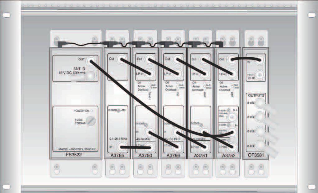
13 For a remote cut-out use one of the solutions below: Note Use only one of the solutions! 1. Provide 24 VDC between + and - terminal 2. Place a jumper between GND and - terminal. Chapter 2: Installation Antenna input Connect the antenna input to the SAILOR PS3522 to supply the active SAILOR Mark and SAILOR VPA antennas and antenna combinations. Installation SAILOR CAS 3500 Headend configuration Important Use a resistor (part number ) to terminate all outputs that are not used SAILOR CAS 3500 Headend The 19 inch rack version is shown below. To install the SAILOR CAS 3500/3700 Headend 7


14 Chapter 2: Installation SAILOR CAS 3500 Headend/BM450 The 19 inch rack version is shown below SAILOR CAS 3500 Headend/BM4 The 19 inch rack version is shown below 8 To install the SAILOR CAS 3500/3700 Headend

15 Chapter 2: Installation SAILOR CAS 3700 Headend configuration SAILOR CAS3700 Headend The 19 inch rack version is shown below Installation SAILOR CAS 3700 Headend/BM450 The 19 inch rack version is shown below. To install the SAILOR CAS 3500/3700 Headend 9

16 Chapter 2: Installation SAILOR CAS 3700 Headend/BM4 The 19 inch rack version is shown below. 10 To install the SAILOR CAS 3500/3700 Headend
17 Chapter 4 BM450 VHF/UHF DSB Modulator General description The BM450 is a double-sideband S-channel modulator that can operate in PAL B/G, D/K, I, M/N and NTSC M/N. Video and audio input levels can be adjusted from the front panel, as well as the RF output level. You can install the module in a cabinet or separately. The supply voltage is fed from the power supply to the unit by loop-connecting the supply cable from module to module. When combining the signals to a CAS 3000/CAS 3700 system take special precaution to avoid interference with terrestrial signals. Consult your distributor for further advice. Ordering information: BM 450, item number Controls on the front panel BM450 VHF/UHF DSB RF out 0-20 db Audio Levelel Video Levelel Audio x1 MHz x10 MHz x100 MHz Audio in Video in A B C D E F G H I J A - RF out, TV signal from modulator. B - Attenuator control. C - Audio, adjust the audio sub carrier, see table below. D, E and F: Adjust output frequency, see more information on the next page. G - Audio, adjust the audio input level. H - Audio signal in from e.g. VCR. I - Video, adjust the video input level. J - Video signal in from e.g. VCR. BM450 21
18 Chapter 4: BM450 VHF/UHF DSB Modulator Mounting depth required, with cables: 155 mm. To programme the module do as follows: 1. Set C to adjust the audio sub carrier. Position Frequency, system MHz PAL, NTSC, M/N MHz PAL-B/G MHz PAL-I MHz PAL-D/K MHz + test bars 6 to 9 not used. Table 6: Adjustment of audio sub carrier 2. Use D, E and F to adjust the output frequency with three switches: x100 represents 100 MHz steps, x10 represents 10 MHz steps and x1 represents 1 MHz steps. See the example below Example: To set the frequency to channel 13 (245,25 MHz), set the switches as follows: x1: 5 (5x1 MHz) x10: 4 (4x10 MHz) x100: 2 (2x100 MHz) 4.3 Dimensions and connectors See Dimensions and connectors on page Channel table See Channel tables on page Dimensions and connectors
19 Chapter 3 BM4 VHF/UHF DSB Modulator General description The BM4 VHF/UHF DSB Modulator features four separate double-sideband S-channel modulators capable of operating in PAL B/G, D/K, I, M/N and NTSC M/N. Video and audio input levels are adjustable from the front panel as well as the RF output level. The unit is especially suited for connection with the S-band input on the SAILOR CAS 3500/3700 Headend systems. You can install the module in a cabinet or separately. The supply voltage is fed from the power supply to the unit by loop-connecting the supply cable from module to module. When combining the signals to a SAILOR CAS 3500/3700 Headend take special precaution to avoid interference with terrestrial signals. Consult your distributor for further advice. Ordering information: BM 4, item number BM4 VHF/UHF DSB 13
20 5 9 Chapter 3: BM4 VHF/UHF DSB Modulator 3.2 Controls on the front panel RF out 0-20 db Level Audio Video Audio Video Audio Video Audio Video MHz Frequency/system SELECT A B C D E F H I G A - RF out, TV signal from modulator B - Attenuator C - Audio level adjustment D - Video level adjustment E - Display F - Mode frequency/system G and H - Frequency stepping buttons I - modulator selector J - Audio signal input K- Video signal input. BM4 Mounting depth required, with cables: 155 mm. To programme the module do as follows: 1. Select the modulator with the switch SELECT(1,2,3 or 4). 2. Set required frequency with stepping buttons. Available frequencies are to MHz. 3. Press the button F for mode audio sub carrier. 4. Set the required frequency with stepping, see table below. To obtain equal signal levels, use modulator 1 for the highest frequency. 14 Controls on the front panel
21 Frequency System 4.5 MHz PAL, NTSC, M/N 5.5 MHz PAL-B/G 6.0 MHz PAL-I 6.5 MHz PAL-D/K Table 2: To set the frequency Chapter 3: BM4 VHF/UHF DSB Modulator Select the desired position for the switch SELECT. Position Function 1 Modulator 1 2 Modulator 2 3 Modulator 3 BM4 VHF/UHF DSB 4 Modulator 4 5 Test bars 6 to 9 Not used Table 3: Position for the switch SELECT Controls on the front panel 15
22 Chapter 3: BM4 VHF/UHF DSB Modulator 3.3 Dimensions and connectors 16 Dimensions and connectors
23 Chapter 3: BM4 VHF/UHF DSB Modulator RF out: 75 Ohm BNC female BM4 VHF/UHF DSB Dimensions and connectors 17
24 Chapter 3: BM4 VHF/UHF DSB Modulator 3.4 Channel tables Channel Vision Channel Vision S S S S S S S S S S S S S S S S S S S S S S S S S S S S S Table 4: Channels CCIR B, G, I (European standard) Note DSB modulators: Since the modulators are of the type DSB (double side band) there must be one empty channel between the ones that are used. For example; if channel S13 is used, the S14 must be empty, meaning that the next modulator should use S15. Otherwise there will be picture distortion and interference between the modulated signals. 18 Channel tables
25 Channel Vision O P Q R S T U V W AA BB CC DD EE FF GG HH II JJ KK LL MM NN OO PP Table 5: Channels system M (6 MHz USA) Chapter 3: BM4 VHF/UHF DSB Modulator BM4 VHF/UHF DSB Channel tables 19
26 Chapter 3: BM4 VHF/UHF DSB Modulator 20 Channel tables
27 Chapter 5 Maintenance Contact for support If this manual does not provide the remedies to solve your problem, contact your local dealer. 5.2 Troubleshooting This section describes an initial check of the primary functions of the SAILOR CAS 3500/3700 Headend system, and provides some guidelines for troubleshooting. The following table provides information on some of the problems that might occur with BM450 and BM4 VHF/UHF DSB Modulators, including possible causes and remedies to solve the problem. Problem No power Indication No picture / sound after installing the system Possible cause and solution Check the AC cord coming from the power supply. 1. Check that the modulator s channel is correctly selected. 2. Video/Audio cable is not connected to modulator. 3. Check incoming cable for bad connections. 4. Modulator output level is too high/low, decrease/increase output level. Table 7: Troubleshooting guide Maintenance 23
28 Chapter 5: Maintenance Problem Picture ok, no sound Sound ok, no picture Picture full of sparkles Audio is noisy Possible cause and solution 1. Volume of control monitor too low. 2. Bad connection between audio cable from receiver to modulator. 3. Audio level of receiver / modulator is too low. 1. Bad connection of video cable. 2. Video level of receiver / modulator is too low. 1. Video frequency on receiver is not correctly tuned. 2. Modulator channel not correctly selected. 3. Poor cable connection, check cables. 1. Modulator channel not correctly selected. 2. Poor cable connection, check cables. Table 7: Troubleshooting guide (Continued) 5.3 To return units for repair Should your Cobham SATCOM product fail, please contact your dealer or installer, or the nearest Cobham SATCOM partner. You will find the partner details on where you also find the Cobham SATCOM Self Service Center web-portal, which may help you solve the problem. Your dealer, installer or Cobham SATCOM partner will assist you whether the need is user training, technical support, arranging on-site repair or sending the product for repair. Your dealer, installer or Cobham SATCOM partner will also take care of any warranty issue. 24 To return units for repair
29 Specifications SAILOR CAS 3500 Headend SAILOR CAS 3700 Headend BM450 VHF/UHF DSB Modulator BM4 VHF/UHF DSB Modulator Appendix A A AAAAA Specifications A.1 SAILOR CAS 3500 Headend Item Description Amplifier gain/frequency range AM MHz 22 ± 2 db Band I MHz 24 ± 2 db FM MHz 23 ± 2 db VHF MHz 27 ± 2 db S MHz 24 ± 2 db UHF MHz ± 2 db* Gain flatness <1 db within any channel Manual attenuation 0-20 db ALC Max. output level BI/FMVHF 110 ±2 dbμv (1 sign.) Max. output level UHF 115 ±2 dbμv (1 sign.) Range band I >50 db Range FM >45 db Range VHF >40 db Table 8: CAS 3500 specifications 23
30 Appendix A: Specifications Item Description Range UHF >30 db 3rd order inter-modulation Band I/FM/VHF/UHF <60 dbc (ALC limited) S; 8 ch, 105 dbμv <60 dbc Modulators Frequency range MHz Output level, each channel 100 dbμv General Number of outputs 4 Return loss >20 db** Impedance 75 Noise figure <7 db Supply voltage VAC Supply current max. 600 ma Antenna voltage 15 V Max antenna load 500 ma Antenna cut-out relay Yes EMC EN60945:2002, EN Operational temperature range -25 to +55 C * 4 db positive tilt ** At 40 MHz- 1.5 db/octave Table 8: CAS 3500 specifications (Continued) 24 SAILOR CAS 3500 Headend
31 A.2 SAILOR CAS 3700 Headend Item Description Amplifier gain/frequency range AM MHz 25 ± 2 db Band I MHz 27 ± 2 db FM MHz 26 ± 2 db VHF MHz 30 ± 2 db S MHz 27 ± 2 db UHF MHz ± 2 db* Gain flatness <1 db within any ch. Manual attenuation 0-20 db ALC Max. output level BI/FMVHF 113 ±2 dbμv (1 sign.) Max. output level UHF 118 ±2 dbμv (1 sign.) Range band I >50 db Range FM >45 db Range VHF >40 db Range UHF >30 db 3rd order inter-modulation Band I/FM/VHF/UHF <60 dbc (ALC limited) S; 8 ch, 105 dbμv <60 dbc Modulators Frequency range MHz Output level, each channel 100 dbμv General Table 9: CAS 3700 specifications Appendix A: Specifications AAAAA Specifications SAILOR CAS 3700 Headend 25
32 Appendix A: Specifications Item Description Number of outputs 4 Return loss >20 db** Impedance 75 Noise figure <7 db Supply voltage VAC Supply current max. 600 ma Antenna voltage 15 V Max antenna load 500 ma Antenna cut-out relay Yes EMC EN60945:2002, EN Operational temperature range -25 to +55 C * 4 db positive tilt ** At 40 MHz- 1.5 db/octave Table 9: CAS 3700 specifications (Continued) 26 SAILOR CAS 3700 Headend
33 Appendix A: Specifications A.3 BM450 VHF/UHF DSB Modulator Item Specification HF Frequency range MHz (S13-S41) Output level min 80 dbmv Frequency range, reduced output level MHz (S40 and S41) Output level min 78 dbmv Spurious output <-60 dbc Harmonics <-60 dbc Attenuation adjustment 0-20 db Output impedance 75 Ohm Modulation polarity negative Video Impedance 75 Ohm Level: nominal 500 mvpp Audio (mono) Impedance >10 kohm Level nominal 500 mvrms Pre-emphasis 50ms Miscellaneous EMC EN Operating temperature range C Supply voltage 24 VDC ± 10% Current consumption 200 ma (approx) Size (mm) (H) 210 x (W) 41x (D) 96 Table 10: BM450 VHF/UHF DSB Modulator, specifications AAAAA Specifications BM450 VHF/UHF DSB Modulator 27
34 Appendix A: Specifications A.4 BM4 VHF/UHF DSB Modulator Item Specification HF Frequency range MHz (S13-S41) Output level min. 80 dbmv Frequency range, reduced output level MHz (S40 and S41) Output level min. 78 dbv Spurious output <-60 dbc Harmonics <-60 dbc Attenuation adjustment 0-20 db Output impedance 75 Ohm Modulation polarity negative Video Impedance 75 Ohm Level nominal 500 mvpp Audio (mono) Impedance >10 kohm Level nominal 500 mvrms Pre-emphasis 50 ms Miscellaneous EMC EX Operating temperature range C Supply voltage 24 VDC ± 10% Current consumption 200 ma (approx) Size (mm) (H) 210 x (W) 41x (D) 96 Table 11: BM4 VHF/UHF DSB Modulator, specifications 28 BM4 VHF/UHF DSB Modulator
35
36 B
SAWM60 AUDIO/VIDEO MODULATOR
 SAWM60 LIMITED WARRANTY Holland Electronics LLC, warrants that the product enclosed with this Limited Warranty statement will conform to the manufacturer s specifications and be free of defects in the
HMA-860H AGILE MODULATOR
 HMA-860H AGILE MODULATOR LIMITED WARRANTY Holland Electronics LLC, warrants that the product enclosed with this Limited Warranty statement will conform to the manufacturer s specifications and be free
INSTALLATION MANUAL FT-FOTR-8VD-ST-S. 8-Channel Digital Duplex Baseband Video Transmitter and Receiver With Reverse Data Transmission for PTZ Cameras
 INSTALLATION MANUAL FT-FOTR-8VD-ST-S 8-Channel Digital Duplex Baseband Transmitter and Receiver With Reverse Transmission for PTZ Cameras v1.0 4/5/11 1 PACKAGE CONTENTS This package contains: One each
INSTALLATION MANUAL. CTMS-516RKPS Rack Mount Satellite Multiswitch
 INSTALLATION MANUAL CTMS-516RKPS Rack Mount Satellite Multiswitch 1 PACKAGE CONTENTS This package contains: One CTMS-516RKPS Rack Mount Satellite Multiswitch One CTMS-516RKPS Installation Manual PRODUCT
ENGLISH Antenna Distributor
 MANUAL ENGLISH Antenna Distributor V1 Highlite International B.V. Vestastraat 2 6468 EX Kerkrade the Netherlands Table of contents Warning... 2 Safety Instructions... 2 Operating Determinations... 4 Connection
HD-1603 Single Input MPEG-4 DVB-T HD Encoder/Modulator User Guide and Install Manual
 ZyCastR digi-mod HD Range digi-mod HD-1603 www.digi-modbyzycast.com HD-1603 Single Input MPEG-4 DVB-T HD Encoder/Modulator User Guide and Install Manual Table of Contents www.digi-modbyzycast.com Safety
PROFESSIONAL SERIES A860. Agile Modulator. Installation and Operation Manual. Operation Manual Rev. 11/05.
 PROFESSIONAL SERIES Installation and Operation Manual Operation Manual Description PROFESSIONAL SERIES Re-broadcast quality performance specifications match those of fixed channel modulators Integrated
INSTALLATION MANUAL Model: HMDD. ATSC/QAM Digital Mini Demodulator
 INSTALLATION MANUAL Model: HMDD ATSC/QAM Digital Mini Demodulator 1 PACKAGE CONTENTS This package contains: One HMDD ATSC/QAM Mini Demodulator One HMDD Installation Manual PRODUCT DESCRIPTION The HMDD
MANUAL ENGLISH Core Club Ordercode: D2314
 MANUAL ENGLISH Core Club Ordercode: Highlite International B.V. Vestastraat 2 6468 EX Kerkrade the Netherlands Table of contents Warning... 2 Unpacking Instructions... 2 Safety Instructions... 2 Operating
Colour Explosion Proof Video Camera USER MANUAL VID-C
 Colour Explosion Proof Video Camera USER MANUAL VID-C Part Number: MAN-0036-00 Rev 4 Copyright 2002 Net Safety Monitoring Inc. Printed in Canada This manual is provided for informational purposes only.
INSTALLATION MANUAL. CT-DUC-DDC Digital Off-Air Up Converter and Down Converter
 INSTALLATION MANUAL CT-DUC-DDC Digital Off-Air Up Converter and Down Converter 1 PACKAGE CONTENTS This package contains: One CT-DUC Digital Off-Air Up Converter One CT-DDC Digital Off-Air Down Converter
QCA9-33 Active Combiner
 Product Manual QCA9-33 Active Combiner April 13, 2012 Table of Contents Table of Contents... 2 Overview... 3 Specifications... 4 Installation... 5 Basic Setup... 5 16-Channel Operation... 5 16-64 Channel
INSTALLATION MANUAL FT-FOTR-1VDE-ST-S
 INSTALLATION MANUAL FT-FOTR-1VDE-ST-S 1-Channel Digital Duplex Baseband Video Transmitter and Receiver With Reverse Data Transmission & Ethernet Transmission v1.0 4/5/11 1 PACKAGE CONTENTS This package
PAM-1840 Preamplifier Operation Manual
 PAM-1840 Preamplifier Operation Manual 1 TABLE OF CONTENTS INTRODUCTION 3 GENERAL INFORMATION 4 SPECIFICATIONS 4 OPERATING INSTRUCTIONS 5 MAINTENANCE 6 2 INTRODUCTION BEFORE APPLYING POWER Review this
OPERATOR MANUAL OSD8865 DIGITAL TRIPLE VIDEO FIBER OPTIC RECEIVER
 OPERATOR MANUAL OSD8865 DIGITAL TRIPLE VIDEO FIBER OPTIC RECEIVER INDEX 1 1 TECHNICAL SUMMARY... 4 1.1 BRIEF DESCRIPTION... 4 1.1.1 OVERVIEW... 4 1.1.2 APPLICATIONS... 4 1.1.3 FEATURES AND BENEFITS...
HD-1600 Single Input MPEG-4 DVB-T HD Encoder/Modulator User Guide and Install Manual
 digi-mod HD Range digi-mod HD-1600 www.resi-linx.com HD-1600 Single Input MPEG-4 DVB-T HD Encoder/Modulator User Guide and Install Manual Table of Contents Safety Precautions 2 Package Contents 2 Product
ACTIVE IF SPLITTER/COMBINER UHP-IFS
 ACTIVE IF SPLITTER/COMBINER UHP-IFS GENERAL DESCRIPTION AND INSTALLATION GUIDE DOCUMENT RELEASE 2 [UHP.IFS.2.EN] JUNE 2016 CONTENT Acronyms and Abbreviations... 4 Introduction... 5 Required level of qualification...
384A Adapter Installation Instructions
 Instruction Sheet 860237684 Issue 9, October 2012 SYSTIMAX Solutions 384A Adapter Installation Instructions General The 384A adapter (Figure 1) is a broadband video adapter that provides connectivity to
Concert Series ORDERCODE D3470 ORDERCODE D3471 ORDERCODE D3472 D3470 D3471 D3472
 Concert Series ORDERCODE D3470 ORDERCODE D3471 ORDERCODE D3472 D3470 D3471 D3472 Congratulations! You have bought a great, innovative product from DAP Audio. The DAP Audio Concert Series brings excitement
OTM-3550-SW FREQUENCY AGILE F.C.C. COMPATIBLE TELEVISION MODULATOR INSTRUCTION MANUAL
 FREQUENCY AGILE F.C.C. COMPATIBLE TELEVISION MODULATOR INSTRUCTION MANUAL Phone: (209) 586-1022 (800) 545-1022 Fax: (209) 586-1026 E-Mail: salessupport@olsontech.com 025-000233 REV E www.olsontech.com
Instruction Manual. 4x1 VGA Routing Switcher Series
 MULTIMEDIA AUDIO AND VISUAL Instruction Manual MODEL : SB-406 4x VGA ROUTING SWITCHER 4x VGA Routing Switcher Series Thank you for purchasing the SB-406 VGA Router Switcher. You will find this unit easy
TC Mbps - 622Mbps FIBER OPTIC MODE CONVERTER/REPEATER (Rev A0.1) User's Manual
 User's Manual") TC3004 50Mbps - 622Mbps FIBER OPTIC MODE CONVERTER/REPEATER (Rev A0.1) MODEL: S/N: DATE: Notice! Although every effort has been made to insure that this manual is current and accurate as of date of publication,
TC3004 50Mbps - 622Mbps FIBER OPTIC MODE CONVERTER/REPEATER (Rev A0.1) MODEL: S/N: DATE: Notice! Although every effort has been made to insure that this manual is current and accurate as of date of publication,
INSTALLATION MANUAL. Model: HDD. ATSC/QAM Digital to Analog Demodulator
 INSTALLATION MANUAL Model: HDD ATSC/QAM Digital to Analog Demodulator Caution: These servicing instructions are for use by qualified service personnel only. To reduce the risks of electric shock, do not
Chameleon Labs Model 7720
 Chameleon Labs Model 7720 Stereo Compressor Owner s Manual 704 228 th Avenue NE, # 826 Sammamish, WA 98074 206-264-7602 www.chameleonlabs.com Revision C - December, 2007 UNPACKING AND INSPECTION Carefully
RFT-851FTA. Twin DVB-T to PAL remodulator. User Manual
 RFT-851FTA Twin DVB-T to PAL remodulator User Manual 1. Purpose of use RFT-851FTA is designed for prosessing two COFDM modulated signals into standard CCIR channels. RFT-851FTA is supplied with a A2 stereo/dual/swap
PERFORMANCE SPECIFICATIONS*
 PERFORMANCE SPECIFICATIONS* 18T-2127 26T-2127 Reflector Material Mounting Hardware Gain Input Frequency** -3 db Beam Width Cross Polarity Rejection Front to Back Ratio Impedance @ Output Elevation Adjustment
USER INSTRUCTIONS MODEL CSI-200 COAXIAL SYSTEM INTERFACE
 USER INSTRUCTIONS MODEL CSI-200 COAXIAL SYSTEM INTERFACE 9350-7676-000 Rev B, 5/2001 PROPRIETARY NOTICE The RTS product information and design disclosed herein were originated by and are the property of
2.4 GHz WIRELESS VIDEO SENDER SYSTEM MODEL: VS6234
 2.4 GHz WIRELESS VIDEO SENDER SYSTEM MODEL: VS6234 Please read this manual thoroughly before operating this system OPERATING INSTRUCTIONS 03/02 1 SAFETY INSTRUCTIONS CAUTION! RISK OF ELECTRIC SHOCK. DO
Register your product and get support at SDV5122/27. EN User manual
 Register your product and get support at www.philips.com/welcome SDV5122/27 User manual Contents 1 Important 4 Safety 4 Notice for USA 5 Notice for Canada 5 Recycling 6 English 2 Your SDV5122 7 Overview
CardModule. Reference Manual. Series C DA Channel SDI to CVBS Converter. Version 1.0
 Reference Manual C DA 5005 5 Channel SDI to CVBS Converter Version 1.0 Series 5000 CardModule LYNX Technik AG Brunnenweg 3 D-64331 Weiterstadt Germany www.lynx-technik.com Information in this document
Passive Four Channel Stereo/Mono Mixer/Splitter. Artcessories. User's Manual
 Passive Four Channel Stereo/Mono Mixer/Splitter Artcessories User's Manual IMPORTANT SAFETY INSTRUCTION READ FIRST This symbol, whenever it appears, alerts you to the presence of uninsulated dangerous
QDA4-44 RF Amp/Combiner
 Product Manual QDA4-44 RF Amp/Combiner May 17, 2012 Table of Contents Table of Contents... 2 Overview... 3 Specifications... 4 Installation... 5 Basic Setup... 5 Rack Mounting... 6 RK2 Dual Rack Kit with
Model /29S RF Splitter
 Instruction Manual Model 1584-29/29S RF Splitter March 2013, Rev. 0 LNB VOLTAGE A B MODEL 1584 COMBINER CROSS TECHNOLOGIES INC. GND+DC ON Data, drawings, and other material contained herein are proprietary
CPH-10 SUBWOOFER OWNERS MANUAL
 CPH-10 SUBWOOFER OWNERS MANUAL www.artcoustic.com Welcome to the world of Artcoustic! Congratulations with your purchase of the Artcoustic CPH-10 Subwoofer. The CPH-10 has an efficient design, producing
MX-206 Stereo Microphone Mixer. Operating Manual
 MX-206 Stereo Microphone Mixer Operating Manual ASHLY AUDIO INC. 847 Holt Road Webster, NY 14580-9103 Phone: (585) 872-0010 Toll-Free: (800) 828-6308 Fax: (585) 872-0739 www.ashly.com Operating Manual
 I R T Electronics Pty Ltd A.B.N. 35 000 832 575 26 Hotham Parade, ARTARMON N.S.W. 2064 AUSTRALIA National: Phone: (02) 9439 3744 Fax: (02) 9439 7439 International: +61 2 9439 3744 +61 2 9439 7439 Email:
OTD-3000 FREQUENCY AGILE TELEVISION DEMODULATOR INSTRUCTION MANUAL
 OTD-3000 FREQUENCY AGILE TELEVISION DEMODULATOR INSTRUCTION MANUAL Phone: (209) 586-1022 (800) 545-1022 Fax: (209) 586-1026 E-Mail: salessupport@olsontech.com 025-000053 REV G www.olsontech.com 6/22/01
INSTALLATION MANUAL. ST-CVTSD520-WSD-W Smoke Detector Covert Camera. v1.2 8/11/11 1
 INSTALLATION MANUAL ST-CVTSD520-WSD-W Smoke Detector Covert Camera v1.2 8/11/11 1 PACKAGE CONTENTS This package contains: One ST-CVTSD520-WSD-W smoke detector covert camera One installation manual Mounting
Operation Manual. VR75 Series UHF, L, S, C-Band Video / Audio Receivers
 Operation Manual VR75 Series UHF, L, S, C-Band Video / Audio Receivers Designed and Manufactured By Distributed By 7025 Longley Lane, Suite 20 Reno, NV 89511 107 Woodbine Down Blvd, Units 7&8 Toronto,
INSTRUCTIONS FOR USE Pro-Ject Receiver Box S
 INSTRUCTIONS FOR USE Pro-Ject Receiver Box S Dear music lover, thank you for purchasing a PRO-JECT AUDIO receiver. In order to achieve maximum performance and reliability you should study these instructions
Z-IP Stream 004/008. User Guide and Installation Manual. Four or Eight Input QAM Encoder / Modulator
 Z-IP Stream 004/008 User Guide and Installation Manual Four or Eight Input QAM Encoder / Modulator MPEG-2 / H.264 HD ENCODER with QAM /IP/ & ASI Outputs Contents Safety Precautions... 3 Package Contents...
Instructions for Use P.154-UP (9/4) P.155-UP (9/8) P.150-UP-12 (9/12) P.150-UP-16 (9/16)
 P.155-UP (9/8) P.150-UP-12 (9/12) P.150-UP-16 (9/16)") Satellite multiswitch Instructions for Use P.154-UP (9/4) P.155-UP (9/8) P.150-UP-12 (9/12) P.150-UP-16 (9/16) EMP-CENTAURI is a registered trademark Dear Customer, Thank you for buying the EMP-Centauri
Satellite multiswitch Instructions for Use P.154-UP (9/4) P.155-UP (9/8) P.150-UP-12 (9/12) P.150-UP-16 (9/16) EMP-CENTAURI is a registered trademark Dear Customer, Thank you for buying the EMP-Centauri
Instruction Manual Model # Block Upconverter
 Instruction Manual Model 2115-278# Block Upconverter August 2018, Rev. A MODEL 2115 UPCONVERTER CROSS TECHNOLOGIES INC. EXT 10MHZ ALARM POWER Data, drawings, and other material contained herein are proprietary
LCM-6550 TRIPLE TELEVISON MODULATOR INSTRUCTION MANUAL
 LCM-6550 TRIPLE TELEVISON MODULATOR INSTRUCTION MANUAL Phone: (209) 586-1022 (800) 545-1022 Fax: (209) 586-1026 E-Mail: salessupport@olsontech.com 025-000244 REV E www.olsontech.com 6/21/01 LCM-6550 TRIPLE,
Connevans.info. DeafEquipment.co.uk. This product may be purchased from Connevans Limited secure online store at
 Connevans.info Solutions to improve the quality of life Offering you choice Helping you choose This product may be purchased from Connevans Limited secure online store at www.deafequipment.co.uk DeafEquipment.co.uk
Operating Instructions 07/2007 Edition. SINAMICS G130/G150 Line harmonics filter. sinamics
 Operating Instructions 07/2007 Edition SINAMICS G130/G150 Line harmonics filter sinamics s Safety information 1 General 2 SINAMICS SINAMICS G130/G150 Operating Instructions Mechanical installation 3 Electrical
DM-1CH SD DVB-T MODULATOR INSTRUCTION MANUAL
 DM-1CH SD DVB-T MODULATOR INSTRUCTION MANUAL 2. Caution Statements and Table of Contents Table of Contents 2. Caution Statements and Table of contents 3. Important Safety Instructions 4. Important Safety
MAXCOM PRODUCT SPECIFICATIONS FIBER OPTIC VIDEO / AUDIO / ASI LINK. Model MX3257HD. Description. Features. Model Selection Guide
 MAXCOM PRODUCT SPECIFICATIONS FIBER OPTIC VIDEO / AUDIO / ASI LINK Model MX3257HD Description The rack-mountable MX3257HD fiber optic video multiplexer is ideal for transmitting 1 channel of video, 2 channels
MON8-1 1U 8-Channel Multi-Display Video Monitor
 MON8-1 1U 8-Channel Multi-Display Video Monitor with Eight Backlit 1.75" LCD Displays, Eight CVBS Video Inputs, and Eight Loop-through Outputs Document P/N 821568 Rev-A User Manual CONTENTS Title and Contents...
IRT Eurocard. Type RWA RF Distribution Amplifier for 70 MHz IF signals
 I R T Electronics Pty Ltd A.B.N. 5 000 8 575 6 Hotham Parade, ARTARMON N.S.W. 064 AUSTRALIA National: Phone: (0) 949 744 Fax: (0) 949 749 International: +6 949 744 +6 949 749 Email: sales@irtelectronics.com
32 Channel CPCI Board User Manual
 0 Sections Page 1.0 Introduction 1 2.0 Unpacking and Inspection 1 3.0 Hardware Configuration 1 4.0 Board Installation 5 5.0 I/O Connections and the Front Panel 5 5.1 Front Panel Layout 5 5.2 Input and
ST-4000D SIGNAL LEVEL METER
 ST-4000D SIGNAL LEVEL METER Rev 100606 Table of Contents Features / Specifications.... 1 Keypad Illustration....... 2 Keypad Controls.... 2 Getting Started: Powering the Meter...... 3 Quick Use Instructions.....
music hall pa2.2 INSTRUCTION MANUAL music hall
 music hall pa2.2 INSTRUCTION MANUAL music hall http://www.musichallaudio.com CONGRATULATIONS ON YOUR PURCHASE You have selected an exceptional phono preamplifier. Each component used in the construction
LCM-550x12 12 CHANNEL TELEVISION MODULATOR SYSTEM INSTRUCTION MANUAL
 LCM-550x12 12 CHANNEL TELEVISION MODULATOR SYSTEM INSTRUCTION MANUAL Phone: (209) 586-1022 (800) 545-1022 Fax: (209) 586-1026 E-Mail: salessupport@olsontech.com 025-000329 REV C www.olsontech.com 6/1/01
SignalOn Series. L-Band Power Inserter Module INSTALLATION & OPERATION MANUAL. 1.2 GHz. D3.
 SignalOn Series D3.1/CCAP Compliant 1.2 GHz L-Band Power Inserter Module INSTALLATION & OPERATION MANUAL www.atxnetworks.com www.atxnetworks.com Although every effort has been taken to ensure the accuracy
Trinitron Color TV KV-XF21M80. Operating Instructions (1)
") 3-866-0- () Trinitron Color TV Operating Instructions Before operating the unit, please read this manual thoroughly and retain it for future reference. GB CT CS KV-XFM80 999 by Sony Corporation WARNING
3-866-0- () Trinitron Color TV Operating Instructions Before operating the unit, please read this manual thoroughly and retain it for future reference. GB CT CS KV-XFM80 999 by Sony Corporation WARNING
508 Phono Preamplifier. Boulder Amplifiers, Inc. 255 S. Taylor Ave. Louisville, CO (303) /1/2018 Rev. 1.
 /1/2018 Rev. 1.") 508 Phono Preamplifier 6/1/2018 Rev. 1.0 P/N: 91053 Boulder Amplifiers, Inc. 255 S. Taylor Ave. Louisville, CO 80027 (303) 449-8220 www.boulderamp.com About About Boulder Amplifiers, Inc. Boulder was founded
508 Phono Preamplifier 6/1/2018 Rev. 1.0 P/N: 91053 Boulder Amplifiers, Inc. 255 S. Taylor Ave. Louisville, CO 80027 (303) 449-8220 www.boulderamp.com About About Boulder Amplifiers, Inc. Boulder was founded
UTP ACTIVE TRANSCEIVER HUB
 VI6116 UTP ACTIVE TRANSCEIVER HUB USER S MANUAL 7810 Trade Street, Suite 100 San Diego, CA 92121, U.S.A. Phone: (858) 484-5209 Fax: (858) 484-1205 1 1. Introduction The Vigitron VI6116 is a 16 port active
Instructions for Use P.160-AP-8 (13/8) P.160-CP-8 (13/8) P.160-CP-12 (13/12) P.160-CP-16 (13/16)
 P.160-CP-8 (13/8) P.160-CP-12 (13/12) P.160-CP-16 (13/16)") Satellite multiswitch Instructions for Use P.160-AP-8 (13/8) P.160-CP-8 (13/8) P.160-AP-12 (13/12) P.160-CP-12 (13/12) P.160-AP-16 (13/16) P.160-CP-16 (13/16) EMP-CENTAURI is a registered trademark Dear
Satellite multiswitch Instructions for Use P.160-AP-8 (13/8) P.160-CP-8 (13/8) P.160-AP-12 (13/12) P.160-CP-12 (13/12) P.160-AP-16 (13/16) P.160-CP-16 (13/16) EMP-CENTAURI is a registered trademark Dear
ADR-1000AS Compact Modular SMATV Headend
 ADR-1000AS Compact Modular SMATV Headend ADR-1000AS is a compact modular SMATV headend, supporting up to 16 channels in one 19 4U chassis. It integrates multiple functions including DTV signal reception,
MAW-201 (3031) MULTISTANDARD VHF/UHF TV MODULATOR
 MULTISTANDARD VHF/UHF TV MODULATOR") MAW-201 (3031) MULTISTANDARD VHF/UHF TV MODULATOR GENERAL DESCRIPTION The MAW-201 modulator generates double sideband, mono sound TV channels of the systems B/G/D/K/I/L/M/N/Australia. Appropriate use with
MAW-201 (3031) MULTISTANDARD VHF/UHF TV MODULATOR GENERAL DESCRIPTION The MAW-201 modulator generates double sideband, mono sound TV channels of the systems B/G/D/K/I/L/M/N/Australia. Appropriate use with
M5-H002. Multiview T-35. DVB-T to PAL / 5 channels on all TV s
 120531 M5-H002 Multiview T-35 DVB-T to PAL / 5 channels on all TV s Contents Multiview... 3 Features... 3 Caution... 3 Front & Rear Panel... 4 Connecting... 5 Programming... 6 Information... 7 Installation...8
Model 1421 Distribution Amplifier
 Model 1421 Distribution Amplifier Installation and Operating Instructions The 1421 Distribution Amplifier provides four independent, wide bandwidth outputs from one video input. The unit is color compatible
MODEL OTM-4870 FREQUENCY AGILE 870MHz F.C.C. COMPATIBLE TELEVISION MODULATOR
 MODEL OTM-4870 FREQUENCY AGILE 870MHz F.C.C. COMPATIBLE TELEVISION MODULATOR USERS MANUAL Phone: (209) 586-1022 (800) 545-1022 Fax: (209) 586-1026 E-Mail: salessupport@olsontech.com 025-000412 Rev. B www.olsontech.com
FD Trinitron Colour Television
 R 4-205-569-32(1) FD Trinitron Television Instruction Manual GB KV-14LM1U 2000 by Sony Corporation NOTICE FOR CUSTOMERS IN THE UNITED KINGDOM A moulded plug complying with BS1363 is fitted to this equipment
HD Digital MPEG2 Encoder / QAM Modulator
 HD Digital MPEG2 Encoder / QAM Modulator HDMI In QAM Out series Get Going Guide ZvPro 800 Series is a one or two-channel unencrypted HDMI-to-QAM MPEG 2 Encoder / QAM Modulator, all in a compact package
TVAC20000 User manual
 TVAC20000 User manual Version 01/2010 Original English user manual. Keep for future use. 10 Introduction Dear Customer, Thank you for purchasing this product. This product meets the requirements of the
ST-4000 SIGNAL LEVEL METER
 ST-4000 SIGNAL LEVEL METER Table of Contents Features / Specifications.... 1 Keypad Illustration....... 2 Keypad Controls.... 2 Getting Started: Powering the Meter.... 3 Quick Use Instructions.. 3 Main
Phono Amplifier brinkmann «EDISON» Manual.
 Phono Amplifier brinkmann «EDISON» ----------------------------------------------------------------------------------------------- Manual Preface We congratulate you on the purchase of our «EDISON» phono
.Power Distribution Center. PD-1. Instruction Manual
 .Power Distribution Center. PD-1 Instruction Manual www.datavideo-tek.com 1 Contents Warnings and Precautions... 3 Warranty... 4 Standard Warranty... 4 Two Year Warranty... 4 Disposal... 4 Packing List...
OPERATOR MANUAL OSD390 SERIES 4 CHANNEL VIDEO/AUDIO/DATA FIBER OPTIC TRANSMISSION SYSTEM
 PTY. LTD A.B.N. 83 003 020 504 OPERATOR MANUAL OSD390 SERIES 4 CHANNEL VIDEO/AUDIO/DATA FIBER OPTIC TRANSMISSION SYSTEM OSD390 SERIES 4 CHANNEL VIDEO/AUDIO/DATA FIBER OPTIC TRANSMISSION SYSTEM Document
Traditional RF Splitter/Combiner and Directional Coupler User Manual
 Traditional RF Splitter/Combiner and Directional Coupler User Manual Content Page INTRODUCTION... 1 Revision History... 2 Trademark Information... 2 Admonishments... 2 General Safety Precaution... 2 1
 Register your product and get support at www.philips.com/welcome SDV5222T/27 User manual Contents 1 Important 4 Safety 4 Notice for USA 4 Notice for Canada 5 Recycling 5 English 2 Your SDV5222T 6 Overview
MASTR II BASE STATION 12/24V POWER SUPPLY 19A149979P1-120 VOLT/60 Hz 19A149979P2-230 VOLT/50 Hz
 Mobile Communications MASTR II BASE STATION 12/24V POWER SUPPLY 19A149979P1-120 VOLT/60 Hz 19A149979P2-230 VOLT/50 Hz CAUTION THESE SERVICING INSTRUCTIONS ARE FOR USE BY QUALI- FIED PERSONNEL ONLY. TO
QRF5000 MDU ENCODER. Data Sheet
 Radiant Communications Corporation 5001 Hadley Road South Plainfield NJ 07080 Tel (908) 757-7444 Fax (908) 757-8666 WWW.RCCFIBER.COM QRF5000 MDU ENCODER Data Sheet Version 1.1 1 Caution Verify proper grounding
SATRI AMPLIFIER AMP-51R. Owner s Manual
 SATRI AMPLIFIER AMP-51R Owner s Manual contents SAFETY INSTRUCTIONS 4 INTRODUCTION 6 OVERVIEW (FRONT PANEL) 8 OVERVIEW (REAR PANEL) 9 OVERVIEW (REMOTE CONTROL) 1 1 OPERATION 12 TROUBLESHOOTING 13 SPECIFICATION
USB-TG124A Tracking Generator User Manual
 USB-TG124A Tracking Generator User Manual Signal Hound USB-TG124A User Manual 2017, Signal Hound, Inc. 35707 NE 86th Ave La Center, WA 98629 USA Phone 360.263.5006 Fax 360.263.5007 This information is
CAM Series Channelized Agile Audio/Video Modulators
 CAM Series Channelized Agile Audio/Video Modulators Features & Benefits EAS/ALT IF Ready Via Manual or Automatic Mode Front Panel Accessible Level Controls for Easy Set-Up and Adjustments Rack Mountable
User Guide Supplement M4 ( MHz) CONTENTS UHF WIRELESS SYSTEM
 CONTENTS UHF WIRELESS SYSTEM") User Guide Supplement M4 (662-692 MHz) UHF WIRELESS SYSTEM CONTENTS SPECIFICATIONS... 2 FURNISHED ACCESSORIES... 5 OPTIONAL ACCESSORIES... 6 REPLACEMENT PARTS... 6 UHF WIRELESS SYSTEM COMPATIBILITY GUIDE...
User Guide Supplement M4 (662-692 MHz) UHF WIRELESS SYSTEM CONTENTS SPECIFICATIONS... 2 FURNISHED ACCESSORIES... 5 OPTIONAL ACCESSORIES... 6 REPLACEMENT PARTS... 6 UHF WIRELESS SYSTEM COMPATIBILITY GUIDE...
CONVI104 SWITCHER & ANALOG TO SDI CONVERTER CONVI 104-M 15/03/2006
 PAL and NTSC compatible 10-bit sampling Five-stage comb filter EDH generation and insertion Twin SDI output Frame Synch. with optional board (FS104) CONVI 104-M 15/03/2006 1 INSTALLATION AND USE OF THE
Frequency. Range. HP 83751A/B: 2 GHz to 20 GHz HP 83752A/B: 10 MHz to 20 GHz. Standard 10 MHz timebase: f10 ppm
 Frequency Range HP 83751A/B: 2 GHz to 20 GHz HP 83752A/B: 10 MHz to 20 GHz Timebase Stability Standard 10 MHz timebase: f10 ppm High stability timebase (Option le5): Accuracy = Calibration &Aging rate
Multi Channel Programmable Filter-Equalizer. Use Manual. Digital. Terrestrial. Ref. : 6505
 R Ref. : 60 Multi Channel Programmable Filter-Equalizer Use Manual 1 2 3 4 6 7 8 9 GND Terrestrial MULTI CHANNEL PROGRAMMABLE FILTER-EQUALIZER Terrestrial Ref. : 60 32 R UHF +V /00 ma FEATURES - Designed
Operating Manual (Edition 04/2004) sinamics. Line Reactors SINAMICS G130
 sinamics. Line Reactors SINAMICS G130") Operating Manual (Edition 04/2004) sinamics Line Reactors SINAMICS G130 Contents 1. Safety Information 2 2. General 5 3. Mechanical Installation 6 4. Electrical Installation 8 5. Technical Specifications
Operating Manual (Edition 04/2004) sinamics Line Reactors SINAMICS G130 Contents 1. Safety Information 2 2. General 5 3. Mechanical Installation 6 4. Electrical Installation 8 5. Technical Specifications
OPERATION MANUAL. USF-402AADC Audio Analog Digital Converter. 1 st Edition
 OPERATION MANUAL USF-402AADC Audio Analog Digital Converter 1 st Edition Precautions Important Safety Warnings [Operation] Hazard [Transportation] Hazard [Circuitry Access] Do not operate the unit under
Model Camera System (CCTV) User Manual
 User Manual") Model 4330 Camera System (CCTV) User Manual ETS-Lindgren L.P. reserves the right to make changes to any product described herein in order to improve function, design, or for any other reason. Nothing contained
Model 4330 Camera System (CCTV) User Manual ETS-Lindgren L.P. reserves the right to make changes to any product described herein in order to improve function, design, or for any other reason. Nothing contained
Model:P19LCD. 16:10 DIGITAL LCD-TV-Monitor 19 LCD TELEVISION OPERATING MANUAL.
 Model:P19LCD 16:10 DIGITAL LCD-TV-Monitor 19 LCD TELEVISION OPERATING MANUAL www.pyleaudio.com CONTENTS 1. PREFACE........... 2. SAFETY PRECAUTIONS... 3. FRONT, BACK, CONNECTIONS OF LCD...... 4. TV INSTALLATION
INSTRUCTION MANUAL MODEL 2710 SUBCARRIER DEMODULATOR
 INSTRUCTION MANUAL MODEL 2710 SUBCARRIER DEMODULATOR Data, drawings, and other material contained herein are proprietary to Cross Technologies, Inc., and may not be reproduced or duplicated in any form
INSTALLATION MANUAL. ST-CVTMD420-WPIR-W Covert Motion Detection Color Camera. v1.3 8/11/11 1
 INSTALLATION MANUAL ST-CVTMD420-WPIR-W Covert Motion Detection Color Camera v1.3 8/11/11 1 PACKAGE CONTENTS This package contains: One ST-CVTMD420-WPIR-W covert motion detection camera One installation
Be sure to run the vehicle engine while using this unit to avoid battery exhaustion.
 CAUTION: TO REDUCE THE RISK OF ELECTRIC SHOCK DO NOT REMOVE COVER (OR BACK) NO USER-SERVICEABLE PARTS INSIDE REFER SERVICING TO QUALIFIED SERVICE PERSONNE; Please Read all of these instructions regarding
6170 Shiloh Road Alpharetta, Georgia (770) FAX (770) Toll Free
 FAX (770) Toll Free") Instruction Manual Model 2115-202 Upconverter November 2011, Rev. C MODEL 2115 UPCONVERTER CROSS TECHNOLOGIES INC. EXT 10MHZ ALARM POWER Data, drawings, and other material contained herein are proprietary
Instruction Manual Model 2115-202 Upconverter November 2011, Rev. C MODEL 2115 UPCONVERTER CROSS TECHNOLOGIES INC. EXT 10MHZ ALARM POWER Data, drawings, and other material contained herein are proprietary
Model: S-4904T/R. Wireless HD Transmission System. User Manual. Please read this User Manual throughout before using.
 Model: S-4904T/R Wireless HD Transmission System User Manual Please read this User Manual throughout before using. Preface Congratulations on your purchase of this product. Please read this user manual
By CHANNEL VISION. Flush Mount Amplifier A0350
 Spkrs Local In IR In 24VDC A0350 10 The A0350 can be used with Channel Vision s CAT5 audio hubs to provide a powerful 50Watts per channel in the listening zone. Alternatively, the A0350 can be added to
Indoor/Outdoor Security System with Quad Monitor User s Manual
 Indoor/Outdoor Security System with Quad Monitor User s Manual 4919539 Important! Please read this booklet carefully before installing or using these units. WARNING - These units should ONLY be opened
Traditional RF Splitter/Combiner and Directional Coupler User Manual
 Traditional RF Splitter/Combiner and Directional Coupler User Manual Content Page INTRODUCTION... 1 Revision History... 2 Trademark Information... 2 Admonishments... 2 General Safety Precaution... 2 1
Four-Way Antenna Signal Booster. User Manual
 User Manual RETAIN THIS MANUAL FOR FUTURE REFERENCE PLEASE READ THIS MANUAL CAREFULLY BEFORE USE Table of Contents INTRODUCTION... 1 INSTALLING THE FOUR-WAY ANTENNA SIGNAL BOOSTER... 2 Method 1... 2 Method
DANGER. DANGER indicates a hazardous situation which, if not avoided, will result in death or serious injury. WARNING
 Installation Guide Smart-UPS C 1000/1500 VA 120/230 Vac 2000/3000 VA 230 Vac Tower Important Safety Messages SAVE THESE INSTUCTIONS - This manuals contains important instructions that should be followed
User s manual OLY 9X K OLY 9X OLY 9V. User s Guide. Headend cascade multiswitch OLY 9X K Cascade multiswitch OLY 9X. Cascade line amplifier OLY 9V
 Chapter 1. Installation. 1.1. Safety Measures 1.- Never place the device next to hot sources. 2.- Never undergo the device to temperatures that exceed its level of operation. 3.- Never expose the device
CS x1 RS-232 Computer Controlled Video Switcher. Instruction Manual
 CS-1600 16x1 RS-232 Computer Controlled Video Switcher Instruction Manual Thank you for purchasing one of our products. Please read this manual before using this product. When using this product, always
bel canto SEP2 Single Ended Triode Tube Preamplifier User's Guide and Operating Information
 bel canto SEP2 Single Ended Triode Tube Preamplifier User's Guide and Operating Information Bel Canto Design 212 Third Avenue North, Suite 274 Minneapolis, MN 55401 USA Phone: 612 317.4550 Fax: 612.359.9358
HD Digital MPEG2 Encoder / QAM Modulator
 HD Digital MPEG2 Encoder / QAM Modulator YPrPb VGA In QAM Out series Get Going Guide ZvPro 600 Series is a one or two-channel Component or VGA-to-QAM MPEG 2 Encoder/ Modulator, all in a compact package