Operating Instructions Vol.1
|
|
|
- Doris Eaton
- 5 years ago
- Views:
Transcription
1 Volume 1 Operating Instructions Vol.1 Digital AV Mixer Model No. AG-HMX100P Model No. AG-HMX100E Note that Operating Instructions Vol. 1 describes basic operations of the digital AV mixer. For instructions on advanced operations of the digital AV mixer, refer to Operating Instructions Vol. 2 (pdf file) contained in the supplied CD-ROM. Before operating this product, please read the instructions carefully and save this manual for future use. SS0810RI0 -PS D Printed in Japan ENGLISH VQT2U23
2 Read this first! (For AG-HMX100P) WARNING: This equipment must be grounded. To ensure safe operation, the three-pin plug must be inserted only into a standard threepin power outlet which is effectively grounded through normal household wiring. Extension cords used with the equipment must have three cores and be correctly wired to provide connection to the ground. Wrongly wired extension cords are a major cause of fatalities. The fact that the equipment operates satisfactorily does not imply that the power outlet is grounded or that the installation is completely safe. For your safety, if you are in any doubt about the effective grounding of the power outlet, please consult a qualified electrician. WARNING: To reduce the risk of fire or electric shock, do not expose this equipment to rain or moisture. To reduce the risk of fire or electric shock, keep this equipment away from all liquids. Use and store only in locations which are not exposed to the risk of dripping or splashing liquids, and do not place any liquid containers on top of the equipment. CAUTION: The mains plug of the power supply cord shall remain readily operable. The AC receptacle (mains socket outlet) shall be installed near the equipment and shall be easily accessible. To completely disconnect this equipment from the AC mains, disconnect the mains plug from the AC receptacle. CAUTION: In order to maintain adequate ventilation, do not install or place this unit in a bookcase, built-in cabinet or any other confined space. To prevent risk of electric shock or fire hazard due to overheating, ensure that curtains and any other materials do not obstruct the ventilation. CAUTION: To reduce the risk of fire or electric shock and annoying interference, use the recommended accessories only. CAUTION: This apparatus can be operated at a voltage in the range of V AC. Voltages other than 120 V are not intended for U.S.A. and Canada. Operation at a voltage other than 120 V AC may require the use of a different AC plug. Please contact either a local or foreign Panasonic authorized service center for assistance in selecting an alternate AC plug. CAUTION: Excessive sound pressure from earphones and headphones can cause hearing loss. indicates safety information. 2
3 Read this first! (For AG-HMX100P) (continued) IMPORTANT SAFETY INSTRUCTIONS 1) Read these instructions. 2) Keep these instructions. 3) Heed all warnings. 4) Follow all instructions. 5) Do not use this apparatus near water. 6) Clean only with dry cloth. 7) Do not block any ventilation openings. Install in accordance with the manufacturer s instructions. 8) Do not install near any heat sources such as radiators, heat registers, stoves, or other apparatus (including amplifiers) that produce heat. 9) Do not defeat the safety purpose of the polarized or grounding-type plug. A polarized plug has two blades with one wider than the other. A grounding-type plug has two blades and a third grounding prong. The wide blade or the third prong are provided for your safety. If the provided plug does not fit into your outlet, consult an electrician for replacement of the obsolete outlet. 10) Protect the power cord from being walked on or pinched particularly at plugs, convenience receptacles, and the point where they exit from the apparatus. 11) Only use attachments/accessories specified by the manufacturer. 12) Use only with the cart, stand, tripod, bracket, or table specified by the manufacturer, or sold with the apparatus. When a cart is used, use caution when moving the cart/apparatus combination to avoid injury from tip-over. 13) Unplug this apparatus during lightning storms or when unused for long periods of time. S3125A 14) Refer all servicing to qualified service personnel. Servicing is required when the apparatus has been damaged in any way, such as power-supply cord or plug is damaged, liquid has been spilled or objects have fallen into the apparatus, the apparatus has been exposed to rain or moisture, does not operate normally, or has been dropped. 3
4 Read this first! (For AG-HMX100P) (continued) FCC NOTICE (U.S.A.) Declaration of Conformity Model Number: Trade Name: Responsible Party: AG-HMX100P Panasonic Panasonic Corporation of North America One Panasonic Way, Secaucus, NJ07094 Support contact: This device complies with Part 15 of the FCC Rules. Operation is subject to the following two conditions: (1)This device may not cause harmful interference, and (2) this device must accept any interference received, including interference that may cause undesired operation. To assure continued compliance, follow the attached installation instructions and do not make any unauthorized modifications. Note: This equipment has been tested and found to comply with the limits for a class B digital device, pursuant to Part 15 of the FCC Rules. These limits are designed to provide reasonable protection against harmful interference in a residential installation. This equipment generates, uses, and can radiate radio frequency energy, and if not installed and used in accordance with the instructions, may cause harmful interference to radio communications. However, there is no guarantee that interference will not occur in a particular installation. If this equipment does cause harmful interference to radio or television reception, which can be determined by turning the equipment off and on, the user is encouraged to try to correct the interference by one of the following measures: Reorient or relocate the receiving antenna. Increase the separation between the equipment and receiver. Connect the equipment into an outlet on a circuit different from that to which the receiver is connected. Consult the dealer or an experienced radio/tv technician for help. The user may find the booklet Something About Interference available from FCC local regional offices helpful. Warning: To assure continued FCC emission limit compliance, follow the attached installation instructions and the user must use only shielded interface cables when connecting to host computer or peripheral devices. Also, any unauthorized changes or modifications to this equipment could void the user s authority to operate this device. 4
5 Read this first! (For AG-HMX100E) WARNING: This equipment must be earthed. To ensure safe operation, the three-pin plug must be inserted only into a standard three-pin power point which is effectively earthed through normal household wiring. Extension cords used with the equipment must have three cores and be correctly wired to provide connection to the earth. Wrongly wired extension cords are a major cause of fatalities. The fact that the equipment operates satisfactorily does not imply that the power point is earthed or that the installation is completely safe. For your safety, if you are in any doubt about the effective earthing of the power point, please consult a qualified electrician. WARNING: To reduce the risk of fire or electric shock, do not expose this equipment to rain or moisture. To reduce the risk of fire or electric shock, keep this equipment away from all liquids. Use and store only in locations which are not exposed to the risk of dripping or splashing liquids, and do not place any liquid containers on top of the equipment. CAUTION: Do not remove panel covers by unscrewing them. To reduce the risk of electric shock, do not remove the covers. No user serviceable parts inside. Refer servicing to qualified service personnel. CAUTION: The mains plug of the power supply cord shall remain readily operable. The AC receptacle (mains socket outlet) shall be installed near the equipment and shall be easily accessible. To completely disconnect this equipment from the AC mains, disconnect the mains plug from the AC receptacle. CAUTION: In order to maintain adequate ventilation, do not install or place this unit in a bookcase, built-in cabinet or any other confined space. To prevent risk of electric shock or fire hazard due to overheating, ensure that curtains and any other materials do not obstruct the ventilation. CAUTION: To reduce the risk of fire or electric shock and annoying interference, use the recommended accessories only. CAUTION: Excessive sound pressure from earphones and headphones can cause hearing loss. indicates safety information. If the unit is not going to be used for length of time, turn the power and disconnect the power from the AC outlet. 5
6 Read this first! (For AG-HMX100E) (continued) Caution for AC Mains Lead FOR YOUR SAFETY PLEASE READ THE FOLLOWING TEXT CAREFULLY. This product is equipped with 2 types of AC mains cable. One is for continental Europe, etc. and the other one is only for U.K. Appropriate mains cable must be used in each local area, since the other type of mains cable is not suitable. FOR CONTINENTAL EUROPE, ETC. Not to be used in the U.K. FOR U.K. ONLY FOR U.K. ONLY This appliance is supplied with a moulded three pin mains plug for your safety and convenience. A 13 amp fuse is fitted in this plug. Should the fuse need to be replaced please ensure that the replacement fuse has a rating of 13 amps and that it is approved by ASTA or BSI to BS1362. Check for the ASTA mark or the BSI mark on the body of the fuse. How to replace the fuse 1.Open the fuse compartment with a screwdriver. If the plug contains a removable fuse cover you must ensure that it is refitted when the fuse is replaced. If you lose the fuse cover the plug must not be used until a replacement cover is obtained. A replacement fuse cover can be purchased from your local Panasonic Dealer. 2.Replace the fuse. Fuse indicates safety information. EEE Yönetmeliğine Uygundur. EEE Complies with Directive of Turkey. 6
7 Read this first! (For AG-HMX100E) (continued) EMC NOTICE FOR THE PURCHASER/USER OF THE APPARATUS 1. Applicable standards and operating environment (AG-HMX100E) The apparatus is compliant with: standards EN and EN , and electromagnetic environments E1, E2, E3 and E4 2. Pre-requisite conditions to achieving compliance with the above standards <1> Peripheral equipment to be connected to the apparatus and special connecting cables The purchaser/user is urged to use only equipment which has been recommended by us as peripheral equipment to be connected to the apparatus. The purchaser/user is urged to use only the connecting cables described below. <2> For the connecting cables, use shielded cables which suit the intended purpose of the apparatus. Video signal connecting cables Use double shielded coaxial cables, which are designed for 75-ohm type high-frequency applications, for SDI (Serial Digital Interface). Coaxial cables, which are designed for 75-ohm type high-frequency applications, are recommended for analog video signals. Audio signal connecting cables If your apparatus supports AES/EBU serial digital audio signals, use cables designed for AES/EBU. Use shielded cables, which provide quality performance for high-frequency transmission applications, for analog audio signals. Other connecting cables (IEEE1394, USB) Use shielded cables, which provide quality performance for high-frequency applications, as connecting cables. When connecting to the DVI signal terminal, use a cable with a ferrite core. If your apparatus is supplied with ferrite core(s), they must be attached on cable(s) following instructions in this manual. 3. Performance level The performance level of the apparatus is equivalent to or better than the performance level required by these standards. However, the apparatus may be adversely affected by interference if it is being used in an EMC environment, such as an area where strong electromagnetic fields are generated (by the presence of signal transmission towers, cellular phones, etc.). In order to minimize the adverse effects of the interference on the apparatus in cases like this, it is recommended that the following steps be taken with the apparatus being affected and with its operating environment: 1. Place the apparatus at a distance from the source of the interference. 2. Change the direction of the apparatus. 3. Change the connection method used for the apparatus. 4. Connect the apparatus to another power outlet where the power is not shared by any other appliances. Pursuant to at the directive 2004/108/EC, article 9(2) Panasonic Testing Centre Panasonic Service Europe, a division of Panasonic Marketing Europe GmbH Winsbergring 15, Hamburg, F.R. Germany 7
8 Contents Volume 1 (This Book) Requests on Use...9 OVERVIEW...10 Features AV Mixer Functions Accessories Components and Functions Operation Panel (Front) Connector Area (Rear) Basic Operation...16 System Configuration Examples SD Video Processing System HD Video Processing System System with External Controller Power-On Power-Off Initial Setup HD/SD Settings Setting Screen Basic Operation of Menus [SETUP] Menu (Setup Operation) Screen Setting the Startup Mode [MODE] Changing Direct Patterns [DIRECT PATTERN] Setting Video and Audio Input Sources [AUDIO VIDEO] Setting the Video Format [VIDEO FORMAT] Setting the Bus [BUS] Setting Audio Channels [AUDIO CH] Setting the Audio Faders [AUDIO FADER] [INT VIDEO] Menu (Internal Video Setting) Screen Setting the Back Matte [BACK MATTE] Outputting Color Bars [COLOR BAR] Using Still Pictures or Movies as Internal Video [MEMORY] Using Video Input from PC [PC1] Switching or Combining of Video Selecting Source Video and Sound Checking (Previewing) Video and Sound Adjusting the Audio Level AB Transition Program Preset Transition Keying Downstream Key (DSK) Fade Before Calling for Service...39 Troubleshooting Specifications...40 Signal Format Supported on the Unit Signal Format Supported on the Unit in 3D Mode Index...44 Volume 2 (CD) Chapter 1 Applying Effects to Video and Sound Chapter 2 Registering Settings and Effects Chapter 3 Switching 3D Video Index List of Transition Patterns List of Key Patterns Chapter 4 Operating Environment Setting HDMI, the HDMI logo, and High-Definition multimedia interface are trademarks or registered trademarks of HDMI Licensing LLC. All other company names and product names are trademarks or registered trademarks of their respective companies. Reference pages See pages shown as page 00 to obtain more information. 8
9 Requests on Use Do not use this equipment near radio transmitters or high-voltage equipment or do not generate static electricity to this equipment as it may adversely affect the recorded images, sound, operation, LED (indication), and the like. Keep this equipment away from equipment that generates magnetic fields or electromagnetic waves. The powerful magnetic fields generated by speakers or large motors may adversely affect the recorded images and/or sound. The liquid crystal parts are highly precise with % of the pixels effective. This leaves less than 0.01 % of pixels that may not light or may remain on all the time. These phenomena are normal. The response speed, brightness, and color contrast of the liquid crystal parts vary with the operating temperature and viewing angle. Operate the CONTRAST control to get the clear display when necessary. Do not give any vibration, impact, or static electricity to this equipment during operation. When you need to transport this equipment, use great care not to give excessive vibration or impact. 9
10 OVERVIEW Overview Panasonic AG-HMX100P/HMX100E is an HD/SD-compatible digital Audio Visual mixer equipped with the essential functions of video switchers, digital video effectors, and audio mixers. Features Video switching/combining effects Video can be processed with wipe, mix, chroma key, luminance key, and digital video effect (DVE) combinations as well as downstream key (DSK) and fade functions. Various digital effects Desired effects can be added to video including still, strobe, negative, monochrome, multi-strobe (division into 4, 9, or 16), mirror, mosaic, and paint. The screen display mode can be selected from Field and Frame for the still, strobe, and multistrobe effects. Audio mixing Ten sets of audio input sources can be adjusted and mixed. Event memory Up to 100 patterns for the settings of this unit can be stored as events. Multi-view and auxiliary (AUX) outputs In addition to the connectors for program output* 1 and preview output* 2, this unit is equipped with multi-view connectors used to display all input sources on the same screen and AUX connectors used for various outputs. Waveform display Multi-view output displays waveforms for input signal check on the monitor. 3D camera supported Two pairs of L and R channels are available to input 3D camera video sources and can be switched between them. External controller connection GPI and RS-232C connectors are equipped to connect an external controller. Projector control Panasonic projector connected can be controlled from this unit to turn on/off the power and shutter (RS-232C control). Frame synchronizer The built-in frame synchronizer can be used for frame alignment of all input sources, requiring no synchronization of input signals. Advanced reference The reference signal is output with the vertical phase advanced for input signals. * 1 Program output: Final video and sound output from this unit with effects applied. * 2 Preview output: Video and sound output for checking the effects before actually applying them. 10
11 AV Mixer Functions The following shows the operation examples for video production with the AV mixer functions. Basic Operation (see Operation Manual Volume 1 ) Applied Operation (see the pdf manual in the CD-ROM, Operation Manual Volume 2 ) Overview Configuring a system ( page 16) Starting the unit ( page 19) Setup ( page 19) Setting the startup mode ( page 22) Changing direct patterns ( page 23) Setting video and audio input sources ( page 24) Setting the video format ( page 26) 1 Setting the bus* ( page 27) Setting the audio output channels ( page 27) Setting the audio fader ( page 27) Setting the internal video ( page 28) Setting video created on PC ( page 32) Operating environment setting ( page Vol.2-26) Setting the System ( page Vol.2-26) Setting the memory ( page Vol.2-27) Setting the audio level ( page Vol.2-27) Setting the external synchronization ( page Vol.2-28) Setting details for connecting PC ( page Vol.2-28) Setting for external interface ( page Vol.2-28) Selecting video to use ( page 33) Using 3D video ( page Vol.2-22) Adjusting video ( page Vol.2-13) Adjusting/mixing sound ( page Vol.2-17) Setting the video switching (transition) effect ( page 34) Inserting (keying) characters or graphics into video ( page 35) Setting the downstream key ( page 36) Setting the fade effect ( page 38) Setting the transition wipe pattern ( page Vol.2-3) Setting the pattern key ( page Vol.2-5) Setting the chroma key ( page Vol.2-6) Setting the luminance key ( page Vol.2-7) Setting the title key ( page Vol.2-8) Advanced setting for the downstream key ( page Vol.2-11) Executing transition or keying ( pages 34 to 38) Registering the settings ( page Vol.2-19) Checking (previewing) video and sound ( page 33) * 1 Bus: Refers to a path of signals input/output to/from this unit. You can select the bus system from the AB bus system and the Preset/Program bus system on this unit ( page 27). 11
12 Overview Accessories Power cable 1 for AG-HMX100P, 2 for AG-HMX100E CD-ROM 1 Be sure to appropriately dispose of the packing material when you have unpacked the product. Consult your supplier regarding purchase of accessories. 12
13 Components and Functions Operation Panel (Front) Overview POWER ASPECT X / Y P B / P R Z POS. EVENT X 128 Z 127 TRANSITION Y 220 ME TIME PATTERN INT 09 E 04:25 F 0016 WHT PHONES TIME PROJECTOR/ REMOTE REVERSE ONE WAY H V ON HOLD CENTER GRABBER SCENE DSK EFFECTS PATTERN MODIFY PATTERN EDGE EFFECTS WIDTH COLOR HARD 32 WHITE MIN MAX PATTERN ME DSK FADE LUM KEY CHROMA KEY EXT KEY P in P CONTRAST MIX SET UP INT VIDEO DSK FADE AUDIO EFFECTS INT PLAY 0. SHIFT CANCEL PREVIEW ME PVW A/ PROG A/ PROG EFFECTS EVENT RECALL AUDIO EFFECTS ON MAX SOURCE 1 / 5 SOURCE 2 / 6 SOURCE 3 / 7 SOURCE 4 / 8 AUX MIC MAX MASTER DSK B/ PRESET STILL STROBE EFFECTS VIDEO EFFECTS COLOR B/ PRESET SET FOLLOW VIDEO A / PROG MIX EFFECTS FADE SHIFT SOURCE SOURCE SOURCE SOURCE 1 / 5 2 / 6 3 / 7 4 / 8 INT AUTO TAKE DSK B / PRESET MIN MIN POWER button ( page 19) 2 PROJECTOR/REMOTE button ( pages 18, Vol.2-28) 3 ASPECT control and button ( page 36) 4 Joystick ( pages 20, 28, 30, 34, 36, Vol.2-4, Vol.2-6, Vol.2-13) 5 Rotary Z control ( pages 20, 28, 30, 36, Vol.2-13) 6 HOLD button ( pages 34, 36) CENTER button ( pages 34, 36, Vol.2-13) SCENE GRABBER button ( page 36) 7 Menu buttons SETUP button ( page 22) INT VIDEO button ( page 28) DSK FADE button ( page Vol.2-11) AUDIO EFFECTS button ( page Vol.2-17) 8 Rotary 1 (leftmost), 2, 3, 4, and 5 (rightmost) controls ( page 21) 9 LCD screen ( page 20) 10 CONTRAST control ( page 21) 11 PATTERN button ( page 35) 12 PHONES control ( page 33) 13 TIME rotary control and buttons TIME rotary control ( pages 35, 37, 38, Vol.2-9) ME* 1 setting button ( page 35) DSK setting button ( page 37) FADE setting button ( page 38) 14 Numeric key area Numeric (0 to 9) keys ( pages 35, 37, 38, Vol.2-6, Vol.2-9, Vol.2-20) (minus) key ( pages 35, Vol.2-20) + (plus) key ( pages 35, Vol.2-20) * 1 ME: M and E stand for Mix and Effect, respectively. This function is used to mix or switch two inputs of A and B. 13
14 Overview. (period) key* 1 ( pages 32, Vol.2-21) SHIFT key ( pages 27, 28, 30, 32, 33, Vol.2-4, Vol.2-9, Vol.2-10, Vol.2-13, Vol.2-15) (confirm) key* 2 15 MASTER fader ( page 33) 16 MIC fader ( page 27, 28, 33) 17 AUX fader ( page 27, 28, 33) 18 SOURCE 1/5, 2/6, 3/7, 4/8 faders ( page 27) 19 AUDIO EFFECTS execution button ( page Vol.2-17) AUDIO FOLLOW VIDEO button ( pages 33, 34, 38, Vol.2-17) 20 FADE execution button ( page 38) DSK execution button ( page 37) AUTO TAKE button ( pages 34, 35, Vol.2-20) 21 EVENT RECALL button ( page Vol.2-20) EVENT SET button ( page Vol.2-20) 22 Transition lever ( pages 23, 34, 35) 23 B/PRESET bus source selector buttons ( page 24) SHIFT button SOURCE 1/5, 2/6, 3/7, 4/8 buttons INT button 24 A/PROG bus source selector buttons ( page 24) SHIFT button SOURCE 1/5, 2/6, 3/7, 4/8 buttons INT button 25 EFFECTS buttons for A/PROG and B/PRESET buses ( pages Vol.2-13, Vol.2-15) STILL buttons ( page Vol.2-15) STROBE buttons ( page Vol.2-15) VIDEO EFFECTS buttons ( page Vol.2-13) COLOR EFFECTS buttons ( page Vol.2-13) 26 PREVIEW buttons ( page 33) ME PVW button A/PROG selector button B/PRESET selector button DSK selector button 27 PATTERN area ( pages 23, 34, 36, Vol.2-6, Vol.2-7) (9) (8) (7) (1) (2) (3) (4) REVERSE LUM KEY MIX (6) ONE WAY CHROMA KEY DSK EFFECTS EXT KEY PATTERN (1) REVERSE button ( page 36) (2) ONE WAY button ( page 34) P in P (5) (3) DSK EFFECTS button ( page 37) (4) Direct key pattern buttons ( pages 23, 35) (5) Direct transition pattern buttons ( pages 23, 34) (6) MIX button ( page Vol.2-3) (7) LUM KEY button ( page Vol.2-7) (8) CHROMA KEY button ( page Vol.2-6) (9) EXT KEY button ( page Vol.2-7) * 1 Factions as the INT PLAY key when pressed with the SHFIT key. * 2 Factions as the CANCEL key when pressed with the SHFIT key. 14
15 Connector Area (Rear) For devices and signals which can be connected to each connector, see System Configuration Examples ( page 16) and Example Connections with 3D Camera ( pages Vol.2-22 to 24). For the DVI-I IN connector and DVI-D IN connectors, shielded DVI cables with noise suppression core are recommended. For transmitting HD-SDI signals via the SDI IN 1 to 4 connectors and SDI OUT connectors, cables equivalent or superior to the 5C-FB or 5C-FW cable are recommended. When signals with the Copy Guard function applied are input to the HDMI IN, DVI-I IN or VIDEO IN connector, neither image nor sound is output (a black image appears). Overview DVI-I IN IN 1 IN 2 PGM DVI-D OUT MULTI VIEW SDI IN SDI OUT MIC PHONES PVW AUX PGM MULTI VIEW 1 VIDEO IN 2 G/L ADV-REF GPI AUDIO OUT 2 L R L R RS-232C SIGNAL GND AUX IN L R L R L R L R L R TALLY ~AC IN AUDIO IN AUDIO OUT SDI IN 1 to 4 connectors 2 DVI-I IN connector ( pages 32, Vol.2-28) 3 HDMI IN 1, 2 connectors ( pages 17, 18) 4 DVI-D OUT connectors PGM connector MULTI VIEW connector 5 PHONES connector ( page 33) 6 RS-232C connector ( page Vol.2-28) 7 TALLY connector ( page Vol.2-29) 8 AC IN power socket 9 GND terminal 10 AUDIO OUT 2 L and R connectors (unbalanced output) 11 AUDIO OUT 1 L and R connectors (balanced output) 12 AUX IN L and R connectors 13 MIC connector 14 GPI connector ( page Vol.2-26) 15 SDI OUT connectors PGM connector PVW connector AUX connector MULTI VIEW connector 16 G/L connector ( page Vol.2-28) ADV-REF connector ( page Vol.2-28) 17 AUDIO IN 1 to 4 L and R connectors 18 VIDEO IN 1, 2 connectors 15
16 Basic Operation This chapter describes the initial setup operation for video processing and audio mixing, and the operation of selecting video and audio sources, and setting the basic video switching effects. Basic Operation System Configuration Examples This unit can be connected to video equipment including cameras, P2 devices and VTRs to digitally process video and sound input sources. The following shows the connection examples of this unit with external equipment in three types of system configurations: a system for processing SD video, a system for processing HD video, and a system operated from an external controller. SD Video Processing System Advanced reference signal* 1 Loopthrough System camera Signal generator Program output System camera SDI (video and audio) input G/L external sync signal* 1 Preview output ADV-REF G/L Professional-use VTR SDI IN 1 AG-HMX100P/HMX100E SDI output SDI OUT PGM Multiview output Professional-use monitor Termination P2 mobile Composite input Professional-use video camera SDI (video and audio) input SDI IN 2 SDI IN 3 SDI IN 4 VIDEO IN 1 VIDEO IN 2 Composite input MIC MIC input AUDIO IN Analog audio input DVI-I IN DVI-I input SDI OUT PVW SDI OUT MULTI VIEW SDI OUT AUX Program output DVI-D OUT PGM DVI-D OUT MULTI VIEW DVI-D output PC Multiview output AUX output Professional-use projector Home-use television Professional-use video camera MIC Professional-use audio equipment * 1 Advanced reference signal or G/L external sync signal need not necessarily be connected. 16
17 HD Video Processing System Loopthrough System camera Advanced reference signal* 1 Signal generator Basic Operation Program output Professional-use camera SDI (video and audio) input G/L external sync signal* 1 Preview output ADV-REF G/L Professional-use camera SDI IN 1 AG-HMX100P/HMX100E SDI output SDI OUT PGM Multiview output Professional-use monitor Termination P2 mobile HDMI input Home-use video camera SDI (video and audio) input SDI IN 2 SDI IN 3 SDI IN 4 HDMI IN 1 HDMI IN 2 HDMI input MIC MIC input AUDIO IN DVI-I IN DVI-I input SDI OUT PVW SDI OUT MULTI VIEW SDI OUT AUX Program output DVI-D OUT PGM DVI-D OUT MULTI VIEW DVI-D output Multiview output AUX output Professional-use projector Analog audio input PC Home-use television Professional-use video camera MIC Professional-use audio equipment * 1 Advanced reference signal or G/L external sync signal need not necessarily be connected. 17
18 System with External Controller Basic Operation For using an external controller, it is necessary to perform the following operations in advance: Enter this unit to remote mode using the [RS-232C] submenu of the [SETUP] menu ( page Vol.2-29). Press the PROJECTOR/REMOTE button to turn on to activate RS-232C control. Advanced reference signal* 1 External controller Loopthrough System camera Signal generator Program output Professional-use camera SDI (video and audio) input G/L external sync signal* 1 Preview output ADV-REF RS-232C G/L Professional-use camera SDI IN 1 AG-HMX100P/HMX100E SDI output SDI OUT PGM Multiview output Professional-use LCD monitor Termination P2 mobile SDI (video and audio) input SDI IN 2 SDI IN 3 SDI IN 4 HDMI IN 1 SDI OUT PVW SDI OUT MULTI VIEW SDI OUT AUX Program output DVI-D OUT PGM AUX output HDMI input Home-use video camera HDMI IN 2 HDMI input MIC MIC input AUDIO IN DVI-I IN DVI-I input DVI-D OUT MULTI VIEW DVI-D output Multiview output Professional-use projector Analog audio input PC Home-use television Professional-use video camera MIC Professional-use audio equipment * 1 Advanced reference signal or G/L external sync signal need not necessarily be connected. 18
19 Power-On 1 Use the supplied power cord to connect this unit to an AC power source. 2 Press the POWER button. To specify the initial state of the unit when it is restarted Use the [MODE] submenu of the [SETUP] menu to set the startup mode ( page 22). Preset mode: The last settings are restored when the unit is restarted. The factory default setting is this mode. Reset mode: The factory default settings are restored when the unit is restarted. However, some settings remain in the previous state including those of the [SETUP] menu. Factory default mode: The factory default settings are restored when the unit is restarted. Basic Operation Power-Off Keep pressing down the POWER button for 3 seconds or more, and the power of this unit is turned off. Initial Setup When you use Panasonic AG-HMX100P/HMX100E for the first time, you need to make the settings as described below with the [SETUP] menu ( page 22) and [INT VIDEO] menu ( page 28) to set up this unit. Setting the startup mode ( page 22) Changing direct patterns ( page 23) Setting video and audio input sources ( page 24) Setting the video format ( page 26) Setting the bus ( page 27) Setting the audio output channels ( page 27) Setting the audio fader ( page 27) Setting the back matte video ( page 29) Outputting the color bars ( page 30) Setting still pictures or movies ( page 30) Setting video created on PC ( page 32) HD/SD Settings This unit is not available for mixing different formats of input signals. Thus, it cannot input HD video and SD video at the same time to perform the mixing operation. Depending on whether to input HD video or SD video as an input source, the system format of this unit must be set to HD or SD, respectively in the following way. The system format can be changed from the [VIDEO FORMAT] submenu of the [SETUP] menu ( page 25). To set the system format to HD: Select 720/50p, 720/59p, 1080/50i, or 1080/59i. To set the system format to SD: Select 480/59i or 576/50i. 19
20 Setting Screen When setting up this unit or adjusting functions, you need to check the current settings on the LCD screen. Basic Operation The following shows the basic configuration of the setting screen POS. X 128 Y 128 Z 196 FAN STOP EVENT ME TIME PATTERN INT 00 E 2:00 F 3044 WHT VIDEO EFFECTS CH A MOSAIC DEFOCUS MONO XY SIZE 0 LEVEL Joystick, rotary Z control settings, and 3D display area Shows the setting values of the joystick and rotary Z control; X, Y, and Z values during position setting and P B, P R, and C GAIN values during color setting. When this unit is in 3D mode ( page Vol. 2-25), [3D] is displayed. 2 Audio level meter Indicates the audio output level. 3 Error Message An error message appears in the following cases. Message Condition and Action FAN STOP The fan has stopped from any cause. Immediately turn off the power and request a service call ( page 39). CHANGE HDMI FORMAT CHANGE HDMI1 FORMAT CHANGE HDMI2 FORMAT HDMI input source in the format other than the system formats ( page 19) available for this unit is being connected to this unit. CHANGE HDMI FORMAT: Input sources of both HDMI IN connectors are in unavailable formats. CHANGE HDMI1 FORMAT: Input source of the HDMI IN 1 connector is in unavailable format. CHANGE HDMI2 FORMAT: Input source of the HDMI IN 2 connector is in unavailable format. Change the system format setting or the input source setting. The FAN STOP error message is also displayed on the multi-view screen. However, since the multi-view screen does not open when this unit is in 3D mode ( page Vol.2-25), no error message is displayed even if the fan stops. Pay attention to a message which will appear on the LCD. If two types of errors occur at the same time, FAN STOP is displayed preferentially. 4 Event number, transition time, pattern number, and internal video display area EVENT: Shows the event number ( page Vol.2-20). ME TIME: Shows the setting value of transition time ( page 35); DSK TIME value during downstream key setting ( page 37) and FADE TIME value during fade setting ( page 38). To change the TIME type, press the applicable transition time setting button (ME, DSK, or FADE) to turn on. PATTERN: Shows the number of the currently selected pattern ( page 35). INT: Shows the type of the currently selected internal (internally generated) video ( page 28). 5 Menu title, related information, rotary 1 to 5 parameter display area Shows the title of the currently selected menu ( page 21) (e.g., VIDEO EFFECTS), bus settings (A/B), related information (color settings, etc), and setting positions of rotary 1 to 5 controls. 20
21 6 Menu display area Shows the setting items and values of the currently selected menu. The leftmost column has the setting items and the second to fourth columns have the setting values. (The leftmost column shows the setting values when the [COLOR EFFECTS] menu is displayed.) The setting items and values are displayed three lines at a time. The rotary 1 or 2 control can be used to scroll the display. The currently selected setting item is displayed in reverse video (white on black). To adjust the LCD contrast Operate the CONTRAST control. Before adjustment, see Requests on Use ( page 9). To select the menu For the [SETUP], [INT VIDEO], [DSK FADE], and [AUDIO EFFECTS] menus, press the corresponding menu button. For other menus, press the operation button related to the settings. For more information, see the description of each setting in List of Menus. If the menu is selected, the menu title, setting items, and setting values are shown on the setting screen ( page 20). To select the setting item Select the setting item in the menu display area using the rotary 1 control (leftmost). The currently selected item is displayed in reverse video (displayed in white on black). Basic Operation Basic Operation of Menus Menus are used to set up this unit or adjust functions. This section describes how to select a menu and change the settings. The following table shows the menu titles and settings available on this unit. List of menus Menu Title Settings [SETUP] Setting up ( page 22) [INT VIDEO] Setting internal video ( page 28) [DSK FADE] Setting the downstream key/fade ( page Vol.2 11) [AUDIO EFFECTS] Setting audio effects ( page Vol.2 17) [COLOR EFFECTS] Setting color effects ( page Vol.2 13) [VIDEO EFFECTS] Setting video effects ( page Vol.2 13) [LUMINANCE KEY] Setting the luminance key ( page Vol.2 7) [CHROMA KEY] Setting the chroma key ( page Vol.2 6) [EXT KEY] Setting the external key ( page Vol.2 7) [BASIC PATTERN KEY] [PATTERN KEY] [TRANSITION] [KEY LEARN] [TITLE KEY] [PROJECTOR] Setting the basic pattern key ( page Vol.2-5) Setting the pattern key ( page Vol.2 5) Setting transition wipe ( page Vol.2 3) Setting key learn ( page Vol.2 9) Setting the title key ( page Vol.2 8) Setting the projector ( page Vol.2 29) Three items each are displayed as the setting items. When the setting item you want to select is not found, scroll the screen using the rotary 1 control. (When the [AUDIO EFFECTS] menu is selected, operate the rotary 2 control to scroll the screen.) To change the setting values For the setting item displayed in reverse video (displayed in white on black) in the menu display area, the setting values can be changed. The rotary 2 to 5 controls are used to change the setting values in the second to fourth columns of the menu display area. (The rotary 1 control is used to change the setting value in the leftmost column when the [COLOR EFFECTS] menu is displayed.) Setting value in 2nd column Setting value in 3rd column Setting value in 4th column Setting value in 5th column Use the rotary 2 control. Use the rotary 3 control. Use the rotary 4 control. Use the rotary 5 control. 21
22 Basic Operation [SETUP] Menu (Setup Operation) Screen When the SETUP button is pressed, the [SETUP] menu screen appears as shown below. The [SETUP] menu is used to make the basic settings for the entire unit. POS. EVENT SETUP X 128 Z 196 Y 128 ME TIME PATTERN INT 00 E 01:00 F 3021 WHT MODE POWER RESET AUDIO INPUT VIDEO SETUP AUX WFM SDI1 SDI1 VIDEO ASPECṮ SETUP FORMAT 1080/59i DIRECT PATTERN SETUP BUS TYPE AB MEMORY INT V TITLE 3 3 AUDIO CH L-CH CH SDI1 R-CH 1 2 OSD ON AUDIO SOURCE AUX/MIC FADER CP PAIR PAIR AUDIO ALIGN. LEVEL 0dB HEAD db* 1 PC1 ANALOG FORMAT SXGA A.SET ON PC2 H POSI 30 V POSI 10 PHASE 16 CLOCK 1688 GEN. H PHASE LOCK 1000 FILE EMPTY 1 SAVE SYSTEM1 TIME GPI SEC ME SYSTEM2 P.SAVE SCR SAVE 10 RS-232C B.RATE DATA L. 9.6k 8BITS PARITY NONE 3D MODE FORMAT - - Scroll the screen to display. HOURS M. * 1 20dB (AG-HMX100P) or 18dB (AG-HMX100E) PJ Setting the Startup Mode [MODE] The [MODE] submenu of the [SETUP] menu is used to specify how to reproduce the stored settings when this unit is restarted (startup mode). MODE POWER RESET RESET PRESET FACTORY To reset settings other than basic settings to the factory default settings when the unit is restarted Set [POWER] to [RESET] (reset mode) using the rotary 2 control. Settings other than [SETUP] menu settings, direct pattern settings, event memory settings, file settings, and key learn settings are reset to the factory default settings. To reset all settings to the factory default settings when the unit is restarted Reset all settings to the factory default settings. 1 Set [POWER] to [FACTORY] (factory default mode) using the rotary 2 control, and press the key. 2 When the message [OK?] appears, press the key. To cancel the file save, press the holding down the SHIFT key. key while 3 When the message Please Wait appears and then TURN POWER appears, turn off the power and restart the unit. To restore the last settings when the unit is restarted Set [POWER] to [PRESET] (preset mode) using the rotary 2 control. The following types of data are stored, and applied when the unit is started next time. [INT VIDEO] menu setting values [COLOR EFFECTS], [VIDEO EFFECTS], and [AUDIO EFFECTS] menu setting values Combinations of patterns registered as direct patterns and numbers Setting values of effects applied to the patterns registered as direct patterns 22
23 Position setting values of patterns registered as direct patterns Button ON/ state Time setting values (transition, DSK, and fade) The factory default setting is [PRESET]. Changing Direct Patterns [DIRECT PATTERN] The patterns that are frequently used for transition and keys are registered as direct patterns. These patterns can be selected with the direct transition (or key) pattern buttons in the PATTERN area. The effect and position settings applied to the respective patterns registered as direct patterns are saved in memory and applied when the patterns are called next time (if [MODE] in the [SETUP] menu is set to [PRESET]). Any settings made for the patterns not registered as direct patterns are not saved in memory. In addition, when a pattern is called, the setting values common to the applicable patterns are displayed in the menu. You can select the number from 0XXX, 1XXX, and 2XXX for transition patterns, 3XXX for key patterns, and 9000 to 9019 for key learn. The setting screen switches to the DIRECT PATTERN TRANSITION screen or DIRECT PATTERN KEY screen. The entered number is displayed at the position of the pattern number. For pattern numbers, refer to List of Transition Patterns and List of Key Patterns at the back of Volume 2. If the pattern corresponding to the entered number is already assigned to other button, the button flashes. In this case, return to Step 3, select the button, and enter other pattern number. Key patterns are assigned to the direct key pattern buttons and transition patterns are assigned to the direct transition pattern buttons. You cannot assign any transition pattern to a direct key pattern button or any key pattern to a direct transition pattern button. Basic Operation The [DIRECT PATTERN] submenu of the [SETUP] menu can be used to change direct pattern assignment to each button. DIRECT PATTERN SETUP SETUP DEFAULT To change a direct pattern 1 Select [SETUP] using the rotary 2 control, and press the key. 2 When the message [OK?] appears, press the key again. To stop the setting process, press the while holding down the SHIFT key. key All the direct transition pattern buttons and direct key pattern buttons that can be selected flash in the PATTERN area. 3 Press the direct transition (or key) pattern button of the pattern you want to change. The selected button flashes. 5 Slide the transition lever upward to check the selected pattern on the monitor connected to the SDI OUT PVW connector. 6 Press the key. The display returns to the [SETUP] menu screen. Example of DIRECT PATTERN TRANSITION screen POS. EVENT X 128 Z 196 Y 128 ME TIME PATTERN INT 00 E 1:00 F 0016 WHT DIRECT PATTERN TRANSITION MODIFY PATTERN WIDTH EDGE HARD 0 EFFECTS ENTER TO EXIT COLOR WHITE Up to seven transition patterns can be stored. It is also possible to change the settings for the edge of each pattern or set and store effects for each pattern ( page Vol.2-3). 4 Enter the number of the pattern you want to set for transition or as the key using the numeric keys in the numeric key area. 23
24 Basic Operation Example of DIRECT PATTERN KEY screen POS. EVENT X 128 Z 196 Y 128 DIRECT PATTERN KEY ME TIME PATTERN INT 00 E 1:00 F 3002 WHT ENTER TO EXIT PATTERN EDGE WIDTH HARD 16 COLOR WHITE K LEVEL 255 EFFECTS KEY LEARN EMPTY 9000 SETUP The video and audio input source settings are stored individually for the following three cases. When the system format setting is SD ( page 19). When the system format setting is HD ( page 19). 3D mode setting is other than []. The stored settings are read out each time the system format is changed. To display the Audio/Video Input Source Setting screen 1 Set [INPUT] to [SETUP] using the rotary 2 control, and press the key. Up to six key patterns can be stored. It is also possible to change the settings for the edge of each pattern or set and store effects for each pattern ( page Vol.2-5). To use the factory default settings 1 Select [DEFAULT] using the rotary 2 control, and press the key. 2 When the message [OK?] appears, press the key. To stop the setting process, press the while holding down the SHIFT key. key The display returns to the [SETUP] menu screen. Setting Video and Audio Input Sources [AUDIO VIDEO] The [AUDIO VIDEO] submenu of the [SETUP] menu is used to select video and audio input sources to be processed or mixed. AUDIO VIDEO INPUT SETUP SETUP DEFAULT V-LINK AUX SDI1 SDI1 SDI2 SDI3 SDI4 HDMI1 (VIDEO1)* 1 HDMI2 (VIDEO2)* 1 PGM PVW M VIEW WFM SDI1 SDI1 SDI2 SDI3 SDI4 HDMI1 (VIDEO1)* 1 HDMI2 (VIDEO2)* 1 DVI-I * 1 VIDEO1 and VIDEO2 are displayed as choices when the current system format is SD ( page 19). HDMI1 and HDMI2 are displayed when the current system format is HD. 2 When the message [OK?] appears, press the key again. The Audio/Video Input Source Setting screen appears. To cancel the setting, press the holding the SHIFT key. key while The display returns to the [SETUP] menu screen. Audio/Video Input Source Setting screen 1 V S-1 SDI A S-1 SDI 2 V S-2 SDI A S-2 SDI 3 V S-3 SDI A S-3 SDI 4 V S-4 SDI A S-4 SDI 5 V S-1 HDMI A S-1 HDMI 6 V S-2 HDMI A S-2 HDMI 7 V S-1 DVI-I A S-1 ANALOG 8 V S-2 SDI A S-2 ANALOG V S-1 V S-2 V S-3 V S-4 SDI HDMI VIDEO DVI-I A S-1 A S-2 A S-3 A S-4 SDI HDMI ANALOG If the 3D mode is set to [MODE3-M] or [MODE3-S], neither [INPUT] item nor setting screen appears. To select the number of an input source Use one of the following two methods: Select the input source number on the Audio/Video Input Source Setting screen using the rotary 1 control. The rotary 1 control allows you to select the program input source number of bus A. Use the A/PROG or B/PRESET bus source selector buttons. To select sources 5 to 8, press the corresponding A/ PROG (or B/PRESET) bus source selector button while holding down the SHIFT button. The pressed button flashes. 24
25 The same input sources are assigned to the A/PROG bus and the B/PRESET bus. It is impossible to assign different sources to each bus. You can check the input source currently assigned to the selected number on the monitor connected to the SDI OUT PVW connector. To set the video and audio input sources Video and sound are allocated to input source numbers 1 to 8 on the Audio/Video Input Source Setting screen. Allocate the video input sources named [V S-1], [V S-2], [V S-3], and [V S-4] to any of numbers 1 to 8, specifying the video input sources to use. Allocate the audio input sources named [A S-1], [A S-2], [A S-3], and [A S-4] to any of numbers 1 to 8, specifying the audio input sources to use. It is also possible to make settings to establish the correspondence between video input sources and audio input sources. See To associate video input with audio input ( page 25). To allocate video and audio to the selected number Select one of the video input sources [V S-1], [V S-2], [V S-3], and [V S-4] using the rotary 2 control. Select one of the video [SDI], [HDMI], [VIDEO], and [DVI-I] (SDI input, HDMI input, composite input, and DVI input) as the video input sources [V S-1] to [V S-4] using the rotary 3 control. Each input type supports the signal formats as shown below. Input SDI HDMI Format All formats 720/50p, 720/59p, 1080/50i, 1080/59i, 1080/23.98PsF (when [3D]is set to [MODE1] or [MODE2]) VIDEO 480/59i, 576/50i DVI-I XGA, WXGA, SXGA, 1080/50p, 1080/60p Select one of the audio input sources [A S-1], [A S-2], [A S-3], and [A S-4] (SDI input 1 to 4) using the rotary 4 control. Select one of the audio [SDI], [HDMI], and [ANALOG] (SDI input, HDMI input, and analog input) as the audio input sources [A S-1] to [A S-4] using the rotary 5 control. You cannot set the combinations of video and audio input sources shown in the table below. (The settings are automatically changed to available values.) When the video input is HDMI, only two channels of audio sources can be input. Video Input SDI1 SDI2 SDI3 SDI4 HDMI1 HDMI2 DVI-I Audio Input SDI2, SDI3, SDI4, HDMI1, HDMI2 SDI1, SDI3, SDI4, HDMI1, HDMI2 SDI1, SDI2, SDI4, HDMI1, HDMI2 SDI1, SDI2, SDI3, HDMI1, HDMI2 SDI1, SDI2, SDI3, SDI4, HDMI2 SDI1, SDI2, SDI3, SDI4, HDMI1 SDI1, SDI2, SDI3, SDI4, HDMI1, HDMI2 To fix the settings and return to the [AUDIO VIDEO] screen Press the key. To return to the [AUDIO VIDEO] screen without fixing the settings, press the key while holding down the SHIFT key. If other menu screen is displayed without fixing of the settings on the Audio/Video Input Source Setting screen, those settings are revoked and not applied. To associate video input with audio input 1 Set [INPUT] to [V-LINK] using the rotary 2 control, and press the key. 2 When the message [OK?] appears, press the key again. Audio input sources corresponding to the video input sources assigned to 1 to 8 are set. To cancel the setting, press the holding the SHIFT key. key while The display returns to the [SETUP] menu screen. For input settings in 3D mode, it is possible to select only combinations of image input sources and audio input sources which are associated with each other. When 3D mode is set to other than [], [V-LINK] does not appear as the setting item. Basic Operation If the system format is set to SD ( page 19), [HDMI] cannot be selected. If the system format is set to HD, [VIDEO] cannot be selected. To use the factory default settings 1 Set [INPUT] to [DEFAULT] using the rotary 2 control, and press the key. 2 When the message [OK?] appears, press the key again. 25
26 Basic Operation To cancel the setting, press the holding the SHIFT key. key while The display returns to the [SETUP] menu screen. To set the output of the AUX connector The AUX connector of the SDI OUT connectors can output the input source as is regardless of the [AUDIO VIDEO] settings. Operate the rotary 4 control to select the input terminal to which the source you want to output is connected. If [PGM], [PVW], or [M VIEW] is selected, the same source as that of the PGM, PVW, or MULTI VIEW connector is also output from the AUX connector. The [AUX] settings are saved in different memory for the respective cases in which the system format setting is SD ( page 19) and HD (including 3D mode). The saved settings are called according to the system format when it is switched. No DVI-I input source can be selected. To set the input source for the waveform monitor (WFM) Operate the rotary 5 control to select the input source for the waveform monitor with multi-view output. VIDEO ASPECT SET UP FORMAT 1080/59i 16: /59i 576/50i 720/50p 720/59p 1080/50i 1080/59i HDMI 4:3 16: AG-HMX100E To select the aspect ratio When 480/59i or 576/50i has been selected with the rotary 2 control, [4:3] or [16:9] can be selected with the rotary 3 control. When the system format in which the aspect ratio cannot be set has been selected, [---] appears. The factory default setting is [4:3]. To select setup level (black level) When 480/59i has been selected with the rotary 2 control, [0] or [7.5] can be selected with the rotary 4 control. When the system format in which the setup level cannot be specified has been selected, [--] appears. The factory default is [7.5] (AG-HMX100P) or [0] (AG HMX100E). The [WFM] setting values are saved separately for the respective cases in which the system format setting is HD (including 3D mode) and SD. The saved values are called according to the system format set in the [VIDEO FORMAT] submenu of the [SETUP] menu. Setting the Video Format [VIDEO FORMAT] It is necessary to make the settings for video signals output from the unit (video format setting) according to the location where this unit is used and the video output method. To set the video format for the entire system in this unit (hereinafter called system format ), use the [VIDEO FORMAT] submenu of the [SETUP] menu. If the system format is changed, the current settings are initialized to clear the settings in the [INT VIDEO] menu ( page 28) and the title memory setting ( page 30). VIDEO ASPECT SET UP FORMAT 1080/59i 16: /59i 576/50i 720/50p 720/59p 1080/50i 1080/59i HDMI 4:3 16: AG-HMX100P Changing the system format 1 Select the system format that you want to set using the rotary 2 control. If a setting value differing from the current system format is selected, * (asterisk) is added to the current setting value. 2 Press the key. 3 When the message [OK?] appears, press the key again. When the key is pressed to fix the selection, because the signal format switching is performed, the operation of this unit is disabled for several seconds. 4 When the message TURN POWER appears, turn off the power and restart the unit. If other menu screen is displayed without fixing of the settings on this screen, those settings are revoked and not applied. When 3D mode is set to other than [], -- appears and the system format cannot be changed. If [HDMI] is selected, the HDMI input signal is output as is from the DVI-D OUT connector, disabling the AV mixer functions including video switching effects. 26
27 When the 3D mode is [] ( page Vol.2-25), the system format of this unit is the one set in the [VIDEO FORMAT] submenu of the [SETUP] menu. When the 3D mode is other than [], the system format of this unit is the one set under the [3DFORMAT] item in the [3D] submenu of the [SETUP] menu. Setting the Bus [BUS] The [BUS] submenu of the [SETUP] menu is used to set the output method of this unit to either of the following: 2 Use the rotary 3 control to select the audio input (of the SDI input selected in Step 1) which you want to assign the L channel by setting [L CH] to the desired audio input number. 3 Use the rotary 4 control to select the audio input (of the SDI input selected in Step 1) which you want to assign the R channel by setting [R CH] to the desired audio input number. Basic Operation AB bus system: Switches between video A and video B. Program/Preset system: Switches between program output (base video) and preset output (video used as effects). When the Program/Preset system is selected, the A/PROG bus source selector button corresponding to the source used for the transition pattern and output from a PGM connector is necessarily lighted or flashes. Thus, an input source that you want to display next can be selected only with the B/PRESET bus source selector buttons. For more information about the input source selection operation, see page 33. BUS TYPE AB AB PRG/PRE 4 Repeat Steps 1 to 3 to assign each audio input of SDI inputs 1 to 4 to the L channel or R channel. The set channel is stored in memory separately between the cases in which the system format is SD and HD ( page 19), and is called according to the format when the system format is changed. To hide the audio level meter during multi-view output Set [OSD] to [] using the rotary 5 control. The factory default setting is [ON], in which the audio level meter is displayed when the multi-view output is monitored. Set [TYPE] to [AB] (AB bus system) or [PRG/PRE] (Program/Preset system) using the rotary 2 control. The factory default setting is [AB]. Setting Audio Channels [AUDIO CH] The [AUDIO CH] submenu of the [SETUP] menu is used to select L channel or R channel of this unit for each audio channel of the selected SDI input source. When the system format is HD ( page 19), audio channels 1 to 8 can be assigned. When the system format is SD, audio channels 1 to 4 can be assigned. AUDIO CH CH L-CH R-CH OSD SDI1 1 2 ON SDI1 SDI2 SDI3 SDI4 1-8 (1-4) 1-8 (1-4) ON 1 Set [CH] to one of [SDI1], [SDI2], [SDI3], or [SDI4] (SDI inputs 1 to 4) using the rotary 2 control. Setting the Audio Faders [AUDIO FADER] The audio input level is adjusted with the SOURCE 1/5, 2/6, 3/7, 4/8 faders (audio faders). When adjusting the audio level of input sources 5 to 8, operate the corresponding fader while holding down the SHIFT key. Operate the AUX fader to adjust the AUX input level and the MIC fader to adjust the MIC input level. The operation of the audio faders, AUX fader, and MIC fader can be set from the [AUDIO FADER] submenu of the [SETUP] menu. AUDIO FADER SOURCE AUX/MIC BUS SEP1 PAIR CP PAIR BUS SEP1 BUS SEP2 12 PAIR 12 SEPA. PAIR SEPA. 27
28 To set the audio output format and the operation of audio faders Set [SOURCE] to [CP PAIR], [BUS SEP1], [BUS SEP2], [12 PAIR], or [12 SEPA.] using the rotary 2 control. The following table shows the output method and audio input sources assigned to the faders for each setting. Basic Operation Setting Output Method SOURCE 1/5 Fader SOURCE 2/6 Fader SOURCE 3/7 Fader SOURCE 4/8 Fader CP PAIR BUS SEP1 BUS SEP2 Sound output of the selected input source When AB bus system is selected When Program/ Preset system is selected L and R channels of source 1 (or 5) L channel of A/PROG source L and R channels of source 2 (or 6) R channel of A/PROG source L and R channels of source 3 (or 7) L channel of B/PRESET source L and R channels of source 4 (or 8) R channel of B/PRESET source L channel of A bus source R channel of A bus source L channel of B bus source R channel of B bus source Preview button lighted: L channel of PROG source Preview button flashing: L channel of PRESET source Preview button lighted: R channel of PROG source Preview button flashing: R channel of PRESET source Preview button lighted: L channel of PRESET source Preview button flashing: L channel of PROG source Preview button lighted: R channel of PRESET source Preview button flashing: R channel of PROG source 12 PAIR Fixed to sound of L and R channel of source 1 L and R channel of source 2 Not available Not available 12 SEPA. input sources 1 and 2. L channel of source 1 R channel of source 1 L channel of source 2 R channel of source 2 To set the operation of AUX and MIC faders Set [AUX/MIC] to [PAIR] or [SEPA.] (separate) using the rotary 3 control. The operation of each fader varies with the setting as described in the table shown below. Setting AUX fader MIC fader PAIR L and R channels of L and R channels of AUX input source MIC input source SEPA. L channel of AUX (or MIC) input source* 1 R channel of AUX (or MIC) input source* 1 * 1 To adjust the audio level of the microphone, operate the fader while holding down the SHIFT key. [INT VIDEO] Menu (Internal Video Setting) Screen When the INT VIDEO button is pressed, the [INT VIDEO] menu screen appears as shown below. This menu is used to set the internal video signal built in this unit. During color setting in the [INT VIDEO] menu, the joystick and rotary Z control are in the color setting mode. The color set from this menu is indicated in the internal video display area. WHT YELW CYAN GREN MGT RED BLUE BLK CST 1 CST 2 CL BR ST # * 1 MV # * 1 WASH EVENT PB 128 Y 196 PR 128 ME TIME PATTERN INT 00 E 1:00 F 3001 BLUE INT VIDEO GRADE POS 80 BACK MATTE COLOR BAR MEMORY COLOR LEVEL PATTERN GRADE WHITE 255 H1 0 PAGE FRAME MODE 1 2 FRAME WRITE * 1 # stands for a numeric value. (The maximum value varies with the memory size (the number of frames) set in the [MEMORY] submenu of the [SETUP] menu.) 28
29 Use the rotary 1 control to set the internal video output type to back matte video ([BACK MATTE]) or color bar output ([COLOR BAR]). If [MEMORY] is selected, an external video input source can be saved in internal memory and used as internal video ( page 30). Setting the Back Matte [BACK MATTE] To create back matte video as internal video, use the [BACK MATTE] submenu of the [INT VIDEO] menu. BACK COLOR LEVEL PATTERN GRADE MATTE WHITE 255 H1 0 WHITE YELLOW CYAN GREEN MAGENTA RED BLUE BLACK CUSTOM1 CUSTOM2 LEVEL SET BACK M WASH H1 H2 H3 V1 V2 V3 DIAG1 DIAG2 To set the back matte video color To check the back matte video color, press the A/PROG INT (or B/PROG INT) button to set the currently displayed bus to the internal video. 2 Use the rotary 2 control to set [COLOR] to one of the colors shown in the table below. Setting [WHITE] (factory default setting) [YELLOW] [CYAN] [GREEN] [MAGENTA] [RED] [BLUE] [BLACK] [CUSTOM1] or [CUSTOM2] Color White Yellow Cyan Green Magenta Red Blue Black Grey as the factory default setting The PB, PR, and Y values are shown in the joystick and rotary Z control settings, and 3D display display area ( page 20). 4 If [CUSTOM1] or [CUSTOM2] is selected in Step 2, use the joystick and rotary Z control to set the [PB] and [PR] values in the range of 0 to 255 and the [Y] value in the range of 16 to 235 for selecting the back matte video color. If other than [CUSTOM1] and [CUSTOM2] is selected, set the color level (the Y signal level for white) using the rotary 3 control. To set the color gradation for back matte video 1 To check the back matte video color, press the A/PROG INT (or B/PROG INT) button to set the currently displayed bus to the internal video. 2 Use the rotary 2 control to set [COLOR] to one of the colors shown in the table below. Setting [WHITE] (factory default setting) [YELLOW] [CYAN] [GREEN] [MAGENTA] [RED] [BLUE] [BLACK] [CUSTOM1] or [CUSTOM2] Color White Yellow Cyan Green Magenta Red Blue Black Grey as the factory default setting The PB, PR, and Y values are shown in the joystick and rotary Z control, and 3D display settings display area ( page 20). 3 Set [PATTERN] (gradation pattern) using the rotary 4 control. Setting Gradation pattern [] No gradation [H1] Horizontal gradation 1 [H2] Horizontal gradation 2 [H3] Horizontal gradation 3 [V1] Vertical gradation 1 [V2] Vertical gradation 2 [V3] Vertical gradation 3 [DIAG1] Diagonal gradation 1 [DIAG2] Diagonal gradation 2 Basic Operation 3 If [CUSTOM1] or [CUSTOM2] is selected in Step 2, set [SET] to [BACK M] (back matte) using the rotary 3 control and set [PATTERN] to [] using the rotary 4 control. 4 If [CUSTOM1] or [CUSTOM2] is selected in Step 2, set [SET] to [WASH] (wash color meaning companion color for gradation) using the rotary 3 control. 29
30 If other than [CUSTOM1] and [CUSTOM2] is selected in Step 2, [WASH] is automatically selected. The page count ratio for the title and still picture or movie can be changed from the [MEMORY] submenu of the [SETUP] menu ( page Vol.2-27). Basic Operation 5 Use the joystick and rotary Z control to set the [PB] and [PR] values in the range of 0 to 255 and the [Y] value in the range of 16 to 235 for selecting the wash color. If other than [CUSTOM1] and [CUSTOM2] is selected, set the color level (the Y signal level for white) using the rotary 3 control. 6 Set the [GRADE] value (gradation composition level) in the range of 0 to 255 using the rotary 5 control. Use the [MEMORY] submenu of the [INT VIDEO] menu to create and display still pictures and movies. If a still picture is created, ST (STILL) and the number of pages are displayed in the internal video display area in the upper portion of the Setting screen. If a movie is created, MV (MOVIE) and the number of pages are displayed. Relationship between Internal Video Save and Internal Memory When internal video is saved, the [MEMORY] submenu of the [SETUP] menu is used to set the following to save the video in internal memory. PAGE: First page to save FRAME: No. of pages to save 7 Set the gradation position using the rotary 5 control while holding down the SHIFT key. The back matte settings are saved with the menu setting values ([Pb], [Pr], and [Y]) for each color. (However, if [PRESET] is selected in the [POWER] submenu of the [SETUP] menu, the settings are reset to the factory default settings when the unit is restarted.) Outputting Color Bars [COLOR BAR] To output color bars as internal video, select [COLOR BAR] of the [INT VIDEO] menu using the rotary 1 control. Using Still Pictures or Movies as Internal Video [MEMORY] In addition to using the back matte video ( page 29) and color bar output ( the previous section) built in this unit, it is possible to store external video input sources in internal memory and create still pictures and movies. Created still pictures and movies are saved with oneframe video as one page. The number of pages (frames) available for saving a created picture or movie varies with the video format ( page 26) for the video input. Format Max. pages (number of frames) 480i i p i 6 However, if a title created as a title key or downstream key is saved as a page, a reduced number of pages are available for saving the still picture or movie. If the number of saved pages is 1 ( FRAME is set to 1), the video is saved as a still picture. If the number of saved pages is 2 or more ( FRRAME is set to 2 or more), the video is saved as a movie. Both a still picture and a movie can be saved in internal memory. In this case, however, the total of saved pages must be equal to or less than the maximum number of frames. For example, if the memory size (the number of frames) assigned for internal video is set to 4 in the [MEMORY] submenu of the [SETUP] menu, four still pictures can be saved in memory when a still picture (FRAME: 1) is created; only one movie can be saved in memory when a movie consisting of four pages (FRAME: 4) is created. Example of Video Save in Internal Memory of Maximum 8 Frames [PAGE]=1 [PAGE]=3 [PAGE]=6 [PAGE]=7 [FRAME]=2 [FRAME]=3 [FRAME]=1 [FRAME]=1 (Movie) (Movie) (Still) (Still) If video is saved in the memory areas overlapping those in which other video is already saved, the overlapping areas are overwritten by new data and the remaining areas for the previous video are cleared and filled with black image. Before new video save (currently saved video of PAGE: 1 and FRAME: 5) After new video save (PAGE: 3 and FRAME: 5) 30
31 To save still pictures used as internal video MEMORY PAGE 1-30 (480i) 1-30 (576i) 1-14 (720p) 1-6 (1080i) FRAME MODE 1 1 FRAME WRITE 1-30 (480i) FIELD 1-30 (576i) FRAME 1-14 (720p) 1-6 (1080i) WRITE PREVIEW EXIT To save movies used as internal video MEMORY PAGE 1-30 (480i) 1-30 (576i) 1-14 (720p) 1-6 (1080i) FRAME MODE 1 2 REPEAT WRITE 1-30 (480i) REPEAT 1-30 (576i) ONCE 1-14 (720p) 1-6 (1080i) WRITE PREVIEW EXIT Basic Operation The number of pages set under the [INT V] item in the [MEMORY] submenu of the [SETUP] menu is displayed as the [PAGE] setting value and can be set up to the maximum value. 1 Set [PAGE] (page number) using the rotary 2 control. 2 Set [FRAME] (number of frames) to 1 using the rotary 3 control. 1 Set [PAGE] (page number) using the rotary 2 control. 2 Set [FRAME] (number of frames) to 2 or more using the rotary 3 control. 3 Press one of the A/PROG (or B/PRESET) bus source selector buttons to select video for creating a movie and to output the selected video from a PGM connector. 3 Press one of the A/PROG (or B/PRESET) bus source selector buttons to select video for creating a still picture and to output the selected video from a PGM connector. 4 Set [MODE] to [WRITE] using the rotary 5 control. 5 Start playback of the video selected in above Step 3 on the equipment used for source input to this unit. 6 Monitor the video being played back. When the image from which you want to create a still picture appears, press the key. The program output video is created and saved as a still picture with the page number selected in Step 1. 7 Press the A/PROG INT (or B/PRESET INT) button to switch the display source to the internal video, check the saved still picture. When the system format is set to 720, no change is given to video due to progressive video even if switching is made between FIELD and FRAME. 4 Set [MODE] to [WRITE] using the rotary 5 control. 5 Start playback of the video selected in above Step 3 on the equipment used for source input to this unit. 6 Monitor the video being played back. When the image from which you want to create a movie appears, press the key. A movie is created according to the number of frames (number of pages) selected in above Step 2 and saved. The page number selected in Step 1 will specify the start frame of the movie. 7 Press the A/PROG INT (or B/PRESET INT) button to switch the display source to the internal video, check the saved movie. To preview (check) the created still picture or movie 1 Set [MODE] to [PREVIEW] using the rotary 5 control. 2 Set [PAGE] (page number) using the rotary 2 control. 31
32 Basic Operation 3 Set [FRAME] to the number of frames to preview using the rotary 3 control. To preview the movie, select a value equivalent to or smaller than the number of frames of the movie. 4 To preview the still picture, select [FRAME] (frame display) or [FIELD] (field display) using the rotary 4 control. To preview the movie, select [REPEAT] (repeat playback) or [ONCE] (only-once playback) using the rotary 4 control. 5 Press the key. During still picture preview, the still picture on the page selected in above Step 2 is displayed. During movie preview, the movie contains frames the number of which is selected in Step 2 is played back. Using Video Input from PC [PC1] Video can be input from PC to this unit via the DVI-I IN connector. For using video created on PC, it is necessary to allocate the DVI-I input to an input source number in the [AUDIO VIDEO] submenu of the [SETUP] menu in advance ( page 24). The source input from PC is set from the [PC1] submenu of the [SETUP] menu. PC1 ANALOG ANALOG DIGITAL FORMAT SXGA XGA WXGA SXGA 1080/50p 1080/60p A.SET ON ON To select the DVI-I IN connector input Select [ANALOG] or [DIGITAL] using the rotary 2 control. Upon save of a still picture or movie, set [MODE] to [EXIT] to prevent the saved data from being overwritten. If you select [EXIT] during playback of a saved movie and press the key, the image of the last frame is displayed and the playback of the movie stops. Even if other internal video (back matte or color bar) is selected in the [INT VIDEO] menu, [MEMORY] can be selected again to call the previously saved still picture or movie. However, the saved still pictures and movies are deleted when the power is turned off. To start/stop playback of a movie without using the [INT VIDEO] menu 1 Press the. (period) key while holding the SHIFT key. 2 Start playback in the confirmed playback method for internal video. 3 To stop playback, press the. (period) key while holding the SHIFT key again. To select the input signal format Set [FORMAT] using the rotary 3 control. The source input from PC is displayed in the selected signal format. However, it is resized according to the settings of the video format ( page 26). To execute auto setup of analog input Select ON using the rotary 5 control, and press the key. When the message [OK?] appears, press the key again. To cancel the execution, press the key while holding down the SHIFT key. When switching is being made between [ANALOG] and [DIGITAL], the message Please Wait appears, and disappears upon completion of switching. When auto setup is executed, the image must be shown in the entire display area of the screen. When auto setup is being executed, the message Please Wait appears, and disappears upon completion of auto setup. If auto setup is not successful, * appears under [A.SET]. Auto setup may become unsuccessful due to insufficient automatic screen adjustment depending on the input image. In this case, use the rotary 1 control to select [PC2] and adjust [H POSI], [V POSI], [PHASE], and [CLOCK]. If the system format is 1080/50p or 1080/60p when DIGITAL or ANALOG is selected, auto setup is disabled. In this case, --- appears under [A.SET]. 32
33 Switching or Combining of Video Procedures of switching or combining video are described below. Selecting Source Video and Sound This section describes the procedure of selecting source video and sound to be provided with effects or mixed on this unit. To select input sources Checking (Previewing) Video and Sound A preview monitor can be connected to the SDI PVW OUT connector to check video. If the monitor can output an audio source input as an SDI signal, sound can also be checked. In addition, headphones can be connected to the PHONES connector to check sound. The output from the SDI PVW OUT connector can be changed with the following PREVIEW buttons. Basic Operation 1 Allocate video and sound to eight channels of input sources in the [AUDIO VIDEO] submenu of the [SETUP] menu ( page 24). 2 Set [TYPE] to [AB] or [PRG/PRE] in the [BUS] submenu of the [SETUP] menu ( page 27). 3 Press one of the A/PROG (or B/PRESET) SOURCE 1/5, 2/6, 3/7, 4/8 buttons according to the input source you want to select. To select one of the input sources 5 to 8, press the corresponding SOURCE button while holding down the SHIFT key. The pressed button is lighted. To select internal video 1 Display any of the following internal videos using the [INT VIDEO] menu: Back matte video: Select [BACK MATTE] ( page 29). Color bar output: Select [COLOR BAR] ( page 30). Still picture or movie: Select [MEMORY] ( page 30). 2 Press the A/PROG (or B/PRESET) INT button. The A/PROG SOURCE (or B/PRESET SOURCE) INT button is lighted and the currently selected one of the A/PROG SOURCE (or B/PRESET SOURCE) 1/5, 2/6, 3/7, and 4/8 buttons is blinked. The internal video selected in Step 1 is called and played back. ME PVW button: Used to check switching and combined effects. Allows you to check the switched image and the image currently being switched ( page 34) or the image to be combined and the image currently being combined ( page 35). A/PROG selector button: Allows you to check the input (program input) source of bus A. B/PRESET selector button: Allows you to check the input (preset input) source of bus B. DSK selector button: Allows you to check the image with DSK combined when using DSK (downstream key). Adjusting the Audio Level The audio input level is adjusted with the SOURCE 1/5, 2/6, 3/7, 4/8 faders (audio faders). When adjusting the audio level of input sources 5 to 8, operate the corresponding fader while holding down the SHIFT key. Operate the AUX fader to adjust the AUX input level and the MIC fader to adjust the MIC input level. Settings for audio input sources are made from the [AUDIO VIDEO], [AUDIO CH], and [AUDIO FADER] submenus of the [SETUP] menu ( pages 24 and 27). The audio level of the program output is adjusted with the MASTER fader. The audio output level can be checked with the audio level meter on the setting screen ( page 20). The [AUDIO EFFECTS] menu is used to apply effects to audio ( page Vol.2-17). The output level of the sound to be monitored with headphones can be adjusted with the PHONES control. To link sound with video effects When adjusting the audio input level by linking to video during execution of transition ( page 33) or fade ( page 38), press the AUDIO FOLLOW VIDEO button to turn on. When the transition lever is operated, the audio faders are moved accordingly. 33
34 Basic Operation If the AUDIO FOLLOW VIDEO button has been pressed to turn on to interlock the audio faders with the transition lever or the audio level of input source 5 to 8 has been adjusted with the SHIFT key pressed, the audio fader settings may not match the actual audio level. In such a case, the audio level is adjusted as follows according to the operation of the audio faders: When the audio fader is moved in the direction in which a difference with the actual audio level decreases, the audio level does not change until the fader position matches the actual audio level. When the audio fader is moved in the direction in which a difference with the actual audio level increases, the audio level changes according to the fader position. The audio level adjusted by the MASTER fader changes according to the fader position. AB Transition AB transition is an effect of switching from source video A to source video B, and vice versa. There are two methods of video switching: wipe and mix. Transition wipe Source video B (or A) appears by wiping out source video A (or B). Transition mix Source video B (or A) appears by overlapping source video A (or B). The following diagram shows an example of transition wipe. 5 Process the selected pattern by applying effects including border, shadow, and trail ( page Vol.2-3). 6 Set the pattern position (transition start position) using the joystick. Press the CENTER button to turn on, and the pattern position is set to the center. Press the HOLD button to turn on, and the joystick is fixed to the current position. There are some patterns for which the position cannot be adjusted with the joystick. For more information, refer to List of Transition Patterns at the back of Volume 2. For the patterns registered as direct patterns, the settings of the effects or position applied to each pattern are saved in memory and applied when the pattern is called next time (if [MODE] in the [SETUP] menu is set to [PRESET]). Any settings made for the patterns not registered as direct patterns are not saved in memory. 7 Set the transition time (from switching start to end) ( To set the transition time on page 35). 8 Slide the transition lever to the B side (or A side) or press the AUTO TAKE button. Transition is executed with the transition lever or the AUTO TAKE button. 1 Set [TYPE] to [AB] in the [BUS] submenu of the [SETUP] menu ( page 27). 2 Select source video A and source video B ( page 33). 3 Slide the transition lever to the A side (or B side). 4 Select the transition pattern to use ( To select a pattern on page 35). Patterns registered as direct patterns ( page 23) can be used. When the AUTO TAKE button is pressed, it is lighted and the source video switching is automatically executed (auto transition) from A to B (or B to A). To temporarily stop auto transition Press the AUTO TAKE button again. This button flashes and the video switching is paused. When the button is pressed again, it is lighted and the switching is resumed. To limit the transition to one direction When the ONE WAY button is pressed to turn on in the PATTERN area, the transition goes in the same direction regardless of the direction in which the transition lever is moved. (No transition is reversed.) However, if a transition pattern which is not reversed intrinsically is selected, the ONE WAY button flashes when it is pressed. To synchronize the audio faders to the transition lever Press the AUDIO FOLLOW VIDEO button to turn on. 34
35 To select a pattern The currently selected pattern number is shown in the event number, transition, pattern number, and internal video display area of the setting screen ( page 20). PATTERN Press the PATTERN button to turn on. 2 Set the pattern number by entering a numeric value with the numeric keys or using the + and keys. 3 Press the key. If the number with no corresponding pattern (invalid number) is specified, the nearest valid pattern number appears. Program Preset Transition Program preset transition is an effect of switching from program video (base video) to preset video (video used as an effect), and vice versa. It is executed in the same method as described in AB Transition except for setting [TYPE] to [PRG/PRE] in Step 1. The ONE WAY button is disabled because it limits the switching direction only from preset video to program video (the button flashes when pressed). During program preset transition, the buses are switched to each other every time transition is carried out. This state of bus switching can be checked with lighting and flashing of the ME PVW button. When the buses are in the same state as the initialization, the ME PVW button is lighted. When transition is carried out once and the bus source is switched to the other, the ME PVW button flashes. Keying Basic Operation To set the transition time The currently set transition time (ME TIME) is shown in the area where the event number, transition time, pattern number, and internal video are displayed on the setting screen ( page 20). The factory default setting is [02:00f] [2 seconds]. ME TIME 02:00F Keying is a combining effect of adding source video B as a key to source video A, and vice versa. The keying methods included the basic pattern key ( page Vol.2-5), chroma key ( page Vol.2-6), luminance key ( page Vol.2-7), and title key ( page Vol.2-8). The following diagram shows an example of the basic pattern key. The maximum value that can be set is [33:09f] (1080/59i, 720/59p, 480/59i) or [39:24f] (1080/50i, 720/50p, 576/50i) for the time display form seconds+frames and [00999f] for the time display form frames. Even if a value exceeding the maximum value is selected, the maximum value is automatically set. 1 Press the ME setting button to turn on. 2 Set the transition time by entering a numeric value with the numeric keys or using the TIME rotary control. Example: To set 2:05 (2 seconds 5 frames), enter 2.5. The [SYSTEM1] submenu of the [SETUP] menu can be used to select the transition time display form seconds+frames or frames ( page Vol.2-26). 3 Press the key. Keying is executed with the transition lever or AUTO TAKE button. 1 Select source video A and source video B ( page 33). 2 Slide the transition lever to the A side (or B side). 3 Select the key pattern to use ( To select a pattern on this page). Patterns registered as direct patterns ( page 23) can be used. 4 Process the selected pattern by applying effects including border, shadow, and trail ( page Vol.2-3). 35
36 Basic Operation For luminance keying, chroma keying or external keying, apply effects such as slice and slope to the key video ( page Vol.2-6). 5 Set the pattern position (where the key is inserted) using the joystick. Press the CENTER button to turn on, and the pattern position is set to the center. Press the HOLD button to turn on, and the joystick is fixed to the current position. There are some patterns for which the position cannot be adjusted with the joystick. For more information, refer to List of Key Patterns at the back of Volume 2. For the patterns registered as direct patterns, the settings of the effects and position applied to each pattern are saved in memory and applied when the pattern is called next time (if [MODE] in the [SETUP] menu is set to [PRESET]). Any settings made for the patterns not registered as direct patterns are not saved in memory. To use the Scene Grabber function Press the SCENE GRABBER button to turn on. The scene grabber function allows you to move the image currently being displayed in the key together with the pattern if a specific key pattern is selected. For patterns to which the Scene Grabber function can be applied, refer to List of Key Patterns at the back of Volume 2. You cannot use multi-strobe effects ( page Vol.2-15) and the scene grabber function at the same time. Whichever is selected later has priority and the other selected earlier is canceled. To display the key inverted Press the REVERSE button in the PATTERN area to turn on, and the key pattern or frame-in/-out is displayed inverted. Downstream Key (DSK) DSK is an effect of inserting a key to the video to which effects have already been applied. 6 Set the pattern size (key size) using the rotary Z control. If a specific key pattern is selected. press the ASPECT button to turn on, and the aspect ratio of the pattern can be temporarily changed with the ASPECT control. (When it is turned in the H direction, the width (horizontal) is increased; when it is turned in the V direction, the height (vertical) is increased). When the button is turned off, the aspect ratio returns to the value before change. For patterns to which the aspect change function can be applied, refer to List of Key Patterns at the back of Volume 2. 7 Set the transition time (from combining start to end) ( page 35). The following diagram shows an example of the DSK. To create DSK using material imported from PC Input material such as characters created with a single color as a background on PC to the DVI-I IN connector, select the DVI-I input as key material for DSK (set [KEY] to [DVI-I] in the [DSK SOURCE] submenu of the [DSK FADE] menu), and you can insert a key onto video created by applying effects to an image taken with a camera. It is also possible to embed other material as the key fill in the key extracted from the original material or apply effects such as SHADOW to the extracted key. 8 Slide the transition lever to the B side (or A side) or press the AUTO TAKE button. When the AUTO TAKE button is pressed, it is lighted and source video A is combined with B (or source video B is combined with A). 36
37 The following figure shows an example connection of source equipment, PC, and this unit. P2 mobile Professional-use camera 5 Set the DSK transition time (from insertion start to end) ( To set the DSK transition time on this page). SDI (video and audio) input SDI IN 3 SDI IN 4 AG-HMX100P/HMX100E 6 Press the DSK execution button. The button is lighted, and flashes while the key is being inserted. To use a transition pattern as DSK Press the DSK EFFECTS button to turn on and select a transition pattern instead of selecting preset video ( page 35). The dissolve effect is applied. It is impossible to use a pattern other than transition patterns for DSK. If a pattern unavailable for DSK is selected, the DSK EFFECTS button flashes. Basic Operation DVI-I IN DVI-I input To set the DSK transition time The currently set DSK transition time (DSK TIME) is shown in the area where the event number, transition time, pattern number, and internal video are displayed on the setting screen ( page 20). The factory default setting is [02:00f] (2 seconds). HMX100 1 Press the DSK setting button to turn on. To execute DSK PC DSK is executed with the DSK execution button. 1 Confirm that the DSK execution button is off. 2 Set the DSK transition time by entering a numeric value with the numeric keys or using the TIME rotary control. Example: To set 2:05 (2 seconds 5 frames), enter 2.5. The [SYSTEM1] submenu of the [SETUP] menu can be used to select the transition time display form seconds+frames or frames ( page Vol.2-26). 2 Select the video connector to which input video used for the key source to be inserted and for the key fill fit in the key is output ( page Vol.2 11). 3 Press the key. 3 Press the DSK selector button. You can preview output video to which the DSK is inserted. 4 Set the detection level of the key video by changing slice or slope setting ( page Vol.2 6). 37
38 Fade Basic Operation Fade is an effect of gradually erasing images or decreasing the sound level (fade-out) or gradually displaying images or increasing the sound level (fade-in). The following diagram shows an example of fade-out. Fade is executed with the FADE execution button. 1 Set the fading method in the [FADE] submenu of the [DSK FADE] menu ( page Vol.2-11). 2 Set the FADE transition time (from fading start to end) ( To set the FADE transition time on this page). 3 Press the FADE execution button. The button is lighted, and flashes during fade-out. 4 Press the FADE execution button again. The button goes off and fade-in is executed. To synchronize the audio faders to the transition lever Press the AUDIO FOLLOW VIDEO button to turn on. To set the FADE transition time The currently set FADE transition time (FADE TIME) is shown in the area where the event number, transition time, pattern number, and internal video are displayed on the setting screen ( page 20). The factory default setting is [02:00f] (2 seconds). 1 Press the FADE setting button to turn on. 2 Set the FADE transition time by entering a numeric value with the numeric keys or using the TIME rotary control. Example: To set 2:05 (2 seconds 5 frames), enter 2.5. The [SYSTEM1] submenu of the [SETUP] menu can be used to select the transition time display form seconds+frames or frames ( page Vol.2-26). 3 Press the key. 38
39 Before Calling for Service Troubleshooting Contact your dealer if the problem persists even when you have checked the following items. AG-HMX100P/HMX100E-related problems Problem What to Check The power cannot be switched on. Is the plug of the power cable inserted properly in the outlet? There is no picture. Is the power of the connected equipment switched on? Are the cables connected correctly? Has fade has been applied? Has the source been input correctly? There is no color. Is the video effect or color effect set to ON? Is only component Y signal provided as input instead of the composite signal? Has the source been input correctly? There is no sound. Has audio fade-out been applied? Has the source been input correctly? The image does not change even Has the same signal been selected for A-side and B-side? when the transition lever is moved. Before Calling for Service 39
40 Specifications Power source: Power consumption: V AC, 50/60 Hz 60 W Indicates safety information. Specifications [General] Operating temperature: Operating humidity: Storage temperature: Storage humidity: Dimensions: Mass: 5 C to 40 C (41 F to 104 F) Between 10 % and 80 % (no condensation) 20 C to 60 C ( 4 F to 122 F) Between 10 % and 80 % (no condensation) 424 mm (W) x 197 mm (H) x 400 mm (D) 16-3 / 4 inches (W) 7-3 / 4 inches (H) 15-3 / 4 inches (D) 7.9 kg (17.42 lb) [SYSTEM] System format: 480/59.94i, 576/50i, 720/59.94p, 720/50p, 1080/59.94i, 1080/50i, 1080/23.98PsF (only when 3D mode is set to [MODE1] or [MODE2]) (Operation is not guaranteed when different system formats are used in whole system.) [VIDEO] Sampling frequency SD format: Y: 13.5 MHz PB/PR: 6.75 MHz HD format: Y: MHz PB/PR: MHz (1080/59.94i, 720/59.94p, 1080/23.98PsF) Y: MHz PB/PR: MHz (1080/50i, 720/50p) Video format: SD 480/59.94i, 576/50i HD 720/59.94p, 720/50p, 1080/59.94i, 1080/50i, 1080/23.98PsF (for 3D video only) Quantization: 10 bits Internal processing: 4 : 2 : 2 : 4 12 bits [AUDIO] Sampling frequency: Quantization: Frequency response: Dynamic range: Distortion: Cross talk: Headroom: 48 khz (digital input synchronizes with video signal) Analog input: 20 bits, SDI input: 24 bits, HDMI input: 16 bits 1.0 db to 1.0 db at 20 Hz to 20 khz (analog) 1.0 db to 1.0 db at 20 Hz to 20 khz (digital) 85 db or more at 1 khz (analog) 90 db or more at 1 khz (digital) 0.08 % or less at 1 khz (analog) 0.05 % or less at 1 khz (digital) 70 db or less at 1 khz, between any two channels (analog) 80 db or less at 1 khz, between any two channels (digital) 20 db and 18 db switchable 40
41 [VIDEO INPUT/OUTPUT] Analog composite input (VIDEO IN): SDI input: BNC x 2 sets, 1.0 V[p-p], 75 Ω termination BNC x 4 sets SD serial digital signal: Complying with SMPTE259M-C/272M-A and ITU-R BT standards HD serial digital signal: Complying with SMPTE292M/296M/299M standards HDMI connector x 2 sets (Type A connector), incompatible with HDCP TMDS single link (incompatible with HDCP), compatible with digital/analog RGB BNC x 2 (with loop-through), 1.0 V[p-p], 75 Ω auto termination Analog composite signal (NTSC/PAL) HDMI input: DVI-I input: External sync signal input (G/L): Program (PGM) output: SDI x 1 SD serial digital signal: Complying with SMPTE259M-C/272M-A and ITU-R BT standards HD serial digital signal: Complying with SMPTE292M/296M/299M standards DVI-D x 1, TMDS single link (incompatible with HDCP) 3D mode: L-channel signal for MODE1, SIDE BY SIDE signal for MODE2 Preview (PVW) output: SDI x 1 SD serial digital signal: Complying with SMPTE259M-C/272M-A and ITU-R BT standards HD serial digital signal: Complying with SMPTE292M/296M/299M standards AUX output: SDI x 1 SD serial digital signal: Complying with SMPTE259M-C/272M-A and ITU-R BT standards HD serial digital signal: Complying with SMPTE292M/296M/299M standards MULTI VIEW output: SDI x 1 SD serial digital signal: Complying with SMPTE259M-C and ITU-R BT standards HD serial digital signal: Complying with SMPTE292M/296M/299M standards DVI-D x 1, TMDS single link (incompatible with HDCP) 3D mode: R-channel signal for MODE1, SIDE BY SIDE signal for MODE2 Advanced reference output (ADV-REF): BNC x 1, 75 Ω Analog composite signal Sync: V[p-p] (NTSC)/0.3 V[p-p] (PAL) Burst: V[p-p] (NTSC)/0.3 V[p-p] (PAL) Specifications [AUDIO INPUT/OUTPUT] Audio input (AUDIO IN): AUX input: Microphone input (MIC): Audio output (AUDIO OUT): Program (PGM) output: Preview (PVW) output: AUX output: Headphones output (PHONES): XLR: 4 sets (pair of L and R), +4/0/ 3 dbu switchable, balanced, 10 kω SDI (Embedded Audio): 4 sets SD serial digital signal: Complying with SMPTE259M-C/272M-A and ITU-R BT standards HD serial digital signal: Complying with SMPTE292M/296M/299M standards HDMI (Embedded Audio): 2 sets, TypeA connector (incompatible with HDCP) Pin jack 1 set (pair of L and R), 10 dbv, high impedance, unbalanced M6 x 1, 60 dbv, 2 kω, monaural, unbalanced XLR 1 set (pair of L and R), +4/0/ 3 dbu switchable, low impedance, balanced SDI x 1 (Embedded Audio) SD serial digital signal: Complying with SMPTE259M-C/272M-A and ITU-R BT standards HD serial digital signal: Complying with SMPTE292M/296M/299M standards Pin jack 1 set (pair of L and R), 10 dbv, low impedance, unbalanced SDI x 1 (Embedded Audio) SD serial digital signal: Complying with SMPTE259M-C/272M-A and ITU-R BT standards HD serial digital signal: Complying with SMPTE292M/296M/299M standards SDI x 1 (Embedded Audio) SD serial digital signal: Complying with SMPTE259M-C/272M-A and ITU-R BT standards HD serial digital signal: Complying with SMPTE292M/296M/299M standards M6 x 1, 8 Ω, stereo, unbalanced, dbu to 20 dbu 41
42 [OTHER] TALLY output : GPI input: RS-232C : D-sub 9-pin, 8 cross points, open-collector Maximum current: 50 ma or less Maximum voltage: 35 V DC BNC x 1, make-contact D-sub 9-pin Specifications Signal Format Supported on the Unit Format VIDEO SDI HDMI DVI-D DVI-I NTSC Yes PAL Yes 480/59.94i Yes Yes 480/59.94p Yes 576/50i Yes Yes 576/50p 720/50p Yes Yes Yes 720/59.94p Yes Yes Yes 1035/59.94i * 1 Yes 1080/25p over 50i Yes 1080/29.97p over 59.94i Yes 1080/50i Yes Yes Yes 1080/59.94i Yes Yes Yes * 1 Treated as 1080/59.94i Format VIDEO SDI HDMI DVI-D DVI-I (60Hz) Yes * (60Hz) Yes (60Hz) Yes (60Hz) Yes (50Hz) Yes (60Hz) Yes * 1 If [HDMI] is selected, the HDMI input signal is output as is from the DVI-D OUT connector, disabling the AV mixer functions including video switching effects. 42
43 Signal Format Supported on the Unit in 3D Mode Format VIDEO SDI HDMI DVI-D DVI-I NTSC PAL 480/59.94i 480/59.94p 576/50i 576/50p 720/50p Yes 720/59.94p Yes 1035/59.94i * /23.98PsF Yes 1080/23.98p over 59.94i Yes 1080/25PsF Yes 1080/25p over 50i Yes 1080/29.97PsF Yes 1080/29.97p over 59.94i Yes 1080/50i Yes 1080/59.94i Yes Specifications * 1 Treated as 1080/59.94i Inrush current, measured according to European standard EN : 15 A Mass and dimensions are approximate values. Specifications are subject to change without notice. 43
44 Index Index Symbols key key... 13, 35, 20 key... 13, 35, 20. (period) key... 14, 32, 21 Numbers [3D] D camera outputs... 22, 23 As SIDE BY SIDE signal For simultaneous display of L/R channels D mode D video A AB transition AC IN power socket ADV-REF connector... 15, 16 18, 22, 23, 28 A/PROG bus source selector buttons... 14, 24 INT button SHIFT button SOURCE 1/5, 2/6, 3/7, 4/8 buttons A/PROG selector button... 14, 33 ASPECT control and button... 13, 36 [AUDIO CH] Audio channels, setting Audio effects AUDIO EFFECTS button... 13, 17 AUDIO EFFECTS execution button... 14, 17 [AUDIO EFFECTS] menu [AUDIO FADER] Audio faders, setting AUDIO FOLLOW VIDEO button... 14, 33, 34, 38, 17 AUDIO IN 1 to 4 L and R connectors... 15, [AUDIO LEVEL] Audio level, setting AUDIO OUT 1 L and R connectors AUDIO OUT 2 L and R connectors [AUDIO VIDEO] AUTO TAKE button... 14, 34, 35, 20 AUX fader... 14, 27, 28, 33 AUX IN L and R connectors... 15, B [BACK MATTE] Back matte video Basic pattern key... 5 Cropping... 5 Effects... 5 Key Learn... 5 Pattern edge... 5 [BASIC PATTERN KEY] menu... 5 [BORDER]... 7, 8, 9 B/PRESET bus source selector buttons... 14, 24 INT button SHIFT button SOURCE 1/5, 2/6, 3/7, 4/8 buttons B/PRESET selector button... 14, 33 [BUS] Bus setting C CENTER button... 13, 34, 36, 13 Chroma key... 6 Border... 7 Color canceling... 6 Cropping... 7 Effects... 7 Key setting... 6 CHROMA KEY button... 14, 6 [CHROMA KEY] menu... 6 [COLOR BAR] Color bar output [COLOR CANCEL]... 6 COLOR EFFECTS buttons [COLOR EFFECTS] menu Colors of video, adjusting Connection examples External controller CONTRAST control... 13, 21 [CROP]... 5, 7, 8, 9, 12 D [DECAY] Decay effect [DEFOCUS] Defocus effect Direct key pattern buttons... 14, 23, 35 [DIRECT PATTERN] Direct patterns Direct transition pattern buttons... 14, 23, 34 Downstream key... 11, 12 Cropping Downstream Key DSK... 36, 11 Transition time setting [DSK EFFECTS] DSK EFFECTS button... 14, 37 DSK effect setting DSK execution button... 14, 36 DSK FADE button... 13, 11 [DSK FADE] menu... 11, 12 [DSK KEY] DSK key setting [DSK ON/] DSK selector button... 14, 33, 11 DSK setting button... 13, 37 [DSK SOURCE] DSK source setting DVI-D OUT connectors... 15, 16 18, 22, 23, 24 MULTI VIEW connector PGM connector DVI-I IN connector... 15, 16 18, 32, 28 Input sources, selecting E Effects... 3 Video switching/combining... 3 [EFFECTS]... 4, 5, 7, 8, 9 44 Bold and italicized page numbers (00) indicate pages in Volume 1, while the other page numbers (00) indicate pages in Volume 2.
45 EFFECTS buttons for A/PROG and B/PRESET buses... 14, 13, 15 COLOR EFFECTS buttons STILL buttons STROBE buttons VIDEO EFFECTS buttons Effects to video, applying Environment settings [EQ] [EQ MID] Equalizer mid-range level setting Equalizer setting Event Calling Clearing Registering the settings/effects Event memory Clearing EVENT RECALL button... 14, 20 EVENT SET button... 14, 20 Example connections with 3D Camera Using four cameras Using two cameras... 22, 23 External controller, connecting External Interface External key... 7 External synchronization EXT KEY button... 14, 7 [EXT KEY] menu... 7 F [FADE] FADE execution button... 14, 38 Fade (FADE) Transition time setting Faders, setting Fade setting FADE setting button... 13, 38 [FILE] File operations G [GEN LOCK] G/L connector... 15, 16 18, 24, 28 GND terminal GPI connector... 15, 26 GPI control of video effects Gradation H HDMI IN 1, 2 connectors... 15, 17, 18 HD video processing system configuration HOLD button... 13, 34, 36 Hours meter I Initial setup Input sources Setting Internal video Setting screen INT VIDEO button... 13, 28 [INT VIDEO] menu J Joystick... 13, 20, 28, 30, 34, 36, 4, 6, 13 K [KEY]... 6, 8 Keying Key Learn... 9 [KEY LEARN]... 9 L LCD contrast, adjusting LCD screen... 13, 20 Luminance key... 7, 8 Border... 8 Cropping... 8 Effects... 8 Key setting... 8 [LUMINANCE KEY] menu... 7 LUM KEY button... 14, 7 M MASTER fader... 14, 33 [MEMORY]... 30, 27 Memory allocation Menu buttons... 13, 21 Menu(s) Basic operations List ME PVW button... 14, 33 ME setting button... 13, 35 MIC connector... 15, MIC fader... 14, 27, 28, 33 [MIRROR] Mirror effect MIX button... 14, 3 [MODE] Modification... 3 [MODIFY]... 3 [MONO] Monochrome effect [MOSAIC] Mosaic effect Movies, displaying Movies, saving as internal video Multi-strobe: [MUTE] Muting setting N [NEGA] Negative effect Numeric (0 to 9) keys... 13, 35, 37, 38, 6, 9, 20 Numeric key area... 13, 35, 37, 38, 6, 9, 20 Index Bold and italicized page numbers (00) indicate pages in Volume 1, while the other page numbers (00) indicate pages in Volume 2. 45
46 Index O ONE WAY button... 14, 34 P [PAINT] Paint effect [PAN] Pan setting PATTERN area... 14, 23, 34, 35, 6, 7 PATTERN button... 13, 35 Pattern edge... 4 [PATTERN EDGE]... 4, 5 Pattern key... 5 [PATTERN KEY] menu... 5 PC Creating video sources [PC1] [PC2] PC, detailed settings PHONES connector... 15, 33 PHONES control... 13, 33 POWER button... 13, 19 Power management mode Preset pattern key... 5 PREVIEW buttons... 14, 33 Preview (checking video/sound)... 32, 33 Program preset transition PROJECTOR/REMOTE button... 13, 18, 28, 29 Projector setting screen R REVERSE button... 14, 36 Rotary 1, 2, 3, 4, and 5 controls... 13, 21 Rotary Z control... 13, 20, 28, 30, 36, 13 [RS-232C] RS-232C Connector... 24, 28 Settings RS-232C connector... 15, 18 S SCENE GRABBER button... 13, 36 Screen saver SDI IN 1 to 4 connectors... 15, 16 18, 22, 23, 24 SDI OUT connectors... 15, 16 18, 22, 23, 24 AUX connector MULTI VIEW connector PGM connector PVW connector... 15, 33 SD video processing system configuration Setting screen Setup Operation screen SETUP button... 13, 22 [SETUP] menu... 22, 26 Shadow (SHADOW)... 4 SHIFT key... 14, 27, 28, 30, 32, 33, 4, 9, 10, 13, 15 SOURCE 1/5, 2/6, 3/7, 4/8 faders... 14, 27 Startup mode Still STILL buttons Still pictures, displaying Still pictures, saving as internal video Strobe STROBE buttons [SYSTEM1] [SYSTEM2] System configuration examples System settings T TALLY connector... 15, 29 Time display Time effects [TIME EFFECTS] TIME rotary control... 13, 35, 37, 38, 9 TIME rotary control and buttons... 13, 35, 37, 38 Title key... 8 Border... 9 Cropping... 9 Effects... 9 Key setting... 9 [TITLE KEY] menu... 8 Trail (TRAIL)... 4 Transition... 34, 35, 3 AB transition Program preset Transition Setting screen... 3 Time setting Transition lever... 14, 23, 34, 35 [TRANSITION] menu... 3 Transition patterns... 4 Effects... 4 Setting... 3 V Video/audio input sources, setting Video effects VIDEO EFFECTS buttons [VIDEO EFFECTS] menu [VIDEO FORMAT] Video format setting VIDEO IN 1, 2 connectors... 15, 16 Video/sound sources, selecting Input sources, selecting Video sources, selecting... 30, 32, 33 Creating on PC Internal video, selecting Movies Still pictures Video switching/combining Video switching/combining effects... 3 [VOICE] Voice changer setting W Wipe patterns, setting Bold and italicized page numbers (00) indicate pages in Volume 1, while the other page numbers (00) indicate pages in Volume 2.
47 MEMO 47
48 Information on Disposal for Users of Waste Electrical & Electronic Equipment (private households) This symbol on the products and/or accompanying documents means that used electrical and electronic products should not be mixed with general household waste. For proper treatment, recovery and recycling, please take these products to designated collection points, where they will be accepted on a free of charge basis. Alternatively, in some countries you may be able to return your products to your local retailer upon the purchase of an equivalent new product. Disposing of this product correctly will help to save valuable resources and prevent any potential negative effects on human health and the environment which could otherwise arise from inappropriate waste handling. Please contact your local authority for further details of your nearest designated collection point. Penalties may be applicable for incorrect disposal of this waste, in accordance with national legislation. For business users in the European Union If you wish to discard electrical and electronic equipment, please contact your dealer or supplier for further information. Information on Disposal in other Countries outside the European Union This symbol is only valid in the European Union. If you wish to discard this product, please contact your local authorities or dealer and ask for the correct method of disposal. Panasonic Corporation Web Site: Panasonic Solutions Company 3 Panasonic Way, Secaucus, NJ Tel: MediaProServices.PSC@us.panasonic.com Panasonic Canada Inc Ambler Drive, Mississauga, Ontario L4W 2T3 Tel: Panasonic de México S.A. De C.V. Casa Matriz: Moras No.313 Col. Tlacoquemecatl Del Valle Del.Benito Juárez México, D.F., C.P Tel: Fax: Panasonic Latin America, S.A. P.O.Box Panama, Republic of Panama Tel: Fax: Panasonic do Brasil Ltda. Rua Cubatão, andar-paraíso CEP São Paulo -SP Tel: Fax:
49 Operating Instructions Vol.2 Volume 2 Digital AV Mixer Model No. AG-HMX100P Model No. AG-HMX100E Note that Operating Instructions Vol. 2 describes advanced operations of the digital AV mixer. For instructions on basic operations of the digital AV mixer, refer to Operating Instructions Vol. 1 (printed document) supplied with this unit. Before operating this product, please read the instructions carefully and save this manual for future use. M0810RI1100 -PS ENGLISH VQT2U23A-1
50 Contents Requests on Use Volume 1 Before Calling for Service Overview Features/AV Mixer Functions/Accessories/Components and Functions Specifications Index Basic Operation System Configuration Examples/Power-On/Initial Setup/ Switching or Combining of Video Volume 2 Chapter 1 Applying Effects to Video and Sound Setting of Video Switching and Combining Effects...3 Setting the Transition (Wipe) Pattern [TRANSITION]...3 Setting the Basic Pattern Key [BASIC PATTERN KEY]/ Pattern Key [PATTERN KEY]...5 Setting the Chroma Key [CHROMA KEY]...6 Setting the Luminance Key [LUMINANCE KEY] / External Key [EXT KEY]...7 Setting the Title Key [TITLE KEY]...8 Setting Key Learn [KEY LEARN]...9 Setting the Downstream Key (DSK)...11 Setting the Fade [FADE]...12 Adjusting Input Video...13 Adjusting Colors of Video [COLOR EFFECTS]...13 Applying Effects to Video [VIDEO EFFECTS]...13 Setting Audio Effects...17 [AUDIO EFFECTS] Menu...17 Chapter 2 Registering Settings and Effects File operation [FILE]...19 Event Memory Operation...20 Registering the Current Settings and Created Effects as Events...20 Calling Events...20 Clearing Event Memory...20 Clearing All the Event Memory...21 Chapter 3 Switching 3D Video Example Connections with 3D Camera...22 System for Monitoring Program Output as L channel and Multi-view Output as R Channel (Simultaneous Display of L and R Channels)...22 System for Displaying Program Output and Multi-view Output on Different Monitors (Use of SIDE BY SIDE Signal)...23 System Configured with 2 Units of AG-HMX100P/ HMX100E and 4 Cameras...24 Setting 3D Mode [3D]...25 Chapter 4 Operating Environment Setting Setting the System...26 Setting [SYSTEM1]...26 Setting [SYSTEM2]...26 Setting [MEMORY]...27 Setting the Audio Level [AUDIO LEVEL]...27 Setting for External Synchronization [GEN LOCK]...28 Setting Details for Connecting PC [PC2]...28 Setting for External Interface...28 Setting [RS-232C]...29 Index List of Transition Patterns List of Key Patterns 2
51 Chapter 1 Applying Effects to Video and Sound This chapter describes how to apply effects to video, give changes to transition, and perform various types of keying and title insertion as well as explaining audio mixing. Setting of Video Switching and Combining Effects This section describes the method of selecting and processing a pattern used for video switching. Setting the Transition (Wipe) Pattern [TRANSITION] The [TRANSITION] menu is used to process a pattern used for transition wipe. This menu appears when one of No. 1 to No patterns is selected. For pattern numbers, refer to List of Transition Patterns at the back of Volume 2. For selecting patterns, refer to To select a pattern (page Vol.1-35). [TRANSITION] menu The items which can be set vary with the selected pattern. POS. EVENT TRANSITION MODIFY PATTERN EDGE EFFECTS X 128 Z 196 ME TIME PATTERN INT 00 E 1:00 F 0001 WHT HARD Y 128 WIDTH 0 COLOR WHITE [MODIFY] Settings can be made only for the basic patterns (the patterns shown as Basic in List of Transition Patterns at the back of this document) and their related patterns. MODIFY COMP SLIDE MULTI BLINDS Select the effect to be applied to the pattern using the rotary 2 control. When [COMP] is selected, the effect level ([SINGLE] or [DOUBLE]) can be set with the rotary 3 control. Modify Description Level Example COMP Reduced wipe [SINGLE]: Only one image is reduced in size. [DOUBLE]: Both images are reduced in size. SLIDE Sliding one image None into another MULTI Vertical-striped wipe BLINDS Blind-type wipe None None The factory default setting is []. Chapter 1 Applying Effects to Video and Sound When a transition pattern in the range of No. 200 to No. 222 (1001 to 1004, 1021 to 1023, 1030 to 1034, and 1059 to 1069) is selected, transition mix is performed. (The MIX button is lighted.) Of these patterns, when a pattern performing effects in which video and color effects are combined is selected, the VIDEO EFFECTS or COLOR EFFECTS button is lighted if turned off, and the [VIDEO EFFECTS] or [COLOR EFFECTS] menu appears. The List of Transition Patterns at the back of this document can be used to check the basic patterns and those with the Modify effects added. (Example: When SLIDE as the MODIFY effect is applied to the No. 1 basic pattern, the No. 43 pattern is generated.) If any change is made to [MODIFY], the pattern number is also changed automatically. When the internal video is selected as the video source after switching, the image is not reduced in size, but becomes the same state as [SINGLE] is selected even if [BOTH] is selected for [COMP]. When one of the patterns in the range of No. 28 to No. 41 (1501 to 1510 and 1521 to 1530), No. 32 to No. 35, and No. 130 to No. 133 (1541 to 1548) with the [COMP] effect set is selected to use an input video source reduced in size, the multi-strobe effect in the [VIDEO EFFECT] menu cannot be applied. Even if the multi-strobe effect is selected, it is disabled when the transition lever is operated. 3
52 Chapter 1 Applying Effects to Video and Sound [PATTERN EDGE] An edge can be added to a pattern. PATTERN EDGE HARD HARD SOFT BORDER SOFT BORDER WIDTH COLOR 32 WHITE WHITE YELLOW CYAN GREEN MAGENTA RED BLUE BLACK CUSTOM1 CUSTOM2 Select the edge of transition patterns from [HARD], [SOFT], [BORDER], and [SOFT BORDER] using the rotary 2 control. The factory default setting is [HARD]. Set [WIDTH] in the range of 1 to 255 using the rotary 3 control. The factory default setting is 32. For No. 701 to No. 707 (24 to 27) and No. 801 to No. 814 (183 to 196) patterns, [WIDTH] can be set only to 1 or 2. Use the rotary 4 control to set [COLOR] (color of the edge) to one of the colors in the table shown below. Setting [WHITE] (factory default setting) [YELLOW] [CYAN] [GREEN] [MAGENTA] [RED] [BLUE] [BLACK] [CUSTOM1] or [CUSTOM2] Color White Yellow Cyan Green Magenta Red Blue Black Grey as the factory default setting When [CUSTOM1] or [CUSTOM2] is selected, the same color as set in the [BACK MATTE] submenu of the [INT VIDEO] menu is applied ( page Vol.1-29). If the PinP pattern is selected and Still is applied to source video B, Still is cancelled at the same time as the transition lever is operated. (The PinP pattern and Still cannot be used as the same time.) [SOFT BORDER] cannot be selected for No. 701 to No. 707 (24 to 27) and No. 801 to No. 814 (183 to 196) patterns. [EFFECTS] Select the effect of [SHADOW] or [TRAIL] using the rotary 2 control. SHADOW: Adds black shadow to the pattern. TRAIL: Leaves trails of the moving pattern. Select [] to apply no effect. EFFECTS SHADOW TRAIL If [SHADOW] is selected EFFECTS SHADOW Set the position of the shadow by operating the joystick while holding down the SHIFT key. The CENTER, SCENE GRABBER, and HOLD buttons flash temporarily. To cancel the shadow position setting, press the key while holding down the SHIFT key in the state where [FEECTS] is selected (inverted to black). At the same time as the setting becomes [], the specified shadow position is reset. If [TRAIL] is selected EFFECTS TARIL TIME SELF 16 SELF 1-32 SELF-SPARK BODM BODM-SPARK Select the spark for the trail (the twinkling effect of trails) from [SELF] (original video), [SELF-SPARK] (spark of original video), [BODM] (border color), and [BODM- SPARK] (border spark) using the rotary 3 control. When [BODM] or [BODM SPARK] is selected, the color set in the [PATTERN EDGE] submenu of the [TRANSITION] menu is used as the border color. Set the continuation time of the trail in the range of 1 to 32 using the rotary 4 control. To set the offset position of the trail, operate the joystick while holding down the SHIFT key. The CENTER, SCENE GRABBER, and HOLD buttons flash temporarily. The offset position setting can be cancelled in the same way as for canceling the shadow position setting. The trail or shadow settings are canceled when TRAIL or SHADOW is selected in the [DSK EFFECTS] submenu of the [DSK FADE] menu or when the multi-strobe effect or DECAY is selected in the [VIDEO EFFECTS] menu. 4
53 Setting the Basic Pattern Key [BASIC PATTERN KEY]/Pattern Key [PATTERN KEY] The [BASIC PATTERN KEY] menu or [PATTERN KEY] menu is used to create a key with key patterns. The [BASIC PATTERN KEY] menu appears when the selected pattern has a number in the range of 3001 to 3046, and the [PATTERN KEY] menu appears when the selected pattern has a number of 3301 or larger. For pattern numbers, refer to List of Key Patterns at the back of Volume 2. [BASIC PATTERN KEY] menu This menu is displayed when the selected pattern has a number in the range of No to No POS. EVENT X 128 Z 196 Y 128 BASIC PATTERN KEY ME TIME PATTERN INT 00 E 1:00 F 3001 WHT PATTERN EDGE WIDTH HARD 16 COLOR WHITE K LEVEL 255 EFFECTS KEY LEARN EMPTY 9000 SETUP [PATTERN EDGE] The items other than [K LEVEL] can be set in the same way as the transition (wipe) pattern ( page 4). For [K LEVEL], set the key level (transparency level of the key) in the range of 0 to 255 using the rotary 5 control. The smaller the setting value, the higher the transparency. When 0 is set, the key disappears entirely (becomes transparent). The key registered in the direct patterns can be individually set for each pattern. [CROP] (for [PATTERN KEY] menu only) Video used as the key can be cropped. CROP 0-243(480i) 0-288(576i) 0-720(720p) 0-540(1080i) (480i) 0-288(576i) 0-720(720p) 0-540(1080i) 0-720(480i) 0-720(576i) (720p) (1080i) 0-720(480i) 0-720(576i) (720p) (1080i) Set the top edge of the video in the range of 0 to 243 (480i)/288 (576i)/720 (720P)/540 (1080i) using the rotary 2 control. The factory default setting is 0. Set the bottom edge of the video in the range of 0 to 243 (480i)/288 (576i)/720 (720P)/540 (1080i) using the rotary 3 control. The factory default setting is 0. Chapter 1 Applying Effects to Video and Sound [PATTERN KEY] menu This menu is displayed when the selected pattern has No or larger. The [PATTERN KEY] menu allows you to make settings for video cropping. POS. EVENT X 128 Z 196 PATTERN KEY Y 128 ME TIME PATTERN INT 00 E 1:00 F 3301 WHT PATTERN EDGE WIDTH HARD 16 COLOR WHITE K LEVEL 255 CROP EFFECTS KEY LEARN EMPTY 9000 SETUP Scroll the screen to display. Set the left edge of the video in the range of 0 to 720 (480i/576i)/1280 (720P)/1920 (1080i) using the rotary 4 control. The factory default setting is 0. Set the right edge of the video in the range of 0 to 720 (480i/576i)/1280 (720P)/1920 (1080i) using the rotary 5 control. The factory default setting is 0. For top and bottom edge settings, when one is increased, the other may be decreased to prevent the total value of both settings from exceeding the maximum value. For right and left edge settings, when one is increased, the other may be decreased to prevent the total value of both settings from exceeding the maximum value. [EFFECTS] Settings can be made in the same way as in the [EFFECTS] submenu of the [TRANSITION] menu ( page 4). [KEY LEARN] See Setting Key Learn [KEY LEARN] ( page 9). 5
54 Chapter 1 Applying Effects to Video and Sound Setting the Chroma Key [CHROMA KEY] Chroma keying is a function for removing a specified color range from one image and keying another image to the range. The following diagram shows an example of the chroma key. Key is specified by color on which the cursor is placed, and removed. The [CHROMA KEY] menu is used to create a chroma key. [CHROMA KEY] menu The menu appears when the CHROMA KEY (chroma key) button is pressed in the PATTERN area ( page Vol.1-14) or the pattern of No. 62 is selected. ME preview is automatically chosen, and the video to be keyed with the chroma key cursor is output from the preview output connector. Shows the selected number: 1, 2, or 3. POS. EVENT X 128 Z 196 CHROMA KEY 1 Y 128 ME TIME PATTERN INT Shows the selected color. 00 E 1:00 F 0062 WHT R=- - - G=- - - B=- - - [KEY] Up to three colors to be removed from an image can be stored. KEY COLOR SLICE 1 SLOPE 1 K LEVEL After selecting the number using the rotary 2 control, move the chroma key cursor on the preview image to the color (blue for example) to be removed using the joystick, and press the key. The numeric values of the stored color are displayed for R, G, and B, respectively, in the menu. ( --- appears when the color is not stored.) The color can be stored any number of times by pressing the key. However, the color data is overwritten each time it is stored. To cancel the stored color, enter the selected number using the numeric keys while holding down the SHIFT key. To set the chroma key in detail The color density and range can be specified to designate more precise keying. Set [SLICE] of the selected color in the range of 0 to 255 using the rotary 3 control. The slice is set to specify the color density (saturation) in the area to be removed. For example, if you specify blue using the joystick, the setting value can be increased to remove only blue darker than the specified blue. Set [SLOPE] of the selected color in the range of 0 to 15 using the rotary 4 control. The slope is set to specify the range (hue) of the color to be removed. For example, if you specify blue using the joystick, the setting value can be increased to remove only blue closest to the specified blue. KEY COLOR SLICE COLOR SET C SLICE CANCEL CROP 0 0 SLOPE 1 K LEVEL C-AREA MONO L 3 6 EFFECTS BORDER COLOR WHITE Scroll the screen to display. 0 0 Set [K LEVEL] (transparency level of the key) in the range of 0 to 255 using the rotary 5 control. The value set with the rotary 3 control is saved for each of the three key colors, while the value set with the rotary 5 control is applied to all stored colors. [COLOR CANCEL] The appearance of color blur can be diminished in the boundary area of the key. COLOR SET C SLICE C-AREA MONO L CANCEL Set [SET] (offset from the key) in the range of [0] to [255] using the rotary 2 control. Set [C SLICE] (cancel slice) in the range of [0] to [255] using the rotary 3 control. 6
55 Set [C-AREA] (cancel area) in the range of [0] to [3] using the rotary 4 control. Set [MONO L] (mono level) in the range of [0] to [15] using the rotary 5 control. [CROP] Settings can be made in the same way as in the [CROP] submenu of the [PATTERN KEY] menu ( page 5). [EFFECTS] Settings can be made in the same way as in the [EFFECTS] submenu of the [TRANSITION] menu ( page 4). [BORDER] Use the rotary 2 control to set [COLOR] (color of the edge) to one of the colors in the table shown below. Setting Color [WHITE] (factory default setting) White [YELLOW] [CYAN] [GREEN] [MAGENTA] [RED] [BLUE] [BLACK] [CUSTOM1] or [CUSTOM2] Yellow Cyan Green Magenta Red Blue Black Grey as the factory default setting When [CUSTOM1] or [CUSTOM2] is selected, the same color as set in the [BACK MATTE] submenu of the [INT VIDEO] menu is applied ( page Vol.1-28). If [TRAIL] is selected in the [EFFECTS] submenu, the color set in the [BORDER] submenu is used as the border color when [BODM] or [BODM SPARK] is selected. Setting the Luminance Key [LUMINANCE KEY] /External Key [EXT KEY] Luminance keying is a function for creating a key with the specific brightness (luminance) of one image as the reference and keying to another image. External keying is a function for keying a specified extraneous image. The external keying function enables keying of an image which is not assigned as the input source. The following diagram shows an example of the luminance key. Bright area is removed as key. The [LUMINANCE KEY] menu is used to create a luminance key. The [EXT KEY] menu is used to create an external key. [LUMINANCE KEY] menu The menu appears when the LUM KEY button is pressed in the PATTERN area ( page Vol.1-14) or the pattern of No. 61 is selected. POS. EVENT X 128 Z 196 LUMINANCE KEY Y 128 ME TIME PATTERN INT 00 E 1:00 F 0061 WHT KEY CROP 0 EFFECTS BORDER COLOR WHITE [EXT KEY] menu SLICE SLOPE K LEVEL Scroll the screen to display. The menu appears when the EXT KEY button is pressed in the PATTERN area ( page Vol.1-14) or the pattern of No. 59 is selected. POS. EVENT EXT KEY X 128 Z 196 Y 128 ME TIME PATTERN INT 00 E 1:00 F 0059 WHT KEY CROP KEY SLICE SLOPE K LEVEL SDI EFFECTS BORDER COLOR WHITE Chapter 1 Applying Effects to Video and Sound Scroll the screen to display. 7
56 Chapter 1 Applying Effects to Video and Sound [KEY] Set [KEY] (key signal) to one of the following using the rotary 2 control (for [EXT KEY] menu only). When the system format is set to HD ( page Vol.1-19): SDI1, SDI2, SDI3, SDI4, HDMI1, HDMI2, DVI-I When the system format is set to SD ( page Vol.1-19): SDI1, SDI2, SDI3, SDI4, VIDEO1, VIDEO2, DVI-I The factory default setting is [SDI1] in each case. To set the luminance key in detail The color density and luminance level range can be specified to designate more precise keying. Set [SLICE] (slice level) in the range of [0] to [255] using the rotary 3 control. The factory default setting is [0]. The slice is set to specify the brightness level of the area to be removed. The setting value can be increased to remove only the area brighter than the specified area. Setting the Title Key [TITLE KEY] A still picture saved in memory from the [DSK] menu can be keyed as a title. Title keys are saved as patterns of the numbers with 1 as the last digit every 10th (9511, 9521, ) in the range of 9501 to (The number of patterns that can be saved varies with the setting in the [MEMORY] submenu of [SETUP] menu.) See [DSK SOURCE] for saving title keys ( page 11). The following diagram shows an example of the title key. Back matte video Title Set [SLOPE] in the range of [0] to [15] using the rotary 4 control. The factory default setting is [15]. The slope is set to specify the luminance level range of the area to be removed. The setting value can be increased to remove only the area of the luminance level closest to the specified level. Set [K LEVEL] (transparency level of the key) in the range of [0] to [255] using the rotary 5 control. The factory default setting is [255]. [CROP] Settings can be made in the same way as in the [CROP] submenu of the [PATTERN KEY] menu ( page 5). [EFFECTS] Settings can be made in the same way as in the [EFFECTS] submenu of the [TRANSITION] menu ( page 4). [BORDER] Settings can be made in the same way as in the [BORDER] submenu of the [CHROMA KEY] menu ( page 7). The [TITLE KEY] menu is used to create a title key. [TITLE KEY] menu The menu appears when a still picture saved in title memory is called with the pattern number 9501 or larger from the [DSK SOURCE] > [MODE] submenu of the [DSK FADE] menu ( page 11). POS. EVENT X 128 Z 512 TITLE KEY Y 128 ME TIME PATTERN INT 00 E 02:00 F 9501 WHT KEY CROP 0 EFFECTS BORDER COLOR WHITE SLICE SLOPE K LEVEL Scroll the screen to display. The title keys saved in memory are erased when the power is turned off. Since memory is empty when the unit is restarted, the [TITLE KEY] menu is not displayed even if a pattern number of the title key after No is specified. When a title key is called during execution of the downstream key, [DSK EFECTS] (DSK effect) is set to []. Title keys cannot be set if the title memory count is set to 0 in the [MEMORY] submenu of the [SETUP] menu ( page 27). 8
57 [KEY] Settings can be made in the same way as in the [KEY] submenu of the [LUMINANCE KEY] menu ( page 8). [CROP] Settings can be made in the same way as in the [CROP] submenu of the [PATTERN KEY] menu ( page 5). [EFFECTS] Settings can be made in the same way as in the [EFFECTS] submenu of the [TRANSITION] menu ( page 4). [BORDER] Settings can be made in the same way as in the [BORDER] submenu of the [CHROMA KEY] menu ( page 7). Setting Key Learn [KEY LEARN] The key learn function allows storing the key frame settings (XYZ and key level) in memory and calling them to reproduce the animation effect. A key frame refers to a frame which defines changes of the video used for animation. Several points where a shape or position of an object is changed can be set in the key frame to create smooth animation through interpolation between the points. With the [(BASIC) PATTERN KEY] menu, the rotary 1 control can be operated to select [KEY LEARN] to set key learn in the currently selected key pattern and register the key pattern as a pattern in the range of No to No KEY LEARN EMPTY 9000 SETUP SETUP CLR ALL CLR In this case, press the Learn Editing screen. key again to display the Key When key learn that is already registered in a pattern is edited, the settings of the original pattern before key learn was set are given priority. Thus, even if the pattern with key learn set is called and [SETUP] is selected, no change is given to the base pattern. For key learn in a different pattern, it is recommended to use a pattern number for which EMPTY is displayed or to delete the existing key learn pattern once and set a new key learn pattern. Key Learn Editing screen POS. X 128 Z 196 KEY LEARN 9000 INSERT REPLACE BASIC CLR KF K FRAME COPY 0 PASTE EXIT Y 128 EVENT ME TIME PATTERN INT 00 E 1:00 F 3001 WHT To select the key frame number K LEVEL 255 The key frame number is shown under [K FRAME]. When selecting the key frame number to copy the key frame or specify a position for inserting the key frame, select it from the registered key frame numbers using the rotary 2 control while holding down the SHIFT key. To set the key frame Select the editing item including the key position (X, Y, and Z), aspect, and time using the rotary 1 control, and proceed with the setting of the key frame. To execute each editing item, press the key. Chapter 1 Applying Effects to Video and Sound To select the number applied to the pattern in which key learn is set Operate the rotary 2 control to select the pattern number in the range of 9000 to When the number of the pattern with key learn set is selected, [SAVED] is diplayed. When the number of the pattern with no key learn set isselected, [EMPTY] is displayed. To edit key learn Select [SETUP] using the rotary 4 control, and press the key. The Key Learn Editing screen appears. When the key is pressed with [SAVED] displayed for the selected pattern, the message [OK?] appears. INSERT: Inserts a key frame in the place of the next key frame. REPLACE: Replaces the current key frame. CLR KF: Deletes the current key frame. COPY: Copies the current key frame. PASTE: Pastes a copied key frame by overwriting. EXIT: Cancels the key learn editing mode and saves the key learn settings. To set the time up to the current key frame, a value is input for [ME TIME] with the numeric keys or the TIME rotary control. The set time is shown under [ME TIME] on the setting screen ( page Vol.1-20). Upon completion of registration, select [EXIT] using the rotary 1 control and press the key to fix the key frame settings. 9
58 Chapter 1 Applying Effects to Video and Sound The menu returns to the original [(BASIC) PATTERN KEY] menu. The key position, time, and other items set for the key frames cannot be changed. To change those items, delete the applicable key frame and set a new key frame. When inserting a key frame, be sure to complete the time setting in advance. To set the transparency level of the key Set [K LEVEL] in the range of [0] to [255] using the rotary 5 control while holding down the SHIFT key. To make settings for other key pattern By using the rotary 1 control to select [EXIT] and pressing the key, cancel the key learn editing mode, select the key pattern, and display the key learn editing screen again. To preview the operation of the key Select the pattern with [SAVED] indicated, use the rotary 4 control to select [PREVIEW], and press the key [PREVIEW] is displayed only when settings have been made in the menu for the same pattern as that with key learn set. To delete a key learn pattern Select the pattern with [SAVED] indicated, use the rotary 4 control to select [CLR] or [ALL CLR], and press the key. When the message [OK?] appears, press the key again. To cancel the pattern deletion, press the key while holding down the SHIFT key. [BASIC PATTERN KEY] menu (original pattern No to No. 3046) POS. X 128 Z 196 Y 128 EVENT ME TIME PATTERN INT 00 E 1:00 F 9000 WHT BASIC PATTERN KEY ORIGINAL 3001 PATTERN EDGE WIDTH HARD 16 COLOR WHITE K LEVEL 255 EFFECTS Original pattern number [PATTERN KEY] menu (original pattern No or larger) POS. EVENT PATTERN EDGE WIDTH HARD 16 COLOR WHITE K LEVEL 255 CROP EFFECTS X 128 Z 196 PATTERN KEY Y 128 ME TIME PATTERN INT 00 E 1:00 F 9001 WHT ORIGINAL 3301 Original pattern number When [CLR] is selected, the currently selected key learn pattern is deleted. When [ALL CLR] is selected, all key learn patterns are deleted. To use a pattern with key learn set Key learn is set in the patterns in the range of No to No When one of those patterns is selected, [(BASIC) PATTERN KEY] menu for No to No patterns appears. ([KEY LEARN] is not displayed as the setting item.) If key learn is set in the selected pattern in the range of No to No. 3046, the [BASIC PATTERN KEY] menu appears. If key learn is set in the selected pattern of No or larger, the [PATTERN KEY] menu appears. To execute key learn Set the items in the [(BASIC) PATTERN KEY] menu, and press the AUTO TAKE button. 10
59 Setting the Downstream Key (DSK) A downstream key refers to a key which is mixed at the end of the effects including transition and keying. A key that you want to display in the foreground of an image is set as a downstream key. The set downstream key can be saved as a title key in memory. The [DSK FADE] menu is used to insert the downstream key. [DSK FADE] menu This menu appears when the DSK FADE button is pressed or the DSK selector button is pressed for preview of the downstream key. POS. EVENT X 128 Z 512 DSK FADE Y 128 ME TIME PATTERN INT 00 E 2:00 F 9501 WHT DSK KEY SOURCE SDI1 FILE SDI1 PAGE MODE 1 WRITE DSK SLICE KEY 0 SLOPE 8 REVERSE K LEVEL 255 CROP DSK ME TRIG ON/ SLIDE I. SLIDE O. SPEED 8 DSK EFFECTS FADE TO BLACK AUDIO ON PHONE AFTER Scroll the screen to display. To select the key video Use the rotary 2 control. The choices are [SDI1] to [SDI4], [HDMI1], [HDMI2], [VIDEO1], [VIDEO2], [DVI-I], and [TITLE] (still picture saved in title memory). To select the key fill video Use the rotary 3 control. [BODMAT] (border matte) can also be selected as well as [SDI1] to [SDI4], [HDMI1], [HDMI2], [VIDEO1], [VIDEO2], [DVI-I], and [TITLE] (still picture saved in title memory). To save DSK as a title key 1 Use the rotary 4 control to select the page number of memory where the title is saved. 2 Set [MODE] to [WRITE] using the rotary 5 control, and press the key. The title is saved on the selected page. However, if the preceding page of the selected page is unsaved (EMPTY), the preceding page, the selected page and the following pages can be used for saving the title. Title keys cannot be set if the title memory count is set to 0 in the [MEMORY] submenu of the [SETUP] menu ( page 27). Upon save of a title, set [MODE] to [VIEW] to prevent the saved title from being overwritten. All of the saved titles are erased when the power is turned off. If [KEY] and [FILL] are set during title key creation with a title or the star or heart pattern selected, the key fill settings are changed to a title using the MIX (56) pattern. (The selected title, star, or heart pattern is canceled.) Chapter 1 Applying Effects to Video and Sound [DSK SOURCE] [KEY] and [FILL] can be set. A key is material used as the downstream key, while a fill is video to be inserted to the material selected as the key. For example, characters such as a text or material in the shape of a pattern are created on the background of a color and specified as the key. Other video can be inserted as the fill to the key. DSK SOURCE KEY SDI1 SDI1 SDI2 SDI3 SDI4 HDMI1 HDMI2 VIDEO1 VIDEO2 DVI-I TITLE FILL SDI1 SDI1 SDI2 SDI3 SDI4 HDMI1 HDMI2 VIDEO1 VIDEO2 DVI-I TITLE BODMAT PAGE 1 MODE WRITE 1-30 (480i/59i) WRITE 1-30 (576i/50i) VIEW 1-14 (720p) 1-6 (1080i) [DSK KEY] For the video for the downstream key selected in the [DSK SOURCE] submenu, it is possible to change the transparency level and select whether to reverse the video. DSK KEY SLICE SLOPE 8 REVERSE ON K LEVEL 255 Set [SLICE] (slice level) in the range of [0] to [255] using the rotary 2 control. The factory default setting is [0]. The slice is set to specify the brightness level of the area to be removed. The setting value can be increased to remove only the area brighter than the specified area. Set [SLOPE] in the range of [0] to [15] using the rotary 3 control. The factory default setting is [0]. 11
60 Chapter 1 Applying Effects to Video and Sound The slope is set to specify the luminance level range of the area to be removed. The setting value can be increased to remove only the area of the luminance level closest to the specified level. Set [REVERSE] (reversing the key signal) to [ON] or [] using the rotary 4 control. The factory default setting is []. Set [K LEVEL] (transparency level of the key) in the range of [0] to [255] using the rotary 5 control. The factory default setting is [255]. [CROP] Settings can be made in the same way as in the [CROP] submenu of the [PATTERN KEY] menu ( page 5). DSK slide on/off [DSK ON/] The direction and time of the slide in/out operation can be set for executing the downstream key. [SLIDE I.] and [SLIDE O.] are effective if [KEY] is set to [TITLE] in the [DSK SOURCE] submenu. DSK ON/ ME TRIG ON SLIDE I. SLIDE O SPEED 8 Setting the Fade [FADE] The [DSK FADE] menu is used to set the fade effect ( page 11). FADE TO BLACK BLACK WHITE BLUE AUDIO ON ON PHONE AFTER AFTER PRE Select the video color after fading from [BLACK], [WHITE], and [BLUE] using the rotary 2 control. The factory default setting is [BLACK]. Set [AUDIO] (sound fading) to [ON] or [] using the rotary 3 control. The factory default setting is [ON]. Set [PHONE] (fading of headphones output) to [AFTER] or [PRE] using the rotary 4 control. [AFTER] generates sound with fade applied, while [PRE] generates sound without fade. The factory default setting is [AFTER]. Operate the rotary 2 control to set whether or not to execute downstream key additionally during auto transition executed with the AUTO TAKE button. The factory default setting is []. Operate the rotary 3 control to set the direction of the slide in operation when DSK is ON. The factory default setting is []. Operate the rotary 4 control to set the direction of the slide out operation when DSK is ON. w: Sliding toward the left q: Sliding toward the right e: Sliding toward the top r: Sliding toward the bottom The factory default setting is []. Operate the rotary 5 control to set the sliding speed. Select an even number in the range of [2] to [64]. The factory default setting is [8]. [DSK EFFECTS] Settings can be made in the same way as in the [EFFECTS] submenu of the [TRANSITION] menu ( page 4). 12
61 Adjusting Input Video Adjusting Colors of Video [COLOR EFFECTS] The [COLOR EFFECTS] menu is used to make settings for applying effects to the colors of video for each bus. The color effects to video can be set including color balance and brightness adjustment. The color effect and MONO (monochrome) effect cannot be used at the same time. The color effect cannot be applied to the video to which MONO has been applied as the video effect. [COLOR EFFECTS] menu The menu appears when the A/PROG COLOR EFFECTS or B/PRESET COLOR EFFECTS button is pressed to turn on. The color effects set currently are applied at the same time. To display the menu without applying the effects, press either COLOR EFFECTS button while holding down the SHIFT key. When the preview output is executed, switching is automatically performed between video A and video B according to the pressed button. COLOR PB 128 PR 128 C GAIN 0 EVENT ME TIME PATTERN INT 00 E 1:00 F 3001 BLUE To set the color saturation to 0 temporarily Press the CENTER button during operation of the [COLOR EFFECTS] menu, the color saturation can be set to zero temporarily. If the No. 221 or 222 (1068 or 1069) pattern is selected, the MIX pattern with the color effects applied is set, the COLOR EFFECT button is lighted, and the [COLOR EFFECTS] menu appears. No color effects can be applied to internal video. Applying Effects to Video [VIDEO EFFECTS] The [VIDEO EFFECTS] menu is used to apply changes to video or video switching effect for each bus. Special video effects such as mosaic and paint can be set in this menu. No video effects can be applied to internal video. Only one choice can be made from multi-strobe, decay, trail, and shadow. The effect selected last has priority, and the previously selected effect is canceled. Decay cannot be set to ON for both A/PROG and B/PRESET at the same time. The setting made last has priority and the other made earlier is turned. Only one choice can be made from multi-strobe and mosaic. The effect selected last has priority, and the previously selected effect is canceled. Chapter 1 Applying Effects to Video and Sound COLOR EFFECTS CH A Y SETUP Y GAIN PB PR C GAIN Set [Y SETUP] (Y signal setup) in the range of [ 128] to [+127] using the rotary 1 control. The factory default setting is [0]. Set [Y GAIN] (Y signal gain) in the range of [ 128] to [+127] using the rotary 2 control (0 db=0). The factory default setting is [0]. To adjust the color balance, adjust [PB] and [PR]. Use the rotary 3 (for X direction) and rotary 4 (for Y direction) controls or operate the joystick in the X and Y directions. Set [C GAIN] (chroma gain) using the rotary 5 control or rotary Z control. At that time, the joystick, rotary Z control settings, and 3D display area of the setting screen ( page Vol.1-20) shows the PB, PR, and C GAIN values. [VIDEO EFFECTS] menu The menu appears when the A/PROG VIDEO EFFECTS or B/PRESET VIDEO EFFECTS button is pressed to turn on. The video effects set currently are applied at the same time. To display the menu without applying the effects, press either VIDEO EFFECTS button while holding down the SHIFT key. When the preview output is executed, switching is automatically performed between video A and video B according to the pressed button. 13


62 Chapter 1 Applying Effects to Video and Sound POS. EVENT MOSAIC DEFOCUS MONO TIME EFFECTS DECAY PAINT NEGA MIRROR X 128 Z 196 VIDEO EFFECTS Y H ME TIME PATTERN INT 00 E 01:00 F 3001 WHT [MOSAIC] Y 128 XY LEVEL 2 TIME 16 LEVEL 4 C V SIZE Scroll the screen to display. 8 CH A The mosaic effect can be applied to input video. The following diagram shows an example of the mosaic effect. [DEFOCUS] The video effect of purposely displacing the focus can be set to perform fantastical rendering or get the attention of viewers. The following diagram shows an example of the defocus effect. Defocus effect DEFOCUS ON LEVEL Select [ON] or [] to specify whether or not to apply the effect using the rotary 2 control. The factory default setting is []. Set [LEVEL] in the range of 0 to 7 using the rotary 3 control. The factory default setting is 2. This level setting is applied to No (203) transition pattern. This effect cannot be activated with any twodimensionally compressed pattern at the same time. Either mosaic or defocus can be selected. Whichever is selected later has priority and the other selected earlier is canceled. Mosaic effect MOSAIC ON XY X Y SIZE XY Select [ON] or [] to specify whether or not to apply the effect using the rotary 2 control. The factory default setting is []. Set the direction of applying the mosaic effect to [XY] (horizontal and vertical), [X] (horizontal only), or [Y] (vertical only) using the rotary 3 control. Set [SIZE] in the range of 0 to 31 using the rotary 4 control. The factory default setting is 8. This size setting is applied to Nos. 1001, 1002, and 1003 (200, 201, and 202) patterns. [MONO] Chroma (color) can be deleted to generate monochrome video. MONO ON Select [ON] or [] to specify whether or not to apply the effect using the rotary 2 control. The factory default setting is []. This setting has a priority over the settings made in the [COLOR EFFECTS] menu ( page 13). 14
63 [TIME EFFECTS] The still, strobe, or multi-strobe effect can be set. Still: Keeps the video still. Strobe: Plays video frame by frame. Multi-strobe: Divides the screen into 4, 9, or 16 screens and displays the strobe image on each divided screen. The following diagram shows an example of the multistrobe effect. Multi-strobe effect (16 screens) The still effect can be executed by pressing the A/PROG bus (or B/PRESET bus) STILL button. The strobe effect can be executed by pressing the A/PROG bus (or B/PRESET bus) STROBE button. When the STILL or STROBE button is pressed to turn on, the [VIDEO EFFECTS] menu appears ( page 13). When the STILL or STROBE button is pressed to execute the effect, the video effects set in the VIDEO EFFECTS menu are also executed at the same time. TIME SCREEN TIME EFFECTS FLEID 1 2 STILL STROBE FIELD FRAME 16 R 4 R 9 R 16 MANUAL Select [STILL] or [STROBE] using the rotary 2 control. Select [] to apply no effect. When [] is selected, both the STILL and STROBE execution buttons are also set to off (turned off). If [STILL] is selected TIME EFFECTS STILL FIELD FIELD FRAME Select [FIELD] or [FRAME] using the rotary 3 control. The factory default setting is [FIELD]. If [STROBE] is selected TIME SCREEN TIME EFFECTS STROBE FIELD 1 2 FIELD FRAME 16 R 4 R 9 R 16 MANUAL Select [FIELD] or [FRAME] using the rotary 3 control. The factory default setting is [FIELD]. Set [SCREEN] (number of strobe screens) and the repeat count using the rotary 4 control. The factory default setting is 1. A numeric value such as [@ 4] is set to specify the number of screens into which the screen is divided for strobe image display. is given to a numeric value: The strobe image is sequentially displayed only once on each of the screens divided according to the value. When R is given: It is repeated to sequentially display the strobe image on each of the screens divided according to the value. Set [TIME] (strobe duration) in the range of [2] to [124] using the rotary 5 control. Time can be changed in 2 steps. The factory default setting is [20]. When [TIME] is set to [MANUAL], the screen can be stopped by pressing the A/PROG bus STROBE button or B/ PRESET bus STROBE button while holding down the SHIFT key. This time setting is applied to Nos. 1062, 1063, 1064, and 1065 (215, 216, 217, and 218) transition patterns. When any of the following patterns is selected, only one choice can be made from SOFT, BORDER, and SOFT BORDER for multi-strobe and pattern edge. The effect selected last has priority, and the previously selected effect is canceled. Nos to 1550 (32 to 35, 130 to 133, and 141 to 142) Nos. 3304, 3314, and 3324 Either strobe or still can be selected. Whichever is selected later has priority and the other selected earlier is canceled. Either multi-strobe or scene grabber can be selected. Whichever is selected later has priority and the other selected earlier is canceled. The multi-strobe effect cannot be enabled for both A/PROG and B/PRESET at the same time. The setting made last has priority and the other made earlier is disabled. When the still or strobe (including multi-strobe) effect is activated, selecting a two-dimensionally compressed pattern cancels the still or strobe effect. When a two-dimensionally compressed pattern is selected, applying the still or strobe effect changes the pattern being used to the MIX(56) pattern. Chapter 1 Applying Effects to Video and Sound 15
![Chapter 1 Applying Effects to Video and Sound [DECAY] The afterimage effect can be added to video. The following diagram shows an example of the decay effect.](/docs-images/83/88205501/images/64-0.jpg "Decay effect DECAY ON TIME 16 0-32 Select [ON] or [] to specify whether or not to apply the effect using the rotary 2 control. The factory default setting is [].")
![Set [TIME] in the range of [0] to [32] using the rotary 3 control. The factory default setting is [16]. This time setting is applied to No. 1066 (219) pattern.](/docs-images/83/88205501/images/64-1.jpg "The decay effect cannot be applied to both input source video A and B at the same time. When the decay effect is enabled for one video, it is automatically disabled for the other video.")
![[NEGA] The brightness of video can be inverted. The following diagram shows an example of the negative effect.](/docs-images/83/88205501/images/64-2.jpg "Negative effect NEGA Y ON C ON Select [ON] or [] to specify whether or not to apply the Y signal negative setting [Y] using the rotary 2 control and the chroma signal negative setting [C] using the")
64 Chapter 1 Applying Effects to Video and Sound [DECAY] The afterimage effect can be added to video. The following diagram shows an example of the decay effect. Decay effect DECAY ON TIME Select [ON] or [] to specify whether or not to apply the effect using the rotary 2 control. The factory default setting is []. Set [TIME] in the range of [0] to [32] using the rotary 3 control. The factory default setting is [16]. This time setting is applied to No (219) pattern. The decay effect cannot be applied to both input source video A and B at the same time. When the decay effect is enabled for one video, it is automatically disabled for the other video. [NEGA] The brightness of video can be inverted. The following diagram shows an example of the negative effect. Negative effect NEGA Y ON C ON Select [ON] or [] to specify whether or not to apply the Y signal negative setting [Y] using the rotary 2 control and the chroma signal negative setting [C] using the rotary 3 control, respectively. The factory default setting is [] for both items. [MIRROR] The mirror effect can be produced in the horizontal or vertical directions. The following diagram shows an example of the mirror effect. [PAINT] The image tone can be decreased to generate painting-like video. The following diagram shows an example of the paint effect. Horizontal direction Paint effect PAINT ON LEVEL Vertical direction Mirror effect Horizontal and vertical directions MIRROR H ON V ON Select [ON] or [] to specify whether or not to apply the effect using the rotary 2 control. The factory default setting is []. Set [LEVEL] in the range of 0 to 7 using the rotary 3 control. The factory default setting is 4. This level setting is applied to No (211) transition pattern. Select [ON] or [] to specify whether or not to apply the mirror setting in the horizontal direction [H] using the rotary 2 control and in the vertical direction [V] using the rotary 3 control, respectively. The factory default setting is [] for both items. 16
65 Setting Audio Effects The [AUDIO EFFECTS] menu is used to process sound. Audio effects can be set for each input source. To execute the audio effects Press the AUDIO EFFECTS execution button. The AUDIO FOLLOW VIDEO button can be pressed to turn on to link the video effects and the audio effects during execution of transition or fade. [AUDIO EFFECTS] Menu The menu appears when the AUDIO EFFECTS button is pressed. 1-8 AUX POS. 1 EVENT X 128 Z 512 AUDIO EFFECTS Y 128 ME TIME PATTERN INT 00 E 02:00 F 0056 WHT PAN IN CH BALANCE L 0 EQ ON L LEVEL H LEVEL 0 0 EQ Q MID M LEVEL 0 FREQ 1.01kHZ 0.5 VOICE PITCH LEVEL CHANGE UP 5 MUTE AB Set [IN.CH] to [L], [R], or [L+R] using the rotary 4 control. [IN.CH] is used to select the channel to be emphasized. L: Left channel R: Right channel L+R: Both left and right channels The factory default setting is [L]. Set [BALANCE] in the range of L7 to 0 and 0 to R7 using the rotary 5 control. [BALANCE] is used to select whether to expose the channel selected with [IN.CH] toward the right direction (R) or left direction (L) and to set the gap from the center position using a numeric value. The factory default setting is 0 (center). [EQ] [EQ MID] is used to adjust the high-range or mid-range audio level and set equalizer effects. Rotary 2 Rotary 3 Rotary 4 Rotary 5 EQ ON L LEVEL ON 0 14dB - 14dB H LEVEL 0 14dB - 14dB Select [ON] or [] to specify whether or not to apply all equalizer effects using the rotary 3 control. The factory default setting is [ON]. Chapter 1 Applying Effects to Video and Sound Scroll the screen to display. Select the input source using the rotary 1 control. [1] to [8]: Input sources 1 to 8 [AUX]: AUX input Select the effect to set using the rotary 2 control. [PAN] [PAN] is set to change the audio balance between left and right. Rotary 2 Rotary 3 Rotary 4 Rotary 5 PAN ON IN CH L R L+R L BALANCE 0 L7 L6 L1 0 R1 R2 Select [ON] or [] to specify whether or not to apply the effect using the rotary 3 control. The factory default setting is []. R7 Set the [L LEVEL] (low-range level in db) in the range of [ 14dB] to [14dB] in 2 db steps using the rotary 4 control. The factory default setting is [0]. Set the [H LEVEL] (high-range level in db) in the range of [ 14dB] to [14dB] in 2 db steps using the rotary 5 control. The factory default setting is [0]. [EQ MID] Rotary 2 Rotary 3 Rotary 4 Rotary 5 EQ MID M LEVEL 0 FREQ 1.01kHz 14dB - 14dB 100Hz-10.2kHz Set the [M LEVEL] (mid-range level in db) in the range of [ 14dB] to [14dB] in 2 db steps using the rotary 3 control. The factory default setting is [0]. Set the [FREQ] (Frequency to be emphasized) in the range of [100Hz] to [10.2kHz] using the rotary 4 control. The factory default setting is [1.01kHz]. Q 17
66 Chapter 1 Applying Effects to Video and Sound Set [Q] (Quality factor value: resonance level) to [0.5], [1], [2] or [5] using the rotary 5 control. As the value is larger, resonance lasts longer. The factory default setting is [0.5]. [VOICE] Settings can be made for the voice changer. Rotary 2 Rotary 3 Rotary 4 Rotary 5 VOICE CHANGE ON PITCH UP DOWN UP LEVEL 0-10 Select [ON] or [] to specify whether or not to apply the effect using the rotary 3 control. The factory default setting is []. Select [UP] or [DOWN] for [PITCH] to specify whether to increase or decrease the sound pitch using the rotary 4 control. The factory default setting is [UP]. 5 Set [LEVEL] in the range of 0 to 10 using the rotary 5 control. The factory default setting is 5. [MUTE] MUTE -12dB -20dB -60dB AB ABAUX ALL AB Select the mute level from [ 12dB], [ 20dB], and [ 60dB] using the rotary 3 control. Select [] to apply no effect. The factory default setting is []. Select the channel to mute from [AB] (buses A and B), [ABAUX] (buses A and B and AUX output), and [ALL] (all channels) using the rotary 4 control. The factory default setting is [ALL]. 18
67 Chapter 2 Registering Settings and Effects If the menu settings and created effects are stored in internal memory, the same settings and effects can be quickly reproduced. The settings made on the setting screen ( page Vol.1-20) are referred to as events on this unit, where up to 100 events with numbers allocated can be registered in memory (event memory). The settings of the [SETUP] menu ( page Vol.1-22) can be registered in up to eight files. File operation [FILE] In the [FILE] submenu of the [SETUP] menu, it is possible to save the settings of the [SETUP] menu in a file and call the file using the rotary 2 and 3 controls. The following types of data are saved and called. [SETUP] menu setting values [AUDIO/VIDEO] input settings X, Y, and Z position settings (individual settings for direct patterns and common settings for other patterns) Registration contents of direct patterns FILE EMPTY 1 SAVE 1-8 SAVE RECALL ALL CLR To clear a saved file Select [ALL CLR] using the rotary 3 control. When the message [OK?] appears, press the To cancel the file clear, press the down the SHIFT key. key. key while holding Chapter 2 Registering Settings and Effects To select a file to operate Select the file number from [1] to [8] using the rotary 2 control. When the file of the selected number is null, [EMPTY] is shown. When the file is already saved, [SAVED] is shown. To save the current settings in a file Select [SAVE] using the rotary 3 control. When the message [OK?] appears, press the key. To cancel the file save, press the key while holding down the SHIFT key. To call a saved file Select [RECALL] using the rotary 3 control. When the message [OK?] appears, press the key. The file of the selected number is called and the settings of the [SETUP] menu are changed to those saved in the file. If an empty file is selected ([EMPTY] is displayed), [RECALL] is not displayed. When the unit must be restarted due to the system format change caused by data call, the message TURN POWER appears. In this case, turn off the power and restart the unit. 19
68 Event Memory Operation Chapter 2 Registering Settings and Effects The EVENT SET and EVENT RECALL buttons are used to register and call events, respectively. The currently selected event number is shown in the event number display area of the setting screen. [E] is shown for a null event. EVENT 00E Registering the Current Settings and Created Effects as Events 1 Press the EVENT SET button. The button is lighted. 3 To call the settings, press the key. The EVENT RECALL button goes off. The selected event is called and the settings of the setting screen are changed to those registered as the event. 4 Press the AUTO TAKE button. The effects registered as the event are executed. If one of the events in which a series of effects were registered is called If 10 events are consecutively registered with event numbers in the range of 50 to 59, 60 to 69, 70 to 79, 80 to 89, or 90 to 99, the settings of the first event are reproduced when one of the 10 events is called. 2 Select the event number in the range of 0 to 99. Enter the number using the numeric keys or increment or decrement the value using the + or key, respectively. When the event is called, the settings of the input source used during creation of the effects are not reproduced. The effects are executed with the currently available input source settings. Thus, first reproduce the same input source settings as those during effect creation, and then call the event to execute. 3 Press the key. The EVENT SET button flashes for approximately 2 seconds, and then goes off. To register a series of effects as events Up to 10 effects can be consecutively registered as events with numbers 50 to 59, 60 to 69, 70 to 79, 80 to 89, or 90 to 99. Since those 10 events can be called and executed consecutively, the key frame settings can also be registered as events. Clearing Event Memory 1 Press the EVENT RECALL button. The button is lighted. 2 Select the event number. Enter the number using the numeric keys or increment or decrement the value using the + or key, respectively. Calling Events 1 Press the EVENT RECALL button. The button is lighted. 3 Press the key while holding down the SHIFT key. The EVENT RECALL button goes off. The memory of the selected event is cleared. 2 Select the event number. Enter the number using the numeric keys or increment or decrement the value using the + or key, respectively. 20
69 Clearing All the Event Memory 1 Press the EVENT RECALL button. The button is lighted. 2 Press the. (period) key twice. ** is displayed instead of an event number. 3 Press the key while holding down the SHIFT key. Chapter 2 Registering Settings and Effects 21
70 Chapter 3 Switching 3D Video When two different types of video for the left eye (L channel) and right eye (R channel) are monitored in the overlay state, adjustment is made for allowing the left eye and right eye to view the L-channel video and R-channel video, respectively, for example, wearing 3D glasses. This adjustment enables the brain to recognize the images on video as stereoscopic images. When the parallax (distance between left and right eyes) is virtually increased, a 3D appearance and a sense of depth are enhanced. Chapter 3 Switching 3D Video When 3D video is used as the input source to this unit, two input connectors are paired to input one video for the left eye and the other for the right eye. Example Connections with 3D Camera This section shows examples of systems in which this unit and 3D camera are connected to create 3D video using each input video for the L and R channels. The following are three system examples: System for displaying the program output and multi-view output of this unit on a single monitor (simultaneous display of L and R channels) System for individually displaying the program output and multi-view output on different monitors (use of SIDE BY SIDE signal) System for using video from four cameras as the input sources to two units of AG-HMX100P/HMX100E The 3D video production systems shown below cannot perform preview output. AUX output can be used only for input source check. Of the video switching effects, only cut can be executed. When [3DFORMAT] is set to [1080/23PsF] in 3D mode, this unit cannot be synchronized with an external signal generator. System for Monitoring Program Output as L channel and Multi-view Output as R Channel (Simultaneous Display of L and R Channels) SDI input 1 and SDI input 2 are paired to be used as L-channel and R-channel input sources, respectively. SDI input 3 and SDI input 4 are paired to be used as L-channel and R-channel input sources, respectively. Program output and multi-view output are paired to be used as L-channel and R-channel outputs. 3D mode is set to [MODE1] ( page 25). Advanced reference signal* 1 L Loopthrough Termination L R Professional-use 3D-integrated camera Professional-use camera Professional-use camera SDI (video and audio) input SDI IN 1 SDI IN 2 L-channel side R-channel side SDI IN 3 SDI IN 4 ADV-REF AG-HMX100P/HMX100E Program output SDI output SDI OUT PGM R R Multi-view output SDI OUT MULTI VIEW L Program output DVI-D OUT PGM Multi-view output DVI-D OUT MULTI VIEW DVI-D output Professional-use 3D monitor Professional-use projector Professional-use projector * 1 Advanced reference signal need not necessarily be connected. 22
71 System for Displaying Program Output and Multi-view Output on Different Monitors (Use of SIDE BY SIDE Signal) SDI input 1 and SDI input 2 are paired to be used as L-channel and R-channel input sources, respectively. SDI input 3 and SDI input 4 are paired to be used as L-channel and R-channel input sources, respectively. The output is the SIDE BY SIDE signal to be transferred Loopthrough Termination Advanced reference signal* 1 L R Professional-use 3D-integrated camera Professional-use camera Professional-use camera SDI IN 1 SDI IN 2 L-channel side R-channel side SDI (video and audio) input SDI IN 3 SDI IN 4 ADV-REF as a single-channel signal generated by compression of L-channel and R-channel signals in the horizontal direction. Program output and multi-view output are the same signal. 3D mode is set to [MODE2] ( page 25). AG-HMX100P/HMX100E Program output SDI output SDI OUT PGM SDI OUT MULTI VIEW DVI-D OUT PGM DVI-D OUT MULTI VIEW DVI-D output Multi-view output Program output Multi-view output Professional-use 3D monitor P2 mobile Home-use monitor Professional-use monitor Chapter 3 Switching 3D Video * 1 Advanced reference signal need not necessarily be connected. 23
72 System Configured with 2 Units of AG-HMX100P/HMX100E and 4 Cameras Chapter 3 Switching 3D Video Two units of AG-HMX100P/HMX100E are used and the video from up to four cameras is switched to be used as the input source. SDI inputs 1 to 4 of the first mixer are used as the L-channel input sources, while those of the second mixer are used as the R-channel input sources. Program outputs from the first and second mixers are paired to be used as the L-channel and R-channel outputs, respectively. L R Professional-use 3D-integrated camera L R Professional-use 3D-integrated camera L SDI IN 1 SDI IN 2 SDI IN 3 SDI IN 4 RS-232C 3D mode is set to [MODE3-M] on the master unit and [MODE3-S] on the slave unit ( page 25). When 3D mode is set to [MODE3-S] on the slave unit, all audio outputs are muted. Make audio output from the master unit. In order to synchronize two units of AG-HMX100P/HMX100E, be sure to connect a signal generator and input the same synch signal. AG-HMX100P/HMX100E (Set as master unit) G/L SDI output Program output SDI OUT PGM DVI-D OUT PGM DVI-D output L R Professional-use 3D monitor R Professional-use 3D-integrated camera G/L external sync signal Signal generator Program output SDI (video and audio) input G/L external sync signal SDI IN 1 SDI IN 2 RS-232C G/L SDI output SDI OUT PGM L-channel side Professional-use camera SDI IN 3 SDI IN 4 AG-HMX100P/HMX100E (Set as slave unit) DVI-D OUT PGM DVI-D output L Program output Professional-use projector R-channel side Professional-use camera R Professional-use projector 24
73 Setting 3D Mode [3D] This function allows selection of 3D mode and 3D signal format. Select [3D] in the [SETUP] menu using the rotary 1 control, and set the 3D mode and 3D signal format as described below using the rotary 2 and 3 controls. 3D MODE FORMAT 1080/59i MODE1 MODE2 MODE3-M MODE3-S To select 3D mode 720/50p 720/59p 1080/ /50i 1080/59i Select 3D mode using the rotary 2 control. When the current setting is changed, * is added to the setting value. If other menu screen is opened with * displayed, the setting value returns to the previous value without being changed. When the message [OK?] appears, press the key. To cancel the selection, press the key while holding down the SHIFT key. If [MODE3-M] or [MODE3-S] is selected, the settings of video input sources are fixed as follows: [SDI1] to source 1, [SDI2] to source 2, [SDI3] to source 3, and [SDI4] to source 4. The [AUDIO VIDEO] submenu of the [SETUP] menu does not show any [INPUT] items ( page Vol.1-24). To select the 3D signal format When the selected 3D mode is other than [], set [FORMAT] using the rotary 3 control. When the selected 3D mode is [], the system format set in the [VIDEO FORMAT] submenu ( page Vol.1-26) becomes effective. If [MODE3-M] or [MODE3-S] is selected, [1080/23] is not displayed under the [FORMAT] item, and cannot be selected. If 3D mode and 3D signal format are changed, the system must be restarted. When the message TURN POWER appears, turn off the power and restart the unit. Chapter 3 Switching 3D Video Setting MODE1 MODE2 MODE3-M MODE3-S Mode Regular display mode 2-channel switching, L and R outputs 2-channel switching, Side By Side signal output 4-channel switching, L and R outputs, master 4-channel switching, L and R outputs, slave Setting Screen in 3D Mode If the 3D mode is set to other than [], [3D] appears in the Joystick, Rotary Z Control Settings, and 3D Display Area. The same content as in 2D mode is displayed in the area upper than the menu display area, but not used for the operation. POS. X 128 Y 128 3D Z 196 FAN STOP EVENT ME TIME PATTERN INT 00 E 2:00 F 3044 WHT VIDEO EFFECTS CH A MOSAIC DEFOCUS MONO SIZE XY 0 LEVEL 0 25
74 Chapter 4 Operating Environment Setting This chapter describes the settings for the operating environment of this unit, external synchronization, and external equipment. Setting the System Chapter 4 Operating Environment Setting The following describes the settings for the whole system. The [SYSTEM1] and [SYSTEM2] submenus of the [SETUP] menu are used. Setting [SYSTEM1] SYSTEM1 TIME GPI SEC SEC FRAME ME DSK FADE To set the time display ME Set [TIME] to [SEC] (seconds + frames) or [FRAME] (frames only) using the rotary 2 control. The factory default setting is [SEC]. To select the video effect for GPI control The GPI trigger signal can be input to the GPI input connector to externally control one of the video effects: key/ transition, downstream key, and fade. The system goes standby on the trailing edge of the GPI trigger signal, and executes the effect three frames later. Set [GPI] to [ME] (key/transition), [DSK] or [FADE] using the rotary 3 control. The factory default setting is [ME]. Setting [SYSTEM2] In one of the following cases, the time counter is reset and immediately restarted. A button has been operated on the operation panel. This unit has been externally operated through RS-232C or GPI control. Video signal is being input to a connector of this unit. To set the time until the screen saver is executed Operate the rotary 3 control to select the time until the screen saver is executed to protect the LCD. The time can be set in the range of 10 to 60 in units of 10 minutes. If [SCRN SAVE] is set to [], the screen saver is not displayed. The factory default setting is [10]. The screen saver is disabled when any part on the operation panel or the external controller is operated. In 3D mode, unnecessary buttons including those for operating patterns and events are disabled. Even if any of those buttons is pressed, the screen saver is not disabled. To disable the screen saver, operate a button available in 3D mode including source selector buttons. To display the hours meter on a new screen Set [HOURS M.] to [ON] using the rotary 5 control, and press the key. The accumulated value of the energization time is displayed. The screen is closed when the key is pressed again. SYSTEM2 P.SAVE SCR SAVE HOURS M. ON ON To set the power management mode Set [P.SAVE] to [ON] using the rotary 2 control. If this unit is not operated for more than four hours, the power is automatically turned off. To restart the unit, turn on the POWER button. 26
75 Setting [MEMORY] This section describes the method of allocating memory for internal video and titles separately. The memory is used to save the internal video created from input video ( page Vol.1-30) and title keys ( page 8). The [MEMORY] submenu of the [SETUP] menu is used. If the memory settings are changed in this submenu, all data saved in the memory is cleared. MEMORY INT V (480/59i) 0-30 (576/50i) 0-14 (720p) 0-6 (1080i) TITLE (480/59i) 0-30 (576/50i) 0-14 (720p) 0-6 (1080i) 1 Set [INT V] (internal video memory size) using the rotary 2 control and [TITLE] using the rotary 3 control, respectively. The total memory size (number of frames) varies with the video format ( page Vol.1-26). When the size of either internal video memory or title memory is increased, the other may be automatically decreased to prevent the sum of the two values from exceeding the total memory size. If the [INT V] or [TITLE] value is changed, * appears under [INT V] or [TITLE], respectively. 2 Press the key with * displayed. The message [OK?] appears. Setting the Audio Level [AUDIO LEVEL] The audio level is indicated by the audio level meter on the setting screen ( page Vol.1-20). The [AUDIO LEVEL] submenu of the [SETUP] menu is used to make the settings for the audio level. AUDIO LEVEL ALIGN. HEAD 0dB 20dB -3dB 0dB 4dB AG-HMX100P 18dB 20dB AUDIO LEVEL ALIGN. HEAD 0dB 18dB -3dB 0dB 4dB AG-HMX100E 18dB 20dB Set [ALIGN.] to [ 3dB], [0dB] or [4dB] using the rotary 2 control. The factory default setting is [0dB] Set [HEAD] (head room) to [18dB] or [20dB] using the rotary 5 control. The factory default setting is [20dB] (AG-HMX100P) or [18dB] (AG-HMX100E). When the head room value is changed, the reference mark of the audio level meter ( page Vol.1-20) is also changed on the Setting screen. Chapter 4 Operating Environment Setting 3 Press the key again to fix the change. To cancel the change, press the holding down the SHIFT key. key while If other menu screen is displayed when * is being displayed, the settings return to the previous values without being updated. The factory default settings are as shown below. Video Format [INT V] [TITLE] 1080/59i /50i /59p /50p /59i /50i
76 Setting for External Synchronization [GEN LOCK] Chapter 4 Operating Environment Setting When the SD reference signal is input to this unit to perform external synchronization, it is necessary to connect a signal generator to the G/L (external synch reference input) connectors. These two G/L connectors are in the loopthrough state, and automatically terminated when loopthrough is disabled. This unit is also equipped with the ADV-REF (advanced reference output) connector to output the reference signal with the vertical phase advanced for the input source. This reference signal can be used to minimize the delay of the output signal caused by the system. When the reference signal is connected or disconnected, output images are distorted or sound is muted for several seconds. The [GEN LOCK] submenu of the [SETUP] menu is used to make the settings for external synchronization. GEN. LOCK Setting Details for Connecting PC [PC2] When videos created on PC are input to the DVI-I IN connector of this unit, if the analog signal is input, it is necessary to make detailed settings in the [PC2] submenu of the [SETUP] menu. PC2 H POSI V POSI PHASE CLOCK * * * 3 * 1 When [PC1] is [1080/50] or [1080/60] * 2 When [PC1] is [XGA] * 3 When [PC1] is [WXGA] * 4 When [PC1] is [SXGA] * 4 H PHASE To adjust the output phase of video, set [H PHASE] (horizontal phase) using the rotary 2 control. Set [H PHASE] (horizontal phase) using the rotary 2 control. The factory default setting is Set [H POSI] (horizontal position) using the rotary 2 control. Set [V POSI] (vertical position) using the rotary 3 control. Set [PHASE] using the rotary 4 control. Set [CLOCK] using the rotary 5 control. (Only an even number can be selected.) The [PC2] parameters cannot be set in the following cases. [DIGITAL] is selected in [PC1]: No parameter can be set. [ANALOG] is selected in [PC1] and [FORMAT] is set to 1080/50P or 1080/60P: [CLOCK] cannot be set. Setting for External Interface This unit is equipped with the external interfaces as described below to allow operating this unit from an external controller or PC as well as operating a projector from this unit. To perform the remote operation, select [RS-232C] or [PJ] (Projector) from the [RS-232C] submenu of the [SETUP] menu ( page 29) and press the PROJECTOR/REMOTE button to turn on to activate RS-232C control. RS-232C connector Enables to control all functions except for AUX input and output. When using a conversion cable with 9-pin and 25-pin plugs, connect the cable as shown below. RS-232C 25-pin AG-HMX100P/HMX100E 9-pin 2 TXD 1 SPARE 3 RXD 2 RXD 4 RTS 3 TXD 5 CTS 4 DTR 6 DSR 5 SIG.G 7 SIG.G 6 DSR 20 DTR 9 SPARE [DCE connection] Under RS-232C control, the operation is executed three frames after reception of the applicable command. When a transition pattern is selected, set the transition time to 2 frames or more. If it is set to less than 2 frames, frame accuracy is not certified. 28
77 TALLY connector Open collector output connector for the tally lamp. When video of input source 1, 2, 3, 4, 5, 6, 7 or 8 is being used, the tally signal is output Pin No. Signal 1 Input source 1 2 Input source 2 3 Input source 3 4 Input source 4 5 Input source 5 6 Input source 6 7 Input source 7 8 Input source 8 9 GND AG-HMX100P/HMX100E GND Tally output (Max. 50 ma) Tally connection example Max. 35 V Talley LED The Tally signal is output with max. 35 V and max. 50 ma. To set the communication rate Set [B. RATE] using the rotary 2 control. The following speeds can be selected. Setting Baud Rate [9.6 k] 9600 bps [19.2 k] bps [38.4 k] bps [115.2 k] bps The factory default setting is [9.6 k]. To set the data length Set [DATA L.] to [8BITS] or [7BITS] using the rotary 3 control. The factory default setting is [8BITS]. To set the communication parity Set [PARITY] to [NONE] (not set), [ODD] (odd bit), or [EVEN] (even bit) using the rotary 4 control. To select the communication mode [PJ] (projector) and [RS-232C] can be selected with the rotary 5 control. If [PJ] is selected, the Projector Setting screen appears when the PROJECTOR/REMOTE button is set to ON, enabling operation of a Panasonic projector from this unit. Projector setting screen The status of the projector connected to this unit is displayed. Chapter 4 Operating Environment Setting Setting [RS-232C] This section describes the settings required for operating this unit from an external controller via the RS-232C interface. The RS-232C interface is also used to operate a projector from this unit. RS-232C B. RATE DATA L. 38.4k 8BITS PARITY NONE PJ 9.6k 19.2k 38.4k 115.2k 8BITS 7BITS NONE ODD EVEN PJ RS-232C POS. X 128 Z 512 Y 128 EVENT ME TIME PATTERN INT 00 E 02:00 F 0056 WHT POWER PROJECTOR *** POWER : SHUTTER : SHUTTER Appears during projector monitoring. When the projector is not compatible with the communication system of this unit or the unit cannot obtain any information due to differences in the communication protocol, --- appears for [POWER] and [SHUTTER]. In addition, --- appears for [SHUTTER] when the projector power is off. 29
78 To turn on or off the projector power 1 Select [ON] or [] using the rotary 2 control, and press the key. Chapter 4 Operating Environment Setting 2 Press again the key when the message [OK?] appears. To control the shutter function of the projector 1 Select [ON] or [] using the rotary 3 control, and press the key. 2 Press again the key when the message [OK?] appears. Black signals are output from the PGM connector of the SDI and DVI-D connectors to projectors without shutter function. If the communication is interrupted during control of the projector, operational consistency may not be maintained between this unit and the projector. (For example, if the communication cable is disconnected after the shutter is turned off from the unit, the black signal is output from the PGM connector.) This unit monitors the condition of the projector at regular intervals. During projector monitoring, *** appears on the screen, disabling this unit to control the projector. 30
79 Index Symbols key key... 13, 35, 20 key... 13, 35, 20. (period) key... 14, 32, 21 Numbers [3D] D camera outputs... 22, 23 As SIDE BY SIDE signal For simultaneous display of L/R channels D mode D video A AB transition AC IN power socket ADV-REF connector... 15, 16 18, 22, 23, 28 A/PROG bus source selector buttons... 14, 24 INT button SHIFT button SOURCE 1/5, 2/6, 3/7, 4/8 buttons A/PROG selector button... 14, 33 ASPECT control and button... 13, 36 [AUDIO CH] Audio channels, setting Audio effects AUDIO EFFECTS button... 13, 17 AUDIO EFFECTS execution button... 14, 17 [AUDIO EFFECTS] menu [AUDIO FADER] Audio faders, setting AUDIO FOLLOW VIDEO button... 14, 33, 34, 38, 17 AUDIO IN 1 to 4 L and R connectors... 15, [AUDIO LEVEL] Audio level, setting AUDIO OUT 1 L and R connectors AUDIO OUT 2 L and R connectors [AUDIO VIDEO] AUTO TAKE button... 14, 34, 35, 20 AUX fader... 14, 27, 28, 33 AUX IN L and R connectors... 15, B [BACK MATTE] Back matte video Basic pattern key... 5 Cropping... 5 Effects... 5 Key Learn... 5 Pattern edge... 5 [BASIC PATTERN KEY] menu... 5 [BORDER]... 7, 8, 9 B/PRESET bus source selector buttons... 14, 24 INT button SHIFT button SOURCE 1/5, 2/6, 3/7, 4/8 buttons B/PRESET selector button... 14, 33 [BUS] Bus setting C CENTER button... 13, 34, 36, 13 Chroma key... 6 Border... 7 Color canceling... 6 Cropping... 7 Effects... 7 Key setting... 6 CHROMA KEY button... 14, 6 [CHROMA KEY] menu... 6 [COLOR BAR] Color bar output [COLOR CANCEL]... 6 COLOR EFFECTS buttons [COLOR EFFECTS] menu Colors of video, adjusting Connection examples External controller CONTRAST control... 13, 21 [CROP]... 5, 7, 8, 9, 12 D [DECAY] Decay effect [DEFOCUS] Defocus effect Direct key pattern buttons... 14, 23, 35 [DIRECT PATTERN] Direct patterns Direct transition pattern buttons... 14, 23, 34 Downstream key... 11, 12 Cropping Downstream Key DSK... 36, 11 Transition time setting [DSK EFFECTS] DSK EFFECTS button... 14, 37 DSK effect setting DSK execution button... 14, 36 DSK FADE button... 13, 11 [DSK FADE] menu... 11, 12 [DSK KEY] DSK key setting [DSK ON/] DSK selector button... 14, 33, 11 DSK setting button... 13, 37 [DSK SOURCE] DSK source setting DVI-D OUT connectors... 15, 16 18, 22, 23, 24 MULTI VIEW connector PGM connector DVI-I IN connector... 15, 16 18, 32, 28 Input sources, selecting E Effects... 3 Video switching/combining... 3 [EFFECTS]... 4, 5, 7, 8, 9 Index Bold and italicized page numbers (00) indicate pages in Volume 2, while the other page numbers (00) indicate pages in Volume 1. 31
80 Index EFFECTS buttons for A/PROG and B/PRESET buses... 14, 13, 15 COLOR EFFECTS buttons STILL buttons STROBE buttons VIDEO EFFECTS buttons Effects to video, applying Environment settings [EQ] [EQ MID] Equalizer mid-range level setting Equalizer setting Event Calling Clearing Registering the settings/effects Event memory Clearing EVENT RECALL button... 14, 20 EVENT SET button... 14, 20 Example connections with 3D Camera Using four cameras Using two cameras... 22, 23 External controller, connecting External Interface External key... 7 External synchronization EXT KEY button... 14, 7 [EXT KEY] menu... 7 F [FADE] FADE execution button... 14, 38 Fade (FADE) Transition time setting Faders, setting Fade setting FADE setting button... 13, 38 [FILE] File operations G [GEN LOCK] G/L connector... 15, 16 18, 24, 28 GND terminal GPI connector... 15, 26 GPI control of video effects Gradation H HDMI IN 1, 2 connectors... 15, 17, 18 HD video processing system configuration HOLD button... 13, 34, 36 Hours meter I Initial setup Input sources Setting Internal video Setting screen INT VIDEO button... 13, 28 [INT VIDEO] menu J Joystick... 13, 20, 28, 30, 34, 36, 4, 6, 13 K [KEY]... 6, 8 Keying Key Learn... 9 [KEY LEARN]... 9 L LCD contrast, adjusting LCD screen... 13, 20 Luminance key... 7, 8 Border... 8 Cropping... 8 Effects... 8 Key setting... 8 [LUMINANCE KEY] menu... 7 LUM KEY button... 14, 7 M MASTER fader... 14, 33 [MEMORY]... 30, 27 Memory allocation Menu buttons... 13, 21 Menu(s) Basic operations List 21 ME PVW button... 14, 33 ME setting button... 13, 35 MIC connector... 15, MIC fader... 14, 27, 28, 33 [MIRROR] Mirror effect MIX button... 14, 3 [MODE] Modification... 3 [MODIFY]... 3 [MONO] Monochrome effect [MOSAIC] Mosaic effect Movies, displaying Movies, saving as internal video Multi-strobe: [MUTE] Muting setting N [NEGA] Negative effect Numeric (0 to 9) keys... 13, 35, 37, 38, 6, 9, 20 Numeric key area... 13, 35, 37, 38, 6, 9, Bold and italicized page numbers (00) indicate pages in Volume 2, while the other page numbers (00) indicate pages in Volume 1.
81 O ONE WAY button... 14, 34 P [PAINT] Paint effect [PAN] Pan setting PATTERN area... 14, 23, 34, 35, 6, 7 PATTERN button... 13, 35 Pattern edge... 4 [PATTERN EDGE]... 4, 5 Pattern key... 5 [PATTERN KEY] menu... 5 PC Creating video sources [PC1] [PC2] PC, detailed settings PHONES connector... 15, 33 PHONES control... 13, 33 POWER button... 13, 19 Power management mode Preset pattern key... 5 PREVIEW buttons... 14, 33 Preview (checking video/sound)... 32, 33 Program preset transition PROJECTOR/REMOTE button... 13, 18, 28, 29 Projector setting screen R REVERSE button... 14, 36 Rotary 1, 2, 3, 4, and 5 controls... 13, 21 Rotary Z control... 13, 20, 28, 30, 36, 13 [RS-232C] RS-232C Connector... 24, 28 Settings RS-232C connector... 15, 18 S SCENE GRABBER button... 13, 36 Screen saver SDI IN 1 to 4 connectors... 15, 16 18, 22, 23, 24 SDI OUT connectors... 15, 16 18, 22, 23, 24 AUX connector MULTI VIEW connector PGM connector PVW connector... 15, 33 SD video processing system configuration Setting screen Setup Operation screen SETUP button... 13, 22 [SETUP] menu... 22, 26 Shadow (SHADOW)... 4 SHIFT key... 14, 27, 28, 30, 32, 33, 4, 9, 10, 13, 15 SOURCE 1/5, 2/6, 3/7, 4/8 faders... 14, 27 Startup mode Still STILL buttons Still pictures, displaying Still pictures, saving as internal video Strobe STROBE buttons [SYSTEM1] [SYSTEM2] System configuration examples System settings T TALLY connector... 15, 29 Time display Time effects [TIME EFFECTS] TIME rotary control... 13, 35, 37, 38, 9 TIME rotary control and buttons... 13, 35, 37, 38 Title key... 8 Border... 9 Cropping... 9 Effects... 9 Key setting... 9 [TITLE KEY] menu... 8 Trail (TRAIL)... 4 Transition... 34, 35, 3 AB transition Program preset Transition Setting screen... 3 Time setting Transition lever... 14, 23, 34, 35 [TRANSITION] menu... 3 Transition patterns... 4 Effects... 4 Setting... 3 V Video/audio input sources, setting Video effects VIDEO EFFECTS buttons [VIDEO EFFECTS] menu [VIDEO FORMAT] Video format setting VIDEO IN 1, 2 connectors... 15, 16 Video/sound sources, selecting Input sources, selecting Video sources, selecting... 30, 32, 33 Creating on PC Internal video, selecting Movies Still pictures Video switching/combining Video switching/combining effects... 3 [VOICE] Voice changer setting W Wipe patterns, setting... 3 Index Bold and italicized page numbers (00) indicate pages in Volume 2, while the other page numbers (00) indicate pages in Volume 1. 33
82 List of Transition Patterns Legends There is a case in which two or more numbers are set for one pattern (duplicate numbers). Example: The same Mtrix pattern is called regardless of whether 24 or 701 is specified. When transition is executed by specifying the number in the columns for which +Diss is shown, transition mix (Dissolve) is performed. Example: The same Slide1 pattern is called regardless of whether 43 or 1311 is specified. However, when transition is executed with 43 or 1311 specified, transition wipe or transition mix is performed, respectively. The COMP SINGLE, COMP BOTH, SLIDE, MULTI, and Blinds patterns are the basic patterns with the corresponding MODIFY effects applied as shown by the arrow marks ( page Vol.2-3). (Example: When SLIDE as the MODIFY effect is applied to the No. 1 basic pattern, the No. 43, 1301, or 1304 pattern is generated.) +Diss: This denotes a pattern to which the dissolve effect can be applied. A: Temporary change of aspect ratio is available ( page Vol.1-35). O: One-way function is available ( page Vol.1-34). (Only when [BUS] in the [SETUP] menu is set to [AB].) R: Reverse function is available ( page Vol.1-35). XY: XY position adjustment with the joystick is available ( page Vol.1-34). Z: Z position adjustment with the joystick is available ( page Vol.1-34). * 1 Any SLIDE pattern cannot be used for the downstream key. Basic O,R O,R O,R O,R O,R O,R O,R O,R O,R O,R O,R A, O, R, XY A, O, R, XY A, O, R, XY A, O, R, XY O,R O,R O,R O,R O,R O,R O,R O,R +COMP SINGLE COMP SINGLE Duplicated +Diss O,R O,R O,R O,R O,R O,R O,R O,R O,R O,R O,R A, O, R, XY A, O, R, XY COMP BOTH +COMP BOTH Duplicated O,R O,R O,R O,R O,R O,R O,R O,R SLIDE* 1 +SLIDE Duplicated +Diss O,R O,R O,R O,R O,R O,R O,R O,R +MULTI MULTI +MULTI O,R O,R O,R O,R O,R O,R O,R O,R O,R O,R O,R O,R O,R O,R O,R O,R Blinds +Blinds O,R O,R O,R O,R O,R O,R O,R O,R O,R O,R O,R A, O, R, XY A, O, R, XY A, O, R, XY A, O, R, XY O,R O,R O,R O,R O,R O,R O,R O,R
83 Basic2 LUM CUT MIX SAT MIX Duplicated O,R O,R O,R O,R O,R O,R O,R O,R O,R O,R O,R O,R O,R O,R Mtrix MIX M I X M I X NAM Tumble* * Duplicated Duplicated Duplicated O,R O,R O,R O,R O,R O,R O,R O, R O, R O,R O,R DVE* 1 BPreset* 2 Mosaic XY Mosaic X Mosaic Y Defocus H Mirror V Mirror HV Mirror Nega YC Nega Y Nega C Mono Paint CUT Still Field Still Fram Strobe 4Multi Strob 9Multi Strob 16Multi Strob Decay Video Fa B Color Fa B V+C Fa B Duplicated Shutter* 1 * 4 STILL STILL STILL STILL Duplicated O,R O,R O,R O,R Direct Pattern DT 1 DT 2 DT 3 DT 4 DT 5 DT 6 DT Panel Panel Panel 0 99 O,R O,R * 1 Any DVE or Shutter pattern cannot be used for the downstream key. * 2 When a DVE Bpreset pattern is selected, the pattern with the effects corresponding to the number specified for the MIX (65) pattern is called. * 3 When the No. 60 (1081) pattern is being used, the switched video cannot be previewed even if the transition lever is set to the A or B side and the ME PVW button is pressed. * 4 When these patterns are used, it is not possible to execute transition with the transition lever. Use the AUTO TAKE button to execute transition.
84 List of Key Patterns Legends There is a case in which two or more numbers are set for one pattern (duplicate numbers). Example: The same Basic Key pattern is called regardless of whether 62 or 3101 is specified. When the number in the columns for which +Diss is shown is specified, a pattern with the dissolve effect added is called. When the number in the columns for which Exp is shown is specified, a pattern with the expand effect (pattern appearance with expansion) added is called. When the number in the columns for which Diss+Exp is shown is specified, a pattern with the dissolve effect and expand effect added is called. Basic Pattern Key +Diss Exp Exp+Diss A, K, R, S, XY, Z A, K, R, S, XY, Z A, K, R, S, XY, Z A, K, R, S, XY, Z A, K, R, S, XY, Z A, K, R, S, XY, Z Basic Key Duplicated CHR LUM EXT R R R +Diss: This denotes a pattern to which the dissolve effect can be applied. EXP: This denotes a pattern that appears as expanding. EXP+Diss: This denotes a pattern that appears as expanding and with the dissolve effect. A: Temporarily change of aspect ratio is available ( page Vol.1-36). K: Key learn setting is available ( page Vol.2-9). R: Reverse function is available ( page Vol.1-36). S: Scene Grabber function is available ( page Vol.1-36). XY: XY position adjustment with the joystick is available ( page Vol.1-36). Z: Z position adjustment with the joystick is available ( page Vol.1-36). PinP +Diss Exp Exp+Diss A, K, XY, Z A, K, XY, Z A, K, XY, Z A, K, XY, Z Spot Light Back Back +Diss Exp Exp+Diss 3305 A, K, R, S, XY, Z A, K, R, S, XY, Z Key Learn Key Learn1 Key Learn2 Key Learn3 Key Learn4 Key Learn5 Key Learn6 Key Learn7 Key Learn8 Key Learn9 Key Learn10 Key Learn11 Key Learn12 Key Learn13 Key Learn14 Key Learn15 Key Learn16 Key Learn17 Key Learn18 Key Learn19 Key Learn Title T-1 T-2 T-3 T-4 T-5 T-6 T-7 T-8 T-9 T-10 T-11 T-12 T-13 T-14 T-15 T-16 T-17 T-18 T-19 T-20 T-21 T-22 T-23 +Diss Title T-24 T-25 T-26 T-27 T-28 T-29 T-30 +Diss Direct Pattern DK 1 DK 2 DK 3 DK 4 DK 5 DK
85 Information on Disposal for Users of Waste Electrical & Electronic Equipment (private households) This symbol on the products and/or accompanying documents means that used electrical and electronic products should not be mixed with general household waste. For proper treatment, recovery and recycling, please take these products to designated collection points, where they will be accepted on a free of charge basis. Alternatively, in some countries you may be able to return your products to your local retailer upon the purchase of an equivalent new product. Disposing of this product correctly will help to save valuable resources and prevent any potential negative effects on human health and the environment which could otherwise arise from inappropriate waste handling. Please contact your local authority for further details of your nearest designated collection point. Penalties may be applicable for incorrect disposal of this waste, in accordance with national legislation. For business users in the European Union If you wish to discard electrical and electronic equipment, please contact your dealer or supplier for further information. Information on Disposal in other Countries outside the European Union This symbol is only valid in the European Union. If you wish to discard this product, please contact your local authorities or dealer and ask for the correct method of disposal. Panasonic Corporation Web Site: Panasonic Solutions Company 3 Panasonic Way, Secaucus, NJ Tel: MediaProServices.PSC@us.panasonic.com Panasonic Canada Inc Ambler Drive, Mississauga, Ontario L4W 2T3 Tel: Panasonic de México S.A. De C.V. Casa Matriz: Moras No.313 Col. Tlacoquemecatl Del Valle Del.Benito Juárez México, D.F., C.P Tel: Fax: Panasonic Latin America, S.A. P.O.Box Panama, Republic of Panama Tel: Fax: Panasonic do Brasil Ltda. Rua Cubatão, andar-paraíso CEP São Paulo -SP Tel: Fax:


86 AG-HMX100 Digital AV Mixer HD/SD and 3D Compatible Digital AV Mixer


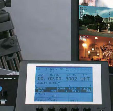
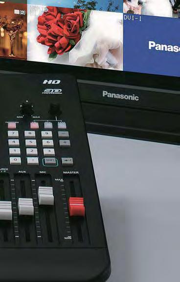

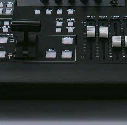


87 Live Relays with a Com Versatile HD


, PC (DVI-I) and HDMI (HD only) inputs, versatile digital effects, and comfortable Matrix Menu operation join with advanced")


 SDI (Multi-View) System Camera AG-HMR10 AG-HCK10G Professional Cameras Equipped with HDMI output AG-HMC150 series AG-HMC40 series SDI x 4")

, Program (PGM), and all sour ce images on a single monitor.")
88 pact, All-in-One, Easy-to-Use, Low-Cost System. /SD Multi-Format Use, and 3D Image Switching. The AG-HMX100 is a compact, all-in-one, digital AV mixer with a built-in HD/SD multi-format* 1 video switcher, audio mixer, frame synchronizer and digital effector. It serves as an audio/video switcher, adds a variety of effects, and transmits signals - all by itself. A Multi-View function displays all source images on a single monitor, while keeping the system configuration simple and clean. Users benefit from easy delivery, set-up and removal at event sites, as well as low-cost operation. Wide-ranging SDI (HD/SD), PC (DVI-I) and HDMI (HD only) inputs, versatile digital effects, and comfortable Matrix Menu operation join with advanced functions, such as control of Panasonic professional projectors,* 2 to configure a low-cost system that supports a wide variety of applications, from live relays and broadcasting to production. The AG-HMX100 can also operate as a 3D video switcher with dual SDI inputs.* 3 By combining it with several 3D cameras and 3D projectors, it can serve as a 3D live switching system for low-cost, easy-to-use, 3D image broadcasting and production systems. System Example (2D) Professional Cameras Equipped with SDI output PC LCD Monitor AG-HPX300 series AG-HPX370 series AG-HPX170 series DVI-I DVI-D (Multi-View) SDI (Multi-View) System Camera AG-HMR10 AG-HCK10G Professional Cameras Equipped with HDMI output AG-HMC150 series AG-HMC40 series SDI x 4 (HD/SD) HDMI x 2 (HD) or Composite Video x 2 (SD) AG-HMX100 DVI-D (PGM) /SDI (AUX*) RS-232C SDI (PGM) Projector Recorder picture simulated Consumer s Video Camera *Program OUT can be set by the menu. 1 HD /S D multi vi deo format compatibility.* Dig igit ital int er faces of SDI (HD/SD) input/output and HDMI (HD) input. DVI -I inp nput acc ccommodates both motion and still images from a PC. Mul ti -V ie w func tion displays Preview (PVW), Program (PGM), and all sour ce images on a single monitor. A wav ef orm monitor (WFM) is built-in, and source names and audio levels are supe ri mp osed on the monitor. Rem ot e co nt rol of power on/off and shutter on/off for the Panasonic projectors* 2. 3 Su ppor ts swi tchi ng of 3D images, using dual SDI inputs.* *1: Mixed operation of different video formats (1080i/720p, HD/SD and 50Hz/59.94Hz) is not possible. *2: Limited to models with an RS-232C interface. *3: Effects are not supported.

89 FUNCTIONS AND INTERFACES HD/SD Digital AV Mixer Functions HD/SD Multi-Format High-Quality Image Processing The AG-HMX100 supports 1080i/720p HD and SD images (see table below). A wipe pattern lets you switch between 16:9 and 4:3 aspect ratios. Full 4:2:2:4 digital component 12bit internal processing ensures broadcast-grade images. Supported Video Format Video Input Video Format HD (SDI/HDMI) SD (SDI/VIDEO) PC (DVI-I) 1080/59.94i 1080/50i 720/59.94p 720/50p 480/59.94i 576/50i 1080/60p 1920 x 1080 (60Hz) 1080/50p 1920 x 1080 (50Hz) SXGA 1280 x 1024 (60Hz) WXGA 1280 x 768 (60Hz) XGA 1024 x 768 (60Hz) * Mixed operation of different video formats (1080i/720p, HD/SD and 50Hz/59.94Hz) is not possible. PC (DVI-I) can be input to any system format, but it would be resized to match and displayed. 7 Video Inputs with PC Image Support and 6 Video Outputs 7 video inputs: SDI (HD/SD switchable) x 4 channels, HDMI (HD only/hdcp and VIERA Link not supported) or video (composite) x 2 channels, and a DVI-I input capable of inputting motion or still images from a PC. This provides up to 7 channels of video input. 6 video outputs: 4 SDI outputs (Program (PGM), Preview (PVW), Multipurpose (AUX), and Multi-View), and 2 DVI-D outputs (Program (PGM) and Multi-View). Transitions and Digital Effects Transitions: Over 100 wipe patterns and mixes combine with effects like chroma keying, luminance keying, DSK, and fading. M/E preview and DSK preview are also supported. Digital Effects: Built-in digital effects include mosaic, defocus, monocolor, still, strobe, multi-strobe, decay, paint, negative and mirror. Still, strobe and multi-strobe effects allow selection of field or frame displays.

, and mute. Level meter: Displayed as a Multi-View overlay on the LCD screen.")

90 Embedded Digital Audio and Analog Audio Mixing 10 audio inputs: Select up to 8 audio inputs from 4 SDI embedded audio inputs (L/R), 2 HDMI embedded audio inputs (L/R), and 4 XLR audio inputs (L/R). You can mix the 10 audio sources, including AUX input and MIC input, using a fader control. Audio output: SDI embedded audio is output from PGM, PVW, and AUX terminals, and has XLR (L/R) and pin terminal (L/R) analog outputs. Audio effects: Pan, 3 band equalizer, voice changer (pitch/level), and mute. Level meter: Displayed as a Multi-View overlay on the LCD screen. New Multi-View Function, Built-in Waveform Monitor The Multi-View function and Multi-View output terminal (SDI/DVI-D) provide a split display of the PVW, PGM, and all source images on a single screen. Displays of each of the input signal names and audio level meters can also be overlaid. The built-in Waveform Monitor (WFM) function displays the waveforms of video Y signals, allowing multichannel systems to be operated with a single monitor. Projector Control Function The power switch and shutter for Panasonic professional projectors can be turned on and off by RS-232C remote control. This allows convenient projector use during live events. AG-HMX100 Video DVI-D or SDI Control RS-232C Projector Functions for More Comfortable Operation Pattern preset: Up to 7 transition patterns and 6 key patterns can be directly registered, for retrieval with a single touch. Event memory: Records the setting conditions of the effects. Over 100 settings can be stored in memory, and instantly retrieved with pattern numbers. Key learn: Records and retrieves the key frame settings (positions/levels/ modifiers) and reproduces animation effects. Up to 20 patterns can be stored in memory, with a maximum of 20 frames per pattern. Joystick controller: Enables intuitive operation of effect position setting and color correction/color selection. Numerical keypad: For setting numbers, such as pattern numbers. Versatile Interfaces Tally: Outputs support up to eight input sources. Ideal for live relays. GPI: Visual effects including key/transition, downstream key, and fading can be externally controlled with GPI trigger signal inputs. AUX output: Select from PGM/PVW/Multiview output signals, or an SDI/HDMI input through-out signal. Multi-View Screen (simulated image) Matrix Menu and Rotary Switch The large LCD panel allows easy monitoring of system status. The 5 column, 3 row matrix menu automatically displays setting items according to the operating status, so the relevant settings can be quickly checked or changed. Settings that have a large number of selections can also be quickly and intuitively displayed and set by using the rotary switch. This provides easy, comfortable settings control for the AG-HMX100's many diverse functions. Power-Saving Eco Design Power-saving design: HD images are supported, while power consumption is decreased by 15% compared to our previous SD-Type AG-MX70 model. Power management: This function automatically switches the power off when there is no input or operation for a preset period of time. Can be powered on with a secondary switch on the control panel. AG-HMX100 Rear

 3D Camera (B) specification 1: Side-By-Side 3D Camera (A) 3D Camera (B) 3D Camera (A) 3D Camera (B) 3D Camera (C) 3D Camera (D) SDI1 Left Eye Signal SDI2 Right Eye Signal SDI3 Left Eye Signal SDI4")

91 FULL HD 3D PRODUCTION SYSTEM Professional HD 3D Production System Functions A Professional HD 3D Production System The AG-HMX100 Digital AV Mixer fully supports the Panasonic shift toward 3D world. Combined with the Panasonic AG-3DA1 Integrated Twin-Lens 3D Camera Recorder, and the 3D-compatible BT-3DL2550 Professional LCD Video Monitor, which lets you view 3D footage on-site, this professional HD 3D production system makes it easy to produce and transmit highquality 3D images. specification 1: Simultaneous 3D Camera (A) (AG-3DA1 etc.) 3D Camera (B) specification 1: Side-By-Side 3D Camera (A) 3D Camera (B) 3D Camera (A) 3D Camera (B) 3D Camera (C) 3D Camera (D) SDI1 Left Eye Signal SDI2 Right Eye Signal SDI3 Left Eye Signal SDI4 Right Eye Signal SDI1 Left Eye Signal SDI2 Right Eye Signal SDI3 Left Eye Signal SDI4 Right Eye Signal specification 1: Simultaneous SDI1 Left Eye Signal SDI2 Left Eye Signal SDI3 Left Eye Signal SDI4 Left Eye Signal SDI1 Right Eye Signal SDI2 Right Eye Signal SDI3 Right Eye Signal SDI4 Right Eye Signal * No effect, switching only. * No effect, switching only. EXT-REF EXT-REF RS-232C * No effect, switching only. Supported signals: 1080/59.94i, 1080/50i, 720/59.94p, 720/50p, 1080/23.98psf Switching specifications in 3D mode Supports Switched Transmission of 3D Camera Images The AG-HMX100 can operate as a 3D video switcher with dual SDI signal inputs from 3D cameras. It comes with two pairs of inputs and one pair of outputs for 3D video signals. It is possible to configure a 3D live switching system by combining it with several 3D cameras and 3D projection systems. Both Simul and Side-by-Side 3D output methods are supported. When two AG-HMX100 units are connected, they can serve as a 3D video switcher for up to four 3D cameras. *Only the switcher function operates. Effects such as ME cannot be used. Other functions, such as Multi-View, WFM, and title mix, are not supported. For details, visit the 3D special site. ( 3D Program Output SDI PGM Left Eye Signal SDI MULTI-VIEW Right Eye Signal DVI-D PGM Left Eye Signal DVI-D MULTI-VIEW Right Eye Signal 3D Program Output SDI PGM Side-By-Side Signal SDI MULTI-VIEW Side-By-Side Signal DVI-D PGM Side-By-Side Signal DVI-D MULTI-VIEW Side-By-Side Signal 3D Program Output SDI PGM Left Eye Signal SDI MULTI-VIEW Left Eye Signal DVI-D PGM Left Eye Signal DVI-D MULTI-VIEW Left Eye Signal SDI PGM Right Eye Signal SDI MULTI-VIEW Right Eye Signal DVI-D PGM Right Eye Signal DVI-D MULTI-VIEW Right Eye Signal or 3D LCD Video Monitor BT-3DL2550 3D Projection Systems BT-3DL2550 3D VIERA BT-3DL2550 BT-3DL2550 3D Projection Systems 3D Projection Systems *3D Plasma Display is scheduled for release in Autumn of Please refer to the latest 3D Plasma Display Information at Panasonic website. < > or or or 3D Projection Systems 3D Plasma Display* 3D Projection Systems 3D Projection Systems

 Synchronization signal 3D Projection Systems (DLP Projector x2) Screen AG-3DA1 Digital AV Mixer AG-HMX100 Polarized glasses 3D x 4-Input System This 4-input switching system creates 3D")
92 picture simulated 3D system configuration example 3D Live Display System This system produces 3D live images by using two AG-3DA1 Integrated Twin-Lens 3D Camera Recorders and switching the image transmission for display on a professional DLP projector. It is also possible to monitor the PGM image with the BT-3DL2550 3D-Compatible LCD Monitor. Integrated Twin-lens 3D Camera Recorder AG-3DA1 HD SDI (L) HD SDI (R) HD SDI (L) HD SDI (R) HD SDI (L) Synchronization signal HD SDI (R) 3D LCD Video Monitor BT-3DL2550 Polarized glasses HD SDI (L) HD SDI (R) Synchronization signal 3D Projection Systems (DLP Projector x2) Screen AG-3DA1 Digital AV Mixer AG-HMX100 Polarized glasses 3D x 4-Input System This 4-input switching system creates 3D content by using two P2 Mobile units to combine the images from three 3D cameras. When two AG-HMX100 units are connected, they can serve as a 3D video switcher for up to four 3D cameras. Dynamic 3D live videos can be displayed on a large screen for high-brightness, high-contrast 3D projection by using two professional DLP projectors. Memory Card Portable-Recorder AJ-HPM200 Synchronization signal RS-422A Controller RS-422A Synchronization signal P2 Card (Rch video signal) HD SDI (R) AJ-HPM200 AG-3DA1 AG-3DA1 P2 Card (Lch video signal) HD SDI (L) HD SDI (L) HD SDI (R) Integrated Twin-lens 3D Camera Recorder AG-3DA1 HD SDI (L) HD SDI (R) HD SDI (L) HD SDI (R) HD SDI (L) Synchronization signal RS-232C Polarized glasses HD SDI (R) Digital AV Mixer AG-HMX100 Synchronization signal AG-HMX100 3D LCD Video Monitor BT-3DL2550 Synchronization signal HD SDI (L) HD SDI (R) 3D Projection Systems s (DLP Projector x2) Synchronization signal HD SDI (L) HD SDI (R) Screen Screen Polarized glasses
Operating Instructions
 Operating Instructions SDI Input board Model No. AV-HS04M1 РУССКИЙ FRANÇAIS DEUTSCH ENGLISH ESPAÑOL ITALIANO Before operating this product, please read the instructions carefully and save this manual for
HD Digital Set-Top Box Quick Start Guide
 HD Digital Set-Top Box Quick Start Guide Eagle Communications HD Digital Set-Top Box Important Safety Instructions WARNING TO REDUCE THE RISK OF FIRE OR ELECTRIC SHOCK, DO NOT EXPOSE THIS PRODUCT TO RAIN
Evolution Digital HD Set-Top Box Important Safety Instructions
 Evolution Digital HD Set-Top Box Important Safety Instructions 1. Read these instructions. 2. Keep these instructions. 3. Heed all warnings. 4. Follow all instructions. 5. Do not use this apparatus near
CAUTION RISK OF ELECTRIC SHOCK NO NOT OPEN
 Evolution Digital HD Set-Top Box Important Safety Instructions 1. Read these instructions. 2. Keep these instructions. 3. Heed all warnings. 4. Follow all instructions. 5. Do not use this apparatus near
 Register your product and get support at www.philips.com/welcome SWS3435S/27 SWS3435H/37 EN User manual Contents 1 Important 4 Safety 4 English 2 Your SWS3435 6 Overview 6 3 Installation 7 Connect the
2.0 Wall Mount TV Soundbar Instruction Manual
 8010275 2.0 Wall Mount TV Soundbar Instruction Manual Read all of the instructions before using this soundbar and keep the manual in a safe place for future reference. Safety Information CA UT IO N RISK
HD Digital MPEG2 Encoder / QAM Modulator
 HD Digital MPEG2 Encoder / QAM Modulator HDMI In QAM Out series Get Going Guide ZvPro 800 Series is a one or two-channel unencrypted HDMI-to-QAM MPEG 2 Encoder / QAM Modulator, all in a compact package
USER MANUAL. 27 Full HD Widescreen LED Monitor L27ADS
 USER MANUAL 27 Full HD Widescreen LED Monitor L27ADS TABLE OF CONTENTS 1 Getting Started 2 Control Panel/ Back Panel 3 On Screen Display 4 Technical Specs 5 Care & Maintenance 6 Troubleshooting 7 Safety
USER MANUAL. 22" Class Slim HD Widescreen Monitor L215DS
 USER MANUAL 22" Class Slim HD Widescreen Monitor L215DS TABLE OF CONTENTS 1 Getting Started Package Includes Installation 2 Control Panel / Back Panel Control Panel Back Panel 3 On Screen Display 4 Technical
HD Digital MPEG2 Encoder / QAM Modulator Get Going Guide
 series HD Digital MPEG2 Encoder / QAM Modulator Get Going Guide HDb2640 HDb2620 HDb2540 HDb2520 The HDbridge 2000 Series is a combination HD MPEG 2 Encoder and frequency-agile QAM Modulator, all in a 1RU
HD Digital MPEG2 Encoder / QAM Modulator
 HD Digital MPEG2 Encoder / QAM Modulator YPrPb VGA In QAM Out series Get Going Guide ZvPro 600 Series is a one or two-channel Component or VGA-to-QAM MPEG 2 Encoder/ Modulator, all in a compact package
ZvBox 150. HD video distribution over COAX Get Going Guide
 ZvBox 150 HD video distribution over COAX Get Going Guide ZvBox 150 is an HD MPEG 2 Encoder and frequency agile QAM Modulator. It allows you to convert any HD video source, Component or RGB (VGA), in real
Register your product and get support at SDV5122/27. EN User manual
 Register your product and get support at www.philips.com/welcome SDV5122/27 User manual Contents 1 Important 4 Safety 4 Notice for USA 5 Notice for Canada 5 Recycling 6 English 2 Your SDV5122 7 Overview
28 4K LED monitor. User Manual M284K
 28 4K LED monitor User Manual M284K CONTENTS Safety Information... 2 What s included..... 4 Getting Started....... 8 Troubleshooting.... 14 Specification.... 15 2 of 15 SAFETY INFORMATION Read these instructions
Introduction. Important Safety Instructions
 Introduction Congratulations on purchasing your Eviant Portable Digital TV. On June 12, 2009 the conversion to digital television broadcasting will be complete all throughout the United States and Puerto
ATTACHING & REMOVING THE BASE
 TV53DB ATTACHING & REMOVING THE BASE 1. To install or remove the neck, screw in or remove the 4 screws indicated in the picture. 2. To install the base, place the display unit flat on a table. Afterwards
USER MANUAL. 27 Full HD Widescreen LED Monitor L270E
 USER MANUAL 27 Full HD Widescreen LED Monitor L270E TABLE OF CONTENTS 1 Getting Started 2 Control Panel/ Back Panel 3 On Screen Display 4 Technical Specs 5 Care & Maintenance 6 Troubleshooting 7 Safety
AUTO - SCANNING WITH DIGITAL CONTROL LCD COLOR MONITOR FS-L1903C. User manual (Rev.01) SMITHS HEIMANN
 SMITHS HEIMANN") AUTO - SCANNING WITH DIGITAL CONTROL LCD COLOR MONITOR FS-L1903C User manual (Rev.01) SMITHS HEIMANN www.smithsdetection.com Table of Contents Safety Instructions... 5 Accessories... 8 Power Connections...
AUTO - SCANNING WITH DIGITAL CONTROL LCD COLOR MONITOR FS-L1903C User manual (Rev.01) SMITHS HEIMANN www.smithsdetection.com Table of Contents Safety Instructions... 5 Accessories... 8 Power Connections...
TS2.8 Sub OWNER S MANUAL
 TS2.8 Sub OWNER S MANUAL TS2.8 Sub CONTENTS IMPORTANT SAFETY INSTRUCTIONS 03 WARNINGS 03 FUSE PROTECTION 04 WARNING: STRONG MAGNETIC FIELD 04 EMC / EMI 04 ECODESIGN STANDBY POWER CONSUMPTION 04 WARRANTY
ZVOX AccuVoice TV Speaker Model AV203
 ZVOX AccuVoice TV Speaker Model AV203 SETUP & OPERATION www.zvoxaudio.com READ THIS FIRST Important Safety Instructions For ZVOX Audio System WARNING TO PREVENT FIRE OR SHOCK HAZARD, DO NOT EXPOSE THIS
USER MANUAL Full HD Widescreen LED Monitor L215ADS
 USER MANUAL 21.5 Full HD Widescreen LED Monitor L215ADS TABLE OF CONTENTS 1 Getting Started 2 Control Panel/ Back Panel 3 On Screen Display 4 Technical Specs 5 Care & Maintenance 6 Troubleshooting 7 Safety
Technical Specifications
 INSTALLATION SHEET AND OPERATORS MANUAL General Description: The is a mixer/preamplifier that includes 6 channels that each include a microphone input at screw terminals and an aux input at an RCA jack.
USER MANUAL Full HD Widescreen LED Monitor L215IPS
 USER MANUAL 21.5 Full HD Widescreen LED Monitor L215IPS TABLE OF CONTENTS 1 Getting Started 2 Control Panel/ Back Panel 3 On Screen Display 4 Technical Specs 5 Care & Maintenance 6 Troubleshooting 7 Safety
27'' Full HD LED Monitor KALED27MONSC Quick Start Guide
 Safety Warnings 27'' Full HD LED Monitor KALED27MONSC Quick Start Guide TO REDUCE THE RISK OF ELECTRIC SHOCK, DO NOT REMOVE ANY COVERS (OR BACKINGS). NO USER SERVICEABLE PARTS ARE INSIDE. REFER ALL SERVICING
Installation Manual VIP 1003
 Installation Manual VIP 1003 We Caring for the Environment by Recycling When you see this symbol on a Motorola product, do not dispose of the product with residential or commercial waste. Recycling your
USER MANUAL Full HD Widescreen LED Monitor L236VA
 USER MANUAL 23.6 Full HD Widescreen LED Monitor L236VA TABLE OF CONTENTS 1 Getting Started 2 Control Panel/ Back Panel 3 On Screen Display 4 Technical Specs 5 Care & Maintenance 6 Troubleshooting 7 Safety
ZVOX AccuVoice TV Speaker Model AV203
 ZVOX AccuVoice TV Speaker Model AV203 SETUP & OPERATION www.zvoxaudio.com 2 ZVOX AccuVoice TV Speaker Setup & Operation READ THIS FIRST Important Safety Instructions For ZVOX Audio System WARNING TO PREVENT
9.7-INCH VALUE LED MONITOR
 9.7-INCH VALUE LED MONITOR USER MANUAL Please read this manual thoroughly before use, and keep it handy for future reference. SAFETY INSTRUCTION. 2 ~ 3 CAUTIONS... 4 FCC RF INTERFERENCE STATEMENT... 5
17 19 PROFESSIONAL LCD COLOUR MONITOR ART
 17 19 PROFESSIONAL LCD COLOUR MONITOR ART. 41657-41659 Via Don Arrigoni, 5 24020 Rovetta S. Lorenzo (Bergamo) http://www.comelit.eu e-mail:export.department@comelit.it WARNING: TO REDUCE THE RISK OF FIRE
MON8-1/SDI 1U 8-Channel SDI Digital Multi-Display Video Monitor
 MON8-1/SDI 1U 8-Channel SDI Digital Multi-Display Video Monitor (Document P/N 821626, Rev-A) with Eight Backlit 1.8" LCD Displays, Eight SDI Video Inputs, Eight SDI Re-Clocked Outputs, and Eight CVBS (Analog)
Reveal 402 / 502 / 802. English Manual
 Reveal 402 / 502 / 802 English Manual English manual English manual Important safety instructions 1. Read these instructions. 2. Keep these instructions. 3. Heed all warnings. 4. Follow all instructions.
Monochrome Video Monitors
 Instructions for Use Monochrome Video Monitors En F D E NL I LTC 2009 LTC 2012 LTC 2017 Philips Communication & Security Systems GB F D E NL I Instructions for Use...1.1 Mode d emploi...2.1 Bedienungsanleitung...3.1
USER MANUAL. 27" 2K QHD LED Monitor L27HAS2K
 USER MANUAL 27" 2K QHD LED Monitor L27HAS2K TABLE OF CONTENTS 1 Getting Started 2 Control Panel/ Back Panel 3 On Screen Display 4 Technical Specs 5 Troubleshooting 6 Safety Info & FCC warning 1 GETTING
LED TV MODEL NO.: NE22K5BG. Please read this manual carefully before installing and operating the TV. Keep this manual handy for further reference
 LED TV USER MANUAL MODEL NO.: NE22K5BG IMPORTANT Please read this manual carefully before installing and operating the TV. Keep this manual handy for further reference Table Of Contents Preparations Guide
PowerWave PW1A Panel and Wall-Mount Models Installation Guide AV69006-XXX
 PowerWave PW1A Panel and Wall-Mount Models Installation Guide 8820-00063 AV69006-XXX Table of Contents Table of Contents sections 1 2 3 4 5 6 7 8 9 1. Introduction............................................
Q-TV2. User Manual. for Screens
 Q-TV2 User Manual for 30-42 Screens Contents Introduction 02 Safety Guidelines 03 Getting started 03 Potential Uses 04 Carton Contents 05 Q-TV2 Controls 05 Remote Fixings 06 Fixing Rails 07 Fitting Q-TV2
USER MANUAL. 28" 4K Ultra HD Monitor L28TN4K
 USER MANUAL 28" 4K Ultra HD Monitor L28TN4K TABLE OF CONTENTS 1 Getting Started 2 Control Panel/ Back Panel 3 On Screen Display 4 Technical Specs 5 Care & Maintenance 6 Troubleshooting 7 Safety Info &
guestlink PowerWave PW4A Panel and Wall-Mount Models Installation Guide AV69102-XXX-XXX
 guestlink PowerWave PW4A Panel and Wall-Mount Models Installation Guide 8820-00291 AV69102-XXX-XXX Table of Contents Table of Contents sections 1 2 3 4 5 6 7 8 9 1. Introduction............................................
DCL9AW. User Manual. English
 DCL9AW User Manual English PRECAUTIONS Information for users applicable in European Union countries 1 Information for users applicable in United States of America 1 Installation 1 Power connection 1 Maintenance
Wired to Wireless Camera Converter
 Wired to Wireless Camera Converter Instruction Manual English Version 1.0 MODEL: WL401BNC www.lorexcctv.com Copyright (c) 2006 LOREX Technology Inc. Thank you for purchasing the 2.4 GHz Wireless Camera
MON8-1 1U 8-Channel Multi-Display Video Monitor
 MON8-1 1U 8-Channel Multi-Display Video Monitor with Eight Backlit 1.75" LCD Displays, Eight CVBS Video Inputs, and Eight Loop-through Outputs Document P/N 821568 Rev-A User Manual CONTENTS Title and Contents...
PLL1920M LED LCD Monitor
 PLL1920M LED LCD Monitor USER'S GUIDE www.planar.com Content Operation Instructions...1 Safety Precautions...2 First Setup...3 Front View of the Product...4 Rear View of the Product...5 Installation...6
Electro Magnetic Compatibility (EMC) Warning. Important notes for users in the U.K. FCC declaration. Caution. Fuse
 Warning. Important notes for users in the U.K. FCC declaration. Caution. Fuse") Warning: to prevent fire or shock hazard, do not expose camera or monitor to rain or moisture. The lightning flash with arrowhead symbol, within a triangle, is intended to alert the user to the presence
Warning: to prevent fire or shock hazard, do not expose camera or monitor to rain or moisture. The lightning flash with arrowhead symbol, within a triangle, is intended to alert the user to the presence
DM-1CH SD DVB-T MODULATOR INSTRUCTION MANUAL
 DM-1CH SD DVB-T MODULATOR INSTRUCTION MANUAL 2. Caution Statements and Table of Contents Table of Contents 2. Caution Statements and Table of contents 3. Important Safety Instructions 4. Important Safety
17 /19. User's Manual
 17 /19 Color TFT LCD Monitor User's Manual Version: 03 * All other brand names are registered trademarks of their respective owners Table of Contents Important Safety Instructions FCC Regulation Class
PLL2210MW LED Monitor
 PLL2210MW LED Monitor USER'S GUIDE www.planar.com Content Operation Instructions...1 Safety Precautions...2 First Setup...3 Front View of the Product...4 Rear View of the Product...5 Quick Installation...6
2.4 GHz WIRELESS VIDEO SENDER SYSTEM MODEL: VS6234
 2.4 GHz WIRELESS VIDEO SENDER SYSTEM MODEL: VS6234 Please read this manual thoroughly before operating this system OPERATING INSTRUCTIONS 03/02 1 SAFETY INSTRUCTIONS CAUTION! RISK OF ELECTRIC SHOCK. DO
PL2410W LCD Monitor USER'S GUIDE.
 PL2410W LCD Monitor USER'S GUIDE www.planar.com Content Operation Instructions...1 Safety Precautions...2 First Setup...3 Front View of the Product...4 Rear View of the Product...5 Quick Installation...6
Winmate Communication INC.
 20.1 Military Grade Display Model: R20L100-RKA2ML User s Manual Winmate Communication INC. May, 2011 1 IMPORTANT SAFETY INSTRUCTIONS Please read these instructions carefully before using the product and
Disclaimer. Trademarks. Copyright. Contact Us Control4 Corporation S. Election Road Salt Lake City, UT USA
 Disclaimer Trademarks Copyright Control4 makes no representations or warranties with respect to this publication, and specifically disclaims any express or implied warranties of merchantability or fitness
Multi-Channel Passive Transceiver Hubs Installation Sheet
 GE Security Multi-Channel Passive Transceiver Hubs Installation Sheet Introduction GE Security Multi-Channel Passive Transceiver Hubs transmit or receive baseband video signals over unshielded twisted
MON3-2W/HR MON4-2W/HR (Document P/N Rev-B)
") MON3-2W/HR MON4-2W/HR (Document P/N 821647 Rev-B) HD/SDI High-Res Video Monitors with 4.3" High-Resolution LCD Video Displays, Selectable 16:9 or 4:3 Aspect Ratio, SDI or HD-SDI Inputs and Buffered/Equalized
MON3-2W/HR MON4-2W/HR (Document P/N 821647 Rev-B) HD/SDI High-Res Video Monitors with 4.3" High-Resolution LCD Video Displays, Selectable 16:9 or 4:3 Aspect Ratio, SDI or HD-SDI Inputs and Buffered/Equalized
DDW36C Advanced Wireless Gateway - Safety and Installation Product Insert. Federal Communications Commission (FCC) Interference Statement
 Interference Statement") DDW36C Advanced Wireless Gateway - Safety and Installation Product Insert Federal Communications Commission (FCC) Interference Statement This equipment has been tested and found to comply with the limits
DDW36C Advanced Wireless Gateway - Safety and Installation Product Insert Federal Communications Commission (FCC) Interference Statement This equipment has been tested and found to comply with the limits
 Register your product and get support at www.philips.com/welcome SWW1810 User manual 3 Contents 1 Important 4 Safety 4 English 2 Your Wireless HD AV Connect 6 What is in the box 6 3 Overview 7 The transmitter
55" Curved Ultra HD LED TV User s Guide for Model TU5587B v For the most up-to-date version of this User s Guide, go to
 55" Curved Ultra HD LED TV User s Guide for Model TU5587B v1922-01 For the most up-to-date version of this User s Guide, go to www.gpx.com Safety Instructions & Warnings CAUTION RISK OF ELECTRIC SHOCK
Check our knowledge base at
 USER MANUAL Check our knowledge base at www.paralinx.net/support Copyright 2015 Paralinx LLC All Rights Reserved TABLE OF CONTENTS 1 Important Notice 10 LCD Screen 2 Safety Instructions 11 Indicators 3
Utility Amplifier GA6A Model
 Utility Amplifier GA6A Model Installation and Use Manual 2004 Bogen Communications, Inc. All rights reserved. Specifications subject to change without notice. 54-5757-03D 1503 NOTICE: Every effort was
LCD VALUE SERIES (32 inches)
") LCD VALUE SERIES (32 inches) http://www.orionimages.com All contents of this document may change without prior notice, and actual product appearance may differ from that depicted herein 1. SAFETY INSTRUCTION
LCD VALUE SERIES (32 inches) http://www.orionimages.com All contents of this document may change without prior notice, and actual product appearance may differ from that depicted herein 1. SAFETY INSTRUCTION
User Manual MODEL: KK1500-TR. Touch Display LCD Monitor. Installation Guide. 15 Resistive Touch LCD Monitor
 Touch Display LCD Monitor User Manual Installation Guide 15 Resistive Touch LCD Monitor MODEL: KK1500-TR i-tech Company LLC TOLL FREE: (888) 483-2418 EMAIL: info@itechlcd.com WEB: www.itechlcd.com User
23-INCH WIDE TFT-LED MONITOR
 23-INCH WIDE TFT-LED MONITOR USER MANUAL Please read this manual thoroughly before use, and keep it handy for future reference. SAFETY INSTRUCTION. 2 ~ 3 CAUTIONS... 4 FCC RF INTERFERENCE STATEMENT...
VIZIO. QUICK START GUIDE Model: E390-B1
 VIZIO QUICK START GUIDE Model: E390-B1 IMPORTANT SAFETY INSTRUCTIONS Your TV is designed and manufactured to operate within defined design limits. Misuse may result in electric shock or fire. To prevent
E325 Series User Guide
 E325 Series User Guide PACKAGE CONTENTS SCEPTRE Display x 1 Display Base x 1 Thick Threaded Screws x 3 Thin Threaded Screws x 4 Circular Metal Plate x 1 Black Plastic Ring x 1 Power Cord x 1 (Attached)
HDMI 5x1 Switch B-240-HDSWTCH-5X1 INSTALLATION MANUAL
 HDMI 5x1 Switch B-240-HDSWTCH-5X1 INSTALLATION MANUAL IMPORTANT SAFETY INSTRUCTIONS To reduce the risk of fire or electric shock, read and follow all instructions and warnings in this manual. Keep this
18.5/21.5-INCH WIDE TFT-LCD MONITOR USER MANUAL
 18.5/21.5-INCH WIDE TFT-LCD MONITOR USER MANUAL Please read this manual thoroughly before use, and keep it handy for future reference. SAFETY INSTRUCTION. 2 ~ 3 CAUTIONS... 4 FCC RF INTERFERENCE STATEMENT...
4 PORT HDMI SWITCH
 4 PORT HDMI SWITCH 1518896 IMPORTANT SAFEGUARDS OF HDMI SWITCH PRODUCTS PLEASE READ CAREFULLY THE FOLLOWING SAFEGUARDS THAT ARE APPLICABLE TO YOUR EQUIPMENT 1. Read instructions - All the safety and operating
INSTALLATION MANUAL VIP 1903 / VIP 1903 T VIP 1963 / VIP 1963 T
 INSTALLATION MANUAL VIP 1903 / VIP 1903 T VIP 1963 / VIP 1963 T We Declaration of Conformity Motorola Mobility, Inc. 101 Tournament Drive Horsham Pennsylvania 19044 USA declare under our sole responsibility
E246 Series User Guide
 E246 Series User Guide IMPORTANT SAFETY INSTRUCTIONS Electricity is used to perform many useful functions, but it can also cause personal injuries and property damage if improperly handled. This product
Congratulations on purchasing your Eviant Portable Digital TV.
 Introduction Congratulations on purchasing your Eviant Portable Digital TV. On June 12, 2009 the conversion to digital television broadcasting will be complete all throughout the United States and Puerto
E246 Series User Guide
 E246 Series User Guide PACKAGE CONTENTS SCEPTRE Display x 1 Display Base x 1 Display Neck x 1 Screws x 6 (ST3 x 10mm) Warranty Card x 1 Power Cord x 1 (Attached) Display Remote Control (AAA Batteries included)
USER S MANUAL CCTV LED MONITOR MODEL: ADE-117N1 ADE-119N1 ADE-118W1 ADE-121W1 ADE-124W Atherton Electronics Corp. All rights reserved.
 USER S MANUAL CCTV LED MONITOR MODEL: ADE-117N1 ADE-119N1 ADE-118W1 ADE-121W1 ADE-124W1 2015 Atherton Electronics Corp. All rights reserved. TABLE OF CONTENTS FCC information -------------------------------------------------------------------
U65 Series User Guide
 U65 Series User Guide IMPORTANT SAFETY INSTRUCTIONS Electricity is used to perform many useful functions, but it can also cause personal injuries and property damage if improperly handled. This product
User Manual MODEL: KKF1500-PCAP. True FLAT P-CAP LCD Monitor. Installation Guide. 15 True FLAT P-CAP Touch LCD Monitor
 True FLAT P-CAP LCD Monitor User Manual Installation Guide 15 True FLAT P-CAP Touch LCD Monitor MODEL: KKF1500-PCAP i-tech Company LLC TOLL FREE: (888) 483-2418 EMAIL: info@itechlcd.com WEB: www.itechlcd.com
35 INCH CURVED QHD LED MONITOR
 35 INCH CURVED QHD LED MONITOR eiq-35cmuwq60gafs Thank you for choosing electriq Please read this user manual before using this monitor and keep it safe for future reference. Visit our page www.electriq.co.uk
Full High Definition LCD TV USER MANUAL
 1080p3 LCD TV Full High Definition LCD TV 1080p3 USER MANUAL Important Safety Precautions Important Safety Precautions 1 CAUTION RISK OF ELECTRIC SHOCK DO NOT OPEN This symbol indicates important instructions
 Register your product and get support at www.philips.com/welcome SWW1890 User manual Contents 1 Important 4 Safety 4 English 2 Your Philips Wireless HD Net Connect 5 What is in the box 5 3 Overview 6
PXL2760MW LED LCD Monitor
 PXL2760MW LED LCD Monitor USER'S GUIDE www.planar.com Content Operation Instructions...1 Safety Precautions...2 Package Overview...3 First Setup...4 Front View of the Product...5 Rear View of the Product...6
KD-CTCA3. Component Video to VGA Adapter
 KD-CTCA3 Component Video to VGA Adapter Model KD-CTCA3 KD-CTCA3 Component Video to VGA Adapter Model KD-CTCA3 Component Video (YPrPb) input to VGA Video (RGBHV) output Video Adapter with added features
PH-1. Italian MM & MC Phono Preamplifier OWNER S MANUAL
 PH-1 Italian MM & MC Phono Preamplifier OWNER S MANUAL IMPORTANT SAFETY INFORMATION CAUTION: TO REDUCE THE RISK OF ELECTRIC SHOCK, DO NOT REMOVE COVER (OR BACK). NO USER-SERVICEABLE PARTS INSIDE. REFER
By CHANNEL VISION. Flush Mount Amplifier A0350
 Spkrs Local In IR In 24VDC A0350 10 The A0350 can be used with Channel Vision s CAT5 audio hubs to provide a powerful 50Watts per channel in the listening zone. Alternatively, the A0350 can be added to
MONOPRICE. 27" UHD IPS 4K Ultra Slim Aluminum Monitor. Quick User's Guide P/N 24658
 MONOPRICE 27" UHD IPS 4K Ultra Slim Aluminum Monitor P/N 24658 Quick User's Guide SAFETY WARNINGS AND GUIDELINES Please read this entire manual before using this device, paying extra attention to these
Model 1606 Super. User Manual
 Model 1606 Super User Manual All contents c Absara Audio LLC 2014 1. Important Safety Information The triangle surrounding an exclamation mark alerts users to the presence of important warnings or information.
FD Trinitron Colour Television
 R 4-205-569-32(1) FD Trinitron Television Instruction Manual GB KV-14LM1U 2000 by Sony Corporation NOTICE FOR CUSTOMERS IN THE UNITED KINGDOM A moulded plug complying with BS1363 is fitted to this equipment
1812R Blues King 12. User Manual
 1812R Blues King 12 User Manual All contents c Absara Audio LLC 2018 1. Important Safety Information The triangle surrounding an exclamation mark alerts users to the presence of important warnings or information.
Content. User s Manual 3. Owner s Manual Ver. 1.1 / June Introduction...4. Mytek Package Content Features...
 Owner s Manual User s Manual 3 Content Owner s Manual Ver. 1.1 / June 2018 Mytek 2017 The Brooklyn AMP firmware can be easily updated via Mytek USB Control Panel. As the firmware is updated, Mytek will
DisplayPort Extender over 2 LC Fibers
 DisplayPort Extender over 2 LC Fibers Audio 3GSDI Embedder EXT-DP-CP-2FO User Manual Release A2 DisplayPort Extender over 2 LC Fibers Important Safety Instructions 1. Read these instructions. 2. Keep these
SKYPLAY-MX Installation and Operation Guide
 SKYPLAY-MX Installation and Operation Guide Rev 130412 Important Safety Instructions Please completely read and verify you understand all instructions in this manual before operating this equipment. Keep
PLL2710W LED LCD Monitor
 PLL2710W LED LCD Monitor USER'S GUIDE www.planar.com Content Operation Instructions...1 Safety Precautions...2 Package Overview...3 First Setup...4 Front View of the Product...5 Rear View of the Product...6
BP2-MM MM Phono Preamplifier Owner s Manual
 BP2-MM MM Phono Preamplifier Owner s Manual Important Safety Instructions The lightning flash with arrowhead symbol within an equilateral triangle, is intended to alert the user to the presence of un-insulated
X50 Series User Guide
 X50 Series User Guide IMPORTANT SAFETY INSTRUCTIONS Electricity is used to perform many useful functions, but it can also cause personal injuries and property damage if improperly handled. This product
VIZIO. QUICK START GUIDE Model: E500i-B1E
 VIZIO QUICK START GUIDE Model: E500i-B1E IMPORTANT SAFETY INSTRUCTIONS Your TV is designed and manufactured to operate within defined design limits. Misuse may result in electric shock or fire. To prevent
SAFETY WARNINGS AND GUIDELINES
 SAFETY WARNINGS AND GUIDELINES Please read this manual thoroughly, paying extra attention to these safety warnings and guidelines: Do not expose this monitor to water or moisture of any kind. Do not handle
VIZIO MODELS. n E191VA n E221VA QUICK START GUIDE HD PICTURE SLIM DESIGN LED FULL USER MANUAL AVAILABLE AT VIZIO.COM
 MODELS n E191VA n E221VA VIZIO QUICK START GUIDE HD PICTURE SLIM DESIGN LED FULL USER MANUAL AVAILABLE AT VIZIO.COM IMPORTANT SAFETY INSTRUCTIONS Your TV is designed and manufactured to operate within
HID-C10 Important Information Guide
 HID-C10 Important Information Guide Owner s Record The model number and serial number are located on the bottom of the unit. Record the model and serial numbers in the space provided here and keep it in
USER MANUAL DUX-TX DUX-RX HDMI EXTENDER
 USER MANUAL DUX-TX DUX-RX HDMI EXTENDER Table of Contents Important Safety Instructions...03 Introduction...04 Features...04 Packing List...05 Specifications...06 DUX-TX Transmitter...06 DUX-RX Receiver...07
VIZIO. QUICK START GUIDE Model: E280-A1
 VIZIO QUICK START GUIDE Model: E280-A1 IMPORTANT SAFETY INSTRUCTIONS Your TV is designed and manufactured to operate within defined design limits. Misuse may result in electric shock or fire. To prevent
Personal Q Guide for VENUE Systems
 Personal Q Guide for VENUE Systems Version 1.0 Digidesign 2001 Junipero Serra Boulevard Daly City, CA 940-3886 USA tel: 650 731 6300 fax: 650 731 6399 Technical Support (USA) tel: 650 731 6100 fax: 650
VIZIO MODELS E320AR E420AR QUICK START GUIDE FULL USER MANUAL AVAILABLE AT VIZIO.COM
 MODELS E320AR E420AR VIZIO QUICK START GUIDE FULL USER MANUAL AVAILABLE AT VIZIO.COM IMPORTANT SAFETY INSTRUCTIONS Your TV is designed and manufactured to operate within defined design limits. Misuse may
User Manual High Definition Digital Set Top Box DVBT9070 Please read this User Manual carefully to ensure proper use of this product and keep this man
 User Manual High Definition Digital Set Top Box DVBT9070 Please read this User Manual carefully to ensure proper use of this product and keep this manual for future reference. Important Safety Instructions
VIZIO. QUICK START GUIDE Model: E650i-A2
 VIZIO QUICK START GUIDE Model: E650i-A2 IMPORTANT SAFETY INSTRUCTIONS Your TV is designed and manufactured to operate within defined design limits. Misuse may result in electric shock or fire. To prevent
It will cause malfunction if the monitor is operating with unspecified power supply
 User Manual / Installation Guide Model No. PTM-1525R/RT Warning! It will cause malfunction if the monitor is operating with unspecified power supply unit or incorrect power voltage. Do not exposure this