Logic Analysis Basics
|
|
|
- Susan Webster
- 5 years ago
- Views:
Transcription
1 Logic Analysis Basics September 27, 2006 presented by: Alex Dickson Copyright 2003 Agilent Technologies, Inc.
2 Introduction If you have ever asked yourself these questions: What is a logic analyzer? What is a timing/state analyzer? What is a trigger? When should I use a logic analyzer? Then you are in the RIGHT place!!!
3 Agenda Overview of a Logic Analyzer Logic Analyzer Process (Probing) Timing Analyzer State Analyzer Data Analysis Tools and Display Conclusion
4 Logic Analyzer is a Tool that: Gives you insight into the operation of a digital circuit by ing to your DUT (Device Under Test) Capturing and storing the digital waveforms Analyzing the stored data and displaying the results.
5 What Can a Logic Analyzer Do for Me? Record a circuit s logic levels over time, and let you examine the record Show whether or not a particular event happens (the trigger) Provide a precise measure of time between events Inverse-assemble a microprocessor s logic levels to tell you what code was running Analyze complex buses and protocols
6 Logic Analysis Process Critical Factors Probing Logic Analysis Process Features & Tools Soft Touch orless Samtec Mictor Analysis Probes Flying Leads FPGA Dynamic Probe
7 Logic Analysis Process Critical Factors Probing Accurate & robust measurements Logic Analysis Process Features & Tools Soft Touch orless Samtec Mictor Analysis Probes Flying Leads FPGA Dynamic Probe Bus Speeds Depth Card Configuration
8 Logic Analysis Process Critical Factors Probing Accurate & robust measurements Data analysis and signal integrity insight Logic Analysis Process Data Features & Tools Soft Touch orless Samtec Mictor Analysis Probes Flying Leads FPGA Dynamic Probe Bus Speeds Depth Card Configuration Software Analysis Protocol Analysis Inverse Assembly State Display Timing Display Eye Diagrams


9 It Begins At The Probe General-purpose probing Designed into the target Application-specific probes
10 Electrical Probing Considerations How can I connect to my signals? Design-in connector Flying leads Low loading System tolerance Impact on DUT
11 Mechanical Probing Considerations What can I fit on my board? Footprint size Signal routing Low profile Usable Easy to attach Reliable, repeatable
12 Understanding Logic Analyzer Specifications Memory Depth: specifies how many samples can be stored in a single trace. From target External (state) > CLK Internal (timing) Channel Count (Width): How many signals can be stored per sample Max Timing Rate: The fastest speed of the internal sampling clock Max State Clock Rate: The fastest, externally input, state clock allowed

13 Logic Analyzer Setup Assign bus/signal names Assign channels to buses/signals Assign voltage threshold
14 - Two Measurement Modes Timing Analysis (Logic Timing) State Analysis (Logic Events)
15 - Two Measurement Modes Timing Analysis (Logic Timing) State Analysis (Logic Events)
16 Timing Mode (Asynchronous) Tells when the event happened Displays signal edge timing relationships Trigger across multiple channels Analogous to an oscilloscope with 1-bit resolution Useful for hardware debug Asynchronous Sampling clock comes from internal logic analyzer
17 Timing Mode How it Works V Input V Threshold Output (0 or 1) Latch VOutput Comparator Internal Analyzer Clock V Input VThreshold Internal Analyzer Clock V Output

18 Timing Waveform
19 When to Use an Oscilloscope Parametric Measurements Precise Time vs. Voltage Relationships Overshoot Rise Droop Valid Logic 1 Ringing Pulse Width Valid Logic 0 Rise Time Fall Time
20 When to Use a Logic Analyzer Cause and effect timing relationships Many channels simultaneously Multiple bus correlation measurements INPUTS 1 2 X/Y OUTPUTS INPUTS OUTPUTS X1 X2 Y0 Y1 Y2 Y3
21 High Speed Timing Zoom Efficiently characterize hardware with 250ps resolution Useful at high speeds Capture simultaneously with traditional timing or state measurements Provides a window of visibility around the trigger Up to 4 GHz timing speeds at 64k memory depth
22 Transitional Sampling Only stores transitions Utilize memory efficiently Two memory locations per transition Signal being acquired Sampling points 200ns 10s 200ns Memory Full Transitional storage
 State Analysis (Logic")
23 - Two Measurement Modes Timing Analysis (Logic Timing) State Analysis (Logic Events)
24 State Analysis (Synchronous) Useful for determining what happened sequence of operations Trace values on a bus Track functional problems and code flow Useful for software debug and hardware/software integration Synchronous Sampling clock comes from device under test (DUT)
25 State Analysis: Data Valid Window Definition: Period of time in which data is stable Setup time the time data is stable prior to clock edge Hold time the time data is stable following clock edge Data is stable Data is transitioning
26 State Analysis: Setup and Hold Example Hold Time D Flip Flop DUT Clock Setup Time
27 State Analysis: State Domain DATA AA 0C 61 B3 CLOCK Clock Data AA 0C B3

28 State Analysis: Eye Finder Immediate confirmation and confidence in sampled data! Automatic placement of sample position in the data valid region Easy to modify manually Quick overview of target signal skew Data valid region Sampling point
29 State Analysis: Synchronous Measurement V Input Threshold Output (0 or 1) Latch VOutput Comparator External DUT Clock DUT
30 State Analysis: State Listing Trace values on a bus (see data values your device sees) Track functional problems and code flow ADDR 16 Label> Base> ADDR HEX DATA HEX STAT SYMB CPU DATA 8 STAT 8 MEMORY BB6 0BB C D3 OPCOD MEMWR MEMWR OPCOD MEMRD MEMRD OPCOD MEMRD Circuit Measurement

31 State Analysis: Displaying State Measurements


32 State Analyzers Ideal for Analyzing the Execution of Microprocessor Programs Start Measurement Channel Clock Signal n = 0 n = n + 1 n > 15 No End Yes
33 Triggering

34 The Conveyor Belt Analogy Trigger Sample Newest Sample Stop Oldest Sample Trace Memory Depth One Sample d Samples Memory Depth Trigger Position = One box = Boxes on the belt = Number of boxes that will fit on the belt = Position of special box when Stop button is pressed
35 What is a Trigger? Linear Model Ring Model Trigger Trigger 3 Beginning 18 Pre-Store Post-store Post-store 22 End A Trigger is an event that, when detected, allows the logic analyzer to fill its trace memory and complete the measurement.
36 Single-Shot View of System Display Tool Trace Memory Trigger Captured Activity System Activity More memory provides longer acquisition window (seconds)
37 Trigger Positions Trigger Position Use of Trigger Start Center (Default) End Observe code execution View time shortly before/after event Trace cause of system halt Root cause analysis (uncorrelated symptoms) 0-100% Variable, custom selection

38 Defining Trigger Events Measurement Channel Input Acquisition Buffer Trigger Event D 4... D 0 D 4... D Display Buffer Trigger Enable Function Logic Analyzer Control
39 Defining Simple Trigger Events Trigger on Bus values Trigger on Signal values

40 Defining Advanced Trigger Events

41 The Complete Measurement Comparator Latch Clock Signal Trigger Event D D 0 D 6... D 0 Display Buffer Acquisition Buffer Trigger Enable Function Logic Analyzer Control
42 Displaying the Data There are a number of ways to display the 1 s and 0 s to make sense of your digital design Waveform Listing View Scope Inverse Assembly, Source Correlation Protocol Debug / Packet Viewer Eye Diagrams Eye Scan Custom Views with custom VBA Views Digital VSA


43 View Scope Import oscilloscope waveforms with time-correlated global markers Track errors through analog and digital Analyze analog characteristics of digital anomalies

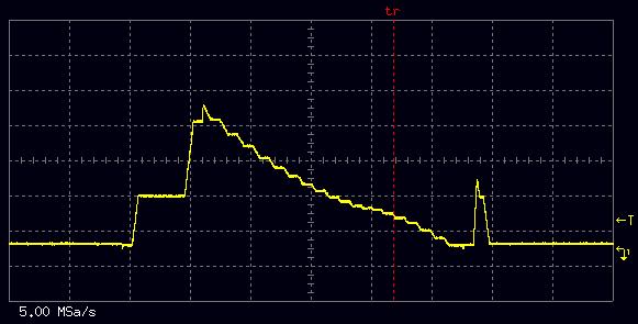
44 View Scope Distorted D/A output as measured by scope Scope triggered to find max distortion with G1 and G2 markers positioned at start and end of first flat distortion.

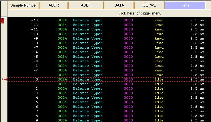
45 Inverse Assembly: Listing Correlated to Waveform at G1 State listing reveals code branching just prior to G1.

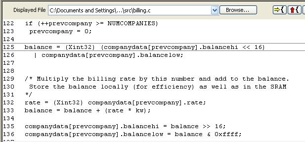
46 Source Correlation: Interrupt Service Routine Source Code Between G1 and G2 D/A execution is interrupted when code goes to interrupt service routine. Line 55 correlated to G1 marker in state listing and waveform.

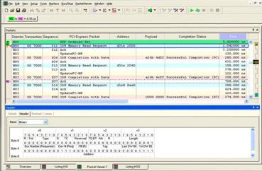
47 Protocol Analysis: Packet Viewer Displays parallel bus data at protocol level Protocol trigger macro allows easy trigger setup, eliminates manual configuration of complex measurements Time correlation with other system buses Coverage includes: Rapid IO PCIE Express USB Serial ATA Proprietary/Custom Protocols

48 Eye Diagrams: Eye Scan What is Eye Scan? Provides signal integrity validation measurements of entire high-speed buses. Uses high resolution comparators to scan across specified time and voltage range. Provides up to 5mV and 10ps resolution. Can be used as a tool of first attack to reveal tough signal integrity problems.


49 FPGA Dynamic Probe FPGA Dynamic Probe SW application supported by 1680/1690/16900 Probe core output Parallel PC Board FPGA Insert ATC2 core with Xilinx Core Inserter ATC2 Control access to new signals via JTAG JTAG
50 Summary
51 Using a Logic Analyzer vs. an Oscilloscope Use a Logic Analyzer to: See many signals at once Look at signals the same way your hardware does (State Mode) Trigger on a pattern of highs and lows on several lines and see the result Use an Oscilloscope: To get precise time interval information To look at the analog characteristics of a signal Verify timing relationships among several or hundreds of lines (Timing Mode)
52 State vs. Timing Timing Analysis When the event happened Edge relationships Hardware debug State Analysis What sequence of operations executed Monitor execution of processor Software and System Integration


53 Common Applications for Logic Analyzers Intel FSB DDR/DDR2/DDR3 Fully Buffered DIMM PCI Express Digital Radio Digital I&Q SATA/SAS InfiniBand RapidIO SPI 4.2 Fibre Channel USB 2.0 IEEE 1394 FPGA Functional Verification Other µp


54 Multiple Views Provide the Right Level of Insight System Performance Eye Scan Listing & IA Oscilloscope Waveform Digital VSA Packet Decode Source Code

55 Introducing Agilent series Logic Analyzer 4 GHz Timing 64K deep Up to 1 GHz timing with deep memory Up to 450 MHz state clock rate Up to 500 Mb/s state data rate Up to 32 M deep memory compatible with 19 years of legacy probing + newest connectorless probing innovations Pattern Generator: 48 channels Up to 16 M vectors deep, Up to 300 Mb/s
56 Q & A
Logic Analysis Basics
 Logic Analysis Basics September 27, 2006 presented by: Alex Dickson Copyright 2003 Agilent Technologies, Inc. Introduction If you have ever asked yourself these questions: What is a logic analyzer? What
Logic Analysis Fundamentals
 Logic Analysis Fundamentals Synchronous and asynchronous capture, combined with the right triggering, is the key to efficient digital system debug Application Note Introduction Today, a wide range of end
Identifying Setup and Hold Violations with a Mixed Signal Oscilloscope APPLICATION NOTE
 Identifying Setup and Hold Violations with a Mixed Signal Oscilloscope Introduction Timing relationships between signals are critical to reliable operation of digital designs. With synchronous designs,
SignalTap Plus System Analyzer
 SignalTap Plus System Analyzer June 2000, ver. 1 Data Sheet Features Simultaneous internal programmable logic device (PLD) and external (board-level) logic analysis 32-channel external logic analyzer 166
Logic Analyzer Triggering Techniques to Capture Elusive Problems
 Logic Analyzer Triggering Techniques to Capture Elusive Problems Efficient Solutions to Elusive Problems For digital designers who need to verify and debug their product designs, logic analyzers provide
Advanced Troubleshooting with Oscilloscopes 9000 Scope Hands-on Labs
 Advanced Troubleshooting with Oscilloscopes 9000 Scope Hands-on Labs Page Lab 1: Scope-based Protocol Analysis 2 Lab 2: Measurements & Analysis 10 Lab 3: InfiniiScan Zone-qualified Triggering 19 Lab 4:
MSO-28 Oscilloscope, Logic Analyzer, Spectrum Analyzer
 Link Instruments Innovative Test & Measurement solutions since 1986 Store Support Oscilloscopes Logic Analyzers Pattern Generators Accessories MSO-28 Oscilloscope, Logic Analyzer, Spectrum Analyzer $ The
Solutions to Embedded System Design Challenges Part II
 Solutions to Embedded System Design Challenges Part II Time-Saving Tips to Improve Productivity In Embedded System Design, Validation and Debug Hi, my name is Mike Juliana. Welcome to today s elearning.
Keysight Technologies U4154A AXIe-Based Logic Analyzer Module. Data Sheet
 Keysight Technologies U4154A AXIe-Based Logic Analyzer Module Data Sheet 02 Keysight U4154B AXIe-Based Logic Analyzer Module - Data Sheet Product Description The Keysight Technologies U4154A AXIe-based
The XYZs of Logic Analyzers
 L o g i c A n a l y z e r s ii The XYZs of Logic Analyzers Contents Introduction 1 Where It All Began 1 The Digital Oscilloscope 1 The Logic Analyzer 3 Logic Analyzer Architecture and Operation 5 Probe
Keysight U4164A Logic Analyzer Module
 Ihr Spezialist für Mess- und Prüfgeräte Keysight U4164A Logic Analyzer Module with Options up to 4 Gb/s State Mode and 10 GHz Timing Mode Data Sheet datatec Ferdinand-Lassalle-Str. 52 72770 Reutlingen
Quick Signal Integrity Troubleshooting with Integrated Logic Analyzers & Oscilloscopes
 Application Overview Quick Signal Integrity Troubleshooting with Integrated Logic Analyzers & Oscilloscopes Meeting Fast Edge Signal Integrity Challenges Fast product development requires fast and efficient
State and Timing Modules for Agilent Technologies Logic Analysis Systems
 State and Timing Modules for Agilent Technologies Logic Analysis Systems Product Overview Your design team faces a difficult challenge: Deliver quality products to the marketplace faster than your competitors.
Experiment # 4 Counters and Logic Analyzer
 EE20L - Introduction to Digital Circuits Experiment # 4. Synopsis: Experiment # 4 Counters and Logic Analyzer In this lab we will build an up-counter and a down-counter using 74LS76A - Flip Flops. The
Low-speed serial buses are used in wide variety of electronics products. Various low-speed buses exist in different
 Low speed serial buses are widely used today in mixed-signal embedded designs for chip-to-chip communication. Their ease of implementation, low cost, and ties with legacy design blocks make them ideal
CAN, LIN and FlexRay Protocol Triggering and Decode for Infiniium 9000A and 9000 H-Series Oscilloscopes
 CAN, LIN and FlexRay Protocol Triggering and Decode for Infiniium 9000A and 9000 H-Series Oscilloscopes Data sheet This application is available in the following license variations. Order N8803B for a
Fundamentals. of Timing Analysis
 Fundamentals of Timing Analysis Table of Contents Introduction....................................................................................................4 Timing Analysis Challenges.....................................................................................4-5
Analyzing 8b/10b Encoded Signals with a Real-time Oscilloscope Real-time triggering up to 6.25 Gb/s on 8b/10b encoded data streams
 Presented by TestEquity - www.testequity.com Analyzing 8b/10b Encoded Signals with a Real-time Oscilloscope Real-time triggering up to 6.25 Gb/s on 8b/10b encoded data streams Application Note Application
EXOSTIV TM. Frédéric Leens, CEO
 EXOSTIV TM Frédéric Leens, CEO A simple case: a video processing platform Headers & controls per frame : 1.024 bits 2.048 pixels 1.024 lines Pixels per frame: 2 21 Pixel encoding : 36 bit Frame rate: 24
Chapter 2. Digital Circuits
 Chapter 2. Digital Circuits Logic gates Flip-flops FF registers IC registers Data bus Encoders/Decoders Multiplexers Troubleshooting digital circuits Most contents of this chapter were covered in 88-217
How to Use a Mixed Signal Oscilloscope to Test Digital Circuits
 How to Use a Mixed Signal Oscilloscope to Test Digital Circuits Application Note The ability to present both analog and digital representations of signals make mixed signal oscilloscopes (MSOs) ideal for
Using SignalTap II in the Quartus II Software
 White Paper Using SignalTap II in the Quartus II Software Introduction The SignalTap II embedded logic analyzer, available exclusively in the Altera Quartus II software version 2.1, helps reduce verification
How to Use a Mixed Signal Oscilloscope to Test Digital Circuits APPLICATION NOTE
 How to Use a Mixed Signal Oscilloscope to Test Digital Circuits APPLICATION NOTE Application Note Figure 1. Mixed logic families (TTL & LVPECL) threshold settings on the same MDO4000 digital probe pod.
Chapter 6. Flip-Flops and Simple Flip-Flop Applications
 Chapter 6 Flip-Flops and Simple Flip-Flop Applications Basic bistable element It is a circuit having two stable conditions (states). It can be used to store binary symbols. J. C. Huang, 2004 Digital Logic
How to Measure Digital Baseband and IF Signals Using Agilent Logic Analyzers with Vector Signal Analysis Software
 How to Measure Digital Baseband and IF Signals Using Agilent Logic Analyzers with 89600 Vector Signal Analysis Software Application Note 1559 Measure, evaluate, and troubleshoot digital baseband and IF
T 2 : WR = 0, AD 7 -AD 0 (μp Internal Reg.) T 3 : WR = 1,, M(AB) AD 7 -AD 0 or BDB
 T 3 : WR = 1,, M(AB) AD 7 -AD 0 or BDB") Lecture-17 Memory WRITE Machine Cycle: It also requires only T 1 to T 3 states. The purpose of memory write machine cycle is to store the contents of any of the 8085A register such as the accumulator into
Lecture-17 Memory WRITE Machine Cycle: It also requires only T 1 to T 3 states. The purpose of memory write machine cycle is to store the contents of any of the 8085A register such as the accumulator into
Tutorial 11 ChipscopePro, ISE 10.1 and Xilinx Simulator on the Digilent Spartan-3E board
 Tutorial 11 ChipscopePro, ISE 10.1 and Xilinx Simulator on the Digilent Spartan-3E board Introduction This lab will be an introduction on how to use ChipScope for the verification of the designs done on
RS-232/UART Triggering and Hardware-Based Decode (N5457A) for Agilent InfiniiVision Oscilloscopes
 for Agilent InfiniiVision Oscilloscopes") Find and debug intermittent errors and signal integrity problems faster RS-232/UART Triggering and Hardware-Based Decode (N5457A) for Agilent InfiniiVision Oscilloscopes Data Sheet Features: RS-232/UART
Find and debug intermittent errors and signal integrity problems faster RS-232/UART Triggering and Hardware-Based Decode (N5457A) for Agilent InfiniiVision Oscilloscopes Data Sheet Features: RS-232/UART
What's the SPO technology?
 What's the SPO technology? SDS2000 Series digital storage oscilloscope, with bandwidth up to 300 MHz, maximum sampling rate 2GSa/s, a deep memory of 28Mpts, high capture rate of 110,000wfs/s, multi-level
BUSES IN COMPUTER ARCHITECTURE
 BUSES IN COMPUTER ARCHITECTURE The processor, main memory, and I/O devices can be interconnected by means of a common bus whose primary function is to provide a communication path for the transfer of data.
Agilent Technologies Pulse Pattern and Data Generators Digital Stimulus Solutions
 Agilent Technologies Pattern and Data Generators Digital Stimulus Solutions Leading pulse, pattern, data and clock generation for all test needs in digital design and manufacturing Pattern Generators Agilent
Manual Supplement. This supplement contains information necessary to ensure the accuracy of the above manual.
 Manual Title: 9500B Users Supplement Issue: 2 Part Number: 1625019 Issue Date: 9/06 Print Date: October 2005 Page Count: 6 Version 11 This supplement contains information necessary to ensure the accuracy
Selecting the Right Oscilloscope for Protocol Analysis Applications
 Selecting the Right Oscilloscope for Protocol Analysis Applications Application Note Serial buses are pervasive in today s electronic designs to provide critical communication between ICs, subsystems,
Using the XC9500/XL/XV JTAG Boundary Scan Interface
 Application Note: XC95/XL/XV Family XAPP69 (v3.) December, 22 R Using the XC95/XL/XV JTAG Boundary Scan Interface Summary This application note explains the XC95 /XL/XV Boundary Scan interface and demonstrates
Choosing an Oscilloscope
 Choosing an Oscilloscope By Alan Lowne CEO Saelig Company (www.saelig.com) Post comments on this article at www.nutsvolts.com/ magazine/article/october2016_choosing-oscilloscopes. All sorts of questions
Advanced Test Equipment Rentals ATEC (2832) Agilent Technologies 16700B and 16702B Logic Analysis Systems
 Agilent Technologies 16700B and 16702B Logic Analysis Systems") Established 1981 Advanced Test Equipment Rentals www.atecorp.com 800-404-ATEC (2832) Agilent Technologies 16700B and 16702B Logic Analysis Systems 1 connect 2 acquire 3 view & analyze Introduction From
Established 1981 Advanced Test Equipment Rentals www.atecorp.com 800-404-ATEC (2832) Agilent Technologies 16700B and 16702B Logic Analysis Systems 1 connect 2 acquire 3 view & analyze Introduction From
HAMEG. Oscilloscopes. Innovation right from the start. Oscilloscopes
 HAMEG Oscilloscopes Innovation right from the start Without doubt, the oscilloscope is the most important measuring instrument for the characterization of signals in the time domain. HAMEG Instruments
SignalTap Analysis in the Quartus II Software Version 2.0
 SignalTap Analysis in the Quartus II Software Version 2.0 September 2002, ver. 2.1 Application Note 175 Introduction As design complexity for programmable logic devices (PLDs) increases, traditional methods
Agilent MSO and CEBus PL Communications Testing Application Note 1352
 546D Agilent MSO and CEBus PL Communications Testing Application Note 135 Introduction The Application Zooming In on the Signals Conclusion Agilent Sales Office Listing Introduction The P300 encapsulates
Mixed Analog and Digital Signal Debug and Analysis Using a Mixed-Signal Oscilloscope Wireless LAN Example Application
 Mixed Analog and Digital Signal Debug and Analysis Using a Mixed-Signal Oscilloscope Wireless LAN Example Application Application Note 1418 Table of Contents Introduction......................1 Debugging
More on Flip-Flops Digital Design and Computer Architecture: ARM Edition 2015 Chapter 3 <98> 98
 More on Flip-Flops Digital Design and Computer Architecture: ARM Edition 2015 Chapter 3 98 Review: Bit Storage SR latch S (set) Q R (reset) Level-sensitive SR latch S S1 C R R1 Q D C S R D latch Q
Flip-Flops and Related Devices. Wen-Hung Liao, Ph.D. 4/11/2001
 Flip-Flops and Related Devices Wen-Hung Liao, Ph.D. 4/11/2001 Objectives Recognize the various IEEE/ANSI flip-flop symbols. Use state transition diagrams to describe counter operation. Use flip-flops in
Meeting Embedded Design Challenges with Mixed Signal Oscilloscopes
 Meeting Embedded Design Challenges with Mixed Signal Oscilloscopes Introduction Embedded design and especially design work utilizing low speed serial signaling is one of the fastest growing areas of digital
LAX_x Logic Analyzer
 Legacy documentation LAX_x Logic Analyzer Summary This core reference describes how to place and use a Logic Analyzer instrument in an FPGA design. Core Reference CR0103 (v2.0) March 17, 2008 The LAX_x
Combating Closed Eyes Design & Measurement of Pre-Emphasis and Equalization for Lossy Channels
 Combating Closed Eyes Design & Measurement of Pre-Emphasis and Equalization for Lossy Channels Why Test the Receiver? Serial Data communications standards have always specified both the transmitter and
Combating Closed Eyes Design & Measurement of Pre-Emphasis and Equalization for Lossy Channels
 Combating Closed Eyes Design & Measurement of Pre-Emphasis and Equalization for Lossy Channels Why Test the Receiver? Serial Data communications standards have always specified both the transmitter and
S op o e p C on o t n rol o s L arni n n i g n g O bj b e j ctiv i e v s
 ET 150 Scope Controls Learning Objectives In this lesson you will: learn the location and function of oscilloscope controls. see block diagrams of analog and digital oscilloscopes. see how different input
Evaluating Oscilloscopes to Debug Mixed-Signal Designs
 Introduction Evaluating Oscilloscopes to Debug Mixed-Signal Designs Our thanks to Agilent for allowing us to reprint the following article. Today s embedded designs based on microcontrollers (MCUs) and
MS-32. Oscilloscope Mixed Signal Option. Add 32 Digital Channels to a 4 Channel Oscilloscope
 MS-32 Oscilloscope Mixed Signal Option Add 32 Digital Channels to a 4 Channel Oscilloscope 4 Analog + 32 Digital Channel Capability LeCroy introduces the first oscilloscope solution to combine 4 analog
Overview. Know Your Oscilloscope. Front Panel. Rear Panel. Sharing Agilent s Resources with Engineering Educators
 Know Your Oscilloscope Overview Front Panel Sharing Agilent s Resources with Engineering Educators www.educatorscorner.com Horizontal (time) controls Run control Special purpose menus/controls Trigger
Application Note #63 Field Analyzers in EMC Radiated Immunity Testing
 Application Note #63 Field Analyzers in EMC Radiated Immunity Testing By Jason Galluppi, Supervisor Systems Control Software In radiated immunity testing, it is common practice to utilize a radio frequency
Introduction. NAND Gate Latch. Digital Logic Design 1 FLIP-FLOP. Digital Logic Design 1
 2007 Introduction BK TP.HCM FLIP-FLOP So far we have seen Combinational Logic The output(s) depends only on the current values of the input variables Here we will look at Sequential Logic circuits The
Logic Analyzer Auto Run / Stop Channels / trigger / Measuring Tools Axis control panel Status Display
 Logic Analyzer The graphical user interface of the Logic Analyzer fits well into the overall design of the Red Pitaya applications providing the same operating concept. The Logic Analyzer user interface
Timesaving Tips for Digital Debugging with a Logic Analyzer
 Timesaving Tips for Digital Debugging with a Logic Analyzer Application Note New Designs, New Headaches New digital devices have become progressively more powerful by incorporating faster microprocessors
How to Measure Digital Baseband and IF Signals Using Agilent Logic Analyzers with Vector Signal Analysis Software
 How to Measure Digital Baseband and IF Signals Using Agilent Logic Analyzers with 89600 Vector Signal Analysis Software Application Note 1559 Measure, evaluate, and troubleshoot digital baseband and IF
HDL & High Level Synthesize (EEET 2035) Laboratory II Sequential Circuits with VHDL: DFF, Counter, TFF and Timer
 Laboratory II Sequential Circuits with VHDL: DFF, Counter, TFF and Timer") 1 P a g e HDL & High Level Synthesize (EEET 2035) Laboratory II Sequential Circuits with VHDL: DFF, Counter, TFF and Timer Objectives: Develop the behavioural style VHDL code for D-Flip Flop using gated,
1 P a g e HDL & High Level Synthesize (EEET 2035) Laboratory II Sequential Circuits with VHDL: DFF, Counter, TFF and Timer Objectives: Develop the behavioural style VHDL code for D-Flip Flop using gated,
System IC Design: Timing Issues and DFT. Hung-Chih Chiang
 System IC esign: Timing Issues and FT Hung-Chih Chiang Outline SoC Timing Issues Timing terminologies Synchronous vs. asynchronous design Interfaces and timing closure Clocking issues Reset esign for Testability
VHDL Design and Implementation of FPGA Based Logic Analyzer: Work in Progress
 VHDL Design and Implementation of FPGA Based Logic Analyzer: Work in Progress Nor Zaidi Haron Ayer Keroh +606-5552086 zaidi@utem.edu.my Masrullizam Mat Ibrahim Ayer Keroh +606-5552081 masrullizam@utem.edu.my
The Measurement Tools and What They Do
 2 The Measurement Tools The Measurement Tools and What They Do JITTERWIZARD The JitterWizard is a unique capability of the JitterPro package that performs the requisite scope setup chores while simplifying
Agilent I 2 C Debugging
 546D Agilent I C Debugging Application Note1351 With embedded systems shrinking, I C (Inter-integrated Circuit) protocol is being utilized as the communication channel of choice because it only needs two
Keysight Technologies CAN/LIN Measurements (Option AMS) for InfiniiVision Series Oscilloscopes
 for InfiniiVision Series Oscilloscopes") Ihr Spezialist für Mess- und Prüfgeräte Keysight Technologies CAN/LIN Measurements (Option AMS) for InfiniiVision Series Oscilloscopes Data Sheet Introduction Debug the signal integrity of your CAN and
Ihr Spezialist für Mess- und Prüfgeräte Keysight Technologies CAN/LIN Measurements (Option AMS) for InfiniiVision Series Oscilloscopes Data Sheet Introduction Debug the signal integrity of your CAN and
MS-32 OSCILLOSCOPE MIXED SIGNAL OPTION. Add 32 Digital Channels to a 4 Channel Oscilloscope
 MS-32 OSCILLOSCOPE MIXED SIGNAL OPTION Add 32 Digital Channels to a 4 Channel Oscilloscope 4 Analog + 32 Digital Channel Capability LeCroy introduces the first oscilloscope solution to combine 4 analog
DEDICATED TO EMBEDDED SOLUTIONS
 DEDICATED TO EMBEDDED SOLUTIONS DESIGN SAFE FPGA INTERNAL CLOCK DOMAIN CROSSINGS ESPEN TALLAKSEN DATA RESPONS SCOPE Clock domain crossings (CDC) is probably the worst source for serious FPGA-bugs that
CAN/LIN Measurements (Option AMS) for Agilent s InfiniiVision Series Oscilloscopes
 for Agilent s InfiniiVision Series Oscilloscopes") CAN/LIN Measurements (Option AMS) for Agilent s InfiniiVision Series Oscilloscopes Data Sheet Debug the signal integrity of your CAN and LIN designs faster Introduction The Agilent Technologies InfiniiVision
CAN/LIN Measurements (Option AMS) for Agilent s InfiniiVision Series Oscilloscopes Data Sheet Debug the signal integrity of your CAN and LIN designs faster Introduction The Agilent Technologies InfiniiVision
Tektronix Logic Analyzers
 공식채널파트너 Tektronix Logic Analyzers TLA6400 Series Datasheet Comprehensive Set of Signal Integrity Tools that Allow You to Quickly Isolate, Identify, and Debug Complex Signal Integrity Issues Glitch Trigger
Chapter 5 Flip-Flops and Related Devices
 Chapter 5 Flip-Flops and Related Devices Chapter 5 Objectives Selected areas covered in this chapter: Constructing/analyzing operation of latch flip-flops made from NAND or NOR gates. Differences of synchronous/asynchronous
Troubleshooting Your Design with the TDS3000C Series Oscilloscopes
 Troubleshooting Your Design with the 2 Table of Contents Getting Started........................................................... 4 Debug Digital Timing Problems...............................................
Keysight Technologies Mixed Analog and Digital Signal Debug and Analysis Using a Mixed-Signal Oscilloscope
 Keysight Technologies Mixed Analog and Digital Signal Debug and Analysis Using a Mixed-Signal Oscilloscope Wireless LAN Example Application Application Note Introduction Many of today s designs include
1. Abstract. Mixed Signal Oscilloscope Ideal For Debugging Embedded Systems DLM2000 Series
 Yokogawa Electric Corporation High Frequency Measurement Development Dept. C&M Business HQ. Motoaki Sugimoto 1. Abstract From digital home electronics to automobiles, a boom has recently occurred in various
How to overcome/avoid High Frequency Effects on Debug Interfaces Trace Port Design Guidelines
 How to overcome/avoid High Frequency Effects on Debug Interfaces Trace Port Design Guidelines An On-Chip Debugger/Analyzer (OCD) like isystem s ic5000 (Figure 1) acts as a link to the target hardware by
Portable Performance for Debug and Validation
 WaveJet 300A Oscilloscopes 100 MHz 500 MHz Portable Performance for Debug and Validation A UNIQUE TOOLSET FOR PORTABLE OSCILLOSCOPES Key Features 100 MHz, 200 MHz, 350 MHz and 500 MHz bandwidths Sample
Lab #5: Design Example: Keypad Scanner and Encoder - Part 1 (120 pts)
") Nate Pihlstrom, npihlstr@uccs.edu Lab #5: Design Example: Keypad Scanner and Encoder - Part 1 (120 pts) Objective The objective of lab assignments 5 through 9 are to systematically design and implement
Nate Pihlstrom, npihlstr@uccs.edu Lab #5: Design Example: Keypad Scanner and Encoder - Part 1 (120 pts) Objective The objective of lab assignments 5 through 9 are to systematically design and implement
Lecture 23 Design for Testability (DFT): Full-Scan
: Full-Scan") Lecture 23 Design for Testability (DFT): Full-Scan (Lecture 19alt in the Alternative Sequence) Definition Ad-hoc methods Scan design Design rules Scan register Scan flip-flops Scan test sequences Overheads
Lecture 23 Design for Testability (DFT): Full-Scan (Lecture 19alt in the Alternative Sequence) Definition Ad-hoc methods Scan design Design rules Scan register Scan flip-flops Scan test sequences Overheads
EECS150 - Digital Design Lecture 10 - Interfacing. Recap and Topics
 EECS150 - Digital Design Lecture 10 - Interfacing Oct. 1, 2013 Prof. Ronald Fearing Electrical Engineering and Computer Sciences University of California, Berkeley (slides courtesy of Prof. John Wawrzynek)
Debugging Memory Interfaces using Visual Trigger on Tektronix Oscilloscopes
 Debugging Memory Interfaces using Visual Trigger on Tektronix Oscilloscopes Application Note What you will learn: This document focuses on how Visual Triggering, Pinpoint Triggering, and Advanced Search
Serial Decode I2C TEN MINUTE TUTORIAL. December 21, 2011
 Serial Decode I2C TEN MINUTE TUTORIAL December 21, 2011 Summary LeCroy oscilloscopes have the ability to trigger on and decode multiple serial data protocols. The decode in binary, hex, or ASCII format,
Oscilloscopes, logic analyzers ScopeLogicDAQ
 Oscilloscopes, logic analyzers ScopeLogicDAQ ScopeLogicDAQ 2.0 is a comprehensive measurement system used for data acquisition. The device includes a twochannel digital oscilloscope and a logic analyser
Agilent 6000 Series Oscilloscope Demo Guide
 Agilent 6000 Series Oscilloscope Demo Guide Agilent 6000 Series Oscilloscope Demo Guide A series of portable oscilloscopes for today s and tomorrow s projects. In the next few minutes you will experience
Agilent Technologies N5454A Segmented Memory Acquisition for Agilent InfiniiVision Series Oscilloscopes
 Agilent Technologies N5454A Segmented Memory Acquisition for Agilent InfiniiVision Series Oscilloscopes Data Sheet Capture more signal detail with less memory using segmented memory acquisition Features:
The outputs are formed by a combinational logic function of the inputs to the circuit or the values stored in the flip-flops (or both).
.") 1 The outputs are formed by a combinational logic function of the inputs to the circuit or the values stored in the flip-flops (or both). The value that is stored in a flip-flop when the clock pulse occurs
1 The outputs are formed by a combinational logic function of the inputs to the circuit or the values stored in the flip-flops (or both). The value that is stored in a flip-flop when the clock pulse occurs
82C55A CHMOS PROGRAMMABLE PERIPHERAL INTERFACE
 Y Y Y Y Y 82C55A CHMOS PROGRAMMABLE PERIPHERAL INTERFACE Compatible with all Intel and Most Other Microprocessors High Speed Zero Wait State Operation with 8 MHz 8086 88 and 80186 188 24 Programmable I
COE758 Xilinx ISE 9.2 Tutorial 2. Integrating ChipScope Pro into a project
 COE758 Xilinx ISE 9.2 Tutorial 2 ChipScope Overview Integrating ChipScope Pro into a project Conventional Signal Sampling Xilinx Spartan 3E FPGA JTAG 2 ChipScope Pro Signal Sampling Xilinx Spartan 3E FPGA
How advances in digitizer technologies improve measurement accuracy
 How advances in digitizer technologies improve measurement accuracy Impacts of oscilloscope signal integrity Oscilloscopes Page 2 By choosing an oscilloscope with superior signal integrity you get the
Logic Devices for Interfacing, The 8085 MPU Lecture 4
 Logic Devices for Interfacing, The 8085 MPU Lecture 4 1 Logic Devices for Interfacing Tri-State devices Buffer Bidirectional Buffer Decoder Encoder D Flip Flop :Latch and Clocked 2 Tri-state Logic Outputs
Laboratory 1 - Introduction to Digital Electronics and Lab Equipment (Logic Analyzers, Digital Oscilloscope, and FPGA-based Labkit)
") Massachusetts Institute of Technology Department of Electrical Engineering and Computer Science 6. - Introductory Digital Systems Laboratory (Spring 006) Laboratory - Introduction to Digital Electronics
Massachusetts Institute of Technology Department of Electrical Engineering and Computer Science 6. - Introductory Digital Systems Laboratory (Spring 006) Laboratory - Introduction to Digital Electronics
ECT 224: Digital Computer Fundamentals Digital Circuit Simulation & Timing Analysis
 ECT 224: Digital Computer Fundamentals Digital Circuit Simulation & Timing Analysis 1) Start the Xilinx ISE application, open Start All Programs Xilinx ISE 9.1i Project Navigator or use the shortcut on
Quick Reference Manual
 Quick Reference Manual V1.0 1 Contents 1.0 PRODUCT INTRODUCTION...3 2.0 SYSTEM REQUIREMENTS...5 3.0 INSTALLING PDF-D FLEXRAY PROTOCOL ANALYSIS SOFTWARE...5 4.0 CONNECTING TO AN OSCILLOSCOPE...6 5.0 CONFIGURE
Realizing Waveform Characteristics up to a Digitizer s Full Bandwidth Increasing the effective sampling rate when measuring repetitive signals
 Realizing Waveform Characteristics up to a Digitizer s Full Bandwidth Increasing the effective sampling rate when measuring repetitive signals By Jean Dassonville Agilent Technologies Introduction The
AI-1204Z-PCI. Features. 10MSPS, 12-bit Analog Input Board for PCI AI-1204Z-PCI 1. Ver.1.04
 10MSPS, 12-bit Analog Board for PCI AI-1204Z-PCI * Specifications, color and design of the products are subject to change without notice. This product is a PCI bus-compliant interface board that expands
A dedicated data acquisition system for ion velocity measurements of laser produced plasmas
 A dedicated data acquisition system for ion velocity measurements of laser produced plasmas N Sreedhar, S Nigam, Y B S R Prasad, V K Senecha & C P Navathe Laser Plasma Division, Centre for Advanced Technology,
National Instruments Synchronization and Memory Core a Modern Architecture for Mixed Signal Test
 National Instruments Synchronization and Memory Core a Modern Architecture for Mixed Signal Test Introduction Today s latest electronic designs are characterized by their converging functionality and
PicoScope 6407 Digitizer
 YE AR PicoScope 6407 Digitizer HIGH PERFORMANCE USB DIGITIZER Programmable and Powerful 1 GHz bandwidth 1 GS buffer size 5 GS/s real-time sampling Advanced digital triggers Built-in function generator
Digital Audio Design Validation and Debugging Using PGY-I2C
 Digital Audio Design Validation and Debugging Using PGY-I2C Debug the toughest I 2 S challenges, from Protocol Layer to PHY Layer to Audio Content Introduction Today s digital systems from the Digital
Laboratory Exercise 4
 Laboratory Exercise 4 Polling and Interrupts The purpose of this exercise is to learn how to send and receive data to/from I/O devices. There are two methods used to indicate whether or not data can be
Remote Diagnostics and Upgrades
 Remote Diagnostics and Upgrades Tim Pender -Eastman Kodak Company 10/03/03 About this Presentation Motivation for Remote Diagnostics Reduce Field Maintenance costs Product needed to support 100 JTAG chains
EMT 125 Digital Electronic Principles I CHAPTER 6 : FLIP-FLOP
 EMT 125 Digital Electronic Principles I CHAPTER 6 : FLIP-FLOP 1 Chapter Overview Latches Gated Latches Edge-triggered flip-flops Master-slave flip-flops Flip-flop operating characteristics Flip-flop applications
Scan. This is a sample of the first 15 pages of the Scan chapter.
 Scan This is a sample of the first 15 pages of the Scan chapter. Note: The book is NOT Pinted in color. Objectives: This section provides: An overview of Scan An introduction to Test Sequences and Test
IT T35 Digital system desigm y - ii /s - iii
 UNIT - III Sequential Logic I Sequential circuits: latches flip flops analysis of clocked sequential circuits state reduction and assignments Registers and Counters: Registers shift registers ripple counters
DIGITAL ELECTRONICS MCQs
 DIGITAL ELECTRONICS MCQs 1. A 8-bit serial in / parallel out shift register contains the value 8, clock signal(s) will be required to shift the value completely out of the register. A. 1 B. 2 C. 4 D. 8
FSM Cookbook. 1. Introduction. 2. What Functional Information Must be Modeled
 FSM Cookbook 1. Introduction Tau models describe the timing and functional information of component interfaces. Timing information specifies the delay in placing values on output signals and the timing