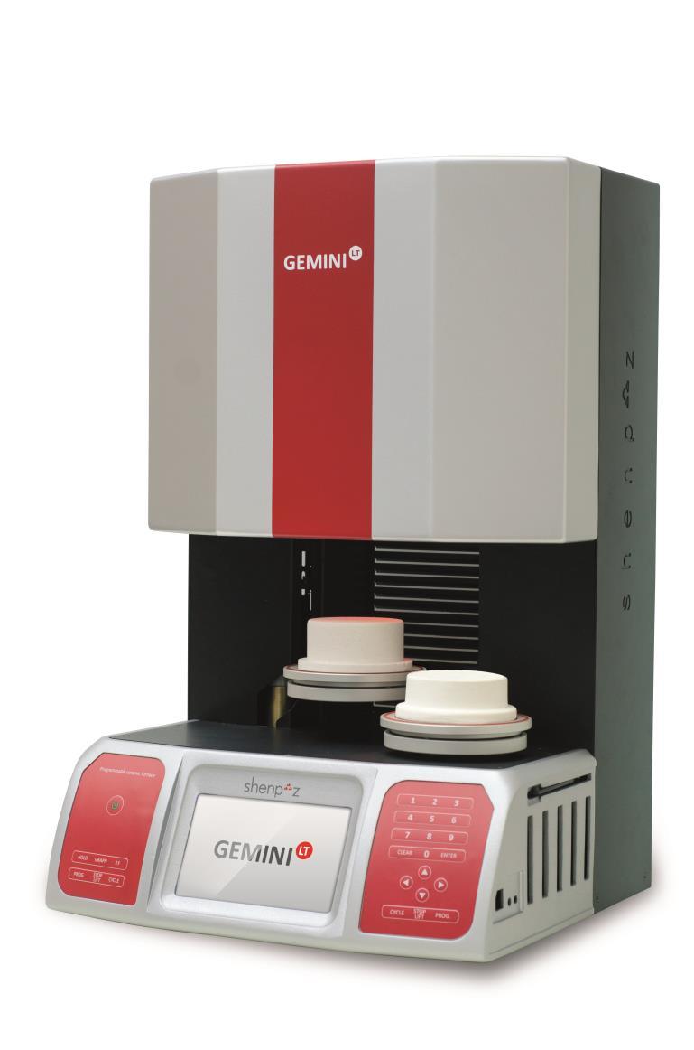
INSTRUCTION MANUAL Gemini LT porcelain firing furnace
|
|
|
- Thomasine Clarke
- 5 years ago
- Views:
Transcription
1
2 INSTRUCTION MANUAL Gemini LT porcelain firing furnace 2 P a g e
3 Warning ATTENTION! You have available one of the most precise dental ceramic furnaces equipped with a heating muffle made of quartz glass or ATC from the original manufacturer of this technology with an experience of more than 25 years. IN ORDER TO PRESERVE THIS PRECISION AT ALL TIMES, PLEASE BE SURE TO ATTENTIVELY READ THE FOLLOWING INSTRUCTIONS PRIOR TO USING THE FURNACE! Prior to carrying out maintenance work on the furnace or in case of mechanical failure, firstly be sure to completely shut down the device. To do so, switch the main switch (POWER) on the back of the furnace to OFF and pull the power-supply plug. Only qualified technicians and experts recommended by the furnace supplier should open the furnace. All pumps connected to the furnace and those which may have been supplied by the manufacturer or by other suppliers must be marked with the CE symbol. In case of doubt, consult your furnace supplier. Be sure to only use ceramics and alloys that are specifically provided for use in dental firing or pressing furnaces. Certain parts of the furnace may run very hot during operation. Be sure to use the complimentary supplied tweezers. Do not attempt to open the furnaces without authorization since this will void the guarantee. For any necessary repair and maintenance work, consult your Shenpaz device servicing center. In case of a necessary replacement of fuses, proceed as follows: 1) Pull the power-supply plug. 2) Replace the fuse. 3) Be sure the correct safety fuse parameter is indicated on the spare fuse. 3 P a g e
4 In case of an external power failure and when the furnace is in operation, proceed as follows: 1) Pull the power-supply plug. 2) Lower the support. To do so, insert the supplied crank into the hexagonal screw on the back of the furnace. ATTENTION! When operating the furnace a Ceramic table or pressure table must always be on the lift tray! ATTENTION! Take out the furnace with both hands. To do so, hold the bottom of the furnace with one hand and the top side with the other hand. ATTENTION! Do not pull out the furnace by its support in order to avoid damages. 4 P a g e
5 Contents Installation... 5 Switches and Keys... 6 Functions, Displays and Programming Menu Functions Diagnosis/Options Menu Technical Data Putting out of Commission and Disposal Distribution and Technical Service Appendix: Pre-Installed Programs / Overview P a g e
6 Installation Unpacking: Check the packaging of the furnace for any visible damage. Check whether all components are present by means of the listing below: 2 Ceramic Table Power cord Pump hose 8A fuse 230v 15A fuse for 100/115v(for the heating) 5A fuse 230v 6.3A fuse for 100/115v (for the pump) Instruction manual Tweezers Emergency 6-mm wrench Additional Components of Gemini LT Press : Pressure Table Cylinder press system, including 2 ShenPaz bases, 2 dies plunger and 2 e-base (compatible to e.max) Note: The packaging was especially designed for proper handling of the furnace and transport safety, we strongly recommend keeping the original packaging for future transportation purpose. Setting Up: Place the furnace on a leveled surface and keep a distance of at least 10 cm from the wall. Keep combustible objects away from the furnace. Do not expose the furnace to direct sunlight in order to avoid possible damages to the LCD display. Protect the furnace from strong air circulation (such as ventilators), since this may result in fluctuations of the temperature display when opening the programs chamber. Power Supply: Connect the furnace to a grounded power socket. Be sure the parameters are in conformity with the electrical specifications of the Gemini LT /Gemini LT Press model. Your furnace is equipped with the latest software recovery system. In case of electrical shut down, your cycle will fully be recovered within a temperature decrease not exceeding 150ºC/302ºF degrees. For a temperature decrease more than this value, the cycle will be aborted to avoid unnecessary firing. Vacuum Pump: 6 P a g e

7 Connect the power-supply plug and vacuum tube to the furnace. Compressed Air: available only in press Connect the furnace to a compressed-air system by means of a compressed-air tube. The maximum in-feed pressure should not exceed 8-10 bar. In order to avoid damages on the furnace, the compressed air must be absolutely dry. Switches and Keys Overview of furnace panel Master Switch: The master switch is at the back of the furnace. Turn switch ON. An audio signal will be heard. 7 P a g e


8 MENU Press Menu to switch on the furnace. The program overview display window will appear and furnace is in Standby mode. Pressing twice on the same button will bring you to the menu setup. IMPORTANT NOTE: The furnace must never be heated without its ceramic table or pressing table in place! Numeric Keys These keys are used to enter parameters, program numbers to be selected, program names and to directly select single menu sub-entries. Arrow Keys The Arrow keys are used for different purposes depending in which screen appears on the display. Control of lift in diagnostic menu, Menu accessed by pressing 8 P a g e Choose left or right working table with lateral arrow. Movement of the lifts (long
9 PF + numeric key 2 press on up or down arrow) In the program overview display window: Selection of parameters to be entered or to be modified (short press on up down arrows) On the display, Program List : Selection of desired program In different screens: Selection of sub-entries In main screen Navigate to Setup (left) or Options (right) Press Left or Right arrow key to go back to the main menu from setup or options. Cycle Key (left or right) There are 2 cycle keys, one for each working table. Press this key to start the selected program on the relevant side. STOP Key Press this key twice to abort the currently running program (safety query). The firing chamber opens up. HoldKey Press this key to intervene in a currently running program. This function ("Hold key) is used to modify a currently running program. The forthcoming parameters in the current program will be changed temporally. The original saved program remains unchanged. Proceed as follows: 1. Press the HOLD key (the program is interrupted) 9 P a g e
10 2. Press the arrow and numeric keys to modify the program parameters. 3. Press the ENTER key to confirm. 4. Press this key again to resume the program. While the cycle is called but not running: Press this key in the operation mode to call up the Name Editor. Program Key There are two PROG keys on the front panel, on for each working table. This key is used to select a program number for the respective working table; after pressing the PROG. key; press the numeric key(s) to select the program number; confirm by pressing the ENTER key. The list and the chosen program will appear automatically after pressing "prog+xxx". Switching to Graphic Diagram and return to parameter screen Press this key to switch the display into a graphic diagram. Pressing a second time will return the display to the parameters screen. PF Pre Functions Press this key in standby mode to activate the diagnosis mode. Night Mode In order to considerably extend the life of the heating, keep a constant temperature of 100 C. There are two methods to start the night mode: 1. Start the program "0 to activate the "normal Night Mode. 10 P a g e
11 The "automatic Night Mode" will start only when a program is running, if the Cycle key is pressed when said program is running. Press the Cycle key for a second time will deactivate the "automatic Night Mode. 11 P a g e
12 Functions, Displays and Programming Program Overview Display Window This display is divided up in different sections and two different colors. The dark blue background represents all parameters and status of the left swivel work table. The white background represents all parameters and status of the right swivel working table. For example, refer to the below screen shots: The status section is on the left side of the display and shows the respectively current status of the program for the left working table ( upper part) and the program for right working (lower part) The top left side of the display indicates the All parameters of the program are displayed program number for the left swivel working on the right display page. The right side of table is 20, the name of the program and this screen is used to enter and edit time. programs. In the middle, the real status of the running In dark blue while programming Left program (dark blue or white according to Program. which table is working). In Inverse mode white while programming The lower left side of the display indicates the Right Program. program number for the right swivel working table is 21, the name of the program and time. The Vacuum value for each parameter will appear on the middle left section VAC. The vacuum parameters are displayed in the center of the display: ON-OFF-DELAY- LEVEL Graphic Representation This picture shows a graphic representation of the currently running program and its parameters. 12 P a g e
13 When selecting a pressing program (Gemini LT Press), the pressure level will be Modes Program number 1 is preset, Preheat mode used for extracting the moisture from the muffle and drying of the muffle. On Gemini LT, the program digits are available for the "programming. Unlike the above, the program digits on Gemini LT Press are configured in Delete Choice of Programs and Starting the Program Press the PROG key on the chosen side to access the pre-stored list. By using the arrow keys, you can navigate through the list or press directly the program numbers by means of the numeric keys. Press ENTER to confirm your selection. Press the CYCLE key on the chosen side to start the program. The word CYC will appear in inverse color while work is in cycle. Once the program is completed, the firing chamber opens up and an audio signal is heard. The current program will end a few seconds later. If another program is programmed for the other working table, it will begin automatically after reaching to the Low temp of the new program. 13 P a g e

14 Pre-heating Program Important note: During transportation, storage and non-use, the isolation material of the muffle may absorb humidity. In order to avoid damages to the vacuum and heating system and in order to always obtain repeatable quality firing results, it is recommended that the user run the pre-heating program (program digit 1) at the beginning of such periods. This is always recommended if the furnace has been completely cooled down after operation Menu Functions To access the MENU, use the right arrow key. There are 7 sub-entries: Use numeric keys to make a selection. 0. Turn off furnace 1. Edit current program: This function allows you to edit also the program parameter, one by one in addition to the direct access to the parameters from the main screen with the arrow down and up. 2. Options: Allow you to configure your furnace default parameters,: C /F /mmhg/mbar/hpa, calibration adjustment, pump cooling, Language, time to graph, 11 parameters or 13 parameters, vacuum level preset. * if the value of the vacuum are preset they will not appear on the parameters screen. By changing options in this screen, display configurations will automatically appear depending on option selected. NOTE: Functionally the entered program will perform as intended; the only difference is visual on the screen display. 14 P a g e


15 The following 4 screen samples are the only display configurations possible in the furnace. 11 Parameters without Vacuum preset 12 Parameters with vacuum preset 13 Parameters without vacuum preset: 10 Parameters with Vacuum preset 15 P a g e

 LIFT UP TIME Selection of lift parameters when closing. Press the arrow keys, numeric keys and ENTER to edit.")
16 3. Diagnostic menu : See next section 4. Setup menu: 5. Final temp & Heat rate Tempering: opening of the table for every cycle Preset of closing and opening of every program can be set in this section also, follow the info on the screen: Navigate with the arrows, write the new value within the limit and save. Details Setup screen for lift: 1. Lift Positions Closing (program-specific) LIFT UP TIME Selection of lift parameters when closing. Press the arrow keys, numeric keys and ENTER to edit. The respective lift path is edited in the left column, whereas the halt periods are edited in % in the right column (relative to the complete lift closed time of 16 P a g e
 Selection of lift parameters when opening.")


17 the respective program). 2. Lift Positions Opening (program-specific) Selection of lift parameters when opening. Press the arrow keys, numeric keys and ENTER to edit. The respective lift path is edited in the left column, whereas the halt periods are edited in % in the right column (relative to the complete lift open time of the respective program). 3-Tempering: opening of the table for every cycle Preset of closing and opening of every program can be set in this section also, follow the info on the screen: Navigate with the arrows, write the new value within the limit and save 6. Editing the Program Name: 17 P a g e
18 In order to edit the program name, press number "5" + ENT in the menu Entering a new program name by means of the Numeric keys. To switch the numbers on the screen to corresponding letter, use the up/down arrows. The Numeric keys will correspond to the letters that appear on the display screen. Editing an existing program name, using the right/left arrows selects the place to edit. The cursor shifts position by means of the arrow keys. The left CYCLE key is used to shift between the upper and lower case. Editing the Program Contents 1. Press the arrow keys to select the characters. 2. Press the numeric keys to enter the characters. 3. To edit further characters, follow the steps 1 and 2 above. 4. Press ENTER to confirm. 18 P a g e

19 Diagnosis/Options Menu Press the 3 key + ENT to call up the diagnosis menu when the standby mode of the furnace has been activated (the furnace name is shown in the display). Press the respective numeric key to call up the desired function. Overview display window with the diagnosis tools available for selection by choosing the number and press "ent" button you choose the relevant screen 0/Oven Data This is to show the basic data of the furnace. These data show important notes in case of a possible failure or error. Moreover, the software version as well as the calibration values will appear. 1/ Restoring all Programs The programs and setting data including the lift parameters set by the manufacturer will be restored again, if they have been changed during operation. To do so, press the numeric key 1+ENT in the diagnosis menu. The preset default programs will be restored after a few minutes. Warning! This operation will erase the program into the furnace 2/ Log: only for technician purpose. 3/ Multi cycle: only for technician purpose 4/ Load USB: only for technician purpose 19 P a g e


20 5/ Keyboard Test This diagnosis function is used to check the keyboard and to determine the proper functioning of all keys. The keyboard is shown on the display. To carry out the test, press each key once and check whether the respective symbol appears on the display. 6/ Vacuum Calibration This is a servicing function which should exclusively be carried out by a device expert only. Warning! This operation will erase the program into the furnace 7/ Temperature Calibration This is a servicing function which should exclusively be carried out by a device expert only. Warning! This operation will erase the program into the furnace 8/ Delete Temp calibration: only for technician purpose Warning! This operation will erase the program into the furnace 9/ Hardware Test This is to check the individual components. Press the ON key to test the press die. The amount of pressure applied (in bar) appears on the line below. Press start to start/ stop/release vacuum For the rest follow the instruction on the screen 20 P a g e

21 10/ Hours meters In this screen you can follow the utilization of your muffle. It is recommended to replace your muffle every 3000 Hour working cycle above 600 degrees. 11/ Last auto test: only for technician purpose 12/ Auto test: only for technician purpose 21 P a g e
22 Technical Data General: Dimensions 450 mm x 450mm x 680mm (H); Muffle chamber Ø95 mm x 60 mm; Ø 3.7"x 2.6" Combustion Table Ø 90 mm; Ø 3.5" Net Weight 35Kg / 89 lbs Heating Speed 230 V from 10 to 100 C/ ºF 115V from 10 to 100 C/50-212ºF Pump capacity 230v 5 A 115/100v 6.3A Mains voltage 230 V 1750 W 50/60 Hz 115V 1100 W 50/60 Hz Vacuum Level Up to 980 mbar Up to 740 mmhg Time In Min and Sec mm:ss Temperature Range 100 to 1180 C; 112º to 2156ºF Transportation and storing conditions Temperature 0 C to 40 C; 32º to 104ºF Relative air humidity Less than 100 % rel. humidity Operating condition Temperature 10 C to 40 C/ 104ºF Air Humidity 80 % rel. Humidity up to 31 C / 88ºF 22 P a g e

23 Putting out of Commission and Disposal For an environmental-friendly disposal, please bring this device to a recycling collection point for metal and electronic products or return it to the manufacturer. 23 P a g e
24 Distribution and Technical Service Shenpaz Dental, an Electrotherm Group division Ha Taasia Street, 5 Ramat Gabriel Industiral Park, Migdal HaEmek Israel Phone: Fax: +972 / info@shenpaz.com Version: 01 Technical and visual amendments reserved. Shenpaz 11/05/13 Drawing up of Instruction Manual: 05/2013 This device has been developed for its use in the dental scope and should be used as described in the instruction manual. The manufacturer will not accept any liability for damages resulting from any other use than described in this manual or resulting from misuse or abuse. Moreover, it is the user s responsibility to check the device on his own responsibility on its suitability and its possible use for the intended purposes prior to its use, above all if said purposes are not described in the instruction manual. This will also apply if the device will be used in combination with products from competitors. 24 P a g e
25 Notes 25 P a g e
26 down time final temp high temp level off on heat rate preheat up time start temp PROG Appendix: Pre-Installed Programs / Overview Default Night program 300 Pre-drying prog :00 1: :00 MC AV-Liner 580 2:00 1: :00 AV-Schulter 600 2:00 1: :00 AV-1. Dentin 580 6:00 1: :00 AV-Korrektur 580 6:00 1: :00 AV-Glanz 600 2:00 1: AV-Glanz m. Glasr 480 2:00 1: :00 ZI-Liner 450 2:00 1: :00 ZI-Schulter 450 4:00 1: :00 ZI-1. Dentin 450 6:00 1: :00 ZI-Korrektur 450 6:00 1: :00 ZI-Glanz 480 2:00 1: ZI-Glanz m. Glasu 480 2:00 1: :00 LF-1. Opaquer 450 4:00 1: :00 LF-2. Oaquer 450 4:00 1: :00 LF-Schulter 450 4:00 1: :00 LF-1. Dentin 450 6:00 1: :00 LF-Korrektur 450 6:00 1: :00 LF-Glanz 480 2:00 1: LF-Glanz m. Glasu 480 2:00 1: :00 MC-WOP Opak 550 6:00 1: :00 MC-Wash Creapast 550 6:00 1: :00 MC-Wash Pulver Po 600 2:00 1: :00 MC-Opaque Creapa 550 6:00 1: :00 MC-Opaquer Pulver 600 2:00 1: :00 MC-1+2.Schulter S 600 2:00 1: :00 MC-Dentin B, Dent 580 6:00 1: :00 MC-Korr. Brand Co 580 4:00 1: :00 MC-Glanzbrand Gl 600 2:00 1: P a g e
27 down time final temp high temp level off on heat rate preheat up time start temp PROG Creation CR.CreaAlloyBond 550 6:00 1: :00 GC.IN Metalbond 550 6:00 1: :00 CR.AV Liner 580 2:00 1: :00 CR.AV Shoulder 600 2:00 1: :00 CR.AV 1 Dentin 580 6:00 1: :00 CR.AV Correction 580 6:00 1: :00 CR.AV Glaze 600 2:00 1: CR.AV Glaze w.gl :00 1: :00 CR.LF 1 Opaq 450 4:00 1: :00 CR.LF 2 Opaq 450 0:00 1: :00 CR.LF Shoulder 450 4:00 1: :00 CR.LF 1 Dentin 450 6:00 1: :00 CR.LF Correction 450 6:00 1: :00 CR.LF Glaze 480 2:00 1: CR.LF Glaze w.gl :00 1: :00 CR.CC WOP Opaq 550 6:00 1: :00 CR.CC Wash Cr.p 550 6:00 1: :00 CR.CC Wash powd 600 2:00 1: :00 CR.CC Opaq Cr.p 550 6:00 1: :00 CR.CC Opaq powd 600 2:00 1: :00 CR.CC 1+2 Should :00 1: :00 CR.CC 1 Dentin 580 6:00 1: :00 CR.CC Correction 580 4:00 1: :00 CR.CC Claze 600 2:00 1: CR.ZI Liner 450 2:00 1: :00 CR.ZI Schulter 450 4:00 1: :00 CR.ZI 1. Dentin 450 6:00 1: :00 CR.ZI Korrektur 450 6:00 1: :00 CR.ZI Glanz 480 2:00 1: CR.ZI Glanz w.gl 480 2:00 1: :00 GC GC.AL Liner 580 2:00 1: :00 GC.AL Shoulder 600 2:00 1: :00 GC.AL 1 Dentin 580 6:00 1: :00 27 P a g e
28 down time final temp high temp level off on heat rate preheat up time start temp PROG GC.AL Correction 580 6:00 1: :00 GC GC.AL Glaze 600 2:00 1: GC.AL Glaze w.gl :00 1: :00 GC.AL Correction 450 4:00 1: :00 GC.LF 1 Opaq 450 4:00 1: :00 GC.LF 2 Opaq 450 4:00 1: :00 GC.LF Shoulder 450 4:00 1: :00 GC.LF 1 Dentin 450 6:00 1: :00 GC.LF Correction 450 6:00 1: :00 GC.LF Glaze 480 2:00 1: GC.LF Glaze w.gl :00 1: :00 GC.LF Correction 400 4:00 1: :00 GC.MC 1 Powd Opaq 600 2:00 1: :00 GC.MC 2 Powd Opaq 600 2:00 1: :00 GC.MC 1 PasteOpaq 550 6:00 1: :00 GC.MC 2 PasteOpaq 550 6:00 1: :00 GC.MC Shoulder 550 2:00 1: :00 GC.MC 1 Dentin 580 6:00 1: :00 GC.MC Correction 580 6:00 1: :00 GC.MC Glaze 600 2:00 1: :00 GC.MC Gl w.gl :00 1: :00 GC.MC Correction 450 4:00 1: :00 GC.TI 1 Bonder 450 4:00 1: :00 GC.TI 1 Opaq 450 4:00 1: :00 GC.TI 2 Opaq 450 4:00 1: :00 GC.TI Shoulder 450 4:00 1: :00 GC.TI 1 Dentin 400 6:00 1: :00 GC.TI Correction 400 6:00 1: :00 GC.TI Glaze 450 2:00 1: :00 GC.TI Glaze w.gl :00 1: :00 GC.TI Correction 450 4:00 1: :00 GC.ZR Shoulder 450 4:00 1: :00 GC.ZR Frame m :00 1: :00 28 P a g e
29 down time final temp high temp level off on heat rate preheat up time start temp PROG GC.ZR 1 Dentin 450 6:00 1: :00 GC.ZR Correction 450 6:00 1: :00 GC.ZR Glaze 480 2:00 1: GC.ZR Glaze w.gl :00 1: :00 GC.ZR Correction 450 4:00 1: :00 Vita VITA.OMEGA.PST.OP 500 8: :00 VITA.OMEGA.POW.OP 600 2: :00 VITA.OMEGA.DENT : :00 VITA.OMEGA.DENT : :00 VITA.OMEGA.GLAZE 600 4: :00 Ivoclar IV.D.SIGN.PST OP : :00 IV.D.SIGN.PST OP : :00 IV.D.SIGN.DENT : :00 IV.D.SIGN.DENT : :00 IV.D.SIGN.GLAZE 450 4: :50 Ceramco CERAMCO 3.PST OP 450 8:00 3: CERAMCO 3.PWD OP 650 3:00 3: CERAMCO 3.MARGIN 650 5:00 5: CERAMCO 3.DENT :00 5: CERAMCO 3.GLAZE 650 3:00 3: :30 Finesse FINESSE.PASTE OP 420 8:00 3: FINESSE.POWDER OP 450 3:00 3: :00 FINESSE.DENTIN :00 5: :30 FINESSE.DENTIN :00 5: FINESSE.GLAZE 450 3:00 3: klema russ P.L 1st OPAQUER 490 7: :00 P.L 2nd OPAGUER 490 7: :00 P.L MARGIN 520 4:00 4: :00 P.L 1st DENTIN 510 7: :00 P.L 2nd DENTIN 510 7: :00 P.L STAINS/GLASE 480 2: :00 P.L CORRECTUR 415 7: :00 P.G 1st DENTIN 450 6: :00 29 P a g e
30 down time final temp high temp level off on heat rate preheat up time start temp PROG P.G 2nd dentin 450 6: :00 P.G STAINS/GLASE 450 4: :00 P.G CORRECTUR 410 5: :00 Zirk MARGIN 410 3: :00 Zirk LINER 410 3: :00 Zirk 1st DENTIN 410 7: :00 Zirk 2nd DENTIN 410 5: :00 Zirk STAINS/GLASE 450 3: :00 Zirk CORRECTUR 410 4: :00 Shofu SHOFU.HALO.PST OP 450 8: :00 SHOFU.HALO.PWD OP 650 3: :00 SHOFU.HALO.DENT : :00 SHOFU.HALO.DENT : SHOFU.HALO.GLAZE 650 5: :50 SHOFU :00 SHOFU : : :00 SHOFU : :00 SHOFU : : :00 SHOFU : :00 SHOFU : :00 SHOFU : :00 SHOFU : SHOFU : : :00 SHOFU : : :00 SHOFU : : :00 SHOFU : SHOFU : SHOFU : SHOFU : SHOFU : SHOFU : SHOFU : SHOFU : : :00 30 P a g e
31 down time final temp high temp level off on heat rate preheat up time start temp PROG SHOFU : : :00 SHOFU : : :00 SHOFU : : :00 SHOFU : : :00 SHOFU : : :00 SHOFU : SHOFU : :00 SHOFU : : :00 SHOFU : : :00 SHOFU : : :00 SHOFU : : :00 SHOFU : : :00 SHOFU : : :00 SHOFU : SHOFU : :00 SHOFU :00 1: SHOFU :00 1: SHOFU : SHOFU : SHOFU : SHOFU : SHOFU : SHOFU : SHOFU : SHOFU : SHOFU : SHOFU : SHOFU : SHOFU : SHOFU : SHOFU : Noritake EX : :00 EX : :30 31 P a g e
32 down time final temp high temp level off on heat rate preheat up time start temp PROG EX : EX : EX : EX : EX : Noritake EX : EX : EX : EX : :00 4:00 EX : :00 4:00 EX : :00 4:00 EX : :30 4:00 EX : :00 EX : :30 4:00 EX : :00 RU GC RU : :30 RU : :30 RU : RU : RU : RU : RU : RU : RU : RU : RU : :00 4:00 RU : :00 4:00 RU : :00 4:00 RU : :30 4:00 RU : :00 RU : :30 4:00 RU : :00 32 P a g e
SPEED LABOLIGHT. Instruction Manual
 SPEED LABOLIGHT Instruction Manual Instruction Manual 1. Description of the Device: Polymerization of any commercial material can be done with the universal light polymerization device Speed Labolight.
Programat P310. Economical firing performance. Top-quality results. The user-friendly furnace. Now with new OSD display
 Programat P310 The user-friendly furnace Economical firing performance. Top-quality results. Now with new OSD display The most economical Programat of all time. Proven The firing and press furnaces from
Operating Manual SUMMIT Porcelain & Press Furnaces
 Operating Manual SUMMIT Porcelain & Press Furnaces Firmware V2012 Manufactured in the USA by Ibex Dental Technologies 850 N. Dorothy Dr., Suite 502 Richardson, TX 75081 1-877-370-4242 972-918-0393 fax
FireLite Operator s Manual
 FireLite Operator s Manual Whip Mix Corporation 361 Farmington Ave. P.O. Box 17183 Louisville, KY 40217-0183 USA 502-637-1451 800-626-5651 Fax 502-634-4512 www.whipmix.com Table of Contents Specifications...2
VPM2. Operation Manual
 VPM2 Operation Manual Whip Corporation 361 Farmington Ave. P.O. Box 17183 Louisville, KY 40217-0183 USA 502-637-1451 800-626-5651 Fax 502-634-4512 www.whipmix.com LISTED Features The Whip VPM2 is designed
Advanced Digital Melting Point Apparatus
 Advanced Digital Melting Point Apparatus User Guide Version 1.1 Figure 1: Front view Sample heating block Power on/off (at rear) Printer output (at rear) LCD screen Viewer Capillary storage Control panel
TRANSCENSION 6-CHANNEL DMX DIMMER PACK (order code: BOTE40) USER MANUAL
 USER MANUAL") www.prolight.co.uk TRANSCENSION 6-CHANNEL PACK (order code: BOTE40) USER MANUAL SAFETY WARNING FOR YOUR OWN SAFETY, PLEASE READ THIS USER MANUAL CAREFULLY BEFORE YOUR INITIAL START-UP! CAUTION! Keep this
www.prolight.co.uk TRANSCENSION 6-CHANNEL PACK (order code: BOTE40) USER MANUAL SAFETY WARNING FOR YOUR OWN SAFETY, PLEASE READ THIS USER MANUAL CAREFULLY BEFORE YOUR INITIAL START-UP! CAUTION! Keep this
AEROTRAK PORTABLE AIRBORNE PARTICLE COUNTER MODEL 9110 QUICK START GUIDE
 AEROTRAK PORTABLE AIRBORNE PARTICLE COUNTER MODEL 9110 QUICK START GUIDE Thank you for purchasing a TSI AeroTrak Model 9110 Portable Airborne Particle Counter (particle counter). This guide will help you
HD-CM HORIZON DIGITAL CABLE METER
 HD-CM OFF! Max RF i/p = +17dBm 75Ω Max AC/DC i/p = 120Vrms MENU INPUT ON HORIZON DIGITAL CABLE METER Horizon Global Electronics Ltd. Unit 3, West Side Flex Meadow Harlow, Essex CM19 5SR Phone: +44(0) 1279
User Manual CC DC 24 V 5A. Universal Control Unit UC-1-E. General Information SET. Universal Control Unit UC-1 Of Central Lubrication PAUSE CONTACT
 Universal Control Unit UC-1-E User Manual General Information Universal Control Unit UC-1 Of Central Lubrication CC DC 24 V 5A / M 15 SL /MK 31 M Z 30 General Information Contents Universal Control Unit
Programat CS2. Fast and easy for flawless. IPS e.max CAD restorations. The glazing and crystallization furnace
 Programat CS2 The glazing and crystallization furnace Fast and easy for flawless IPS e.max CAD restorations The furnace that opens up a whole new world. For dental practices. Innovative The new Programat
USER MANUAL. WARNING Read the instructions before using the machine. EN (Original Instruction) / 1704
 / 1704") USER MANUAL European Models American Models 60/100/120 3/4/5 24/40/48 3/4/5 Read the instructions before using the machine. EN (Original Instruction) 9124097 / 1704 KEEP THIS USER MANUAL FOR FUTURE USE
USER MANUAL European Models American Models 60/100/120 3/4/5 24/40/48 3/4/5 Read the instructions before using the machine. EN (Original Instruction) 9124097 / 1704 KEEP THIS USER MANUAL FOR FUTURE USE
USER MANUAL. 28" 4K Ultra HD Monitor L28TN4K
 USER MANUAL 28" 4K Ultra HD Monitor L28TN4K TABLE OF CONTENTS 1 Getting Started 2 Control Panel/ Back Panel 3 On Screen Display 4 Technical Specs 5 Care & Maintenance 6 Troubleshooting 7 Safety Info &
VPM2. Operator's Manual
 VPM2 Operator's Manual Whip Mix Corporation 361 Farmington Ave. P.O. Box 17183 Louisville, KY 40217-0183 USA 502-637-1451 800-626-5651 Fax 502-634-4512 www.whipmix.com Features The Whip Mix VPM2 is designed
Table of Contents. 1. Safety Use. 2. General Description. 3. Connection Diagram. 4. Operations and Management. 4.1 Display Status. 4.
 DTM-HD01 Thank you for buying this encoder modulator. Please read this manual carefully to install, use and maintain the encoder modulator in the best conditions of performance. Keep this manual for future
Spectra Batten (Order code: LEDJ95)
") www.prolight.co.uk Spectra Batten (Order code: LEDJ95) Safety WARNING FOR YOUR OWN SAFETY, PLEASE READ THIS USER MANUAL CAREFULLY BEFORE YOUR INITIAL START-UP! CAUTION! Keep this equipment away from rain,
www.prolight.co.uk Spectra Batten (Order code: LEDJ95) Safety WARNING FOR YOUR OWN SAFETY, PLEASE READ THIS USER MANUAL CAREFULLY BEFORE YOUR INITIAL START-UP! CAUTION! Keep this equipment away from rain,
USER MANUAL. 27 Full HD Widescreen LED Monitor L27ADS
 USER MANUAL 27 Full HD Widescreen LED Monitor L27ADS TABLE OF CONTENTS 1 Getting Started 2 Control Panel/ Back Panel 3 On Screen Display 4 Technical Specs 5 Care & Maintenance 6 Troubleshooting 7 Safety
Tube Roller Shakers. User Guide. Version 1.2
 Tube Roller Shakers User Guide Version 1.2 Control panel Rollers Side retaining panels Analog models LED display Drip tray (not visible) Digital models Power On/Off and control dial Roller retaining panel
AD2612 DVB TS SCRAMBLER USER S MANUAL
 AD2612 DVB TS SCRAMBLER USER S MANUAL CONTENTS 1 SAFETY INSTRUCTIONS ------------------------------------------------------------ 1-1 2 COMPOSITIONS OF SYSTEM AND OPERATING PRINCIPLE----------- 2-1 2.1
Commander 384. w w w. p r o l i g h t. c o. u k U S E R M A N U A L
 Commander 384 w w w. p r o l i g h t. c o. u k U S E R M A N U A L 1, Before you begin 1.1: Safety warnings...2 3 1.2: What is included...4 1.3: Unpacking instructions...4 2, Introduction 2.1: Features...4
CP1 OAD. Owner s Manual. Stereo Control Preamplifier. Ultrafidelity
 OAD Ultrafidelity CP1 Stereo Control Preamplifier Owner s Manual Contents Section Page No. Introduction........................................................................ 1 Warnings.................................................................................
SATFINDER4 INTRODUCTION USER GUIDE AND CERTIFICATE OF GUARANTEE
 SATFINDER4 INTRODUCTION USER GUIDE AND CERTIFICATE OF GUARANTEE CONTENTS : General Safety...... 3 Basic Properties.... 4 Front Panel Keys... 5 Back Panel Details 5 Charger Adapters.. 6 Utilization of Satfinder4......
USER GUIDE 8-CHANNEL DMX CONTROLLER December 2013 Version 1.0 CHASE / STROBE SPEED FADE SPEED RED GREEN BLUE WHITE AMBER DIMMER INSERT
 8-CHANNEL DMX CONTROLLER RED GREEN BLUE YELLOW 1 2 3 4 5 6 CYAN ORANGE PURPLE WHITE RED GREEN BLUE WHITE AMBER DIMMER RECORD INSERT DELETE TAP CLEAR MANUAL MUSIC 1 2 3 5 6 7 AUTO CHASE / STROBE SPEED 4
USER MANUAL. 22" Class Slim HD Widescreen Monitor L215DS
 USER MANUAL 22" Class Slim HD Widescreen Monitor L215DS TABLE OF CONTENTS 1 Getting Started Package Includes Installation 2 Control Panel / Back Panel Control Panel Back Panel 3 On Screen Display 4 Technical
OPERATING AND SAFETY INSTRUCTIONS for DIGITAL TEMPERATURE CONTROLS (PLSM SERIES)
") user instructions 711 HULMAN STREET PO BOX 2128 TERRE HAUTE, IN 47802 812-235-6167 FAX 812-234-6975 OPERATING AND SAFETY INSTRUCTIONS for DIGITAL TEMPERATURE CONTROLS (PLSM SERIES) Models: 104A PLSM112;
user instructions 711 HULMAN STREET PO BOX 2128 TERRE HAUTE, IN 47802 812-235-6167 FAX 812-234-6975 OPERATING AND SAFETY INSTRUCTIONS for DIGITAL TEMPERATURE CONTROLS (PLSM SERIES) Models: 104A PLSM112;
Galaxias. Flex LED display. User Manual
 Galaxias Flex LED display User Manual Conterts Specifications 2 Dimension 3 Attentions 4 Introduction 5 Transportation 6 Installation 7 Maintenance 10 Troubleshooting 11 01 Specifications on Galaxias Series
Distribution Unit. User Guide
 Distribution Unit User Guide CONTENTS 1. Introduction Page 2 2. Technical Specifications Page 3 3. Installation 3.1 Inspection and un-packing Page 4 3.2 Operating environment Page 4 3.3 Power requirements
Page 1 of 6 FXLD618FRP2I4 LED FIXTURE Version 0.2 OWNERS MANUAL 10/04/17
 Page 1 of 6 FEATURES AND SPECIFICATIONS LEDS: 18, 6W each (Warm White, Cool White, 2in1) Beam angle: 25º or 45 Control system: DMX512 + Stand Alone Modes DMX channels: 1/2/3/4/5 DMX connectors: 3 pin XLR
MS2540 Current Loop Receiver with RS485 Communication
 MS2540 Current Loop Receiver with RS485 Communication User Manual Metal Samples Company A Division of Alabama Specialty Products, Inc. 152 Metal Samples Rd., Munford, AL 36268 Phone: (256) 358 4202 Fax:
4-PROJECTOR BAR WITH 3 X 9W LEDS AND 1 X 1W FLASH LED USER GUIDE
 4-PROJECTOR BAR WITH 3 X 9W LEDS AND 1 X 1W FLASH LED USER GUIDE 10482 - Version 1 / 04-2016 English LIVESET - LIVESET - 4-Projector bar with 3 x 9W LEDs and 1 x 1W Flash LED 1 - Safety information Important
Operating Instructions
 Operating Instructions SteadiQ 2009-351 Read This Manual before You Attempt to use this Instrument WARNING: Dangerous Voltages Present - NO Serviceable Parts Inside Instrument should be serviced by qualified
Stage Wash 7x 10W LED Moving Head (RGBW)
") Stage Wash 7x 10W LED Moving Head (RGBW) P/N 612870 User's Manual CONTENTS SAFETY WARNINGS AND GUIDELINES... 3 INTRODUCTION... 4 FEATURES... 5 CUSTOMER SERVICE... 5 PACKAGE CONTENTS... 6 PRODUCT OVERVIEW...
Stage Wash 7x 10W LED Moving Head (RGBW) P/N 612870 User's Manual CONTENTS SAFETY WARNINGS AND GUIDELINES... 3 INTRODUCTION... 4 FEATURES... 5 CUSTOMER SERVICE... 5 PACKAGE CONTENTS... 6 PRODUCT OVERVIEW...
SINGLE ZONE CLIMATE ZONING SYSTEM. Technical Manual. Polyaire Pty Ltd
 SINGLE ZONE CLIMATE ZONING SYSTEM Technical Manual Polyaire Pty Ltd 11-13 White Road GEPPS CROSS South Australia, 5094 Tel: (08) 8349 8466 Fax: (08) 8349 8446 www.polyaire.com.au CONTENTS Features 1 Application
Tube Rotator. User Guide. Version 1.2
 Tube Rotator User Guide Version 1.2 Figure 1: Fixed Speed Model Tube holder spindle Tilt adjustment wheel IEC power inlet socket (at rear) Power on/off switch Figure 2: Variable Speed Model Tube holder
USER MANUAL. 27 Full HD Widescreen LED Monitor L270E
 USER MANUAL 27 Full HD Widescreen LED Monitor L270E TABLE OF CONTENTS 1 Getting Started 2 Control Panel/ Back Panel 3 On Screen Display 4 Technical Specs 5 Care & Maintenance 6 Troubleshooting 7 Safety
USER MANUAL Full HD Widescreen LED Monitor L215ADS
 USER MANUAL 21.5 Full HD Widescreen LED Monitor L215ADS TABLE OF CONTENTS 1 Getting Started 2 Control Panel/ Back Panel 3 On Screen Display 4 Technical Specs 5 Care & Maintenance 6 Troubleshooting 7 Safety
Instruction Manual Fixed Speed Vortex Mixer Analog Vortex Mixer Digital Vortex Mixer Pulsing Vortex Mixer
 Instruction Manual Fixed Speed Vortex Mixer Analog Vortex Mixer Digital Vortex Mixer Pulsing Vortex Mixer Table of Contents Package Contents............ 1 Warranty............ 1 Installation............
USER MANUAL Full HD Widescreen LED Monitor L215IPS
 USER MANUAL 21.5 Full HD Widescreen LED Monitor L215IPS TABLE OF CONTENTS 1 Getting Started 2 Control Panel/ Back Panel 3 On Screen Display 4 Technical Specs 5 Care & Maintenance 6 Troubleshooting 7 Safety
Dragonfly Quad. User Manual V1.4. Order code: EQLED101
 Dragonfly Quad User Manual V1.4 Order code: EQLED101 Safety advice WARNING FOR YOUR OWN SAFETY, PLEASE READ THIS USER MANUAL CAREFULLY BEFORE YOUR INITIAL START-UP! Before your initial start-up, please
DMX LED light effect with 4 lenses
 DMX LED light effect with 4 lenses User manual 1 Safety precautions WARNING: This unit may cause serious injury to the eyes when used incorrectly. It is therefore strongly advised to read this user manual
Sprite TL Quick Start Guide
 Sprite TL Quick Start Guide with 115 VAC Power Cord and 4-Conductor Signal Cable Reference Manual Sprite TL Online and downloadable Product Manuals and Quick Start Guides are available at www.hydrosystemsco.com
6X3W RGB LEDS PROJECTOR FOR PROFESSIONAL TRUSSES USER GUIDE / Version 1
 6X3W RGB LEDS PROJECTOR FOR PROFESSIONAL TRUSSES USER GUIDE 10364-07-2015 / Version 1 English MINITRUSS-6TCb - 6x3W RGB LEDs projector for professional trusses 2 MINITRUSS-6TCb - 6x3W RGB LEDs projector
KRAMER ELECTRONICS LTD. USER MANUAL MODEL: VP-480 CV to 3G HD-SDI Scaler. P/N: Rev 3
 KRAMER ELECTRONICS LTD. USER MANUAL MODEL: VP-480 CV to 3G HD-SDI Scaler P/N: 2900-000762 Rev 3 Contents 1 Introduction 1 2 Getting Started 2 2.1 Achieving the Best Performance 2 2.2 Recycling Kramer
USER MANUAL. 27" 2K QHD LED Monitor L27HAS2K
 USER MANUAL 27" 2K QHD LED Monitor L27HAS2K TABLE OF CONTENTS 1 Getting Started 2 Control Panel/ Back Panel 3 On Screen Display 4 Technical Specs 5 Troubleshooting 6 Safety Info & FCC warning 1 GETTING
USER MANUAL Full HD Widescreen LED Monitor L236VA
 USER MANUAL 23.6 Full HD Widescreen LED Monitor L236VA TABLE OF CONTENTS 1 Getting Started 2 Control Panel/ Back Panel 3 On Screen Display 4 Technical Specs 5 Care & Maintenance 6 Troubleshooting 7 Safety
.Power Distribution Center. PD-1. Instruction Manual
 .Power Distribution Center. PD-1 Instruction Manual www.datavideo-tek.com 1 Contents Warnings and Precautions... 3 Warranty... 4 Standard Warranty... 4 Two Year Warranty... 4 Disposal... 4 Packing List...
6X3W TRICOLOUR LEDS COMPACT PROJECTOR
 6X3W TRICOLOUR LEDS COMPACT PROJECTOR USER GUIDE 10147 - Version 2 / 05-2015 English MINICUBE-6TCb - 6x3W tricolour LEDs compact projector 1 - Safety information Important safety information This unit
Orbit TM DIGITAL SHAKERS
 Orbit TM DIGITAL SHAKERS INSTRUCTION MANUAL Models P2, P4, M60, 300, 1000, 1900 Labnet International PO Box 841 Woodbridge, NJ 07095 Phone: 732 417-0700 Fax: 732 417-1750 email: labnet@labnetlink.com 2
INSTRUCTION MANUAL. 61-Key Electronic Teaching Keyboard SKY SKY3160. Ver. 2
 Ver. 2 INSTRUCTION MANUAL 6-Key Electronic Teaching Keyboard SKY2954 + SKY360 TOOLS REQUIRED WRENCH HARDWARE PERSON ASSEMBLY APPROXIMATELY 5 MIN. ASSEMBLY 2 5 x 35mm 5 x 35mm 4 5 x 25mm 3 4 PCS 4 PCS 8
HP EliteDisplay LED Backlit Monitors. User Guide
 HP EliteDisplay LED Backlit Monitors User Guide 2013 Hewlett-Packard Development Company, L.P. Microsoft and Windows are U.S. registered trademarks of Microsoft Corporation. The only warranties for HP
User Manual High Definition Digital Set Top Box DVBT9070 Please read this User Manual carefully to ensure proper use of this product and keep this man
 User Manual High Definition Digital Set Top Box DVBT9070 Please read this User Manual carefully to ensure proper use of this product and keep this manual for future reference. Important Safety Instructions
800 Displaying Series Flowmeter
 TECHNICAL PRODUCT INSTRUCTION SHEET 800 Displaying Series Flowmeter OVERVIEW The principle of operation is very simple. A jet of liquid is directed at a free running Pelton wheel turbine in a specially
RD RACK MOUNT DIMMER OWNERS MANUAL VERSION /09/2011
 RD - 122 RACK MOUNT DIMMER OWNERS MANUAL VERSION 1.3 03/09/2011 Page 2 of 14 TABLE OF CONTENTS UNIT DESCRIPTION AND FUNCTIONS 3 POWER REQUIREMENTS 3 INSTALLATION 3 PLACEMENT 3 POWER CONNECTIONS 3 OUTPUT
Automatic Transfer Switch Control PLC Operator s Manual
 MTS Power Products MIAMI FL 33142 ATS-22AG Automatic Transfer Switch Control PLC Operator s Manual Dedicated Single Phase Transfer Switch ATS-22AG Automatic Transfer Switch INTRODUCTION 1.1 Preliminary
DLP200M 2 Relay Module for Heating and Cooling Plants
 Product Sheet TH6.24 Thermostat Type DLP200M DLP200M 2 Relay Module for Heating and Cooling Plants The DLP 200 M is a relay module for activation of loads (namely thermal actuators or circulators) in wireless
User Manual. Innovative LCD Display Solutions AP-20 Series DP-20 Series OP-20 Series NAP-20 Series
 Innovative LCD Display Solutions AP-20 Series DP-20 Series OP-20 Series NAP-20 Series 1. Table of Content 1. Table of Content P.1 2. Introduction 3. Installation A) Overview P.2 B) Features P.2 C) Dimension
SAFETY WARNINGS AND GUIDELINES
 SAFETY WARNINGS AND GUIDELINES Please read this manual thoroughly, paying extra attention to these safety warnings and guidelines: Do not expose this monitor to water or moisture of any kind. Do not handle
Gamma instabus. Technical product information
 Gamma instabus Technical product information Universal dimmer N 554D31, 4 x 300 VA / 1x 1000 VA, AC 230 V Universal dimmer N 554D31 Control of dimmable lamps, including LED without minimum load Output
EN - English Washington Street Melrose, MA Phone Toll Free Revision 4 20/06/17
 - English... 1 Instruction Manual Vortex Mixer, Mini Fix Speed, VXMNFS Vortex Mixer, Mini Analog, VXMNAL Vortex Mixer, Mini Digital, VXMNDG Vortex Mixer, Mini Pulsing, VXMNPS 99 Washington Street Melrose,
3214NXT. Service Manual. IMPORTANT: Fill in Pertinent Information on Page 3 for Future Reference
 3214NXT Service Manual IMPORTANT: Fill in Pertinent Information on Page 3 for Future Reference Table of Contents Job Specification Sheet 3 Timer Operation 4 System Operation in Service 6 Flow in a Four-Unit
Software Manual Control Panel for Professional Single Booster Units Models: MM3 BW3
 Software Manual Control Panel for Professional Single Booster Units Models: MM3 BW3 EN Software Manual.. 1-14 1 1. DESCRIPTION 3 2. DISPLAY LAYOUT 4 3. MODES 5 3.1 Power On 5 3.2 Standby 5 3.3 Power off
AHP-1200CPV Cold/Warm Plate Product Manual Volume 1.3
 AHP-1200CPV Cold/Warm Plate Product Manual Volume 1.3 Page Table of Contents Description 1 Cover Page 2 Left Intentionally Blank 3 Table of Contents 4 AHP-1200CPV 5 What s in the Box? 6 Safety Features
SmartCrystal Cinema Neo
 Model VPSP-11100 www.volfoni.com 1 SUMMARY SUMMARY... 2 I. PRODUCT OVERVIEW... 3 II. REQUIREMENTS... 3 III. SMARTCRYSTAL CINEMA NEO FEATURES... 5 A. General specifications... 5 B. Technical specifications...
Marine LCD Display MV-1504/1704/1904/2104
 Marine LCD Display MV-1504/1704/1904/2104 Operating Manual (04-0-13122013) St. Petersburg 2013 v.0.0 Table of Contents 1. GENERAL INFORMATION...4 2. DELIVERY SET...4 3. SPECIFICATIONS...5 4. MOUNTING AND
19 / 20.1 / 22 WIDE SCREEN TFT-LCD MONITOR
 19 / 20.1 / 22 WIDE SCREEN TFT-LCD MONITOR V193/ V220 Series V202 Series USER MANUAL www.viewera.com Rev. 2.0 Table of Contents EMC Compliance......1 Important Precautions...2 1. Package contents....3
CountDown Touch User Manual
 CountDown Touch User Manual Cueing and Presentation Control Specialists 1 Contents Introduction...3 Safety Instructions...4 Setting Up...5 General Features...6 Operating Instructions...7 Programming...8
ALO 030 MKII. 30 Watt DMX LED scanner. User manual
 ALO 030 MKII 30 Watt DMX LED scanner User manual Safety instructions WARNING! Always keep this device away from moisture and rain! Hazardous electrical shocks may occur! WARNING! Only connect this device
Programming instructions Software Version 5
 Programming instructions Software Version 5 0250032E/ February 2014 MAXX GmbH, 2014. All rights reserved. Printed in Germany Contents PROGRAMMING 4 Assignment and function of keys 4 NAVIGATION 5 Menu variants:
Dimming actuators GDA-4K KNX GDA-8K KNX
 Dimming actuators GDA-4K KNX GDA-8K KNX GDA-4K KNX 108394 GDA-8K KNX 108395 Updated: May-17 (Subject to changes) Page 1 of 67 Contents 1 FUNCTIONAL CHARACTERISTICS... 4 1.1 OPERATION... 5 2 TECHNICAL DATA...
GRATICAL EVF. Bright. Sharp. Brilliant. The Gratical HD/LT Micro-OLED Electronic Viewfinder User Manual.
 Bright. Sharp. Brilliant The Gratical HD/LT Micro-OLED Electronic Viewfinder User Manual www.zacuto.com Table of Contents Gratical Features...3-4 Included Components...3 Battery Usage...5 Power Sources...5
AVE HOME FAGOR CVBS TO DVB-T ENCODER MODULATOR. Fagor Electr6nica
 AVE HOME CVBS TO DVB-T ENCODER MODULATOR FAGOR Fagor Electr6nica TABLE OF CONTENTS 1. SPECIFICATIONS... 12 1.1 Product Overview... 12 1.2 Appearance and Description... 12 1.3 Diagram... 13 1.4 Characteristics...
DMX Operator 192-channel lighting controller
 USER MANUAL DMX Operator 192-channel lighting controller CAUTION! Keep this device away from rain and moisture! Unplug mains lead before opening the housing! For your own safety, please read this user
Flash-Point with Closed Cup - Abel Method - ABA 4 (automatic)
") Flash-Point with Closed Cup - Abel Method - ABA 4 (automatic) ISO 1516, ISO 1523, ISO 13736, DIN 51755-1, DIN 53213 (obs.), EN 456 (obs.), EN 924, IP 113 (obs.), IP 170, IP 304-1 (obs.), IP 304-2 (obs.),
Flash-Point with Closed Cup - Abel Method - ABA 4 (automatic) ISO 1516, ISO 1523, ISO 13736, DIN 51755-1, DIN 53213 (obs.), EN 456 (obs.), EN 924, IP 113 (obs.), IP 170, IP 304-1 (obs.), IP 304-2 (obs.),
Subwoofers ENGLISH FRANCAIS SPANISH DEUTSCH OWNER S MANUEL MODE D EMPLOI MANUEL DEL USUARIO BEDIENUNGSANLEITUNG
 ENGLISH FRANCAIS SPANISH DEUTSCH Subwoofers OWNER S MANUEL MODE D EMPLOI MANUEL DEL USUARIO BEDIENUNGSANLEITUNG Titan 5.6 Titan 7.6 MK2 Titan 11.6 MK2 Titan 15.6 MK2 MOSSCADE BP 306-94709 Maisons-Alfort
17 19 PROFESSIONAL LCD COLOUR MONITOR ART
 17 19 PROFESSIONAL LCD COLOUR MONITOR ART. 41657-41659 Via Don Arrigoni, 5 24020 Rovetta S. Lorenzo (Bergamo) http://www.comelit.eu e-mail:export.department@comelit.it WARNING: TO REDUCE THE RISK OF FIRE
Basic Vortex Mixer Standard Vortex Mixer Advanced Vortex Mixer Pulsing Vortex Mixer
 Instruction Manual Manual Basic Vortex Mixer Standard Vortex Mixer Advanced Vortex Mixer Pulsing Vortex Mixer Table of Contents Package Contents............... 1 Warranty............... 1 Installation...............
ATTACHING & REMOVING THE BASE
 TV53DB ATTACHING & REMOVING THE BASE 1. To install or remove the neck, screw in or remove the 4 screws indicated in the picture. 2. To install the base, place the display unit flat on a table. Afterwards
Operation Guide 6022 ENGLISH
 Operation Guide 6022 Control Panel Reset TEMP UP SET CLOCK PROG2 TIME SET Heat/Cool Mode Switch Fan Switch Target Temp TIME SLOT Time EPA PROGRAM COPY HOLD REVIEW FILTER TEMP DOWN Battery Compartment Statement
SINCE User Manual 7 DAY PROGRAMMABLE DIGITAL TIMER MODEL PS-100. The best solutions for automation and protection.
 SINCE 1973 User Manual 7 DAY PROGRAMMABLE DIGITAL TIMER MODEL PS-100 The best solutions for automation and protection www.nassarelectronics.com Description The PS-100 is a 7 day programmable digital timer
Litile34 OPERATION MANUAL
 Litile34 OPERATION MANUAL Seamless Tiled Panel Wall Solution for Large Area Digital Signage Display (1st Edition 3/25/2009) All information is subject to change without notice. Approved by Checked by Prepared
VK-P10SE WARRANTY REGISTRATION FORM
 VK-P10SE WARRANTY REGISTRATION FORM Unit Serial Number: Customer Name: Address: Date of Purchase: Purchased From: Dealer Name: Address: IMPORTANT NOTE: In order to receive the full five-year product warranty,
CLF Manuals CLF Colour Par CLF Colour 12 Par CLF Colour Par 12 Version 1.0 November 2012 Version 1.0 1
 CLF Manuals CLF Colour Par 12 CLF Colour Par 12 Version 1.0 November 2012 1 1.BEFORE YOU BEGIN What is included Ø 1 x Fixture Ø 1 x Power cable with plug Ø 1 x User Manua Unpacking Instructions Immediately
USER S MANUAL CCTV LED MONITOR MODEL: ADE-117N1 ADE-119N1 ADE-118W1 ADE-121W1 ADE-124W Atherton Electronics Corp. All rights reserved.
 USER S MANUAL CCTV LED MONITOR MODEL: ADE-117N1 ADE-119N1 ADE-118W1 ADE-121W1 ADE-124W1 2015 Atherton Electronics Corp. All rights reserved. TABLE OF CONTENTS FCC information -------------------------------------------------------------------
BEAM MOVING HEAD YODN Lamp. 132W 2R MOVING HEAD Brightness / Stability USER MANUAL. Version 1.0 beta
 BEAM MOVING HEAD YODN Lamp W R MOVING HEAD Brightness / Stability This product manual contains important information about the safe installation and use of this projector. Please read and follow these
ORDER CODE: EQLED65 USER MANUAL
 www.prolight.co.uk ORDER CODE: EQLED65 USER MANUAL Safety WARNING FOR YOUR OWN SAFETY, PLEASE READ THIS USER MANUAL CAREFULLY BEFORE YOUR INITIAL START-UP! CAUTION! Keep this equipment away from rain,
2013, 2014 Hewlett-Packard Development Company, L.P.
 User Guide 2013, 2014 Hewlett-Packard Development Company, L.P. The only warranties for HP products and services are set forth in the express warranty statements accompanying such products and services.
IMPORTANT SAFETY INSTRUCTIONS
 IMPORTANT SAFETY INSTRUCTIONS 1. Read, follow and keep these instructions safely. 2. Heed all warnings. 1. Do not use this apparatus near water. 2. Clean only with dry cloth. 3. Do not block any ventilation
PLL1920M LED LCD Monitor
 PLL1920M LED LCD Monitor USER'S GUIDE www.planar.com Content Operation Instructions...1 Safety Precautions...2 First Setup...3 Front View of the Product...4 Rear View of the Product...5 Installation...6
TRF STEP-DOWN TRANSFORMER USER MANUAL
 TRF STEP-DOWN TRANSFORMER USER MANUA www.ventilation-system.com 2013 ! WARNING The present operation manual consisting of the technical details, operating instructions and technical specification applies
VITEK VTM-TLM191 VTM-TLM240
 VTM-TLM191 VTM-TLM240 19 & 24 Professional LED Monitors with HDMI, VGA, and Looping BNC VITEK FEATURES 19 & 24 Wide Screen LED Display Panel HDMI, VGA, and Looping BNC Composite Video Inputs & Stereo Audio
CHECK LINE. Model LS-36-LED. Stationary Stroboscope. Operating Manual BY ELECTROMATIC
 CHECK LINE BY ELECTROMATIC Stationary Stroboscope Model LS-36-LED Operating Manual Table of Contents 1.0 Introduction... 02 1.1 Unpacking 1.2 Optional Accessories 2.0 Safety Information... 3 3.0 Controls...
LM-TV09-4K2K. 4K video wall controller. User. Manual
 LM-TV09-4K2K 4K video wall controller User Manual Catalog 1.Installation Instructions 1 2.Product Brief 2 3.Controller Installed 3 4.Remote Control Settings 6 5.Pressing Setting 7 6.Specifications 7 1
Evolution Digital HD Set-Top Box Important Safety Instructions
 Evolution Digital HD Set-Top Box Important Safety Instructions 1. Read these instructions. 2. Keep these instructions. 3. Heed all warnings. 4. Follow all instructions. 5. Do not use this apparatus near
Dimming actuators of the FIX series DM 4-2 T, DM 8-2 T
 Dimming actuators of the FIX series DM 4-2 T, DM 8-2 T DM 4-2 T 4940280 DM 8-2 T 4940285 Updated: Jun-16 (Subject to change) Page 1 of 70 Contents 1 FUNCTIONAL CHARACTERISTICS... 4 1.1 OPERATION... 5 2
DLP600M 6+1 Relay Module for Heating and Cooling Plants
 Product Sheet TH6.25 Thermostat Type DLP600M DLP600M 6+1 Relay Module for Heating and Cooling Plants The DLP 600 M is a relay module for activation of loads (namely thermal actuators or circulators) in
HOME GUARD USER MANUAL
 HOME GUARD USER MANUAL CONTENTS 1. SAFETY PRECAUTIONS...2 2. INTRODUCTION...3 3. FEATURES...4 4. ACCESSORIES...5 5. INSTALLATION...6 6. NAME and FUNCTION of EACH PART...7 6.1 Front Pannel...7 6.2 Monitoring
USER MANUAL. VP-424 HDMI to HDMI Scaler MODEL: P/N: Rev 2
 KRAMER ELECTRONICS LTD. USER MANUAL MODEL: VP-424 HDMI to HDMI Scaler P/N: 2900-000765 Rev 2 Contents 1 Introduction 1 2 Getting Started 2 2.1 Achieving the Best Performance 2 2.2 Safety Instructions
1440/2880 HP RGB+WW+CW
 office Nano*Pix 1440/2880 HP RGB+WW+CW User Manual Rev 7/2014 V4.4 Specifications subject to change without notice. Seite 1 Product Description Thank you for choosing this LDDE Nano*Pix 1440 HP / 2880
MP 35" Zero-G 100Hz Curved Monitor with AMD FreeSync 2.0
 MP 35" Zero-G 100Hz Curved Monitor with AMD FreeSync 2.0 P/N 31005 User's Manual SAFETY WARNINGS AND GUIDELINES Please read this entire manual before using this device, paying extra attention to these
UDC100 Universal Digital Controller. Specification. Overview. Features. Features, continued /99 Page 1 of 4
 UDC100 Universal Digital Controller 51-52-03-29 11/99 Page 1 of 4 Specification Overview The UDC100 Universal Digital Controller is a microprocessor-based 1/4 DIN low cost temperature controller. It combines