B. TECH. VI SEM. I MID TERM EXAMINATION 2018
|
|
|
- Ezra Griffith
- 5 years ago
- Views:
Transcription
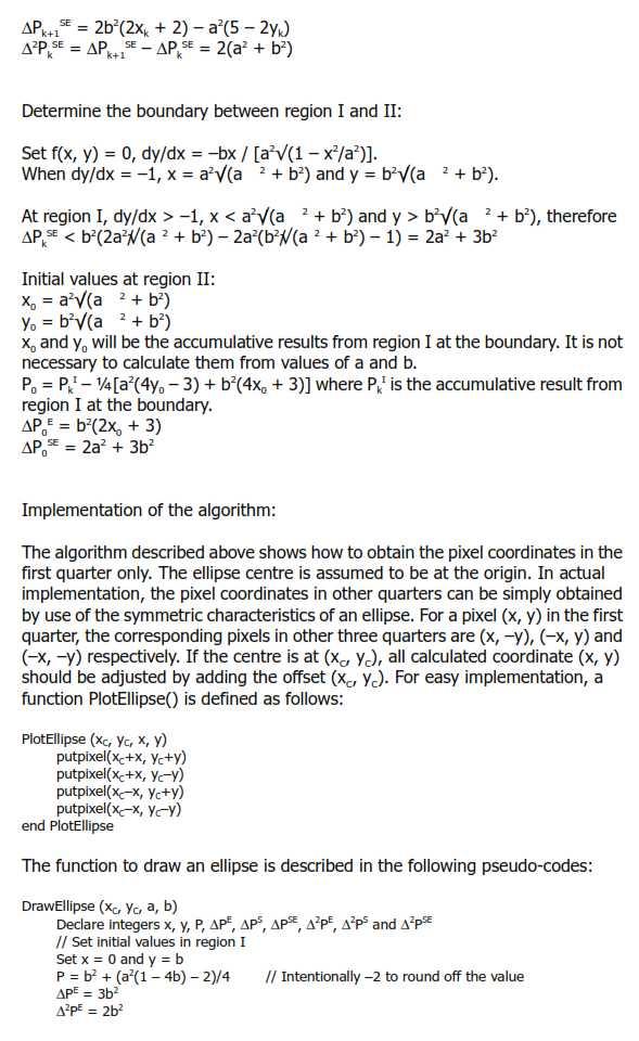
1 B. TECH. VI SEM. I MID TERM EXAMINATION 2018 BRANCH : COMPUTER SCIENCE ENGINEERING ( CSE ) SUBJECT : 6CS4A COMPUTER GRAPHICS & MULTIMEDIA TECHNIQUES Q 1. Write down mid point ellipse drawing algorithm. Also give proper explanation how to calculate points of each quadrant.
2
3
4
5
6 OR Q 1. Write down midpoint circle drawing algorithm. Also give proper explanation how to calculate points of each octants. Ans. We need to plot the perimeter points of a circle whose center co-ordinates and radius are given using the Mid-Point Circle Drawing Algorithm. We use the above algorithm to calculate all the perimeter points of the circle in the first octant and then print them along with their mirror points in the other octants. This will work only because a circle is symmetric about it s centre. The algorithm is very similar to the Mid-Point Line Generation Algorithm. Here, only the boundary condition is different. For any given pixel (x, y), the next pixel to be plotted is either (x, y+1) or (x-1, y+1). This can be decided by following the steps below. 1. Find the mid-point p of the two possible pixels i.e (x-0.5, y+1) 2. If p lies inside or on the circle perimeter, we plot the pixel (x, y+1), otherwise if it s outside we plot the pixel (x-1, y+1) Boundary Condition : Whether the mid-point lies inside or outside the circle can be decided by using the formula:- Given a circle centered at (0,0) and radius r and a point p(x,y) F(p) = x 2 + y 2 r 2 if F(p)<0, the point is inside the circle F(p)=0, the point is on the perimeter
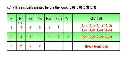
7 F(p)>0, the point is outside the circle In our program we denote F(p) with P. The value of P is calculated at the mid-point of the two contending pixels i.e. (x-0.5, y+1). Each pixel is described with a subscript k. P k = (X k 0.5) 2 + (y k + 1) 2 r 2 Now, x k+1 = x k or x k-1, y k+1 = y k +1 P k+1 = (x k+1 0.5) 2 + (y k+1 +1) 2 r 2 = (x k+1 0.5) 2 + [(y k +1) + 1] 2 r 2 = (x k+1 0.5) 2 + (y k +1) 2 + 2(y k + 1) + 1 r 2 = (x k+1 0.5) 2 + [ (x k 0.5) 2 +(x k 0.5) 2 ] + (y k + 1) 2 r 2 + (y k + 1) + 1 = P k + (x k+1 0.5) 2 (x k 0.5) 2 + 2(y k + 1) + 1 = P k + (x 2 k+1 x2 k ) 2 + (x k+1 x k ) 2 + 2(y k + 1) + 1 = P k + 2(y k +1) + 1, when P k <=0 i.e the midpoint is inside the circle (x k+1 = x k ) P k + 2(y k +1) 2(x k 1) + 1, when P k >0 I.e the mid point is outside the circle(x k+1 = x k -1) The first point to be plotted is (r, 0) on the x-axis. The initial value of P is calculated as follows:- P1 = (r 0.5) 2 + (0+1) 2 r 2 = 1.25 r = 1 -r (When rounded off) Examples: Input : Centre -> (0, 0), Radius -> 3 Output : (3, 0) (3, 0) (0, 3) (0, 3) (3, 1) (-3, 1) (3, -1) (-3, -1) (1, 3) (-1, 3) (1, -3) (-1, -3) (2, 2) (-2, 2) (2, -2) (-2, -2)
8
9 Q 2. Write down the DDA line drawing algorithm with proper explanation. Ans. In any 2-Dimensional plane if we connect two points (x0, y0) and (x1, y1), we get a line segment. But in the case of computer graphics we can not directly join any two coordinate points, for that we should calculate intermediate point s coordinate and put a pixel for each intermediate point, of the desired color with help of functions like putpixel(x, y, K) in C, where (x,y) is our co-ordinate and K denotes some color. Examples: Input: For line segment between (2, 2) and (6, 6) : we need (3, 3) (4, 4) and (5, 5) as our intermediate points. Input: For line segment between (0, 2) and (0, 6) : we need (0, 3) (0, 4) and (0, 5) as our intermediate points. For using graphics functions, our system output screen is treated as a coordinate system where the coordinate of the top-left corner is (0, 0) and as we move down our x-ordinate increases and as we move right our y-ordinate increases for any point (x, y). Now, for generating any line segment we need intermediate points and for calculating them we have can use a basic algorithm called DDA(Digital differential analyzer) line generating algorithm. DDA Algorithm: Consider one point of the line as (X0,Y0) and the second point of the line as (X1,Y1). // calculate dx, dy dx = X1 - X0; dy = Y1 - Y0; // Depending upon absolute value of dx & dy // choose number of steps to put pixel as // steps = abs(dx) > abs(dy)? abs(dx) : abs(dy) steps = abs(dx) > abs(dy)? abs(dx0 : abs(dy); // calculate increment in x & y for each steps Xinc = dx / (float) steps; Yinc = dy / (float) steps; // Put pixel for each step X = X0; Y = Y0; for (int i = 0; i <= steps; i++)
10 { } putpixel (X,Y,WHITE); X += Xinc; Y += Yinc;
11 OR Q 2. Describe the design and working of CRT with proper diagrams. Ans. Computer technology is going to see major advances in sophisticated 3 dimensional modeling and image processing; the users will see desktop computers with the computational power of today s super-computers. Even graphics capabilities would be available to the average user at a reasonable cost. To make this, an ultra high resolution monitors will be required. There are different display systems like cathode ray tubes (CRTs), liquid crystal displays (LCDs), electroluminescent displays (ELDs), plasma displays and light emitting diodes (LEDs) are available in the present technology. Here we are going to discuss about the Cathode Ray Tube (CRT). Principle of Working age When the two metal plates are connected to a high voltage source, the negatively charged plate called cathode, emits an invisible ray. The cathode ray is drawn to the positively charged plate, called the anode, where it passes through a hole and continues travelling to the other end of the tube. When the ray strikes the specially coated surface, the cathode ray produces a strong fluorescence, or bright light. When an electric field is applied across the cathode ray tube, the cathode ray is attracted by the plate bearing positive charges. Therefore a cathode ray must consist of negatively charged particles. A moving charged body behaves like a tiny magnet, and it can interact with an external magnetic field. The electrons deflected by the magnetic field. And also when the external magnetic field is reversed, the beam of electronics is deflected in the opposite direction. In a cathode ray tube, the cathode is a heated filament and it placed in vacuum. The ray is a stream of electrons that naturally pour off a heated cathode into the vacuum. Electrons are negative. The anode is positive, so it attracts the electrons pouring off the cathode. In a TV s cathode ray tube, the stream of electrons is focused by a focusing anode into a tight beam and then accelerated by an accelerating anode. This tight, high-speed beam of electrons flies through the vacuum in the tube and hits the flat screen at the other end of the tube. This screen is coated with phosphor, which glows when struck by the beam. Operation of CRT Cathode Ray Tube (CRT) is a computer display screen, used to display the output in a standard composite video signal. The working of CRT depends on movement of an electron beam which moves back and forth across the back of the screen. The source of the electron beam is the electron gun; the gun is located in the narrow, cylindrical neck at the extreme rear of a CRT which produces a stream of electrons through thermionic emission. Usually, A CRT has a fluorescent screen to display the output signal. A simple CRT is shown in below.
12 Cathode Ray Tube The operation of a CRT monitor is basically very simple. A cathode ray tube consists of one or more electron guns, possibly internal electrostatic deflection plates and a phosphor target. CRT has three electron beams one for each (Red, Green, and Blue) is clearly shown in figure. The electron beam produces a tiny, bright visible spot when it strikes the phosphor-coated screen. In every monitor device the entire front area of the tube is scanned repetitively and systematically in a fixed pattern called a raster. An image (raster) is displayed by scanning the electron beam across the screen. The phosphor s targets are begins to fade after a short time, the image needs to be refreshed continuously. Thus CRT produces the three color images which are primary colors. Here we used a 50 Hz rate to eliminate the flicker by refreshing the screen. Main parts of the cathode ray tube are cathode, control grid, deflecting plates and screen. Cathode The heater keeps the cathode at a higher temperature and electrons flow from the heated cathode towards the surface of the cathode. The accelerating anode has a small hole at its center and is maintained at a high potential, which is of positive polarity. The order of this voltage is 1 to 20 kv, relative to the cathode. This potential difference creates an electric field directed from right to left in the region between the accelerating anode and the cathode. Electrons pass through the hole in the anode travel with constant horizontal velocity from the anode to the fluorescent screen. The electrons strike the screen area and it glows brightly. The Control Grid The control grid regulates the brightness of the spot on the screen. By controlling the number of electrons by the anode and hence the focusing anode ensures that electrons leaving the cathode in slightly different directions are focused down to a narrow beam and all arrive at the same spot on the screen. The whole assembly of cathode, control grid, focusing anode, and accelerating electrode is called the electron gun. Deflecting Plates Two pairs of deflecting plates allow the beam of electrons. An electric field between the first pair of plates deflects the electrons horizontally, and an electric field between the second pair deflects them vertically, the
13 electrons travel in a straight line from the hole in the accelerating anode to the center of the screen when no deflecting fields are present, where they produce a bright spot. Screen This may be circular or rectangular. Screen is coated with special type of fluorescent material. Fluorescent material absorbs its energy and re-emits light in the form of photons when electron beam hits the screen. When it happens some of them bounces back just like bouncing of cricket ball from a wall. These are called as secondary electrons. They must be absorbed and returned back to cathode, if it is not so they accumulate near screen and produce space charge or electrons cloud. To avoid this, aquadag coating is applied on funnel part of CRT from inside. Advantages of CRT 1. CRT s are less expensive than other display technologies. 2. They operate at any resolution, geometry and aspect ratio without decreasing the image quality. 3. CRTs produce the very best color and gray-scale for all professional calibrations. 4. Excellent viewing angle. 5. It maintains good brightness and gives long life service. Q 3. What are the different techniques for producing color with a CRT, describe each in detail. Ans. This was one the earlier CRTs to produce color displays. Coating phosphors of different compounds can produce different colored pictures. But the basic problem of graphics is not to produce a picture of a predetermined color, but to produce color pictures, with the color characteristics chosen at run time. The basic principle behind colored displays is that combining the 3 basic colors Red, Blue and Green, can produce every color. By choosing different ratios of these three colors we can produce different colors millions of them in-fact. We also have basic phosphors, which can produce these basic colors. So, one should have a technology to combine them in different combinations. There are two popular techniques for producing color displays with a CRT are: Beam Penetration method This CRT is similar to the simple CRT, but it makes use of multi coloured phosphorus of number of layers. Each phosphorus layer is responsible for one colour. All other arrangements are similar to simple CRT. It can produce a maximum of 4 to 5 colours The organization is something like this - The red, green and blue phosphorus are coated in layers - one behind the other. If a low speed beam strikes the CRT, only the red colored phosphorus is activated, a slightly accelerated beam would activate both red and green (because it can penetrate deeper) and a much more activated one would add the blue component also. But the basic problem is a reliable technology to accelerate the electronic beam to precise levels to get the exact colors - it is easier said than done. However, a limited range of colors can be conveniently produced using the concept.

14 The Shadow - Mask method. This works, again, on the principle of combining the basic colors - Red, green and Blue - in suitable proportions to get a combination of colors, but it's principle is much more sophisticated and stable. The shadow mask CRT, instead of using one electron gun, uses 3 different guns placed one by the side of the other to form a triangle or a "Delta" as shown. Each pixel point on the screen is also made up of 3 types of phosphors to produce red, blue and green colors. Just before the phosphor screen is a metal screen, called a "shadow mask". This plate has holes placed strategically, so that when the beams from the three electron guns are focused on a particular pixel, they get focused on particular color producing pixel only i.e. If for convenience sake we can call the electronic beams as red, blue and green beams (though in practice the colors are produced by the phosphors, and until the beams hit the phosphor dots, they produce no colors), the metal holes focus the red beam onto the red color producing phosphor, blue beam on the blue producing one etc. When focused on to a different pixel, the red beam again focuses on to the red phosphor and so on. Now, unlike the beam penetration CRTs where the acceleration of the electron beam was being monitored, we now manipulate the intensity of the 3 beams simultaneously. If the red beam is made more intense, we get more of red color in the final combination etc. Since fine-tuning of the beam intensities is comparatively simple, we can get much more combination of colors than the beam penetration case. In fact, one can have a matrix of combinations to produce a wide variety of colors. The shadow mask CRT, though better than the beam penetration CRT in performance, is not without it's disadvantages. Since three beams are to be focused, the role of the "Shadow mask" becomes critical. If the focusing is not achieved properly, the results tend to be poor. Also, since instead of one pixel point in a monochrome CRT now each pixel is made up of 3 points (for 3 colors), the resolution of the CRT (no. of pixels) for a given screen size reduces. Another problem is that since the shadow mask blocks a portion of the beams (while focusing them through the holes) their intensities get reduced, thus reducing the overall brightness of the picture. To overcome this effect, the beams will have to be produced at very high intensities to begin with. Also, since the 3 color points, though close to each other, are still not at the same point, the pictures tend to look like 3 colored pictures placed close by, rather than a single picture. Of course, this effect can be reduced by placing the dots as close to one another as possible. The above displays are called refresh line drawing displays, because the picture vanishes (typically in about 100 Milli seconds ) and the pictures have to be continuously refreshed so that the human persistence of vision makes them see as static pictures. They are costly on one hand and also tend to flicker when complex pictures are displayed (Because refreshing because complex).
15 These problems are partly overcome by devices with inherent storage devices - i.e. they continue to display the pictures, till they are changed or at least for several minutes without the need of being refreshed. We see one such device called the Direct View Storage Tube (DVST) below.


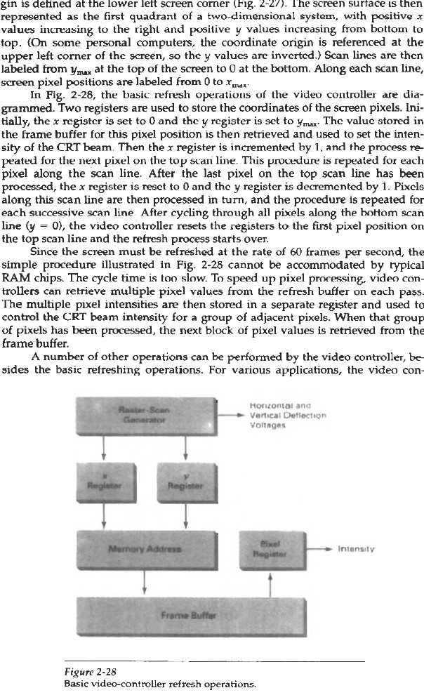
16 OR Q 3. Describe the concept of Video Controller Raster Scan System.
17
18 Q 4. What do you mean by Geometric Transformations? Describe following with Transformation matrix in homogeneous coordinate system. Translation Rotation Scaling HOMOGENEOUS COORDINATES We have seen that basic transformations can be expressed in matrix form. But many graphic application involve sequences of geometric transformations. Hence we need a general form of matrix to represent such transformations. This can be expressed as: Where P and P' - represent the row vectors. T 1 - is a 2 by 2 array containing multiplicative factors. - is a 2 element row matrix containing translation terms. T 2 We can combine multiplicative and translational terms for 2D geometric transformations into a single matrix representation by expanding the 2 by 2 matrix representations to 3 by 3 matrices. This allows us to express all transformation equations as matrix multiplications, providing that we also expand the matrix representations for coordinate positions. To express any 2D transformations as a matrix multiplication, we represent each Cartesian coordinate position (x,y) with the homogeneous coordinate triple (x h,y h,h), such that Thus, a general homogeneous coordinate representation can also be written as (h.x, h.y, h). For 2D geometric transformations, we can choose the homogeneous parameter h to any non-zero value. Thus, there is an infinite number of equivalent homogeneous representations for each coordinate point (x,y). A convenient choice is simply to h=1. Each 2D position is then represented with homogeneous coordinates (x,y,1). Other values for parameter h are needed, for eg, in matrix formulations of 3D viewing transformations. Expressing positions in homogeneous coordinates allows us to represent all geometric transformation equations as matrix multiplications. Coordinates are represented with three element row vectors and transformation operations are written as 3 by 3 matrices. For Translation, we have or
19 Similarly for Rotation transformation, we have or Finally for Scaling transformation, we have or Q 4. Write down Bresenhams' line drawing algorithm. OR Given coordinate of two points A(x1, y1) and B(x2, y2). The task to find all the intermediate points required for drawing line AB on the computer screen of pixels. Note that every pixel has integer coordinates. Examples: Input : A(0,0), B(4,4) Output : (0,0), (1,1), (2,2), (3,3), (4,4) Input : A(0,0), B(4,2) Output : (0,0), (1,0), (2,1), (3,1), (4,2) Below are some assumptions to keep algorithm simple. 1. We draw line from left to right. 2. x1 < x2 and y1< y2 3. Slope of the line is between 0 and 1. We draw a line from lower left to upper right. Let us understand the process by considering the naive way first.
20 // A naive way of drawing line void naivedrawline(x1, x2, y1, y2) { m = (y2 - y1)/(x2 - x1) for (x = x1; x <= x2; x++) { // Assuming that the round function finds // closest integer to a given float. y = round(mx + c); print(x, y); } } Above algorithm works, but it is slow. The idea of Bresenham's algorithm is to avoid floating point multiplication and addition to compute mx + c, and then computing round value of (mx + c) in every step. In Bresenham's algorithm, we move across the x-axis in unit intervals. 1. We always increase x by 1, and we choose about next y, whether we need to go to y+1 or remain on y. In other words, from any position (X k, Y k ) we need to choose between (X k + 1, Y k ) and (X k + 1, Y k + 1). 2. We would like to pick the y value (among Y k + 1 and Y k ) corresponding to a point that is closer to the original line. We need to a decision parameter to decide whether to pick Y k + 1 or Y k as next point. The idea is to keep track of slope error from previous increment to y. If the slope error becomes greater than 0.5, we know that the line has moved upwards one pixel, and that we must increment our y coordinate and readjust the error to represent the distance from the top of the new pixel which is done by subtracting one from error. // Modifying the naive way to use a parameter // to decide next y. void withdecisionparameter(x1, x2, y1, y2) { m = (y2 - y1)/(x2 - x1) slope_error = [Some Initial Value] for (x = x1, y = y1; x <= x2; x++) { print(x, y);
21 // Add slope to increment angle formed slope_error += m; // Slope error reached limit, time to increment // y and update slope error. if (slope_error >= 0.5) { y++; slope_error -= 1.0; } } } How to avoid floating point arithmetic The above algorithm still includes floating point arithmetic. To avoid floating point arithmetic, consider the value below value m. m = (y2 - y1)/(x2 - x1) We multiply both sides by (x2 - x1) We also change slope_error to slope_error * (x2 - x1). To avoid comparison with 0.5, we further change it to slope_error * (x2 - x1) * 2. Also, it is generally preferred to compare with 0 than 1. // Modifying the above algorithm to avoid floating // point arithmetic and use comparison with 0. void bresenham(x1, x2, y1, y2) { m_new = 2 * (y2 - y1) slope_error_new = [Some Initial Value] for (x = x1, y = y1; x <= x2; x++) { print(x, y); // Add slope to increment angle formed slope_error_new += m_new; // Slope error reached limit, time to increment // y and update slope error. if (slope_error_new >= 0) { y++; slope_error_new -= 2 * (x2 - x1); } } } The initial value of slope_error_new is 2*(y2 - y1) - (x2 - x1). Refer this for proof of this value Below is the implementation of above algorithm.


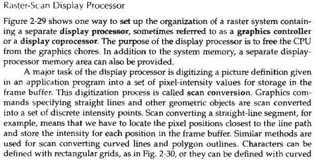
22 Q 5. Describe the concept of Display Processor in Raster Scan System.
23
24 OR Q 5. What do you mean by Composite Geometric Transformation? Find out the composite transformation matrix for translation, rotation and scaling.
25
Types of CRT Display Devices. DVST-Direct View Storage Tube
 Examples of Computer Graphics Devices: CRT, EGA(Enhanced Graphic Adapter)/CGA/VGA/SVGA monitors, plotters, data matrix, laser printers, Films, flat panel devices, Video Digitizers, scanners, LCD Panels,
Part 1: Introduction to Computer Graphics
 Part 1: Introduction to Computer Graphics 1. Define computer graphics? The branch of science and technology concerned with methods and techniques for converting data to or from visual presentation using
2.2. VIDEO DISPLAY DEVICES
 Introduction to Computer Graphics (CS602) Lecture 02 Graphics Systems 2.1. Introduction of Graphics Systems With the massive development in the field of computer graphics a broad range of graphics hardware
Computer Graphics: Overview of Graphics Systems
 Computer Graphics: Overview of Graphics Systems By: A. H. Abdul Hafez Abdul.hafez@hku.edu.tr, 1 Outlines 1. Video Display Devices 2. Flat-panel displays 3. Video controller and Raster-Scan System 4. Coordinate
Display Technologies CMSC 435. Slides based on Dr. Luebke s slides
 Display Technologies CMSC 435 Slides based on Dr. Luebke s slides Recap: Transforms Basic 2D Transforms: Scaling, Shearing, Rotation, Reflection, Composition of 2D Transforms Basic 3D Transforms: Rotation,
CATHODE-RAY OSCILLOSCOPE (CRO)
") CATHODE-RAY OSCILLOSCOPE (CRO) I N T R O D U C T I O N : The cathode-ray oscilloscope (CRO) is a multipurpose display instrument used for the observation, measurement, and analysis of waveforms by plotting
CATHODE-RAY OSCILLOSCOPE (CRO) I N T R O D U C T I O N : The cathode-ray oscilloscope (CRO) is a multipurpose display instrument used for the observation, measurement, and analysis of waveforms by plotting
Comp 410/510. Computer Graphics Spring Introduction to Graphics Systems
 Comp 410/510 Computer Graphics Spring 2018 Introduction to Graphics Systems Computer Graphics Computer graphics deals with all aspects of 'creating images with a computer - Hardware (PC with graphics card)
These are used for producing a narrow and sharply focus beam of electrons.
 CATHOD RAY TUBE (CRT) A CRT is an electronic tube designed to display electrical data. The basic CRT consists of four major components. 1. Electron Gun 2. Focussing & Accelerating Anodes 3. Horizontal
Display Systems. Viewing Images Rochester Institute of Technology
 Display Systems Viewing Images 1999 Rochester Institute of Technology In This Section... We will explore how display systems work. Cathode Ray Tube Television Computer Monitor Flat Panel Display Liquid
Computer Graphics : Unit - I
 Computer Graphics Unit 1 Introduction: Computer Graphics it is a set of tools to create, manipulate and interact with pictures. Data is visualized through geometric shapes, colors and textures. Video Display
CMPE 466 COMPUTER GRAPHICS
 1 CMPE 466 COMPUTER GRAPHICS Chapter 2 Computer Graphics Hardware Instructor: D. Arifler Material based on - Computer Graphics with OpenGL, Fourth Edition by Donald Hearn, M. Pauline Baker, and Warren
Part 1: Introduction to computer graphics 1. Describe Each of the following: a. Computer Graphics. b. Computer Graphics API. c. CG s can be used in
 Part 1: Introduction to computer graphics 1. Describe Each of the following: a. Computer Graphics. b. Computer Graphics API. c. CG s can be used in solving Problems. d. Graphics Pipeline. e. Video Memory.
CHAPTER 3 OSCILLOSCOPES AND SIGNAL GENERATOR
 CHAPTER 3 OSCILLOSCOPES AND SIGNAL GENERATOR OSCILLOSCOPE 3.1 Introduction The cathode ray oscilloscope (CRO) provides a visual presentation of any waveform applied to the input terminal. The oscilloscope
CS2401-COMPUTER GRAPHICS QUESTION BANK
 SRI VENKATESWARA COLLEGE OF ENGINEERING AND TECHNOLOGY THIRUPACHUR. CS2401-COMPUTER GRAPHICS QUESTION BANK UNIT-1-2D PRIMITIVES PART-A 1. Define Persistence Persistence is defined as the time it takes
Computer Graphics Hardware
 Computer Graphics Hardware Kenneth H. Carpenter Department of Electrical and Computer Engineering Kansas State University January 26, 2001 - February 5, 2004 1 The CRT display The most commonly used type
CHAPTER 4 OSCILLOSCOPES
 CHAPTER 4 OSCILLOSCOPES 4.1 Introduction The cathode ray oscilloscope generally referred to as the oscilloscope, is probably the most versatile electrical measuring instrument available. Some of electrical
THE OPERATION OF A CATHODE RAY TUBE
 THE OPERATION OF A CATHODE RAY TUBE OBJECT: To acquaint the student with the operation of a cathode ray tube, and to study the effect of varying potential differences on accelerated electrons. THEORY:
The Cathode Ray Tube
 Lesson 2 The Cathode Ray Tube The Cathode Ray Oscilloscope Cathode Ray Oscilloscope Controls Uses of C.R.O. Electric Flux Electric Flux Through a Sphere Gauss s Law The Cathode Ray Tube Example 7 on an
CATHODE RAY OSCILLOSCOPE. Basic block diagrams Principle of operation Measurement of voltage, current and frequency
 CATHODE RAY OSCILLOSCOPE Basic block diagrams Principle of operation Measurement of voltage, current and frequency 103 INTRODUCTION: The cathode-ray oscilloscope (CRO) is a multipurpose display instrument
PTIK UNNES. Lecture 02. Conceptual Model for Computer Graphics and Graphics Hardware Issues
 E3024031 KOMPUTER GRAFIK E3024032 PRAKTIK KOMPUTER GRAFIK PTIK UNNES Lecture 02 Conceptual Model for Computer Graphics and Graphics Hardware Issues 2014 Learning Objectives After carefully listening this
CATHODE RAY OSCILLOSCOPE (CRO)
") CATHODE RAY OSCILLOSCOPE (CRO) 4.6 (a) Cathode rays CORE Describe the production and detection of cathode rays Describe their deflection in electric fields State that the particles emitted in thermionic
CATHODE RAY OSCILLOSCOPE (CRO) 4.6 (a) Cathode rays CORE Describe the production and detection of cathode rays Describe their deflection in electric fields State that the particles emitted in thermionic
Sep 09, APPLICATION NOTE 1193 Electronic Displays Comparison
 Sep 09, 2002 APPLICATION NOTE 1193 Electronic s Comparison Abstract: This note compares advantages and disadvantages of Cathode Ray Tubes, Electro-Luminescent, Flip- Dot, Incandescent Light Bulbs, Liquid
THE OPERATION OF A CATHODE RAY TUBE
 THE OPERATION OF A CATHODE RAY TUBE OBJECT: To acquaint the student with the operation of a cathode ray tube, and to study the effect of varying potential differences on accelerated electrons. THEORY:
MODULE I MCA COMPUTER GRAPHICS ADMN APPLICATIONS OF COMPUTER GRAPHICS
 MODULE 1 1. APPLICATIONS OF COMPUTER GRAPHICS Computer graphics is used in a lot of areas such as science, engineering, medicine, business, industry, government, art, entertainment, advertising, education
Display Devices & its Interfacing
 Display Devices & its Interfacing 3 Display systems are available in various technologies such as i) Cathode ray tubes (CRTs), ii) Liquid crystal displays (LCDs), iii) Plasma displays, and iv) Light emitting
L14 - Video. L14: Spring 2005 Introductory Digital Systems Laboratory
 L14 - Video Slides 2-10 courtesy of Tayo Akinwande Take the graduate course, 6.973 consult Prof. Akinwande Some modifications of these slides by D. E. Troxel 1 How Do Displays Work? Electronic display
Reading. Display Devices. Light Gathering. The human retina
 Reading Hear & Baker, Computer graphics (2 nd edition), Chapter 2: Video Display Devices, p. 36-48, Prentice Hall Display Devices Optional.E. Sutherland. Sketchpad: a man-machine graphics communication
Electrical & Electronic Measurements: Class Notes (15EE36) Module-5. Display Devices
 Module-5. Display Devices") Module-5 Display Devices Syllabus: Introduction Character formats Segment displays Dot matrix displays Bar graph displays Cathode ray tubes Light emitting diodes Liquid crystal displays Nixies Incandescent
Module-5 Display Devices Syllabus: Introduction Character formats Segment displays Dot matrix displays Bar graph displays Cathode ray tubes Light emitting diodes Liquid crystal displays Nixies Incandescent
OSCILLOSCOPE AND DIGITAL MULTIMETER
 Exp. No #0 OSCILLOSCOPE AND DIGITAL MULTIMETER Date: OBJECTIVE The purpose of the experiment is to understand the operation of cathode ray oscilloscope (CRO) and to become familiar with its usage. Also
1. Introduction. 1.1 Graphics Areas. Modeling: building specification of shape and appearance properties that can be stored in computer
 1. Introduction 1.1 Graphics Areas Modeling: building specification of shape and appearance properties that can be stored in computer Rendering: creation of shaded images from 3D computer models 2 Animation:
Screens; media that use additive primaries
 Image display Display is the final stage in the image processing pipeline: Continuous scenes are acquired and digitally processed. The display process essentially converts the discrete image back to continuous
Monitor and Display Adapters UNIT 4
 Monitor and Display Adapters UNIT 4 TOPIC TO BE COVERED: 4.1: video Basics(CRT Parameters) 4.2: VGA monitors 4.3: Digital Display Technology- Thin Film Displays, Liquid Crystal Displays, Plasma Displays
decodes it along with the normal intensity signal, to determine how to modulate the three colour beams.
 Television Television as we know it today has hardly changed much since the 1950 s. Of course there have been improvements in stereo sound and closed captioning and better receivers for example but compared
Displays. History. Cathode ray tubes (CRTs) Modern graphics systems. CSE 457, Autumn 2003 Graphics. » Whirlwind Computer - MIT, 1950
 Modern graphics systems. CSE 457, Autumn 2003 Graphics. » Whirlwind Computer - MIT, 1950") History Displays CSE 457, Autumn 2003 Graphics http://www.cs.washington.edu/education/courses/457/03au/» Whirlwind Computer - MIT, 1950 CRT display» SAGE air-defense system - middle 1950 s Whirlwind II
History Displays CSE 457, Autumn 2003 Graphics http://www.cs.washington.edu/education/courses/457/03au/» Whirlwind Computer - MIT, 1950 CRT display» SAGE air-defense system - middle 1950 s Whirlwind II
3. Displays and framebuffers
 3. Displays and framebuffers 1 Reading Required Angel, pp.19-31. Hearn & Baker, pp. 36-38, 154-157. Optional Foley et al., sections 1.5, 4.2-4.5 I.E. Sutherland. Sketchpad: a man-machine graphics communication
Computer Graphics Prof. Sukhendu Das Dept. of Computer Science and Engineering Indian Institute of Technology, Madras Lecture - 5 CRT Display Devices
 Computer Graphics Prof. Sukhendu Das Dept. of Computer Science and Engineering Indian Institute of Technology, Madras Lecture - 5 CRT Display Devices Hello everybody, welcome back to the lecture on Computer
Elements of a Television System
 1 Elements of a Television System 1 Elements of a Television System The fundamental aim of a television system is to extend the sense of sight beyond its natural limits, along with the sound associated
VARIOUS DISPLAY TECHNOLOGIESS
 VARIOUS DISPLAY TECHNOLOGIESS Mr. Virat C. Gandhi 1 1 Computer Department, C. U. Shah Technical Institute of Diploma Studies Abstract A lot has been invented from the past till now in regards with the
Reading. Displays and framebuffers. Modern graphics systems. History. Required. Angel, section 1.2, chapter 2 through 2.5. Related
 Reading Required Angel, section 1.2, chapter 2 through 2.5 Related Displays and framebuffers Hearn & Baker, Chapter 2, Overview of Graphics Systems OpenGL Programming Guide (the red book ): First four
Downloads from: https://ravishbegusarai.wordpress.com/download_books/
 1. The graphics can be a. Drawing b. Photograph, movies c. Simulation 11. Vector graphics is composed of a. Pixels b. Paths c. Palette 2. Computer graphics was first used by a. William fetter in 1960 b.
Reading. 1. Displays and framebuffers. History. Modern graphics systems. Required
 Reading Required 1. Displays and s Angel, pp.19-31. Hearn & Baker, pp. 36-38, 154-157. OpenGL Programming Guide (available online): First four sections of chapter 2 First section of chapter 6 Optional
Basically we are fooling our brains into seeing still images at a fast enough rate so that we think its a moving image.
 Basically we are fooling our brains into seeing still images at a fast enough rate so that we think its a moving image. The formal definition of a Moving Picture... A sequence of consecutive photographic
1 Your computer screen
 U.S.T.H.B / C.E.I.L Unit 7 Computer science L2 (S2) 1 Your computer screen Discuss the following questions. 1 What type of display do you have? 2 What size is the screen? 3 Can you watch TV on your PC
Objectives: Topics covered: Basic terminology Important Definitions Display Processor Raster and Vector Graphics Coordinate Systems Graphics Standards
 MODULE - 1 e-pg Pathshala Subject: Computer Science Paper: Computer Graphics and Visualization Module: Introduction to Computer Graphics Module No: CS/CGV/1 Quadrant 1 e-text Objectives: To get introduced
Introduction to Computer Graphics
 Introduction to Computer Graphics R. J. Renka Department of Computer Science & Engineering University of North Texas 01/16/2010 Introduction Computer Graphics is a subfield of computer science concerned
Tutorial Cathode Rays Year 12 Physics - Module 9.3 Motors and Generators
 Tutorial 9.4.1.2 Cathode Rays Year 12 Physics - Module 9.3 Motors and Generators For use with Lesson 9.4.1 Cathode Rays 1. Identify the properties of cathode rays that indicated that they might be particles.
Lecture Flat Panel Display Devices
 Lecture 13 6.111 Flat Panel Display Devices Outline Overview Flat Panel Display Devices How do Displays Work? Emissive Displays Light Valve Displays Display Drivers Addressing Schemes Display Timing Generator
A Review- on Different Types of Displays
 , pp.327-332 http://dx.doi.org/10.14257/ijmue.2016.11.8.33 A Review- on Different Types of Displays Shubham Shama 1, Udita Jindal 2, Mehul Goyal 3, Sahil Sharma 4 and Vivek Goyal 5 1-4Department of ECE,
Introduction & Colour
 Introduction & Colour Eric C. McCreath School of Computer Science The Australian National University ACT 0200 Australia ericm@cs.anu.edu.au Overview Computer Graphics Uses Basic Hardware and Software Colour
2.4.1 Graphics. Graphics Principles: Example Screen Format IMAGE REPRESNTATION
 2.4.1 Graphics software programs available for the creation of computer graphics. (word art, Objects, shapes, colors, 2D, 3d) IMAGE REPRESNTATION A computer s display screen can be considered as being
INSTRUMENT CATHODE-RAY TUBE
 Instrument cathode-ray tube D14-363GY/123 INSTRUMENT CATHODE-RAY TUBE mono accelerator 14 cm diagonal rectangular flat face internal graticule low power quick heating cathode high brightness, long-life
Lecture Flat Panel Display Devices
 Lecture 1 6.976 Flat Panel Display Devices Outline Overview of 6.976 Overview Flat Panel Display Devices Course website http://hackman.mit.edu Reading Assignment: Article by Alt and Noda, IBM Journal of
RICHLAND COLLEGE School of Engineering Business & Technology Rev. 0 W. Slonecker Rev. 1 (8/26/2012) J. Bradbury
 J. Bradbury") RICHLAND COLLEGE School of Engineering Business & Technology Rev. 0 W. Slonecker Rev. 1 (8/26/2012) J. Bradbury INTC 1307 Instrumentation Test Equipment Teaching Unit 8 Oscilloscopes Unit 8: Oscilloscopes
RICHLAND COLLEGE School of Engineering Business & Technology Rev. 0 W. Slonecker Rev. 1 (8/26/2012) J. Bradbury INTC 1307 Instrumentation Test Equipment Teaching Unit 8 Oscilloscopes Unit 8: Oscilloscopes
DISPLAY TECHNOLOGIES. Group 6: Steve Lenhart, Ryan King, Ramsey Akl, and Andrew Scheib
 DISPLAY TECHNOLOGIES Group 6: Steve Lenhart, Ryan King, Ramsey Akl, and Andrew Scheib DISPLAY TECHNOLOGIES Group 6: Steve Lenhart, Ryan King, Ramsey Akl, and Andrew Scheib Introduction First computers
INSTRUMENT CATHODE-RAY TUBE
 INSTRUMENT CATHODE-RAY TUBE 14 cm diagonal rectangular flat face domed mesh post-deflection acceleration improved spot quality for character readout high precision by internal permanent magnetic correction
J.J. Thomson, Cathode Rays and the Electron
 Introduction Experimenters had noticed that sparks travel through rarefied (i.e. low pressure) air since the time of Franklin. The basic setup was to have two metal plates inside a glass tube. The air
Technology White Paper Plasma Displays. NEC Technologies Visual Systems Division
 Technology White Paper Plasma Displays NEC Technologies Visual Systems Division May 1998 1 What is a Color Plasma Display Panel? The term Plasma refers to a flat panel display technology that utilizes
Television brian egan isnm 2004
 Introduction Mechanical early developments. Electrical how it works. Digital advantages over analogue. brian egan isnm Mechanical television First televisions were mechanical based on revolving disc, first
Computer Graphics. Raster Scan Display System, Rasterization, Refresh Rate, Video Basics and Scan Conversion
 Computer Graphics Raster Scan Display System, Rasterization, Refresh Rate, Video Basics and Scan Conversion 2 Refresh and Raster Scan Display System Used in Television Screens. Refresh CRT is point plotting
Teltron Delection Tube D
 Teltron Delection Tube D 1011119 Overview The electron-beam deflection tube is intended for investigating the deflection of electron beams in electrical and magnetic fields. It can be used to estimate
UNIT 1 INTRODUCTION TO COMPUTER
 UNIT 1 INTRODUCTION TO COMPUTER Introduction to Computer Structure 1.1 Introduction Objectives 1.2 Display Devices 1.2.1 Cathode Ray Tube Technology (CRT) 1.2.2 Random Scan Display 1.2.3 Raster Scan Display
Presented by: Amany Mohamed Yara Naguib May Mohamed Sara Mahmoud Maha Ali. Supervised by: Dr.Mohamed Abd El Ghany
 Presented by: Amany Mohamed Yara Naguib May Mohamed Sara Mahmoud Maha Ali Supervised by: Dr.Mohamed Abd El Ghany Analogue Terrestrial TV. No satellite Transmission Digital Satellite TV. Uses satellite
An Efficient SOC approach to Design CRT controller on CPLD s
 A Monthly Peer Reviewed Open Access International e-journal An Efficient SOC approach to Design CRT controller on CPLD s Abstract: Sudheer Kumar Marsakatla M.tech Student, Department of ECE, ACE Engineering
Computer Graphics. Introduction
 Computer Graphics Introduction Introduction Computer Graphics : It involves display manipulation and storage of pictures and experimental data for proper visualization using a computer. Typically graphics
High-resolution screens have become a mainstay on modern smartphones. Initial. Displays 3.1 LCD
 3 Displays Figure 3.1. The University of Texas at Austin s Stallion Tiled Display, made up of 75 Dell 3007WPF LCDs with a total resolution of 307 megapixels (38400 8000 pixels) High-resolution screens
CR7000. CRT Analyzer & Restorer. Easily Test And Restore CRTs With The Most Complete Tests Available For Added Profit And Security.
 CR7000 CRT Analyzer & Restorer Easily Test And Restore CRTs With The Most Complete Tests Available For Added Profit And Security. S1 New Demands From Higher Performance CRTs Require New Analyzing Techniques
K Service Source. Apple High-Res Monochrome Monitor
 K Service Source Apple High-Res Monochrome Monitor K Service Source Specifications Apple High-Resolution Monochrome Monitor Specifications Characteristics - 1 Characteristics Picture Tube 12-in. diagonal
General Items: Reading Materials: Miscellaneous: Lecture 8 / Chapter 6 COSC1300/ITSC 1401/BCIS /19/2004. Tests? Questions? Anything?
 General Items: Tests? Questions? Anything? Reading Materials: Miscellaneous: F.Farahmand 1 / 14 File: lec7chap6f04.doc What is output? - A computer processes the data and generates output! - Also known
Electrical and Electronic Laboratory Faculty of Engineering Chulalongkorn University. Cathode-Ray Oscilloscope (CRO)
") 2141274 Electrical and Electronic Laboratory Faculty of Engineering Chulalongkorn University Cathode-Ray Oscilloscope (CRO) Objectives You will be able to use an oscilloscope to measure voltage, frequency
2141274 Electrical and Electronic Laboratory Faculty of Engineering Chulalongkorn University Cathode-Ray Oscilloscope (CRO) Objectives You will be able to use an oscilloscope to measure voltage, frequency
Overview of Graphics Systems
 CHAPTER - 2 Overview of Graphics Systems Video Display Devices Instructions are stored in a display memory display file display list Modes: immediate each element is processed and displayed retained objects
This work was supported by FINEP (Research and Projects Financing) under contract
 under contract") MODELING OF A GRIDDED ELECTRON GUN FOR TRAVELING WAVE TUBES C. C. Xavier and C. C. Motta Nuclear & Energetic Research Institute, São Paulo, SP, Brazil University of São Paulo, São Paulo, SP, Brazil Abstract
MODELING OF A GRIDDED ELECTRON GUN FOR TRAVELING WAVE TUBES C. C. Xavier and C. C. Motta Nuclear & Energetic Research Institute, São Paulo, SP, Brazil University of São Paulo, São Paulo, SP, Brazil Abstract
FUNDAMENTAL CONSTRUCTION OF A CRT
 Presented at the Electronic Media Group Session, AIC 40th Annual Meeting, May 8 11, 2012, Albuquerque, NM. FUNDAMENTALS OF THE CATHODE RAY TUBE BASED DISPLAY AND ITS MAINTENANCE AND CONSERVATION WITHIN
Module 7. Video and Purchasing Components
 Module 7 Video and Purchasing Components Objectives 1. PC Hardware A.1.11 Evaluate video components and standards B.1.10 Evaluate monitors C.1.9 Evaluate and select appropriate components for a custom
Chapter 3. Display Devices and Interfacing
 Chapter 3 Display Devices and Interfacing Monitor Details Collection of dots Matrix of dots creates character Monochrome monitor screen is collection of 350 *720 350 rows and each rows having 720 dots
K Service Source. Apple High-Res Monochrome Monitor
 K Service Source Apple High-Res Monochrome Monitor K Service Source Specifications Apple High-Resolution Monochrome Monitor Specifications Characteristics - 1 Characteristics Picture Tube 12-in. diagonal
Design of VGA Controller using VHDL for LCD Display using FPGA
 International OPEN ACCESS Journal Of Modern Engineering Research (IJMER) Design of VGA Controller using VHDL for LCD Display using FPGA Khan Huma Aftab 1, Monauwer Alam 2 1, 2 (Department of ECE, Integral
CS 4451A: Computer Graphics. Why Computer Graphics?
 CS 445A: Computer Graphics z CCB, TT 9:3- Why Computer Graphics? z Fun! z Lots of uses: y Art, entertainment y Visualizing complex data/ideas y Concise representation of actions/commands/state y Design/task
Understanding Multimedia - Basics
 Understanding Multimedia - Basics Joemon Jose Web page: http://www.dcs.gla.ac.uk/~jj/teaching/demms4 Wednesday, 9 th January 2008 Design and Evaluation of Multimedia Systems Lectures video as a medium
The Knowledge Bank at The Ohio State University. Ohio State Engineer
 The Knowledge Bank at The Ohio State University Ohio State Engineer Title: Creators: Principles of Electron Tubes Lamoreaux, Yvonne Issue Date: 1944-03 Publisher: Ohio State University, College of Engineering
VGA Port. Chapter 5. Pin 5 Pin 10. Pin 1. Pin 6. Pin 11. Pin 15. DB15 VGA Connector (front view) DB15 Connector. Red (R12) Green (T12) Blue (R11)
 DB15 Connector. Red (R12) Green (T12) Blue (R11)") Chapter 5 VGA Port The Spartan-3 Starter Kit board includes a VGA display port and DB15 connector, indicated as 5 in Figure 1-2. Connect this port directly to most PC monitors or flat-panel LCD displays
Chapter 5 VGA Port The Spartan-3 Starter Kit board includes a VGA display port and DB15 connector, indicated as 5 in Figure 1-2. Connect this port directly to most PC monitors or flat-panel LCD displays
INSTALATION PROCEDURE
 INSTALLATION PROCEDURE Overview The most difficult part of an installation is in knowing where to start and the most important part is starting in the proper start. There are a few very important items
Light Emitting Diodes (LEDs)
") Light Emitting Diodes (LEDs) Example: Circuit symbol: Function LEDs emit light when an electric current passes through them. Connecting and soldering LEDs must be connected the correct way round, the diagram
Light Emitting Diodes (LEDs) Example: Circuit symbol: Function LEDs emit light when an electric current passes through them. Connecting and soldering LEDs must be connected the correct way round, the diagram
PAST EXAM PAPER & MEMO N3 ABOUT THE QUESTION PAPERS:
 EKURHULENI TECH COLLEGE. No. 3 Mogale Square, Krugersdorp. Website: www. ekurhulenitech.co.za Email: info@ekurhulenitech.co.za TEL: 011 040 7343 CELL: 073 770 3028/060 715 4529 PAST EXAM PAPER & MEMO N3
Brown, A., Merkert, J., & Wilson, R. (2014). Build your own particle accelerator. Science in School, (30),
. Build your own particle accelerator. Science in School, (30),") Brown, A., Merkert, J., & Wilson, R. (2014). Build your own particle accelerator. Science in School, (30), 21-26. Publisher's PDF, also known as Version of record License (if available): CC BY-NC-SA Link
Brown, A., Merkert, J., & Wilson, R. (2014). Build your own particle accelerator. Science in School, (30), 21-26. Publisher's PDF, also known as Version of record License (if available): CC BY-NC-SA Link
MODIFYING A SMALL 12V OPEN FRAME INDUSTRIAL VIDEO MONITOR TO BECOME A 525/625 & 405 LINE MULTI - STANDARD MAINS POWERED UNIT. H. Holden. (Dec.
 MODIFYING A SMALL 12V OPEN FRAME INDUSTRIAL VIDEO MONITOR TO BECOME A 525/625 & 405 LINE MULTI - STANDARD MAINS POWERED UNIT. H. Holden. (Dec. 2017) INTRODUCTION: Small open frame video monitors were made
3B SCIENTIFIC PHYSICS
 3B SCIENTIFIC PHYSICS Complete Fine Beam Tube System 1013843 Instruction sheet 10/15 SD/ALF If it is to be expected that safe operation is impossible (e.g., in case of visible damage), the apparatus is
CHAPTER 9. Actives Devices: Diodes, Transistors,Tubes
 CHAPTER 9 Actives Devices: Diodes, Transistors,Tubes 1 The electrodes of a semiconductor diode are known as anode and cathode. In a semiconductor diode, electrons flow from cathode to anode. In order for
Introduction. Edge Enhancement (SEE( Advantages of Scalable SEE) Lijun Yin. Scalable Enhancement and Optimization. Case Study:
 Lijun Yin. Scalable Enhancement and Optimization. Case Study:") Case Study: Scalable Edge Enhancement Introduction Edge enhancement is a post processing for displaying radiologic images on the monitor to achieve as good visual quality as the film printing does. Edges
Case Study: Scalable Edge Enhancement Introduction Edge enhancement is a post processing for displaying radiologic images on the monitor to achieve as good visual quality as the film printing does. Edges
THE CAPABILITY to display a large number of gray
 292 JOURNAL OF DISPLAY TECHNOLOGY, VOL. 2, NO. 3, SEPTEMBER 2006 Integer Wavelets for Displaying Gray Shades in RMS Responding Displays T. N. Ruckmongathan, U. Manasa, R. Nethravathi, and A. R. Shashidhara
Using an oscilloscope - The Hameg 203-6
 Using an oscilloscope - The Hameg 203-6 What does an oscilloscope do? Setting up How does an oscilloscope work? Other oscilloscope controls Connecting a function generator Microphones audio signals and
Start with some basics: display devices
 Output Concepts Start with some basics: display devices Just how do we get images onto a screen? Most prevalent device: CRT Cathode Ray Tube AKA TV tube 2 Cathode Ray Tubes Cutting edge 1930 s technology
Flat Panel Displays: 1. Introduction
 OSE-6820 Flat Panel Displays: 1. Introduction Prof. Shin-Tson Wu College of Optics & Photonics University of Central Florida Email: swu@mail.ucf.edu Office: CREOL 280 Phone: 407-823-4763 UCF College of
Secrets of the Studio. TELEVISION CAMERAS Technology and Practise Part 1 Chris Phillips
 Secrets of the Studio TELEVISION CAMERAS Technology and Practise Part 1 Chris Phillips Television Cameras Origins in Film Television Principles Camera Technology Studio Line-up Developments Questions of
Duke University. Plasma Display Panel. A vanished technique
 Duke University Plasma Display Panel A vanished technique Yida Chen Dr. Hubert Bray Math 190s: Mathematics of the Universe 31 July 2017 Introduction With the establishment of the atomic theory, we begin
28 North Lotts, Dublin 1, Ireland Tel: info [AT] phonevolts.com
![28 North Lotts, Dublin 1, Ireland Tel: info [AT] phonevolts.com](/thumbs/91/104995975.jpg "28 North Lotts, Dublin 1, Ireland Tel: info [AT] phonevolts.com") www.phonevolts.ie 28 North Lotts, Dublin 1, Ireland Tel: 01 8728722 Email: info [AT] phonevolts.com PhoneVolts is owned and operated by GSMsolutions.ie What is an LCD? A liquid crystal display (commonly
www.phonevolts.ie 28 North Lotts, Dublin 1, Ireland Tel: 01 8728722 Email: info [AT] phonevolts.com PhoneVolts is owned and operated by GSMsolutions.ie What is an LCD? A liquid crystal display (commonly
Video Display Unit (VDU)
") Video Display Unit (VDU) Historically derived from Cathode Ray Tube (CRT) technology Based on scan lines Horizontal flyback Vertical flyback Blank Active video Blank (vertical flyback takes several line
Video Display Unit (VDU) Historically derived from Cathode Ray Tube (CRT) technology Based on scan lines Horizontal flyback Vertical flyback Blank Active video Blank (vertical flyback takes several line
Liquid Crystal Display (LCD)
") Liquid Crystal Display (LCD) When coming into contact with grooved surface in a fixed direction, liquid crystal molecules line up parallelly along the grooves. When coming into contact with grooved surface
Liquid Crystal Display (LCD) When coming into contact with grooved surface in a fixed direction, liquid crystal molecules line up parallelly along the grooves. When coming into contact with grooved surface
University of Utah Electrical & Computer Engineering Department ECE1050/1060 Oscilloscope
 University of Utah Electrical & Computer Engineering Department ECE1050/1060 Oscilloscope Name:, A. Stolp, 2/2/00 rev, 9/15/03 NOTE: This is a fill-in-the-blanks lab. No notebook is required. You are encouraged
Correlation to the Common Core State Standards
 Correlation to the Common Core State Standards Go Math! 2011 Grade 4 Common Core is a trademark of the National Governors Association Center for Best Practices and the Council of Chief State School Officers.
Video coding standards
 Video coding standards Video signals represent sequences of images or frames which can be transmitted with a rate from 5 to 60 frames per second (fps), that provides the illusion of motion in the displayed