CPX Rugged Military Grade 6U Rack Mount 17.3-Inch Wide-Screen LCD Display
|
|
|
- Damian Carr
- 5 years ago
- Views:
Transcription


1 CPX2-173 Rugged Military Grade 6U Rack Mount 17.3-Inch Wide-Screen LCD Display Technical Reference A Revision Preliminary A June 4, 2014
2 Warranty The product is warranted against material and manufacturing defects for two years from date of delivery. Buyer agrees that if this product proves defective Chassis Plans is only obligated to repair, replace or refund the purchase price of this product at Chassis Plans discretion. The warranty is void if the product has been subjected to alteration, neglect, misuse or abuse; if any repairs have been attempted by anyone other than Chassis Plans; or if failure is caused by accident, acts of God, or her causes beyond the control of Chassis Plans. Chassis Plans reserves the right to make changes or improvements in any product without incurring any obligation to similarly alter products previously purchased. In no event shall Chassis Plans be liable for any defect in hardware or software or loss or inadequacy of data of any kind, or for any direct, indirect, incidental or consequential damages arising out of or in connection with the performance or use of the product or information provided. Chassis Plans liability shall in no event exceed the purchase price of the product purchased hereunder. The foregoing limitation of liability shall be equally applicable to any service provided by Chassis Plans. Return Policy Products returned for repair must be accompanied by a Return Material Authorization (RMA) number, obtained from Chassis Plans prior to return. Freight on all returned items must be prepaid by the customer, and the customer is responsible for any loss or damage caused by common carrier in transit. Items will be returned from Chassis Plans via Ground, unless prior arrangements are made by the customer for an alternative shipping method To obtain an RMA number, call us at We will need the following information: Return company address and contact Model name and model # from the label on the back of the display Serial number from the label on the back of the display Description of the failure An RMA number will be issued. Mark the RMA number clearly on the outside of each box, include a failure report for each board and return the product(s) to our San Diego, CA facility: Chassis Plans Carroll Canyon Road San Diego, CA Attn: Repair Department

3 Trademarks Liability Disclaimer The Original Industrial Computer Source, Systems Engineered to Perform and Chassis Plans are registered trademarks of Chassis Plans, LLC. IBM, PC/AT, VGA, EGA, OS/2 and PS/2 are trademarks or registered trademarks of International Business Machines Corp. Intel is a registered trademark of Intel Corporation. MS-DOS and Microsoft are registered trademarks of Microsoft Corp. All other brand and product names may be trademarks or registered trademarks of their respective companies. This manual is as complete and factual as possible at the time of printing; however, the information in this manual may have been updated since that time. Chassis Plans reserves the right to change the functions, features or specifications of their products at any time, without notice. Copyright 2014 by Chassis Plans. All rights reserved. Support@chassisplans.com Web: Chassis Plans Carroll Canyon Road San Diego, CA Phone: (858) Fax: (858) Saleseng@chassisplans.com
4 This Page Intentionally Blank
5 I ndex Table of Contents Chapter 1 Introduction 1 Description 1 Table 1 Display Specifications 1 LCD Enhancements 2 Figure 1 EMI Shielding Effectiveness of ITO Coating 2 Figure 2 Optical Stack on LCD 2 Figure 3 Comparison of Reflections with and without Optical Bonding 3 Figure 4 Comparison with and without Optical Bonding 3 Genesis Based LCD Controllers 4 Figure 5 Controller Specifications 4 Photos 5 Specifications 6 Enclosure 6 Display 6 Display Enhancement Options 6 Power Supply Options 6 Environmental 6 Table 2 Specifications 6 Figure 6 CCX Outline Drawing 7 Chapter 2 Power Supply Options 9 AC Input Power Supply 9 Table 3 AC Input Supply Specifications 9 Photo 1 AC Power Supply 9 12VDC Input Transient Filter 10 Connectors 10 MIL STD 704/ VDC DC Input 11 Operating Specifications 11 Connectors 11 Environmental Specifications 11 Table 4 MIL STD 704 Power Supply Specifications 11 +/ 48VDC Power Supply 12 Operating Specifications 12 Connectors 12 Electrical Specifications 12 Table 5 48VDC Power Supply Specifications 12 Chapter 3 Ordering Information 13 Part Number Matrix 13 Example Part Numbers 13 Chapter 4 Installation 15 Package Contents 15 Table 6 Package Contents 15 Rack Installation 16 Figure 7 Rack Mounting Hole Spacing 16
6 I ndex Connecting the Display 17 Standard Controller Rear Panel Connections 17 Photo 2 Standard Controller Rear Panel I/O 17 Table 7 Rear Panel Connections Standard Controller 17 Advanced Controller Rear Panel Connections 18 Photo 3 Advanced HD/SDI Controller Rear Panel I/O 18 Table 8 Rear Panel Connections Advanced HD/SDI Controller 18 Chapter 5 Operation 19 LCD Front Panel Controls 19 Table 9 Front Panel Controls 19 Standard Controller OSD Menus 20 Advanced HD/SDI Controller OSD Menus 25 Appendix A Display Serial Control Programming 27 RS 232 Serial control 27 Controller Serial Control Functions 27 Table 10 Standard Controller Commands to Implement Switch Mount Control Buttons 27 Table 11 Standard Controller Parameter Setting Immediate, Relative, and 28 Table 12 Standard Controller Other Control 38 Table 13 Hex to ASCII Conversion Table 40 Appendix B Auto Color Gain 41 Image B 1 Auto Color Gain Example 41 Appendix C DVI D versus DVI I Connectors 42 Overview 42 Connectors 42 Appendix D Ethernet Network Connection 43 Connecting a network port to CPX Get the IP address using DHCP 44 Web Console 44 IP Locator 44 Image D 1 IP Locator Screen Show 44 Network configuration 44 Image D 2 Network Drop Down 44 Image D 3 Network Configure Settings 45 Connect to a single CPX Table D 1 Remote Control 45 Image D 4 IP Address Locator 46 Image D 5 IP Address Setting and Enable 46 Connect to multiple CPX Table D 2 Remote Control 46 Image D 6 DHCP Table Screenshot 47 Image D 7 NAT Fowarding Screenshot 47
7 Chapter 1 - Introduction Chapter 1 - Introduction Description The CPX2-173 is a military-grade high-performance 6U rack mount or panel mount LCD display offering 1920 x 1080 wide-screen high-definition resolution. The CPX2-173 is designed to meet Mil-Std 901D and MIL-STD- 810G and includes a solid milled aluminum front panel, lightweight 5052-H32 aluminum construction and locking stainless hardware throughout. The CPX2-173 is ideal for mounting in a transit case for adverse environments that would destroy lesser displays. Two versions offer standard brightness or hi-bright for sunlight visibility. CPX Standard CPX Hi-Bright Contrast Ratio 600:1 600:1 Viewing Angle (L/R/U/D) 80º 80º Response Time 40ms 40ms Brightness 400 cd/m cd/m 2 Backlight LED LED Native Resolution 1920 x x 1080 Aspect Ratio 16:9 16:9 Table 1 Display Specifications The displays are high-performance, long life TFT LCD s offering a maximum native wide-screen resolution of 1920 x The displays offer optional optically bonded anti-reflective overlay glass. In addition, an optional laminated 1.1mm soda lime glass with an ITO conductive EMI filter and an additional 1.1mm soda lime glass overlay with anti-reflective (AR) coating. Both glass components are optically bonded to each other, and to the front of the display, for superior viewing clarity and overall ruggedness. A 6mm copper bus bar surrounds the entire glass stack-up and provides consistent grounding. A contrast ratio of approximately 1300:1 is delivered with this ITO/Anti-Reflective glass stack-up. The front surface is an oleophobic anti-reflective coating resistant to fingerprints. The displays offer 16.7 million colors (True Color). The displays provide multiple signal input options including argb, DVI-D, HDMI, Display Port, HD-SDI, NTSC, S-Video and Composite Video, depending on the controller. The displays offer a choice of high quality advanced scaling controllers with a Genesis chipset. These are specifically ruggedized controllers offering as standard conformal coating with high shock/vibration and temperature extreme tolerances as well as long life product availability for assured delivery throughout multi-year programs. The Standard Controller offers DVI-D, VGA (argb), HDMI, NTSC and CVS. In addition, the Standard Controller supports Picture-In-Picture (PIP) and Picture-By-Picture. The Advanced HD-SDI Controller offers VGA (argb), HDMI, Display Port, HD-SDI and 3G HD-SDI. The display is only 6U (10.47-inches) high offering significant rack space savings. It can be rack mounted, panel mounted, or mounted using a VESA adapter via the included VESA hole pattern on the rear of the unit. It is only 2.75-inches deep and power and signal cables exit down so as to not increase depth requirements. As with all Chassis Plans products, a wide variety of custom options can be configured per customer or application specific requirements. Contact your Sales Engineer to discuss your particular requirements. Page 1
8 Chapter 1 - Introduction LCD Enhancements Chassis Plans starts with Grade A Industrial Quality LCD panels selected for optical performance, high reliability and long product life cycle. In order to not only ruggedize the LCD, but to also enhance the mechanical, optical and EMI properties of the finished unit, as an option, Chassis Plans optically bonds one 3mm anti-reflective or two layers of coated 1.1 mm soda-lime float glass to the front of the LCD panel. The first layer is coated with an Indium Tin Oxide (ITO) coating with a surface resistivity of <13.5 ohms/sq. See Figure 1 for attenuation values MHz 75 MHz 100 MHz 150 MHz 200 MHz 300 MHz 500 MHz 700 MHz 1000 MHz 15" LCD 17" LCD 19" LCD Figure 1 EMI Shielding Effectiveness of ITO Coating There is a Copper conductive buss bar that wraps around the edge of the glass to facilitate conduction from the ITO coating to the front surface of the laminated structure to make a complete electrical shield around the face of the LCD. See Figure 2 for details. Copper Buss Bar AR Coating Optical Index Matching Adhesive Soda Lime Float Glass ITO Coating LCD Panel And Backlight LCD Frame Figure 2 Optical Stack on LCD The second layer of glass is coated with an Oleophobic Anti-Reflective (AR) coating which matches the index of refraction of air to eliminate surface reflections. These layers of coated glass are bonded together with an index matching optical adhesive to eliminate internal reflections caused by the index of refraction mismatch between the soda lime glass and air. This eliminates over 95% of unwanted glare from the screen. Please see Figure 3 below for more details. Page 2


9 Without Optical Bonding Or AR Coating With Optical Bonding And AR Coating Chapter 1 - Introduction 4.5% 4.5% 4.5% Reflected Light Total 22.5% 0.3% 0.1% 0.1% Reflected Light Total 0.7% 4.5% 0.1% 4.5% 0.1% Figure 3 Comparison of Reflections with and without Optical Bonding The resulting structure in conjunction with the CPX Hi-Bright 1000nit panel has greatly enhanced optical characteristics in high ambient light conditions. The optical adhesive used is a silicone RTV and offers other benefits mechanically to the LCD as well. The adhesive remains pliable and therefore acts as a shock absorbing medium for the front of the LCD. Together with the additional layers of glass provides a very rugged composite structure. Another benefit is that should breakage actually occur the shards of glass will be retained together to prevent injury to personnel. The adhesive also prevents any condensation from building up in the air gap between the layers of glass which would cause fogging of the display. Finally, the added mass bonded to the front of the LCD display adds a thermal conduction path to help dissipate the heat generated in the backlights themselves. By eliminating the majority of reflected light, the apparent contrast improves making the display more readable in high bright situations. An alternative to improving the contrast is to increase the back light levels to overpower the reflected light. The downside to this approach is the higher power requirements and higher heat generated by the backlights. Photo Courtesy of GDS Clearview Figure 4 Comparison with and without Optical Bonding Page 3

10 Chapter 1 - Introduction Genesis Based LCD Controllers The LCD Controller is a key component in any display system and no expense has been spared in specifying the Standard Controller and Advanced HD-SDI Controller Genesis controllers. These are long life revision controlled military grade components. The Genesis chip set is the current gold standard for LCD controllers. The controllers support 3x8-bit 16.7 million colors at up to 1920 x Refresh rates of 60Hz for WUXGA and UXGA with higher refresh rates for lower resolutions available. Computer input signals of VGA, SVGA, XGA, SXGA, WXGA, UXGA and WUXGA are supported. Video inputs of NTSC, PAL and SECAM are optionally available. DVI inputs supports up to 1920 x 1080 WUXGA 60Hz signals. These ruggedized military grade controllers are rated for operating at -40 to +80 deg C, use low mass tantalum capacitors for maximum vibration and shock tolerance and are conformal coated for extreme ruggedness. The coating is silicone resin conformal coating.(mod) DEF- STAN 59/47 Issue 4 &UL QMJU2 compliant MTBF for the controllers is in excess of 150,000 to 200,000 hours. Figure 5 Controller Specifications Page 4


11 Chapter 1 - Introduction Photos Connector details dependent on installed controller Page 5
12 Specifications Enclosure 6U (10.47 ) x 3.2 deep Front Panel milled 5052 aluminum alloy Body made of 5052-H32 aluminum alloy All stainless steel hardware All self-locking pressed in fasteners where appropriate Powder coat black, medium texture, for ruggedness Other colors optionally available Designed to Mil-Spec Standards to Satisfy Military, Industrial and Commercial Requirements Compact Enclosure for Limited Depth Installation Weight: 9.7lbs (depending on model & features) Display 17.3" Wide-Screen TFT LCD 1920 x 1080 Display Colors: 16.7 Million Response Time: 40ms Typical Viewing Angle: 80 deg Contrast Ratio: 600:1 typical native Brightness: 400cd/m2 standard (CPX2-1731), 1000cd/m2 enhanced daylight visibility (CPX2-1732) Pixel Pitch: mm x mm Pixel Arrangement: R.G.B Stripe Display Enhancement Options 3mm smudge-resistant anti-reflective coated soda lime float glass,bonded to the LCD panel with optical index matched adhesive Laminate of 1.1mm smudge-resistant anti-reflective coated soda lime float glass panel and a 1.1 mm ITO coated glass panel(<12.5ω/sq) grounded via a copper buss bar, bonded to the LCD panel with optical index matched adhesive Environmental (Designed to meet or exceed) Altitude 10,000 ft. Operational, 30,000 ft. Storage MIL-STD-810, Method High Temperature 70 C Operational, 70 C Storage MIL-STD-810, Method Low Temperature 0 C Operational, -20 C Storage MIL-STD-810, Method Humidity 5-95%, Non-condensing MIL-STD-810, Method Blowing Sand and Dust Procedures I and II MIL-STD-810, Method Chapter 1 - Introduction Transport Vibration US Highway Truck and Air Transport MIL-STD-810, Method Bench Handling Shock Procedure VI, 11ms MIL-STD-810, Method Power Supply Options AC Input 100 to 260VAC, auto selecting HZ 12VDC Input Transient Filter Line transient protection for 12VDC vehicular applications Mil-Std-1275A DC/DC Converter True 1275 compliance for military 28VDC nominal vehicle inputs 18 to 36VDC input 48VDC DC/DC Converter 36 to 75VDC Input Isolated Inputs for +/- input levels See the appropriate power supply section for complete power supply specifications. Table 2 Specifications Page 6
13 Chapter 1 - Introduction Figure 6 - CCX Outline Drawing Page 7
14 Chapter 1 - Introduction This Page Intentionally Blank Page 8

15 Chapter 2 Power Supply Options Chapter 2 Power Supply Options AC Input Power Supply The AC Input Power Supply is a 65W Medical Grade Brick style power supply. The output is provided with a circular mil connector for connecting to the LCD Keyboard Drawer. The input accepts a standard IEC 320 plug. A bracket is provided to securely mount the supply in a rack. Alternate AC supplies are available as required by the application or environmental requirements. INPUT Voltage Current Frequency Input Connector VAC VAC Hz 3-Pin IEC 320 Receptacle OUTPUT Voltage 12VDC Max Current 12.5A Total Regulation < +/- 5% Set Point Accuracy < +/- 60% Load Hold-up Time Full Load, 115VAC Over Voltage Protection Built-in Over Current Protection Built-in Short Circuit Protection Pulsing mode, auto recovery ENVIRONMENTAL Operating Temperature 0 to 50 C Storage Temperature -40 to +85 C SAFETY ctuvus UL CSA C22.2 No M90 CB per IEC CE marked to LVD Class I EMI/EMC Emissions CISPR11 and FCC Part 15, Class B EN , -3 Immunity EN , -3, -4, -5, -6, -9, -11 SIZE L X W X H 7.56 x 2.45 x 1.52 Weight 1.55 lbs Table 3 - AC Input Supply Specifications Photo 1 - AC Power Supply Page 9
16 Chapter 2 Power Supply Options 12VDC Input Transient Filter The CPX2-173 display consoles require nominal +12VDC at 40W for operation. An EMI line filter is provided to limit EMI emissions and to provide a small measure of input filtering. For operation from unregulated 12VDC (+/-10%) such as in a vehicular or marine environment, front end transient filtering is required to suppress potentially damaging spikes from large inductive loads in the DC circuit (starters, etc.). The xxx 12VDC Input Transient Filter provides an input Transient Protection as well as inductive and capacitive filtering to suppress large input transients. A bridge rectifier provides reverse connection protection. A circuit breaker provides for failure protection and allows the power to be disconnected. Connectors Input Connector Mating Input Connector Pinouts Output Connector Mating Output Connector Pinouts MS3102A-10SL-3P (MIL-C-5015) MS3106A-10SL-3S (Straight) MS3108A-10SL-3S (Right Angle) Pin A Positive Pin B Negative Input Pin C N/C MS3102A-10SL-3S (MIL-C-5015) MS3106A-10SL-3S (Straight) MS3108A-10SL-3S (Right Angle) Pin A Positive Pin B Negative Pin C N/C Page 10
17 Chapter 2 Power Supply Options MIL-STD-704/ VDC DC Input The C option 28VDC Mil-Std-704/1275 DC Input is an internal power supply providing true 704/1275 input specifications allowing reliable operation from nominal 28VDC input mains in a military environment. This supply meets Mil-Std-704A and Mil-Std-1275A (100V for 50mS). Operating Specifications Input Voltage Output Voltage Output Current Output Power 18-36VDC 12.0VDC 5A 75W Electrical Specifications Efficiency 81% Isolation 200VDC, Input to Output and Input to Case EMI Filtering Mil-Std-461E, CD101 and CE102 on the input Operating Temperature -40 C to +85 C Storage Temperature -55 C to +100 C Connectors Input Connector Mating Input Connector Pinouts Output Connector Mating Output Connector Pinouts MS3102A-10SL-4P (MIL-C-5015) MS3106A-10SL-4S (Straight) MS3108A-10SL-4S (Right Angle) Pin A Positive Pin B Negative Pin C N/C MS3102A-10SL-3S (MIL-C-5015) MS3106A-10SL-3S (Straight) MS3108A-10SL-3S (Right Angle) Pin A Positive Pin B Negative Pin C N/C Environmental Specifications Pressure-Altitude Per MIL-STD-810F, Method 500.4, Procedure I and II High Temperature Per MIL-STD-810F, Method 501.4, Procedure I and II Low Temperature Per MIL-STD-810F, Method 502.4, Procedure I Humidity Per MIL-STD-810F, Method 507.4, Procedure I Fungus Per Mil-Std-810F, Method 508.5, Procedure I Salt Fog Per Mil-Std-810F, Method 509.4, Procedure I Sand and Dust Per Mil-Std-810F, Method 510.4, Procedure I and II Explosive Atmosphere Per Mil-Std-810F, Method 511.4, Procedure I Acceleration Per MIL-STD-810F, Method 513.5, Procedure I and II Vibration Per MIL-STD-810F, Method 514.5, Procedure I, Category 1, 4, 7 thru 14 and 16 thru 21 Shock Per MIL-STD-810F, Method 516.5, Procedure I, IV Table 4 - MIL-STD-704 Power Supply Specifications Page 11
18 Chapter 2 Power Supply Options +/-48VDC Power Supply The xx 48VDC Input Converter provides universal isolated 48VDC input, either positive or negative input. Thus it can be used in a data center with centralized power of +48VDC as well as a central office with -48VDC mains. The system is provided in a rack mountable case with military grade circular connectors. Operating Specifications Input Voltage Output Voltage Output Current Output Power Connectors Input Connector Mating Input Connector Pinouts Output Connector Mating Output Connector Pinouts 36-75VDC 12.0VDC 10A 120W MS3102A-14SL-7P (MIL-C-5015) MS3106A-14S-7S (Straight) MS3108A-14S-7S (Right Angle) Pin A - Positive Pin B Negative MS3102A-10SL-3S (MIL-C-5015) MS3106A-10SL-3S (Straight) MS3108A-10SL-3S (Right Angle) Pin A Positive Pin B Negative Pin C N/C Electrical Specifications Efficiency 92% Isolation 1500VDC, Input to Output and Input to Case EMI Filtering Mil-Std-461E, CD101 and CE102 on the input Operating Temperature -40 C to +85 C Storage Temperature -55 C to +125 C Table 5-48VDC Power Supply Specifications Page 12
19 Chapter 3 Ordering Information Chapter 3 Ordering Information Part Number Matrix CPX2-173[M][ME][S][P]) (M) Standard or Hi-Bright Monitor 1 Standard 600 cd/m2 2 Hi-Bright 1,000 cd/m2 (ME) LCD Surface Enhancements A Bonded EMI Filter and AR cover glass B Standard w/ no screen enhancements C - Bonded 3mm AR coated cover glass E - Bonded USB Resistive touch screen (S) Video Signal Inputs D4 Includes VGA, DVI-D, HDMI, Component, Composite G1 - VGA, Dispay Port, HDMI, Component, Composite, HD-SDI (P) Power Supply Option N No supply provided. Operates from nominal 12VDC +/-5% A AC input, universal VAC, 50/60Hz B 12VDC Front End Transient Filter C 28VDC Mil-Std-704 Military Grade D 12VDC for connection to Chassis Plans Chassis Power Plug E +/-48VDC, Vicor Module Military Grade F AC input, universal VAC, 400Hz Example Part Numbers CPX2-1731BD4A Standard brightness. No LCD enhancements. VGA/DVI/HDMI input. AC Power. CPX2-1732CG1C Hi-Bright display brightness. Anti-reflective LCD enhancement. Enhanced HD/SDI controller. 28VDC input power. Page 13
20 Chapter 3 Ordering Information This Page Intentionally Blank Page 14
21 Chapter 4 - Installation Chapter 4 - Installation Package Contents Part Description Quanty LCD Keyboard Assembly 1 Power Supply 1 (if P/S spec d in part number) Power Supply Rack Bracket 1 (if P/S spec d in part number) Rack Ruler 1 Rack Slide Hardware Kit (General Devices) 1 Cable Tie, 7-9/16 Long 8 Velcro Tie, Black 6 Cage Nuts 8 Manual, LCD User, CD 1 Manual, LCD Quick Start Guide 1 Checklist 1 DVI Cable, 6-Foot 1 VGA Cable, 6-Foot 1 USB A-A Cable, 6-Foot 1 PS/2 Keyboard/Mouse Cable, 6-Foot 2 Table 6 - Package Contents Notes: 1. Power Cord Kit For the AC input supplies, a standard 6-foot North American IEC-320 power cord is provided. For the DC input supplies, a kit is provided with a mating Mil Circular connector, backshell, and pins allowing the user to fabricate an appropriate cable for the intended application. For volume orders, Chassis Plans can provide pre-fabricated power cables per the end use specifications. Page 15
22 Chapter 4 - Installation Rack Installation To mount the CPX2-173 in a rack, it is first important you identify the correct holes to mount to. Please see the following illustration. Note that a U starts between the holes that are ½ apart. One very common problem is trying to install into the wrong holes. Because there are multiple styles of racks, it is not possible to provide detailed instructions on mounting the equipment. However, there are general instructions at for rack installation which should help. Figure 7 - Rack Mounting Hole Spacing Chassis Plans offer free Rack Rulers to assist in installing equipment into racks. You should have received one with your order. To request more, fill out the short form at and we ll send you as many as you want. These are invaluable for installing systems into racks. Page 16


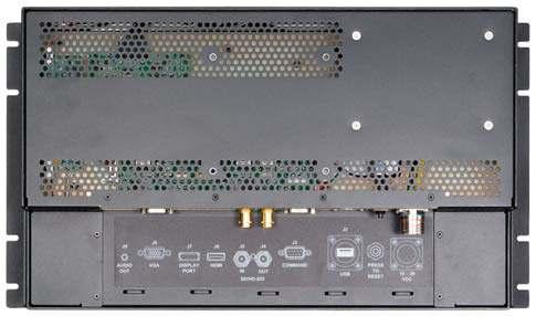
23 Chapter 4 - Installation Connecting the Display The CPX2-173 provide for two controllers with rear panel details provided below. Standard Controller Rear Panel Connections The Standard Controller provides for DVI and VGA inputs. In addition, the rear of the display provides for Keyboard and Pointing Device outputs plus a Circular Mil connector for power connection. The Standard Controller offers the following features: Inputs: Analog RGB: DVI-D/HDMI: 60Hz at WUXGA, UXGA 75Hz at SXGA, WXGA, XGA, SVGA, VGA With auto detect of Digital Separate Sync, Sync-On-Green & Composite Sync. Auto detects VGA-WUXGA, interlaced & non-interlaced 60Hz at WUXGA 75Hz at SXGA, WXGA, XGA, SVGA, VGA Image Scaling: Up / down scaling to fit input to native panel resolution of 1280x1024. Video: NTSC /PAL/SECAM (Interlaced), Composite Video, S-video, SD Component (YCbCr), HD Component (YPbPr) Image Control: Brightness, Contrast, Saturation, Hue, Frequency, Phase, Color temperature, Image position, Hue, Gamma. Other Features: Auto picture setup, Auto RGB calibration, Auto source seek, OSD timeout, OSD position, Input source select, OSD menu lock, Direct key for brightness level adjustment. Photo 2 Standard Controller Rear Panel I/O Legend Function Connector VGA argb Input HD15 Female Display Port Display Port Input Display Port HDMI HDMI Input HDMI SDI Input HD/SDI Input BNC Reclocked SDI Output HD/SDI Reclocked Output BNC RS232 Control Port RS232 Remote Control DB9 Female Touch Screen Touch Screen Output USB USBFTV22G (Optional) 12VDC Power Input Power, 12VDC +/-5% Circular Mil N/S 3102A-10SL-3P Circuit Breaker Power Interruption Push to reset Table 7 - Rear Panel Connections Standard Controller Page 17
 allowing a video input (Composite or S-Video) image to be laid on top of either a VGA or DVI input.")

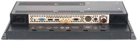
24 Chapter 4 - Installation Advanced Controller Rear Panel Connections The Advanced Controller provides for HD/SDI, VGA analog, HDMI, Display PortComposite and S-Video video inputs. The Advanced Controller also supports Picture-In-Picture (PIP) allowing a video input (Composite or S-Video) image to be laid on top of either a VGA or DVI input. The Advanced HD/SDI Controller offers the following features: Inputs: Analog RGB: 60Hz at WUXGA, UXGA, SXGA, WXGA, XGA, SVGA, VGA With auto detect of Digital Separate Sync,Sync-On-Green & Composite Sync. Auto detects VGA-WUXGA, interlaced & non-interlaced HDMI 1.3: 60Hz at WUXGA, UXGA, SXGA, WXGA, XGA, SVGA, VGA, 1080p, 1080i, 720p, 576p, 480p Display: 60Hz at WUXGA, UXGA, SXGA, WXGA, XGA, SVGA, VGA, 1080p, 1080i, 720p, 576p, 480p Port 1.1a SDI: 576i50 (PAL), 480i60 (NTSC), 720p60/59.94/50 (4:2:2), 1080i60/59.94/50 (4:2:2), Features: 1080p60/50 (4:2:2) Image Up-Scaling, Image Down-Scaling, Auto picture setup, Auto RGB calibration, Auto source seek, OSD timeout, OSD position, OSD menu rotation, OSD transparency, select input source, Volume control, On board temperature reporting Image Control: Brightness, Contrast, Sharpness, Color, Clock, Phase, Color temperature, Image position, Gamma SDI Reclocked Output Touch Display SDI Input RS232 Control Screen* Circuit VGA Port HDMI Port Breaker Power Photo 3 - Advanced HD/SDI Controller Rear Panel I/O Legend Function Connector VGA argb Input HD15 Female Display Port Display Port Input Display Port HDMI HDMI Input HDMI SDI Input HD/SDI Input BNC Reclocked SDI Output HD/SDI Reclocked Output BNC RS232 Control Port RS232 Remote Control DB9 Female Touch Screen Touch Screen Output USB USBFTV22G (Optional) 12VDC Power Input Power, 12VDC +/-5% Circular Mil N/S 3102A-10SL-3P Circuit Breaker Power Interruption Push to reset Table 8 - Rear Panel Connections Advanced HD/SDI Controller Page 18
25 Chapter 5 Operation & OSDs Chapter 5 - Operation LCD Front Panel Controls The On Screen Display (OSD) is adjusted as follows: 1. Press the Menu Button located on the front of the monitor. 2. Use the buttons described below to maneuver around the Menu. 3. Select the desired OSD Menu from the Menu Screen Shots below to make the desired adjustment(s). 4. Press the Menu button to exit out of the OSD Menu when complete or wait for the OSD window to automatically close as set by the OSD Time Out setting. Power: Turns the Unit On and Off Adjust : o Hot Key 1 Increase o When the cursor is not showing in sub menus, moves selection right between top tabs. o Cursor showing in sub menus, adjusts setting up. o Cursor on sub-sub menu ( showing), enters sub-sub menu. (See Select below to escape). o Toggles Off to On Adjust : o Hot Key 1 Decrease o When the cursor is not showing in sub menus, moves selection left between top tabs. o Cursor showing in sub menus, adjust setting down o Toggles On to Off Select : o Hot Key 2 Increase o Moves the cursor up. o When in a sub-sub menu, repeatedly press to move to the previous menu level. (See Adjust above) Select : o Hot Key 2 Decrease. o Moves the cursor Down. Menu o Opens or closes the OSD menu o See Note 1 below for additional information. Brightness : o Increases the screen brightness. Brightness : o Decreases the screen brightness. Green Normal Operation Red Power On but no input signal Off No power or display turned off Hot Keys Hot Keys are defined in the Utility/Hot Key menu and allow single button access to the defined function. Adjust and - Hot Key 1 Up and Down Select and - Hot Key 2 Up and Down Display Auto Adjust Pressing Auto/Exit will perform a auto display adjustment when in argb mode. This automatically adjusts the Phase and Clock for the est displayed image. To save your changes, press the front panel Menu button. Alternatively, changes are saved if no buttons are pressed and the OSD times out returning back to the display. Notes On the Menu Buttons 1. The Menus are context sensitive in that only adjustments pertaining to the selected input will be displayed. For example, if DVI is selected for the input, then items such as Hue will not be adjustable. 2. Pressing the Menu button returns to the previously opened menu. Notes on Hot Keys - 1. Hot Keys allow single button selection of a function. 2. Definition of the Hot Keys is set in the Utility menu. Thus, for example, if the Adjust keys are set up for Input Source, pushing the Up button rolls Up through the Input Sources and pushing the Down button rolls Down through the Input Sources. 3. The Hot Keys display in the upper left of the screen when pushed. Note on Factory Default 1. Under the Utilities Menu, a selection is available to return the board setting to the factory defaults. Table 9 - Front Panel Controls Page 19

26 Chapter 5 Operation & OSDs Standard Controller OSD Menus Page 20
27 Chapter 5 Operation & OSDs Page 21
28 Chapter 5 Operation & OSDs Page 22
29 Chapter 5 Operation & OSDs Page 23
30 Chapter 5 Operation & OSDs Page 24

31 Chapter 5 Operation & OSDs Advanced HD/SDI Controller OSD Menus Page 25

32 Chapter 5 Operation & OSDs Page 26
33 Appendix A Display Serial Control Programming Appendix A Display Serial Control Programming Both LCD controllers provide for remote serial RS232 control through the rear panel Control Port as shown below. The Standard Controller also provides for control through an Ethernet port. The following command set remains the same for Ethernet control as compared to Serial control. RS-232 Serial control Baud rate 2400, 8 bits, 1 stop bit and no parity Mating face of RS-232 DB9 Male 5 PIN# Description 2 RS-232 Rx Data 3 RS-232 Tx Data 5 Ground Mating connector : DB9 Female Controller Serial Control Functions The OSD functions are controlled through the following RS-232 commands. The RS-232 program can be custom-tailored to fit the application or it can be used as provided by Chassis Plans on request. Please contact Chassis Plans for additional information. Note: Not all Serial Control functions are supported in the Advanced HD/SDI controller. In the following table, functions not supported for the Advanced HD/SDI Controller are indicated with a * in the Function column. Table 10 - Standard Controller Commands to Implement Switch Mount Control Buttons Function Command Description Acknowledge (if enabled) OSD Menu Lock 0xf6 OSD menu Lock Off / OSD Button equivalent menu Lock On Menu 0xf7 Menu button pressed Button equivalent Select-down 0xfa Select down button pressed Button equivalent button Select-up button 0xfb Select up button pressed Button equivalent Right/+ button 0xfc Right/+button pressed Button equivalent Left/- button 0xfd Left/- button pressed Button equivalent Page 27
34 Appendix A Display Serial Control Programming Table 11 - Standard Controller Parameter Setting - Immediate, Relative, and Function Command Description Acknowledge (if enabled) Volume control - volume left+right channel Volume control - on/off (mute) 0x80, a A, nn + - 0x80, m M, 0 1 Brightness control 0x81, nn + - m n i, ss, nn o, ss, Contrast control - all channels 0x82, a A, nn + - m n i, ss, nn o, ss, Saturation control* 0x83, nn + - m n i, ss, nn o, ss, Hue control* 0x84, nn + - m n i, ss, nn o, ss, Phase (tuning) control 0x85, nn + - Image H position 0x86, nnnn + - Set audio (L+R) volume = Disable audio output. Enable audio output. Set brightness = Current Source Maximum query *1 Minimum query *1 Set, Source, value *1, Source *1 Set all contrast = Maximum query *1 Minimum query *1 Set, Source, value *1, Source *1 Set color = Maximum query *1 Minimum query *1 Set, Source, value *1, Source *1 Set tint = Maximum query *1 Minimum query *1 Set, Source, value *1, Source *1 Set dot clock phase = Set img_hpos = Range : E Default : 0 F 0 - audio off (muted). 1 - audio on. Brightness. Range : 4 E - B 2 Default : 8 0 ss - reference by Input main select(0x98) Contrast Range : 1 C - E 4 Default : 8 0 ss - reference by Input main select(0x98) PAL/NTSC color (In video mode only ) Range : F F Default : 8 0 ss - reference by Input main select(0x98) NTSC tint (In NTSC mode only) Range : F Default : 7 9 ss - reference by Input main select(0x98) Dot clock phase. (In PC mode only) Image horizontal position. (In PC mode only) # - Function in ARGB mode only * - Implemented only in standard controller. Not applicable to Advanced HD/SDI Controller. Page 28
35 Appendix A Display Serial Control Programming Image V position 0x87, nnnn + - Sharpness 0x8a, nn + - Frequency 0x8b, nnnn + - Scaling Mode* 0x8c, A B C D OSD H position 0x90, nnn + - OSD V position 0x91, nnn + - OSD Transparency* OSD menu timeout Select OSD Language* 0x92, n + - 0x93, nn + - 0x95, n Input main select 0x98, nn + - Set img_vpos = Set sharpness = Set frequency = Value/increment/decrement Set graphic image scaling mode = value Set osd_hpos = Set osd_vpos = Set OSD transparency = Select menu timeout = Select language = English, Chinese, Select input main = PC or VIDEO or next available Image vertical position. (In PC mode only) Sharpness. (Video Mode Source only) Range : F 4-0 C Default : 0 0 Graphic mode H active size (in pixels) Image expansion on/off. 0 1:1 1 fill screen 2 fill to aspect ratio 9 4:3 A 16:9 B 16:10 C 2.35:1 D 2:1 OSD horizontal position. Range : F F Default : 8 0 OSD vertical position. Range : F F Default : 8 0 OSD transparency. 0 ON 1 - OFF OSD menu timeout value. 0 0 Continuous. value Round up to nearest available step. if value > max available step, set it to the max available step. Range : C Default : 0 A 0 English. 2 - French 3 Spanish 6 - German 8 Chinese Main selected. 0x41,0x31 ARGB 0x42,0x31 Composite* 0x42,0x32 Composite2* 0x43,0x31 S-video* 0x43,0x32 S-video2* 0x44,0x31 Component* 0x44,0x32 Component2* 0x45,0x31 HDSDI 0x45,0x32 HDSDI2 0x46,0x31 DVI 0x48,0x31 HDMI 0x48,0x31 Display Port Page 29
36 Appendix A Display Serial Control Programming Auto Source Seek* 0x99, nn, 0 1 o Source Layout* 0x9a, n r R Set Auto source enable = *1 Source Disable/ Enable Valid Source query Select source layout = Single, PIP, PBP, PBPT, nn = 0x41,0x31 - ARGB 0x42,0x31 - Composite 0x42,0x32 - Composite 2 0x43,0x31 - S-video 0x43,0x32 - S-video 2 0x44,0x31 - Component 0x44,0x32 - Component 2 0x45,0x31 - HDSDI 0x45,0x32 - HDSDI2 0x46,0x31 - DVI 0x48,0x31 HDMI : 0 - Single 1 - Picture in Picture (PIP) 2 - Picture by Picture (PBP) 3 - Picture by Picture Tall (PBPT) Video System (Composite, S- video and Component Only)* GAMMA value select 0x9b, r R S s 0x9d, n r R Set video system = Auto/NTSC/PAL/SECAM Video State Select GAMMA value = Value 0 Auto. 1 NTSC_M_358 2 PAL_N_443 3 SECAM 4 NTSC_M_ PAL_M_358 7 PAL_M_443 9 PAL_N_358 Video State GAMMA value: 0 1.0, , 3 User Defined 4 1.7, 5 1.8, 6 1.9, 7 2.0, 8 2.1, 9 2.3, A 2.4, B 2.5, C 2.6, D 0.6, E 0.7, F 0.8, G 0.9, H 1.1, I 1.2, J 1.3, K 1.4, L 1.5 Auto power off* 0x9f, 0 1 r R Set power down option = On/Off 0 Off. 1 On. Hotkey 1* 0xa0, 1, n r R Set Hotkey 1= Value 1 volume. 2 brightness. 3 contrast. 4 colour. 5 input source. 7 zoom 8 freeze 9 PIP B No function D PIP Swap E Aspect Ratio G Hue H Backlight I Auto Picture Setup Page 30
37 Appendix A Display Serial Control Programming Hotkey 2* 0xa0, 2, n Runtime counter* PIP brightness control* PIP contrast control* PIP H position* PIP V position* PIP window size select* PIP source select* 0xa1, nnnnn 0xa2, nn + - 0xa3, nn + - 0xa4, nnn + - 0xa5, nnn + - 0xa6, nn 0xa7, n Set Hotkey 2 = value runtime counter value = nnnnn (* 0.5 hour) Set PIP window brightness = Set PIP window contrast = Set PIP_hpos = Set PIP_vpos = Select PIP window size = PIP window size value Select input main = Video source value 1 volume. 2 brightness. 3 contrast. 4 colour. 5 input source. 7 zoom 8 freeze 9 PIP B No function D PIP Swap E Aspect Ratio G Hue H Backlight I Auto Picture Setup Runtime = nnnnn. PIP window brightness. Range : 4 E - B 2 Default : 8 0 PIP window contrast. Range : 1 C - E 4 Default : 8 0 PIP window horizontal position. Range : Default : PIP window vertical position. Range : Default : Main selected. PIP off if nn = ~ ~ : Size by Size 1 A : Size by Size Tall Main selected. 0x40 0x30 : PIP OFF 0x41, 0x31 : ARGB 0x42, 0x31 : Composite 0x43, 0x31 : S-video 0x44, 0x31 : Component 1 0x45, 0x31 : HDSDI 1 0x46, 0x31 : DVI 0x42, 0x32 : Composite 2 0x43, 0x32 : S-video 2 0x44, 0x32 : Component 2 0x45, 0x32 : HDSDI 2 Zoom level* 0xa8, nnnn + - Set Zoom level = 0x48,0x31 HDMI Zoom level. Min : 0x30 0x30 0x30 0x30 (Default) Max : 0x30 0x30 0x41 0x33 Page 31
38 Appendix A Display Serial Control Programming Zoom H position* Zoom V position* Horizontal Size* Vertical Size* Horizontal Pan* Vertical Pan* Colour temperature select 0xa9, nnnn + - 0xaa, nnnn + - 0xad, nnn + - 0xb0, nnn + - 0xb1, nnn + - 0xb2, nnn + - 0xb3, n Set Zoom_hpos = Set Zoom_vpos = Set horizontal size for Aspect Size = Set Vertical Size for Aspect Size = Set horizontal pan position for Aspect Size = Set Vertical pan position for Aspect Size = Select colour temperature = value Zoom window horizontal position. Default : 0x30 0x30 0x30 0x30 The min and max values will change depends on input resolution. Zoom window vertical position. Default : 0x30 0x30 0x30 0x30 The min and max values will change depends on input resolution. Scalar horizontal stretch PAL(576i) / NTSC (480i) : Min : 0x30 0x30 0x30 (Default) Max : 0x30 0x46 0x30 Scalar vertical stretch. PAL(576i) / NTSC (480i) : Min : 0x30 0x30 0x30 (Default) Max : 0x30 0x46 0x30 Scalar horizontal pan position PAL(576i) / NTSC (480i) : Assume max H-Size & max V- size : Min : 0x46 0x38 0x38 Max : 0x30 0x37 0x38 Default : 0x30 0x30 0x30 The min and max values will change depends on different value of H-Size, V-Size and input resolution. Scalar vertical pan position PAL(576i) / NTSC (480i) : Assume max H-Size & max V- size : Min : 0x46 0x38 0x38 Max : 0x30 0x37 0x38 Default : 0x30 0x30 0x30 The min and max values will change depends on different value of H-Size, V-Size and input resolution. Main selected K K K K 4 - User Page 32
39 Appendix A Display Serial Control Programming Red level for selected colour temperature Green level for selected colour temperature Blue level for selected colour temperature Graphic horizontal resolution enquiry* Graphic vertical resolution* Graphic horizontal sync frequency enquiry* Graphic vertical sync frequency enquiry 0xb4, nn + - m n i, ss, c, nn o, ss, c 0xb5, nn + - m n i, ss, c, nn o, ss, c 0xb6, nn + - m n i, ss, c, nn o, ss, c 0xb7 Set the level of the red channel for the selected colour temp. = Maximum query *1 Minimum query *1 Set, Source, Temperature Group, value *1, Source *1 Set the level of the green channel for the selected colour temp. = Maximum query *1 Minimum query *1 Set, Source, Temperature Group, value *1, Source *1 Set the level of the blue channel for the selected colour temp. = Maximum query *1 Minimum query *1 Set, Source, Temperature Group, value *1, Source *1 Horizontal resolution (in pixels) in 3 digit hex number 0xb8 Vertical resolution (in lines) in 3 digit hex number 0xb9 Horizontal sync frequency (in units of 100Hz) in 3 digit hex number 0xba Vertical sync frequency (in units of Hz) in 3 digit hex number and 1 char Red level for selected colour temperature. Range : 9 C - F F Default : E C c reference by Color Temperature ss - reference by Input main select(0x98) Green level for selected colour temperature Range : 9 C - F F Default : E C c reference by Color Temperature ss - reference by Input main select(0x98). Blue level for selected colour temperature. Range : 9 C - F F Default : E C c reference by Color Temperature ss - reference by Input main select(0x98). nnn = horizontal resolution nnn = vertical resolution nnn = horizontal frequency nnnn = vertical frequency nnn = 3 digit hex c= i or p interlace or Progressive OSD status enquiry* Display Video Source Select* 0xba added the interlace(i) or Progressive(p) feedback. 0xbb Status of OSD 0 OSD turned off 1 OSD turned on 2 Text Overlay on 3 Display Mark on 4 Screen Marker on 0xbc, Display Video source select 0 Disabled. 1 Enabled. 0 Name of video source not 1 displayed. After switching to a new video source, the name of the video source is displayed for 5 seconds. Page 33
40 Appendix A Display Serial Control Programming OSD turn off* 0xbd Turn off the OSD. 0 fail. 1 successful. Set gamma data for user defined gamma curve* External Memory* Revision Number* 0xbf, mm, c, 0xbf, R r 0xbf, mm, c, nn gamma data for color c index mm ( c = 0 for color Red, c=1 for color Green, c=2 for color Blue) Set user gamma curve to linear Set gamma data for color c index mm. (If c= 3, then gamma data for red, green & blue will be set at the same time.) nn = gamma data 1 nn = gamma data 0xcb, 2 Check External Menory 24c256 0 Not Installed 1 Installed Not Support 0xcb, 3 Read Revision Number nn = Revision number Backlight control Backlight On/Off Color Monochrome mode selection (Output Channel Select)* 0xe0, nn + - R r 0xe1, 0 1 R r? S s 0xe R r? Set Backlight = Backlight Off / Backlight On /Status Off/ Blue Only/ Red Only/ Green Only/ Blue Mono/ Red Mono/ Green Mono/ Backlight. Range: D/A : 0 0 ~ Hz : 0 0 ~ 8 A 120Hz : 0 0 ~ Hz : 0 0 ~ Hz : 0 0 ~ Hz : 0 0 ~ 4 D 200Hz : 0 0 ~ Hz : 0 0 ~ 3 E 240Hz : 0 0 ~ Hz : 0 0 ~ Hz : 0 0 ~ Hz : 0 0 ~ 2 E 320Hz : 0 0 ~ 2 B 340Hz : 0 0 ~ Hz : 0 0 ~ Hz : 0 0 ~ Hz : 0 0 ~ Hz : 0 0 ~ Hz : 0 0 ~ 1 F 0 Backlight Off 1 Backlight On. Backlight On/Off S s Backlight Status 0 Off 1 Blue Only 2 Red Only 3 Green Only 4 Blue Mono 5 Red Mono 6 Green Mono PIP Swap* 0xe3 Swap Main and PIP source "0" - Fail. "1" - Successful. Backlight D/A / PWM* Set : PWM or D/A 0 PWM 1 D/A 0xe5 0 1 R r? Page 34
41 Appendix A Display Serial Control Programming Backlight PWM Frequency* Backlight Invert* Red Offset for selected colour temperature* Green Offset for selected colour temperature* Blue Offset for selected colour temperature* PIP Window Blend Level* 0xe6, nnn + - R r 0xe7 0 1 R r? 0xe8, nn + - m n i, ss, c, nn o, ss, c 0xe9, nn + - m n i, ss, c, nn o, ss, c 0xea, nn + - m n i, ss, c, nn o, ss, c 0xed, nn + - R r Set Backlight PWM Frequency = Set On or Off Set the Offset of the red channel for the selected colour temp. = Maximum query *1 Minimum query *1 Set, Source, Temperature Group, value *1, Source *1 Set the Offset of the green channel for the selected colour temp. = Maximum query *1 Minimum query *1 Set, Source, Temperature Group, value *1, Source *1 Set the Offset of the blue channel for the selected colour temp. = Maximum query *1 Minimum query *1 Set, Source, Temperature Group, value *1, Source *1 Select PIP Transparency Level PIP Transparency value +/- 20Hz Value 100Hz : 0, 6, 4 120Hz : 0, 7, 8 140Hz : 0, 8, C 160Hz : 0, A, 0 180Hz : 0, B, 4 200Hz : 0, C, 8 220Hz : 0, D, C 240Hz : 0, F, 0 260Hz : 1, 0, 4 280Hz : 1, 1, 8 300Hz : 1, 2, C 0 Off 1 On Red Offset for selected colour temperature. c reference by Color Temperature ss - reference by Input main select(0x98) Green Offset for selected colour temperature. c reference by Color Temperature ss - reference by Input main select(0x98) Blue Offset for selected colour temperature. c reference by Color Temperature ss - reference by Input main select(0x98) PIP Transparency 0 F = 6.25% 0 E = 12.5% 0 D = 18.75% 0 C = 25% 0 B = 31.25% 0 A = 37.5% 0 9 = 43.75% 0 8 = 50% 0 7 = 56.25% 0 6 = 62.5% 0 5 = 68.75% 0 4 = 75% 0 3 = 81.25% 0 2 = 87.5% 0 1 = 93.75% 0 0 = 100%. Page 35
42 Appendix A Display Serial Control Programming PIP Window Auto Off* ScreenMarker* CenterMarker* AspectMarker* 0xee, 0x41 Auto Off / Auto On 0 1 0xee, 0x Screen Marker Off / Screen Marker On 0xee, 0x Center Marker Off / Center Marker On 0xee, 0x Preliminary 4:3 /16:9 0 - Off 1 - On 0 - Off 1 - On 0 - Off 1 - On 0-4:3 1-16:9 Marker Background Transparency* Safe Area Marker* IR Lock* Light Detector* Safe Area Marker Enable* Aspect Marker Enable* Display real time clock** 0xee, 0x xee, 0x47 0x53 ~ 0x63 0xee, 0x48 n 0 1 0xee, 0x4A 0 1 R r? S s 0xee, 0x4B 0 1 0xee, 0x4C 0 1 0xee, 0x4D 0 1 Preliminary 0% /25%/50%/95% Preliminary 80%~99% IR Lock Disable / IR Lock Enable Light Detector Off / Light Detector On Light Detector On/Off Light Detector Value Safe Area Marker Off / Safe Area Marker On Aspect Marker Off / Aspect Marker On Real Time Clock Display Off / Real Time Clock Display 0-0% 1-25% 2-50% 3-95% 36, 33-99% 36, 32-98% 36, 31-97% 36, 30-96% 35, 46-95% 35, 45-94% 35, 44-93% 35, 43-92% 35, 42-91% 35, 41-90% 35, 39-89% 35, 38-88% 35, 37-87% 35, 36-86% 35, 35-85% 35, 34-84% 35, 33-83% 35, 32-82% 35, 31-81% 35, 30-80% 0 IR Lock Disable 1 IR Lock Enable 0 Light Detector Off 1 Light Detector On. Light Detector On/Off S s Light Detector Value 0x00~0xFF 0 - Off 1 - On 0 - Off 1 - On 0 - Off 1 - On Static IP or DHCP mode switching*** Custom Sizing* 0xee, 0x70 A 0 A 1 0xef, 0 1 2? Select Static IP or DHCP mode Custom sizing selection : Overscan / Normal / Custom Static IP: 0xee 0x70 0x41 0x30 DHCP : 0xee 0x70 0x41 0x31 0 Overscan 1 Custom / Underscan 2 Normal Page 36
43 Appendix A Display Serial Control Programming Function Command Description Acknowledge (if enabled) Send Display Mark* e.g Send Display Mark RS232 Code: 0xF1 0x53 0xF1, S 0x21 0x40 0x60 0x7E Return 1 S = 0x53 or 0x73 ASCII 0x21,0x40,0x60,0x7E Return 0x31 S Send Command Text Character 1 - successful. Clear Display Mark* 0xF1, C Return 1 C = 0x43 or 0x63 Return 0x31 C Clear command 1 - successful. e.g Clear Display Mark RS232* Code: 0xF1 0x43 Return Code: 0xF1 0x43 0x31 Display Mark Horizontal Position* 0xF1, H ss Return nn H = 0x48 or 0x nn = 0x30,0x30~0x46,0x46 H Horizontal Position command ss Set Horizontal Position number nn Return Position number e.g Set Display Mark Horizontal Position* RS232 Code: 0xF1 0x48 0x30 0x31 Return Code: 0xF1 0x48 0x30 0x31 0x30 0x31 Display Mark Vertical Position* 0xF1, V ss Return nn e.g Set Display Mark Vertical Position* RS232 Code: 0xF1 0x56 0x30 0x31 Return Code: 0xF1 0x56 0x30 0x31 0x30 0x31 Display Mark Background Transparency* 0xF1, B N Return n V = 0x56 or 0x nn = 0x30,0x30~0x46,0x46 B = 0x42 or 0x62 Set Transparency command N = 0x30~0x46 Transparency Value (Rang 00~0F) Set Display Mark background Transparency value is 8* RS232 Code: 0xF1 0x42 0x38 Return Code: 0xF1 0x42 0x38 0x38 OSD menu lock 0xf6, n 0 1 r OSD menu lock Off/ On V Vertical Position command ss Set Vertical Position number nn Return Position number B - Transparency command N Transparency Value n - Return Value 0x00 =opaque 0 OSD menu lock Off 1 OSD menu lock On Page 37
44 Appendix A Display Serial Control Programming Table 12 - Standard Controller Other Control Function Command Description Acknowledge (if enabled) Select RS-232 acknowledge 0xc1, Disable/enable command acknowledge. 0 acknowledge disabled. 1 acknowledge enabled. 2 serial command disabled. 3 serial command enabled. Auto-setup 0xc3 Start auto-setup of current vmode. 0 fail. 1 successful. Command availability 0xc4, n Check whether a command is available. 0 not available. 1 available. Auto-calibration 0xc5 Start auto-calibration of gain of the RGB amplifier. 0 fail. 1 successful. Freeze frame* 0xc6, 0 1 Unfreeze / freeze frame 0 unfreeze. 1 freeze. Soft Power On/Off* 0xc8, 0 1 Soft power off/on query 0 Turn off the LCD power and backlight. Turn off memory controller, Power down DVI Power down ADC, Power down Fclk PLL video input status* 0xc9 the status of the primary & pip status 1 Turn on the unit nn,nn = input status nn,xx digit = primary status: 0, 0 : invalid A, 1 ARGB B, 1 Composite B, 2 Composite 2 C, 1 S-video C, 2 S-video 2 D, 1 Component D, 2 Component 2 E, 1 HDSDI E, 2 HDSDI 2 F, 1 DVI H 1 HDMI xx,nn = PIP input status: 0, 0 : invalid A, 1 ARGB B, 1 Composite B, 2 Composite 2 C, 1 S-video C, 2 S- video 2 D, 1 Component D, 2 Component 2 E, 1 HDSDI E, 2 HDSDI 2 F, 1 DVI H 1 HDMI Page 38
45 Appendix A Display Serial Control Programming Video de-interlace method* BIOS version PCBA number to Factory Defaults to Factory Defaults with (color temp) * Saved Calibrated default* Load Calibrated default* Wide Screen Mode Selection* ScreenMarker* CenterMarker* AspectMarker* Marker Background Transparency Safe Area Marker* 0xca, 0 1 r R De-interlace mode enable AFM disable AFM enable TNR disable TNR enable MADI disable MADI enable DCDi disable DCDi 0xcb, 0 Read BIOS version BIOS version VV.YY.ZZ VV = V0 or E0, V0 = Release version E0 = Engineering Sample YY= Version Number ZZ= Customer Number 0xcb, 1 Read PCBA number nnnnn = PCBA number SVX-1920= xce all parameters to 1 successful. default value 0xcf all parameters for all 1 - successful. video modes to default value 0xd7 0xd8 0xd9, r R Saving all parameters to user default value Loading all parameters to user default value Wide Screen Mode 0xee, 0x Screen Marker Off / Screen Marker On 0xee, 0x43 Center Marker Off / Center 0 1 Marker On 0xee, 0x44 Preliminary 0 1 0xee, 0x xee, 0x46 0x53 ~ 0x63 4:3 /16:9 Preliminary 0% /25%/50%/95% Preliminary 64%~98% 1 - successful. 1 - successful. 0 - not successful E Checksum Error 0 Normal Mode x x Off 1 - On 0 - Off 1 - On 0-4:3 1-16:9 0-0% 1-25% 2-50% 3-95% 36, 33-98% 36, 32-96% 36, 31-94% 36, 30-92% 35, 46-90% 35, 45-88% 35, 44-86% 35, 43-84% 35, 42-83% 35, 41-81% 35, 39-79% 35, 38-77% 35, 37-76% 35, 36-74% 35, 35-72% 35, 34-71% 35, 33-69% 35, 32-67% 35, 31-66% 35, 30-64% Page 39
46 Appendix A Display Serial Control Programming Hex ASCII Hex ASCII Hex ASCII Hex ASCII 0x30 0 0x41 A 0x61 a 0x2B + 0x31 1 0x42 B 0x62 b 0x2D - 0x32 2 0x43 C 0x63 c 0x3F? 0x33 3 0x44 D 0x64 d 0x34 4 0x45 E 0x65 e 0x35 5 0x46 F 0x66 f 0x36 6 0x47 G 0x67 g 0x37 7 0x48 H 0x68 h 0x38 8 0x49 I 0x69 i 0x39 9 0x4A J 0x6A j 0x4B K 0x6B k 0x4C L 0x6C l 0x4D M 0x6D m 0x4E N 0x6E n 0x4F O 0x6F o 0x50 P 0x70 p 0x51 Q 0x71 q 0x52 R 0x72 r 0x53 S 0x73 s 0x54 T 0x74 t 0x55 U 0x75 u 0x56 V 0x76 v 0x57 W 0x77 w 0x58 X 0x78 x 0x59 Y 0x79 y 0x5A Z 0x7A z Table 13 - Hex to ASCII Conversion Table Page 40
 when the function is used.")
47 Appendix B Auto Color Gain Appendix B Auto Color Gain The Auto Color Gain function is supported in the ARGB mode only and is designed to calibrate the controller to the incoming video signal. In order to calibrate correctly, the display must be displaying an image containing both black and white data (see illustration below) when the function is used. The internal processor of the video controller chip will then execute a process to adjust the relative values of the RGB signals to achieve the best performance. The parameters of the corrected RGB values are then stored in the controller and are unaffected by the Factory Defaults function. Image B-1 Auto Color Gain Example The reference pattern can be downloaded at : This reference pattern is for 1280x1024 resolution and it needs to set your ARGB input source to 1280x1024 resolution before performing the Auto Color Gain function. The position of the black vertical bar in the pattern at the right side is important. It will affect the calibration result if you are setting the ARGB input to other resolution. This image can be used on the CPX1-124 to correctly set the Auto Color Gain. Warning - If the Auto Color Gain is executed without an appropriate image being displayed, then the process will set incorrect values and the display colors will be distorted. If this occurs, then it can either be corrected by performing the process correctly or if this is not possible then the Color Gain function can be used. This function will reset the stored RGB values to a set of approximate values.. Page 41
.")
48 Appendix C DVI-D versus DVI-I Appendix C DVI-D versus DVI-I Connectors The Digital Visual Interface (DVI) is a video interface standard designed to provide very high visual quality on digital display devices such as flat panel LCD computer displays and digital projectors. It was developed by an industry consortium, the Digital Display Working Group (DDWG). It is designed for carrying uncompressed digital video data to a display. It is partially compatible with the High-Definition Multimedia Interface (HDMI) standard in digital mode (DVI-D), and VGA in analog mode (DVI-A). The LCD controllers offered with the CCX keyboards offer DVI-D and DVI-I, depending on which controller is selected. This discussion is presented to help clarify the difference between the various flavors of DVI. Overview The DVI interface uses a digital protocol in which the desired illumination of pixels is transmitted as binary data. When the display is driven at its native resolution, it will read each number and apply that brightness to the appropriate pixel. In this way, each pixel in the output buffer of the source device corresponds directly to one pixel in the display device, whereas with an analog signal the appearance of each pixel may be affected by its adjacent pixels as well as by electrical noise and other forms of analog distortion. Connectors The DVI connector usually contains pins to pass the DVI-native digital video signals. In the case of dual-link systems, additional pins are provided for the second set of data signals. As well as digital signals, the DVI connector includes pins providing the same analog signals found on a VGA connector, allowing a VGA monitor to be connected with a simple plug adapter. This feature was included in order to make DVI universal, as it allows either type of monitor (analog or digital) to be operated from the same connector. The DVI connector on a device is therefore given one of four names, depending on which signals it implements: DVI-D (digital only) DVI-I (integrated, digital & analog) The connector also includes provision for a second data link for high resolution displays, though many devices do not implement this. In those that do, the connector is sometimes referred to as DVI-DL (dual link). The long flat pin on a DVI-I connector is wider than the same pin on a DVI-D connector, so it is not possible to connect a male DVI-I to a female DVI-D by removing the 4 analog pins. It is possible, however, to connect a male DVI-D cable to a female DVI-I connector. Many flat panel LCD monitors have only the DVI-D connection so that a DVI-D male to DVI-D male cable will suffice when connecting the monitor to a computer's DVI-I female connector. Essentially, DVI-D is the same as DVI-I with DVI-D missing the analog portion of the signals. A DVI-D connector and monitor can connect to a DVI-I output and function. A DVI-I monitor can connect to a DVI-D output with the caveat that no analog video will be available. Page 42
49 Appendix D Ethernet Network Connection Appendix D Ethernet Network Connection The CPX2-173 with the Standard Controller has an RJ-45 Ethernet port for control and monitoring over a network. This appendix introduces the two user interface modes: Command line direct mode (this is the default mode) Browser based web server mode There is also a short overview of the command set and how it is implemented in Appendix A. QUICK GUIDE Command line direct mode: This is relevant when a PC application is used to send and receive commands over the network port. The LCD Controller with the command line direct mode is installed as default. The RS-232 commands available are the same as documented Appendix A and writing a control application is very similar to the RS-232 type except the commands must pass through the network. An alternative is to use an application written for RS-232 communication and use a virtual serial port program such as: One of the software program can be download at This software can create Virtual RS232 serial ports that are actually connections to a TCP/IP port. This allows you to use existing Windows based serial communications software to send and receive data across a TCP/IP network. Please note this is a 3rd party program and is not warranted nor is it the responsibility of Chassis Plans. Browser based web server mode : For experienced users the following quick guide to trying out the network connection and functions may be useful. Works with a normal network with DHCP, i.e. must use a router. Connect the LCD to the network and ensure power is on. Use the IP Locator utility available at (Windows only) Double click on the IP address in the IP Locator window, it will open the LCD Controller browser page in your default browser. Alternatively copy the IP address into your browser address line. Test the functions that come up on the browser. CAUTION: Configuring TCP/IP settings are complicated and may require an experienced network administrator. For additional help or network configuration, contract your network provider. Connecting a network port to CPX2-173 Connect the CPX2-173 to the network with a standard Cat-5 Ethernet cable. Note: A straight RJ-45 cable should be used to connect to the network switch/hub/router. Page 43


50 Appendix D Ethernet Network Connection Get the IP address using DHCP When in a default state and powered on, the IP controller will first try to obtain its IP address and network information, such as Subnet Mask address, Gateway address, etc., from the DHCP server. The IP controller may also be configured manually. If you have a DHCP server on your network, the CPX2-173 automatically obtains its IP address from that server. DHCP services must be available on the server. If the CPX2-173 and DHCP server are located on different subnets, IP configuration may fail unless the routing device allows the transfer of DHCP requests between subnets. Web Console The Web Console is a small web server program (.bin) embedded in the CPX It provides the user nterface that can be accessed and viewed on any standard web browser. The web console provides a platform where you can inquire and control the RS-232 devices which connecting to IP controller. IP Locator The IP Locator is a tool to search for any available CPX2-173 connected to the local network within same subnet. If you don t know the IP address of your CPX2-173, the IP Locator program can help you to find the IP address allocated to your CPX The following example IP Locator s screen shows the devices detected, as well as the IP address, host name and MAC address. (Please copy the IP Locator from the Chassis Plans website at Image D-1 IP Locator Screen Show Pressing the Discover Devices button will re-detect the devices and update the screen. Note: Make sure you have Microsoft.NET Framework 2.0 already installed on your PC before using the IP Locator. Network configuration To see the network configuration, click Network pull down menu will see the table of network settings. Image D-2 Network Drop Down Page 44
51 Appendix D Ethernet Network Connection Configure Firmware Version Firmware version of CPX2-173 MAC Address MAC address of IP controller Host Name ID name without space (max. 15 character) DHCP DHCP client mode enable/disable IP Address IP address (assigned automatically if DHCP mode enable) Subnet Mask Address Subnet Mask Address Default Gateway Address Network Gateway Address Primary DNS Address Network DNS Address Image D-3 Network Configure Settings In cases where the CPX2-173 is setup behind a firewall and cable/adsl modem. The following provides details so it can be directly accessed over internet by typing the dedicated IP address on web browser. Connect to a single CPX2-173 Connect the CPX2-173 to a router using Cat-5 cable. It is suggested to use DMZ function on the router. The standard ports required by the CPX2-173 is shown as below: Table D-1 Remote Control To setup DMZ function on your router, you may refer to the following procedure for your reference. (Different routers will has its different setup methods; please refer to the user manual of your router.) Page 45


52 Appendix D Ethernet Network Connection Step 1: Connect to the router and enter into its configuration page. Step 2: Locate the internal IP address of the CPX (e.g ) Image D-4 IP Address Locator Step 3: Assign the internal IP of the CPX2-173 to DMZ function and enable it. Image D-5 IP Address Setting and Enable In the above example, we can just type to enter web server of the CPX Connect to multiple CPX2-173 If more than one CPX2-173 are installed at the same location but only has a single IP address to internet, then a router with the NAT, Port forward and firewall function to map different service ports to individual CPX2-173displays is required. For example: Table D-2 Remote Control To setup NAT and Port forward function on your router, you may refer to the following procedure for your reference. (Different router will has its different setup method; please refer to the user manual of your router.) Step 1: Connect to the router and enter into its configuration page. Page 46
 Image D-6 DHCP Table Screenshot Step 3: Set all ports forwarding under NAT function of router.")

53 Appendix D Ethernet Network Connection Step 2: Locate the internal IP addresses of all CPX (e.g and ) Image D-6 DHCP Table Screenshot Step 3: Set all ports forwarding under NAT function of router. (see the screen below for example.) Image D-7 NAT Fowarding Screenshot In the above example, we have to enter to access CPX at FTP://148.xxx.27.15:9021 to FTP CPX at to access CPX at FTP://148.xxx to FTP CPX at Page 47
RS-232 Remote Control Command Reference
 RS-232 Remote Control Command Reference Codes Summary Code (0x--)Function Code Function 80 Volume Level / Mute b1, b2 Comp H, V Position 81 Brightness (Black Level) b3 Color Temp (CT) Select 82 Contrast
Command line direct mode: This is relevant when a PC application is used to send and receive commands over the network port.
 Serial Command Structure The Optika Collaborate UHD series feature an RJ-45 Ethernet port for control and monitoring over a network. This application note introduces the two user interface modes: Command
Manual MON-150W-SDI 15.6 SDI Monitor
 Manual MON-150W-SDI 15.6 SDI Monitor P/N 586845700-3 Page 1 of 24 Table of Contents 1. Introduction 2. System 3. Instruction 3.1 Preparation 3.2 Powering On 3.3 Signal Input 4. Controls 4.1 Button control
POWER» Separate AC Input Supply Provides +12 VDC to Monitor» Low Power Consumption (<50 Watts)
") Page 1 of 5 Impact Overview Impact Monitor Kit Industrial-/Military-Grade, Open Frame LCD Monitor Kit In its native form, the Impact MK Series is intentionally designed as the most basic turnkey monitor
Page 1 of 5 Impact Overview Impact Monitor Kit Industrial-/Military-Grade, Open Frame LCD Monitor Kit In its native form, the Impact MK Series is intentionally designed as the most basic turnkey monitor
Saber PanelMount 901D
 Page 1 of 5 Saber PanelMount 901D Overview Saber PanelMount 901D Unique among its peers, General Digital s Saber PanelMount 901D Series of rugged LCD monitors have been designed to satisfy the demanding
CPX Rugged Military Grade Rack Mount 24-Inch LCD Panel with MultiTouch IR Touch Screen
 CPX1-241 Rugged Military Grade Rack Mount 24-Inch LCD Panel with MultiTouch IR Touch Screen Technical Reference Revision A 6/12/2013 This Page Intentionally Blank Warranty The product is warranted against
POWER» Separate or Internal AC Input Supply Provides +12 VDC» Low Power Consumption
 Page 1 of 5 Barracuda Standalone Overview Barracuda Standalone Environmentally Sealed, Industrial-/Military-/Marine-Grade, Standalone/Mountable LCD Monitors The Barracuda Standalone Series flat screen
POWER» Separate AC Input Supply Provides +12 VDC» Low Power Consumption
 Page 1 of 5 Barracuda PanelMount Overview Barracuda PanelMount Environmentally Sealed, Industrial-/Military-/Marine-Grade, Panel Mount LCD Monitors The Barracuda PanelMount Series flat screen displays
P XGA TFT Monitor. User s Manual
 P6151 15 XGA TFT Monitor User s Manual Disclaimers This manual has been carefully checked and believed to contain accurate information. Axiomtek Co., Ltd. assumes no responsibility for any infringements
POWER» +12 VDC Operation» Low Power Consumption (<40 Watts)
") Page 1 of 5 SlimLine Micro /SlimLine Micro Solar Overview SlimLine Micro /SlimLine Micro Solar Industrial-/Military-Grade, 1U Rack Mount, Standard/High Brightness, Flip-Up/-Down LCD Monitors SLM-19W in
Page 1 of 5 SlimLine Micro /SlimLine Micro Solar Overview SlimLine Micro /SlimLine Micro Solar Industrial-/Military-Grade, 1U Rack Mount, Standard/High Brightness, Flip-Up/-Down LCD Monitors SLM-19W in
Saber PanelMount Solar
 Page 1 of 5 Saber PanelMount Solar Overview Saber PanelMount Solar Industrial-/Military-Grade, High Brightness, Panel Mount LCD Monitors The universal acceptance of LCD technology in the commercial, industrial
POWER» Separate AC Input Supply Provides +12 VDC» Low Power Consumption
 Page 1 of 5 Barracuda PanelMount Solar Overview Barracuda PanelMount Solar Environmentally Sealed, Industrial-/Military-/Marine-Grade, High Brightness, Panel Mount LCD Monitors The Barracuda PanelMount
Saber Standalone Solar
 Page 1 of 5 Saber Standalone Solar Overview Saber Standalone Solar Industrial-/Military-Grade, High Brightness, Standalone/Mountable LCD Monitors The universal acceptance of LCD technology in the commercial,
SlimLine. Compliant to DO-160D Document # Rev H. www. rosenaviation.com. www. rosenaviation.com
 10.4 Model DISPLAY SlimLine Number 1042 www. rosenaviation.com OEM SALES 8 Shackleford Plaza, Suite 201 Little Rock, AR 72211 1-888-523-7523 Fax (501) 225-1015 Document # 9200-0102-835 Rev H CORPORATE
POWER» +12 VDC Operation» Low Power Consumption (<50 Watts)
") Page 1 of 6 SlimLine Lite II /SlimLine Lite II Solar Overview SlimLine Lite II /SlimLine Lite II Solar Industrial-/Military-Grade, 2U Rack Mount, Standard/High Brightness, Flip-up LCD Monitor/Keyboard/Trackball
Page 1 of 6 SlimLine Lite II /SlimLine Lite II Solar Overview SlimLine Lite II /SlimLine Lite II Solar Industrial-/Military-Grade, 2U Rack Mount, Standard/High Brightness, Flip-up LCD Monitor/Keyboard/Trackball
SlimLine 1U /SlimLine 1U Solar Industrial-/Military-Grade, 1U Rack Mount, Standard/High Brightness, Flip-up LCD Monitor/Keyboard/Trackball
 Page 1 of 5 SlimLine 1U /SlimLine 1U Solar Overview SlimLine 1U /SlimLine 1U Solar Industrial-/Military-Grade, 1U Rack Mount, Standard/High Brightness, Flip-up LCD Monitor/Keyboard/Trackball SlimLine 1U
Specification of Control Board
 Specification of Control Board (VGA, DVI & Audio supportable) Model Name : Galaxy 4 Part No. : HERO4 AD AA104XD12 September 2010 1 various LCD panels supportable by one firmware 2 Revision History of Galaxy
SC-HD-2A HDMI Scaler & Audio Embedder / Extractor
 User s Manual SC-HD-2A HDMI Scaler & Audio Embedder / Extractor Scale HDMI or DVI video Embed Digital or Analog Audio into HDMI output Extract (De-embed) Digital and Analog Audio from HDMI input UMA1246
User Manual. PC / HD Scaler. with advanced video processing. VGA to Component Video Component Video to VGA VGA to VGA Component to Component
 User Manual PC / HD Scaler with advanced video processing VGA to Component Video Component Video to VGA VGA to VGA Component to Component Model 1366 WARNINGS Read these instructions before installing or
TwoView /TwoView Solar
 Page 1 of 5 TwoView /TwoView Solar Overview TwoView /TwoView Solar Industrial-/Military-Grade, Rack Mount, Standard/Sunlight Readable, Dual Flip-up LCD Monitors/Keyboard/Trackball TV-19W in operating position
CP-255ID Multi-Format to DVI Scaler
 CP-255ID Multi-Format to DVI Scaler Operation Manual DISCLAIMERS The information in this manual has been carefully checked and is believed to be accurate. Cypress Technology assumes no responsibility
User Manual. Model 1365 Video Scaler
 User Manual Model 1365 Video Scaler Model 1365 PC/HD Video Converter Table Of Contents 1.0 Introduction........................3 2.0 Specifications....................... 4 3.0 Checking Package Contents................5
Rack Mount Hinge /Rack Mount Hinge Solar Industrial-/Military-Grade, Low Profile Rack Mount, Standard/High Brightness, Flip-Up/Flip-Down LCD Monitors
 Page 1 of 5 Rack Mount Hinge /Rack Mount Hinge Solar Overview Rack Mount Hinge /Rack Mount Hinge Solar Industrial-/Military-Grade, Low Profile Rack Mount, Standard/High Brightness, Flip-Up/Flip-Down LCD
HD Mate Scaler USER MANUAL.
 HD Mate Scaler USER MANUAL www.gefen.com ASKING FOR ASSISTANCE Technical Support: Telephone (818) 772-9100 (800) 545-6900 Fax (818) 772-9120 Technical Support Hours: 8:00 AM to 5:00 PM Monday through Friday
User Guide. Video to VGA/HD Converter/Scaler DVI-3420a. Video to DVI Converter/Scaler DVI-3410a
 User Guide Video to VGA/HD Converter/Scaler DVI-3420a Video to DVI Converter/Scaler DVI-3410a TABLE OF CONTENTS SECTION PAGE PRODUCT SAFETY... 1 PRODUCT LIABILITY.... 1 1.0 INTRODUCTION.... 2 2.0 SPECIFICATIONS....
VIDEO 101 LCD MONITOR OVERVIEW
 VIDEO 101 LCD MONITOR OVERVIEW This provides an overview of the monitor nomenclature and specifications as they relate to TRU-Vu industrial monitors. This is an ever changing industry and as such all specifications
6.4 Chassis Monitor Model Number: LCM0642xx. SPEC No.: SAS Version: 0.0 Issue Date: April 16, Introduction:
 6.4 Chassis Monitor Model Number: LCM0642xx This product is RoHS compliant SPEC No.: SAS-0908003 Version: 0.0 Issue Date: April 16, 2010 1. Introduction: 1.1 About the Product The LCM0642xx 6.4 Chassis
PRO-ScalerHD2V HDMI to VGA & Audio Scaler Converter. User s Guide. Made in Taiwan
 PRO-ScalerHD2V HDMI to VGA & Audio Scaler Converter User s Guide Made in Taiwan Congratulations for owning a gofanco product. Our products aim to meet all your connectivity needs wherever you go. Have
SC-CSV-HDMI Composite & S-Video To HDMI Video Processor
 SC-CSV-HDMI Composite & S-Video To HDMI Video Processor UMA1173 Rev. NC CUSTOMER SUPPORT INFORMATION Order toll-free in the U.S. 800-959-6439 FREE technical support, Call 714-641-6607 or fax 714-641-6698
4 x 4 VGA Matrix Switch
 Hall Research Technologies, Inc. 4 x 4 VGA Matrix Switch Model VSM-404 User s Manual With Serial Keypad CUSTOMER SUPPORT INFORMATION Order toll-free in the U.S. 800-959-6439 FREE technical support, Call
Durable and Reliable Design for 24/7 Use. Overview. Narrow Bezel Optimized for Video Walls. 42 Narrow bezel commercial LED display
 Durable and Reliable Design for 24/7 Use 42 Narrow bezel commercial LED display Overview The ViewSonic CDP4260-L is a 42 (42 viewable) commercial LED display designed for use 24 hours a day, 7 days a week.
USER MANUAL. VP-425 PC / Component to HDMI Scaler MODEL: P/N: Rev 3
 KRAMER ELECTRONICS LTD. USER MANUAL MODEL: VP-425 PC / Component to HDMI Scaler P/N: 2900-300111 Rev 3 Contents 1 Introduction 1 2 Getting Started 2 2.1 Achieving the Best Performance 2 2.2 Safety Instructions
28 To 48 Rugged UltraWide Industrial Displays
 RD-307 28 To 48 Rugged UltraWide Industrial Displays Industrial UltraWide Displays RD-307 Rugged UltraWide display - 28, 29.6, 38 and 48 colour TFTs with LED backlighting - 16:4.5 or 16:3 aspect ratio,
DVI/PC/HD to DVI/PC Scaler - ID# 15320
 DVI/PC/HD to DVI/PC Scaler - ID# 15320 Operation Manual Introduction This DVI/PC/HD to DVI/PC Scaler is capable of scaling and sourceswitching from PC (VGA), Component Video (SD/HD) and DVI input signals
Uni700 LCD Controller
 Landmark Technology Inc. Uni700 LCD Controller For TFT LCDs with Resolution up to 1,920 x 1,200 (Version A) January 27, 2009 1 1. Introduction The Uni700 controller board is designed for LCD panels of
CSLUX-300 Multi-Format to HDMI Scaler
 CSLUX-300 Multi-Format to HDMI Scaler Operation Manual DISCLAIMERS The information in this manual has been carefully checked and is believed to be accurate. Cypress Technology assumes no responsibility
QuickSpecs. Models RB146AA#ABA Standard Configuration RB146AT#ABA Promotional Part Number (SmartBuy) HP L5006tm 15-inch LCD Touchscreen Monitor
 HP L5006tm 15-inch LCD Touchscreen Monitor") Overview 1. 2. 3. 4. 5. Power: Turns the unit on and off. Select: Selects the adjustment items from the on-screen display (OSD) menus. Arrow down: Enter brightness adjustment, decrease value of the adjustment
Overview 1. 2. 3. 4. 5. Power: Turns the unit on and off. Select: Selects the adjustment items from the on-screen display (OSD) menus. Arrow down: Enter brightness adjustment, decrease value of the adjustment
CP-255ID CV, SV, VGA and DVI to DVI Scaler / Converter OPERATION MANUAL
 CP-255ID CV, SV, VGA and DVI to DVI Scaler / Converter OPERATION MANUAL DISCLAIMERS The information in this manual has been carefully checked and is believed to be accurate. CYP (UK) Ltd assumes no responsibility
USER MANUAL. VP-435 Component / UXGA HDMI Scaler MODEL: P/N: Rev 13
 KRAMER ELECTRONICS LTD. USER MANUAL MODEL: VP-435 Component / UXGA HDMI Scaler P/N: 2900-000262 Rev 13 Contents 1 Introduction 1 2 Getting Started 2 2.1 Achieving the Best Performance 2 2.2 Safety Instructions
TFT LCD MONITOR USER MANUAL. L80AP and L101AP
 TFT LCD MONITOR USER MANUAL L80AP - 8.0 and L101AP - 10.1 Table Of Contents Table of contents/ Warning.... 2 Precautions...3 About this user manual and products / Items included in the delivery..... 4
VT084 DiamondVue/CrystalVue Series 8.4 Flat Panel Series LCD Monitors
 Industrial Flat Panel Displays Solutions for Demanding Applications VT084 DiamondVue/CrystalVue Series 8.4 Flat Panel Series LCD Monitors VT084P2 VT084PS2 VT084PHB2 VT084PSHB2 VT084C2 VT084CHB2 VT084W2
User Manual. Innovative LCD Display Solutions AP-20 Series DP-20 Series OP-20 Series NAP-20 Series
 Innovative LCD Display Solutions AP-20 Series DP-20 Series OP-20 Series NAP-20 Series 1. Table of Content 1. Table of Content P.1 2. Introduction 3. Installation A) Overview P.2 B) Features P.2 C) Dimension
Kramer Electronics, Ltd. USER MANUAL. Models: VP-715, Video To SXGA / HD Scaler VP-716, Video To SXGA / DVI / HD Scaler
 Kramer Electronics, Ltd. USER MANUAL Models: VP-715, Video To SXGA / HD Scaler VP-716, Video To SXGA / DVI / HD Scaler Contents Contents 1 Introduction 1 2 Getting Started 1 3 Overview 1 3.1 VP-715/6 Scaler
Marshall Electronics. Pro A/V Communications VMV-402-SH. 3G/HD/SD-SDI Quad-viewer/Switcher with Audio Meter Display. User Manual.
 Marshall Electronics Pro A/V Communications VMV-402-SH 3G/HD/SD-SDI Quad-viewer/Switcher with Audio Meter Display User Manual Table of Contents 1. Introduction... 3 2. Features... 3 3. Package Contents...
QuickSpecs. HP V19b 18.5-inch Monitor. Overview. 1. Menu 3. Plus ( + ) 5. Power 2. Minus ( - ) 4. OK. 1. Power connector 3. Security lock slot 2.
 5. Power 2. Minus ( - ) 4. OK. 1. Power connector 3. Security lock slot 2.") Overview 1. Menu 3. Plus ( + ) 5. Power 2. Minus ( - ) 4. OK 1. Power connector 3. Security lock slot 2. VGA Brazil Version 1 April 20, 2018 Page 1 Model: 2XM32AA Panel Type 18.5-inch TN Viewable Image
Overview 1. Menu 3. Plus ( + ) 5. Power 2. Minus ( - ) 4. OK 1. Power connector 3. Security lock slot 2. VGA Brazil Version 1 April 20, 2018 Page 1 Model: 2XM32AA Panel Type 18.5-inch TN Viewable Image
SC-1080D. Multi-format PC/HD Video Scaler
 SC-1080D Multi-format PC/HD Video Scaler SUPPORT & ORDERING INFORMATION For technical support, Call 714-641-6607 or fax 714-641-6698 Order by phone: toll-free in the U.S. 800-959-6439 Web site: www.hallresearch.com
17 19 PROFESSIONAL LCD COLOUR MONITOR ART
 17 19 PROFESSIONAL LCD COLOUR MONITOR ART. 41657-41659 Via Don Arrigoni, 5 24020 Rovetta S. Lorenzo (Bergamo) http://www.comelit.eu e-mail:export.department@comelit.it WARNING: TO REDUCE THE RISK OF FIRE
LCD VALUE SERIES (32 inches)
") LCD VALUE SERIES (32 inches) http://www.orionimages.com All contents of this document may change without prior notice, and actual product appearance may differ from that depicted herein 1. SAFETY INSTRUCTION
LCD VALUE SERIES (32 inches) http://www.orionimages.com All contents of this document may change without prior notice, and actual product appearance may differ from that depicted herein 1. SAFETY INSTRUCTION
PC/HDTV 2-Way Converter
 Vision for Net Media HDView PC/HDTV 2-Way Converter Operation Manual 1. Introduction The HDView is a high-performance universal PC/HDTV to PC/HDTV converter. It combines the functions of a video scaler,
Operation Manual 1T-TG-PCHD Analog Test Generator 1T-TG-DVI DVI Test Generator
 99 Washington Street Melrose, MA 02176 Phone 781-665-1400 Toll Free 1-800-517-8431 Visit us at www.testequipmentdepot.com Operation Manual 1T-TG-PCHD Analog Test Generator 1T-TG-DVI DVI Test Generator
MONITOR POWER Shiloh Road Alpharetta, Georgia (770) FAX (770) Toll Free
 FAX (770) Toll Free") Instruction Manual Model 2099-10xx 10MHz Frequency Source April 2014, Rev. H MENU INTERNAL LEVEL = +10dBm MONITOR POWER 1 2 MODEL 2099 FREQUENCY SOURCE CROSS TECHNOLOGIES INC. ALARM OVEN REMOTE EXECUTE
Instruction Manual Model 2099-10xx 10MHz Frequency Source April 2014, Rev. H MENU INTERNAL LEVEL = +10dBm MONITOR POWER 1 2 MODEL 2099 FREQUENCY SOURCE CROSS TECHNOLOGIES INC. ALARM OVEN REMOTE EXECUTE
User Manual rev: Made in Taiwan
 CV-500S HDMI to Component/CVBS & Audio Scaler Converter User Manual rev: 131218 Made in Taiwan The CV-500S HDMI to Component/CVBS & Audio Scaler Converter has been tested for conformance to safety regulations
CSLUX-300I Multi-Format to HDMI Scaler
 CSLUX-300I Multi-Format to HDMI Scaler Operation Manual DISCLAIMERS The information in this manual has been carefully checked and is believed to be accurate. Cypress Technology assumes no responsibility
FLAT DISPLAY TECHNOLOGY
 15.0 Open Frame Monitor Model Number: LOF1506xx This product is RoHS compliant SPEC No.: SAS-1008002 Version: 0.0 Issue Date: September 6, 2010 1. Introduction: 1.1 About the Product The LOF1506xx 15.0
Displays Open Frame Monitor Model Number: AND-TFT-150Bxx
 Displays 15.0 Open Frame Monitor Model Number: AND-TFT-150Bxx The AND-TFT-150Bxx 15.0 Open Frame Monitor series are rugged, high performance Industrial LCD Monitors, designed for commercial and industrial
Winmate Communication INC.
 20.1 Military Grade Display Model: R20L100-RKA2ML User s Manual Winmate Communication INC. May, 2011 1 IMPORTANT SAFETY INSTRUCTIONS Please read these instructions carefully before using the product and
USER MANUAL. VP-424 HDMI to HDMI Scaler MODEL: P/N: Rev 2
 KRAMER ELECTRONICS LTD. USER MANUAL MODEL: VP-424 HDMI to HDMI Scaler P/N: 2900-000765 Rev 2 Contents 1 Introduction 1 2 Getting Started 2 2.1 Achieving the Best Performance 2 2.2 Safety Instructions
V R171P-HDA R171P-HDA
 Marshall Electronics 1910 East Maple Ave. El Segundo, CA 90245 Tel.: 800-800-6608 310-333-0606 Fax: 310-333-0688 www.lcdracks.com Email: sales@lcdracks.com V-R171P-HDA Users Guide Product Overview Features
HDS-21RS Owner s Manual 2 x 1 HDMI Switch with Scaling
 HDS-21RS Owner s Manual 2 x 1 HDMI Switch with Scaling PureLink TM 535 East Crescent Avenue Ramsey, NJ 07446, USA Tel: 201.488.3232 Fax: 201.621.6118 E-mail: info@purelinkav.com www.purelinkav.com For
Model Extend HDMI audio and video connections up to 300 feet. Add up to 8 additional receivers with a dedicated network switch
 HDMI Extender over Single CAT 6 Cable with IR Control Model 103002 Extend HDMI audio and video connections up to 300 feet Utilize existing Cat 6 wiring for an easy installation Add up to 8 additional receivers
MDSC-2232 Full HD 32-inch surgical display
 Full HD 32-inch surgical display For the best hand-eye coordination Allows for easy cleaning and disinfection Works with Nexxis for video-over-ip integration Barco s is a 32" near-patient surgical display
Digital Video Wall Control Box
 Digital Video Wall Control Box (with RS232 & VGA/HDMI upscale) - ID# 902 Operation Manual Introduction The Multi-Screen Video Wall Control System is ideal for advertising, entertainment and information
VarTech Systems Inc.
 Solutions for Demanding Applications Industrial Flat Panel Displays VarTech Systems Inc. VT240 DiamondVue/CrystalVue Series 24.0 Flat Panel Series LCD Displays VT240P3 VT240PS3 VT240PHB3 VT240PSHB3 VT240W3
Broadcast A/V Division M-LYNX-702 V.3. Dual 7 LCD Display. User Manual
 Broadcast A/V Division M-LYNX-702 V.3 Dual 7 LCD Display User Manual 1. Package Includes Table of Contents 1. Package Includes Table of Contents 01 02 One M-LYNX-702 Monitor One universal AC power adapter
Jinyoung Contech Co., Ltd.
 TO : Jinyoung Contech Co., Ltd. #501, 222-12 MARIOTOWER, GURO-DONG, GURO-KU, SEOUL, KOREA TEL : 82-2-890-6400 FAX : 82-2-890-6406 HOME PAGE : http://www.jyct.com/ Issued Date : 2006-12-15 Page : 13ages
Broadcast A / V Division M-LYNX-702 V.3. Dual 7 LCD Display. User Manual
 Broadcast A / V Division M-LYNX-702 V.3 Dual 7 LCD Display User Manual Table of Contents Table of Contents 1. Package Includes 2. Product Description 2.1 Front Panel 2.2 Rear Panel Connections 3. On-Screen
1215L 12 LCD Desktop Touchmonitor
 1215L 12 LCD Desktop Touchmonitor Cost-effective LCD touchmonitor for systems integrators and OEMs Elo s 1215L desktop LCD touchmonitor is designed, developed, and built to provide the most cost-effective
USER MANUAL. VP-427 HDBaseT to HDMI Receiver/Scaler MODEL: P/N: Rev 5
 KRAMER ELECTRONICS LTD. USER MANUAL MODEL: VP-427 HDBaseT to HDMI Receiver/Scaler P/N: 2900-300328 Rev 5 Contents 1 Introduction 1 2 Getting Started 2 2.1 Achieving the Best Performance 2 2.2 Safety Instructions
SX7. Saga 7" Super Bright HDMI/3G-SDI Field Monitor with 3D-LUTs. Quick Start Guide. What s Included CHECKED BY
 SX7 Quick Start Guide Saga 7" Super Bright HDMI/3G-SDI Field Monitor with 3D-LUTs What s Included 1 x Saga X7 Monitor 1 x V-Mount Plate (Attached) 1 x Mini-XLR to P-TAP Cable 1 x Dual Sony L Battery Adapter
DIGI-SCAL-5 Installation Guide. Intelix
 DIGI-SCAL-5 Installation Guide Intelix www.intelix.com Important notice: Do not attempt to disassemble or alter the scaler housing. There are no user-serviceable parts inside the unit. Doing so will void
Instruction Guide. Component/Composite/S-Video to DVI-D/HDTV Scaler and Converter Component/Composite/S-Video to VGA/HDTV Scaler and Converter
 VIDEO SCALER Component/Composite/S-Video to DVI-D/HDTV Scaler and Converter Component/Composite/S-Video to VGA/HDTV Scaler and Converter VID2DVIDTV (DVI) VID2VGATV (VGA) Instruction Guide * Actual product
SXT SXGA TFT NEMA 4/12 Flat Panel Monitor. User s Guide
 SXT2010 20.1 SXGA TFT NEMA 4/12 Flat Panel Monitor User s Guide 302010(A) (was document no. 920A0007 version 1.0), revised 12/98 Viewtronix Viewtronix reserves the right to make changes in specifications
Kramer Electronics, Ltd. USER MANUAL. Model: VP-417. Video to PC/HD/DVI Scaler
 Kramer Electronics, Ltd. USER MANUAL Model: VP-417 Video to PC/HD/DVI Scaler Contents Contents 1 Introduction 1 2 Getting Started 1 2.1 Quick Start 2 3 Overview 3 4 Defining the VP-417 Video to PC/HD/DVI
USER MANUAL. 28" 4K Ultra HD Monitor L28TN4K
 USER MANUAL 28" 4K Ultra HD Monitor L28TN4K TABLE OF CONTENTS 1 Getting Started 2 Control Panel/ Back Panel 3 On Screen Display 4 Technical Specs 5 Care & Maintenance 6 Troubleshooting 7 Safety Info &
FPM Series. Industrial Flat Panel Touch-Screen Monitors
 FPM Series Industrial Flat Panel Touch-Screen Monitors Features: High at a Low Price Mounting Bezel is Sealed to NEMA 4/12 and IP65 Screen Setup is Handled Through an Easy-To-Use RearMounted Membrane Keypad
STUDIOVISION SRM-7X2-LT INPUT INPUT MENU. Dual 7 Rack Mount Monitors STUDIOVISION SRM-7X2-LT ENTER ENTER MENU. user MANUAL
 MENU STUDIOVISION SRM-7X2-LT Dual 7 Rack Mount Monitors STUDIOVISION SRM-7X2-LT PUT PUT MENU ENTER ENTER FN FN 1 2 user MANUAL TRODUCTION Thank you for choosing Elvid. The Elvid SRM-7X2-LT StudioVision
SUPERSCALE Multi-Format to HDMI Scaler
 SUPERSCALE Multi-Format to HDMI Scaler Operation Manual DISCLAIMERS The information in this manual has been carefully checked and is believed to be accurate. SPATZ assumes no responsibility for any infringements
Chapter Medical Table of Contents
 Chapter Table of Contents Replacement / Patient Monitoring / Modality LCD Series... 57 Colour Displays in Wide Format... 58 42 Surgical LCD for Operating Theaters... 59 24 Endoscopy LCD... 60 19 Endoscopy
ADP- 11x6 Display Monitor User Manual
 ADP- 11x6 Display Monitor User Manual Release Date Revision Apr 2010 V1.0 2010 Aplex Technology, Inc. All Rights Reserved. Published in Taiwan Aplex Technology, Inc. 15, No. 186, Jian Yi Road, Chung Ho
Kramer Electronics, Ltd. USER MANUAL. Model: VM Video Component Distributor
 Kramer Electronics, Ltd. USER MANUAL Model: VM-1045 Video Component Distributor Contents Contents 1 Introduction 1 2 Getting Started 1 2.1 Quick Start 1 3 Overview 3 4 Your VM-1045 Video Component Distributor
EL-5500 Advanced HDMI/VGA Presentation Switch OPERATION MANUAL
 EL-5500 Advanced HDMI/VGA Presentation Switch OPERATION MANUAL DISCLAIMERS The information in this manual has been carefully checked and is believed to be accurate. CYP (UK) Ltd assumes no responsibility
USER MANUAL. VP-422 HDMI to PC Scaler MODEL: P/N: Rev 5
 KRAMER ELECTRONICS LTD. USER MANUAL MODEL: VP-422 HDMI to PC Scaler P/N: 2900-000580 Rev 5 Contents 1 Introduction 1 2 Getting Started 2 2.1 Achieving the Best Performance 2 2.2 Safety Instructions 3
CSLUX-300I Multi-Format to HDMI Scaler
 CSLUX-300I Multi-Format to HDMI Scaler Operation Manual SAFETY PRECAUTIONS Please read all instructions before attempting to unpack, install or operate this equipment and before connecting the power supply.
Multi-format to HDMI scaler ID#15107
 Multi-format to HDMI scaler ID#15107 Operation Manual Introduction The Digital Video Scaler has CV, SV, HD, Composite, PC, HDMI and SDI inputs and can scale the signal into HDMI, VGA with audio output
COLOUR TFT LCD MONITOR USER S MANUAL Model: C172
 COLOUR TFT LCD MONITOR USER S MANUAL Model: C172 The display comes with a three year on site warranty. To activate your warranty please register your display at http://www.edge10.com by clicking on the
USER S Manual NGLT104WPD NGLT150WPD LCD TV / Monitor (IP67 Grade)
") USER S Manual NGLT104WPD NGLT150WPD LCD TV / Monitor (IP67 Grade) This Manual is revisable without further notice Contents CONTENTS ------------------------------------------------------------------- 1
USER S Manual NGLT104WPD NGLT150WPD LCD TV / Monitor (IP67 Grade) This Manual is revisable without further notice Contents CONTENTS ------------------------------------------------------------------- 1
28 & 32 & 40 & 55 & 65 & 84-INCH TFT-LCD 4K MONITOR
 28 & 32 & 40 & 55 & 65 & 84-INCH TFT-LCD 4K MONITOR INSTRUCTION MANUAL Please read this manual thoroughly before use, and keep it handy for future reference. TABLE OF CONTENTS 1, General information...
Introduction...2. Features...2 Safety Precautions...2. Installation...4
 PE1900 Contents Introduction...2 Features...2 Safety Precautions...2 Installation...4 Unpacking the Display...4 Locations and Functions of Controls...4 Connections...5 Using Your Display...7 Turning the
SY-MS121 SY-MS121-AP
 Installation Guide SY-MS121 and SY-MS121-AP Presentation Switcher with Multi-Format Inputs and Outputs 4 HDMI, 4 VGA, 1 Component video, 2 Composite video & 1 S-video inputs Simultaneous HDMI, VGA & HDBaseT
AZ DISPLAYS, INC. COMPLETE LCD SOLUTIONS SPECIFICATIONS FOR 15.0 OPEN FRAME MONITOR
 AZ DISPLAYS, INC. COMPLETE LCD SOLUTIONS SPECIFICATIONS FOR 15.0 OPEN FRAME MONITOR PART NUMBER: AOM150X03 SERIES DATE: SEPT 04, 2008 1. Introduction: 1.1 About the Product AOM150Xxx 15.0 Open Frame Monitor
DVI Digital scaler with ultra high bandwidth ID#442
 DVI Digital scaler with ultra high bandwidth ID#442 Operation Manual Introduction Congratulations on your purchase of the DVI Digital scaler with ultra high bandwidth. Please read this to become familiar
MODEL SC1080-H UMA1165 Rev A
 Video to PC/HDTV Switching Scaler Composite, S-Video, Component, PC and HDMI AV Inputs HDMI AV Output with Separate Digital Audio Output Front Panel, IR Remote, & RS-232 Serial Control MODEL SC1080-H UMA1165
HDS-21R / 41R. Owner s Manual. The World s Best 2x1 / 4x1 HDMI Switch. PureLink TM
 HDS-21R / 41R The World s Best 2x1 / 4x1 HDMI Switch Owner s Manual PureLink TM 535 East Crescent Avenue Ramsey, NJ 07446 USA Tel: +1.201.488.3232 Fax: +1.201.621.6118 E-mail: sales@purelinkav.com www.purelinkav.com
USER MANUAL. 27 Full HD Widescreen LED Monitor L27ADS
 USER MANUAL 27 Full HD Widescreen LED Monitor L27ADS TABLE OF CONTENTS 1 Getting Started 2 Control Panel/ Back Panel 3 On Screen Display 4 Technical Specs 5 Care & Maintenance 6 Troubleshooting 7 Safety
Installation and Operation Manual Next Generation On-Camera Prompter Displays
 Installation and Operation Manual Next Generation On-Camera Prompter Displays Model CSF10 Prompter Contents 1 CueScript CSF10 Prompter... 3 2 CueScript Prompter Features... 3 3 Display Technical Specifications...
PMCL300 Series TFT LCD Monitor 17-INCH, 19-INCH, OR 19-INCH WIDE, WITH MULTIMODE FUNCTIONALITY
 PRODUCT SPECIFICATION viewing solutions PMCL300 Series TFT LCD Monitor 17-INCH, 19-INCH, OR 19-INCH WIDE, WITH MULTIMODE FUNCTIONALITY Product Features Space-Saving, Flat Panel Design Picture-Frame-Style
QuickSpecs. HP V214a 20.7-inch Monitor. HP V214a 20.7-inch Monitor. Overview. 1. Menu 3. Plus ( + ) 5. Power 2. Minus ( - ) 4. OK
 5. Power 2. Minus ( - ) 4. OK") Overview 1. Menu 3. Plus ( + ) 5. Power 2. Minus ( - ) 4. OK 1. Security lock slot 4. VGA 2. Power connector 5. Audio in 3. HDMI 1.4 c05547340 DA 15984 Worldwide Version 2 April 5, 2018 Page 1 Models:
Overview 1. Menu 3. Plus ( + ) 5. Power 2. Minus ( - ) 4. OK 1. Security lock slot 4. VGA 2. Power connector 5. Audio in 3. HDMI 1.4 c05547340 DA 15984 Worldwide Version 2 April 5, 2018 Page 1 Models:
USER MANUAL. VP-426 HDMI-PC Scaler MODEL: P/N: Rev 4.
 USER MANUAL MODEL: VP-426 HDMI-PC Scaler P/N: 2900-300277 Rev 4 www.kramerav.com Contents 1 Introduction 1 2 Getting Started 2 2.1 Achieving the Best Performance 2 2.2 Safety Instructions 2 2.3 Recycling
High-Definition Scaler. GTV-HIDEFS. User Manual
 High-Definition Scaler GTV-HIDEFS User Manual www.gefentv.com Technical Support: Telephone (818) 772-9100 (800) 545-6900 Fax (818) 772-9120 Technical Support Hours: 8:00 AM to 5:00 PM Monday thru Friday.
MON3-2W/HR MON4-2W/HR (Document P/N Rev-B)
") MON3-2W/HR MON4-2W/HR (Document P/N 821647 Rev-B) HD/SDI High-Res Video Monitors with 4.3" High-Resolution LCD Video Displays, Selectable 16:9 or 4:3 Aspect Ratio, SDI or HD-SDI Inputs and Buffered/Equalized
MON3-2W/HR MON4-2W/HR (Document P/N 821647 Rev-B) HD/SDI High-Res Video Monitors with 4.3" High-Resolution LCD Video Displays, Selectable 16:9 or 4:3 Aspect Ratio, SDI or HD-SDI Inputs and Buffered/Equalized