SIERRA VIDEO. Yosemite Family Routing Switchers. User s Manual
|
|
|
- Scot Cross
- 5 years ago
- Views:
Transcription


1 Yosemite Family Routing Switchers User s Manual
2
3 YOSEMITE FAMILY ROUTING SWITCHERS User s Manual Sierra Video P.O. Box 2462 Grass Valley, CA Tel: (530) Fax: (530) info@sierravideo.com Version 4.0 Publication Date: February 2012 The information contained in this manual is subject to change by Sierra Video Sierra Video
4
5 Table of Contents Introduction 1 Before You Begin 1 Warnings & Safety Regulations 1 Warnings 2 Cautions 2 Cautions (continued) 2 Power Supply Cords 3 North American Power Supply Cords 3 International Power Supply Cords 3 EMC Regulatory Notices 4 Delivery Damage Inspection 4 Yosemite Family Overview 5 Introduction 5 Model Suffix Designations 5 Yosemite Frame Configurations 6 Model V/D 7 Video Frame Front (812101) 7 Model 9696V 9 Video Frame Front (812100) 9 Video Frame Back Panel (812100) 10 Model 6464V/D 11 Video Frame Front Panel (812102) 11 Video Frame Back Panel (812102) 12 Model A 13 Model 6464A 14 Model E 15 Model 6464E 16 Video Overview 17 Analog Video Signal Path Overview 17 Input Buffers 18 Crosspoint Modules 19 Input / Output Sub-assemblies 20 Yosemite 6464V/D 20 Yosemite 9696V 20 Yosemite V/D 20 Interchangeable Assemblies 20 Digital Video Signal Path Overview 21 Input Buffer 21 Crosspoint modules 21 Input / Output sub-assemblies 23 Additional Monitoring Outputs 24 Analog to Digital Upgrade Capability 24 Video / Audio Compatibility 24 Audio Overview 25 Introduction 25 Frame Configurations 26 Mono Configurations 26 Stereo Configurations 26 Analog Audio Signal Path Overview 27 Digital Audio Signal Path Overview 29 Digital Audio Output Accessories ohm Unbalanced Digital Audio ohm Balanced Digital Audio 30 Video / Audio Compatibility 30 Installation 31 Introduction 31 Video Frame Rack Mounting 31 Connecting To Video Devices 33 Vertical Interval Switching Sync Input Audio Frame Mounting 35 Connecting To Audio Devices 36 Mono Analog Audio 36 Balanced/Unbalanced Analog Audio Connections 36 Stereo Analog Audio 37 Balanced Digital Audio 38 Inputs & Outputs Inputs & Outputs Inputs & Outputs Inputs & Outputs Unbalanced Digital Audio 43 Unbalanced Audio Pin Out Example 43 Video Plus Audio Frame Combinations 44 Multiple Yosemite Levels Under One Processor 44 Default Yosemite Settings 45 Control Processor DIP Switches 47 Contents 1
6 Operation 53 Control System Overview 53 Speed 53 Serial Control Ports 53 Port 1 (Terminal Port) 54 Port 2 (Host Port) 55 9 Pin Serial Connections 55 Serial Adapter Connections for Older Systems 55 Changing Ports 1 & 2 Between Host & Terminal Port 3 (RS-485 Control Panels) Power Up 57 Communication Protocol 75 Introduction 75 Generic Protocol 75 Specifications 91 Warranty Processors 59 Introduction 59 Processor Health Monitoring and LEDs 60 Processor LEDs 60 LED Diagnostics 61 Diagnostic Startup Sequence 62 Terminal Diagnostics 63 Processor Health 63 System Size and Terminal Command 64 Non-volatile RAM 65 Input, Output, and Level Names 65 Redundant Processors 66 Introduction 66 Preferred Master Switch 67 Processor Synchronization 68 Synchronizing Host and Terminal Protocols on Both Processors 68 Takeover by Standby Processor 69 Redundant Processor Status and Terminal T Screen 70 Periodic Testing of Standby Processor Processors 71 Introduction 71 LED Diagnostics 72 Contents 2
7 Chapter 1 Introduction Before You Begin There are several terms and acronyms that you should become familiar with before reading this manual. They are shown below. Term/Acronym Crosspoint Destination Host Port Input Matrix Output Protocol Routing Switcher Source Terminal Port Definition The electronic switch that assigns one of the inputs on the matrix crosspoint modules to an output. The output of a routing switcher connected to a device that receives signals from the output of the switcher Serial connector on back of router frame. Sends control protocol commands in ASCII. (Sometimes referred to as Port 2) Connected to the source that provides the signal to the switcher. The crosspoint array of the switcher module that selects which input is selected to an output. Connects the signal to the destination device. The command structure used on a serial bus to affect a switch or multiple switches on the routing switcher. Consists of one or more crosspoint modules that switch together, or sometimes independently, to connect the desired signals through the switcher. The signal that is connected to the input of the routing switcher. Serial connector on back of router frame. This is where you connect a terminal emulating program. The personality of the switcher is set through this port. (Sometimes referred to as Port 1). Warnings & Safety Regulations The information in the following section provides important warnings and safety guidelines for both the operator and service personnel. Specific warnings and cautions may be found throughout this manual. Please read and follow the important safety precautions noting especially those instructions relating to risk of fire, electrical shock and injury to persons. 1
8 Any instructions in this manual that require opening the equipment cover or enclosure are intended for use by qualified service personnel only. To reduce the risk of electrical shock, do not perform any servicing other than what is contained in the operating instructions unless you are qualified. Warnings Cautions Cautions (continued) Heed all warnings on the unit and in the operating instructions. Disconnect AC power before installing any options. Do not use this product in or near water. This product is grounded through the grounding conductor of the power cord. To avoid electrical shock, plug the power cord into a properly wired receptacle before connecting inputs and outputs. Route power cords and other cables so that they are not likely to be damaged, or create a hazard. Dangerous voltages exist at several points in this product. To avoid personal injury, do not touch unsafe connections and components when the power is on. To avoid fire hazard, use only the specified type, correct voltage, and current rating of fuse. Always refer fuse replacement to qualified service personnel. Have qualified personnel perform safety checks after any completed service This is an FCC class A product. In a domestic environment, this product may cause radio interference, in which case the user may be required to take necessary measures. Use the proper AC voltage to supply power to the switcher. When installing equipment, do not attach the power cord to building surfaces. To prevent damage to equipment when replacing fuses, locate and correct trouble that caused the fuse to blow before applying power. Use only the recommended interconnect cables to connect the switcher to other frames. Follow static precautions at all times when handling the equipment. Power this product only as described in the installation section of this manual. Leave the side, top, and bottom of the frame clear for air convection cooling and to allow room for cabling. Slot and openings in the frame are provided for ventilation and should not be blocked. 2
9 INTRODUCTION Power Supply Cords Only an authorized Sierra video technician should service the switchers. Any user who makes changes or modifications to the unit without the expressed approval of Sierra video will void the warranty. If installed in a closed or multi-unit rack assembly, the operating ambient temperature of the rack environment may be greater than the room ambient temperature. Therefore, consideration should be given to installing the equipment in an environment compatible with the manufacturer s maximum rated ambient temperature (TMRA). Installation of the equipment in a rack should be such that the amount of air flow required for safe operation of the equipment is not compromised. Use only power cord(s) supplied with the unit. If power cord(s) were not supplied with the unit, select as follows: For units installed in the USA and Canada: select a flexible, three-conductor power cord that is UL listed and CSA certified, with individual conductor wire size of #18 AWG, and a maximum length of 4.5 meters. The power cord terminations should be NEMA Type 5-15P (three-prong earthing) at one end and IEC appliance inlet coupler at the other end. Any of the following types of power cords are acceptable; SV, SVE, SVO, SVT, SVTO, SVTOO, S, SE, SO, SOO, ST, STO, STOO, SJ, SJE, SJO, SJOO, SJT, SJTOO, SP-3, G, W. For units installed in all other countries; select only a flexible, three-conductor power cord, approved by the cognizant safety organization of your country. The power cord must be Type HAR (Harmonized), with individual conductor wire size of 0.75 mm². The power cord terminations should be a suitably rated earthingtype plug at one end and IEC appliance inlet coupler at the other end. Both of the power cord terminations must carry the certification label (mark) of the cognizant safety organization of your country. North American Power Supply Cords This equipment is supplied with North American power cords with molded grounded plug (NEMA- 15P) at one end and molded grounding connector (IEC 320-C13) at the other end. Conductors are CEE color coded, light blue (neutral), brown (line), and green/yellow (ground). Operation of the equipment at voltages exceeding 130VAC will require power supply cords that comply with NEMA configurations. International Power Supply Cords If shipped outside North America, this equipment is supplied with molded ground connector (IEC 320-C13) at one end and stripped connectors (50/5mm) at the other end. Connections are CEE color coded, light blue (neutral), brown (line), and green/yellow (ground). Other IEC 320-C13 type power cords can be used if they comply with safety regulations of the country in which they are installed. 3
10 EMC Regulatory Notices Federal Communications Commission (FCC) Part 15 Information: This device complies with Part 15 of the FCC standard rules. Operation is subject to the following conditions: This device may not cause harmful interference This device must accept any interference received including interference that may cause undesirable operations. Delivery Damage Inspection Carefully inspect the frame and exterior components to be sure that there has been no shipping damage. Make sure all modules are seated correctly and have not detached during shipment. Also make sure the input buffer modules on the rear panel are secure. 4

11 INTRODUCTION Yosemite Family Overview Introduction The Yosemite Family of large-sized matrix routing switchers provides exceptional performance in compact frame designs ideal for Broadcast, CATV, Industrial, and Government applications. Ranging from 64x64 to 128x128 Inputs / Outputs, frames can be expanded from 32x32 up to 128x256 and are able to house both analog and digital video modules in the same frame. Optional redundant power supplies and control processors are available with the standard frontloading and hot-swappable I/O modules. Yosemite systems switch multiple analog and digital signal formats, including AES/EBU synchronous or asynchronous audio, serial digital video (SDI), monaural or stereo audio, analog composite video, analog component video, time code, and machine control. Sierra video building-block module design; based on frame size, different crosspoint modules, and input / output modules; was specially applied to the Yosemite Family, providing an array of configurations. The Yosemite Family Control System is based our innovative and time-tested Tahoe Control System, incorporating many powerful features and numerous options. The Yosemite three-port controller can be directly interfaced with a wide variety of 12-key and alphanumeric control panels, as well as supported by third-party control systems. Model Suffix Designations This User's Guide provides installation and operational information for Yosemite Family Routing Switchers. Front and Rear panel illustrations are provided in the following subsections for each switcher model. Take time to familiarize yourself with the location of your switcher model features. Model Suffix Designations V D A E W Analog video (40 to 60MHz bandwidth depending on specific model) SMPTE 259-M-A through E 270Mbps serial digital video Analog monaural audio AES/EBU synchronous or asynchronous digital audio Wide bandwidth analog video (120 to 250 MHz depending on specific model) 5

12 Yosemite Frame Configurations Model 6464V/D 7RU Analog / Digital Video Configuration Outputs 1-32 Outputs Inputs x32 32x64 Inputs x32 64x64 Model 9696V 11RU Analog Video Configuration Outputs 1-32 Outputs Outputs Inputs x32 32x64 32x96 Inputs x32 64x64 64x96 Inputs x32 96x64 96x96 Model V 14RU Analog Video Configuration Outputs 1-32 Outputs Outputs Outputs Inputs x32 32x64 32x96 32x128 Inputs x32 64x64 64x96 64x128 Inputs x32 96x64 96x96 96x128 Inputs x32 128x64 128x96 128x128 Model D 14RU Digital Video Configuration Outputs 1-32 Outputs Outputs Outputs Inputs x32 64x64 64x96 64x128 Inputs x32 128x64 128x96 128x128 Models 6464A/E & A/E Analog / Digital Audio Configuration Outputs 1-32 Outputs Outputs Outputs Inputs x32 32x64 32x96 32x128 Inputs x32 64x64 64x96 64x128 Inputs x32 96x64 96x96 96x128 Inputs x32 128x64 128x96 128x128 6
 7")
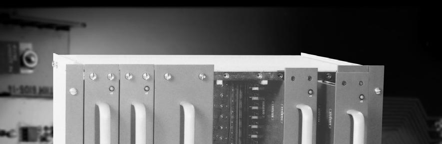
13 INTRODUCTION Model V/D Video Frame Front (812101) 7

14 Video Frame Back Panel (812101) Note The Model V/D shown here is a fully populated 128x128 video matrix. In some cases, this frame may be configured in smaller increments of 32. Please DO NOT MOVE INPUT BUFFERS WITHOUT CONSULTING THE SVS CUSTOMER SERVICE. The system you receive is customized for your size and is designed for future expansion when desired. 8
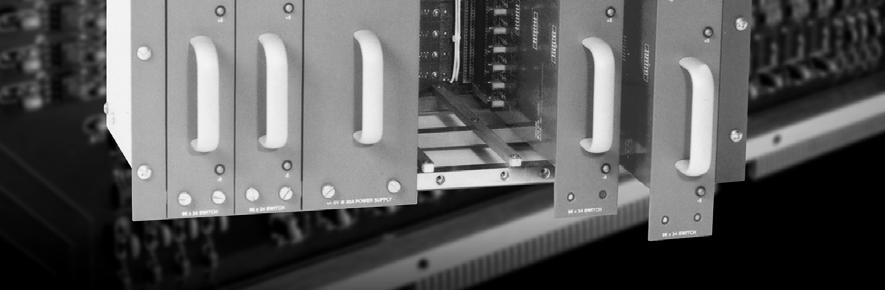
15 INTRODUCTION Model 9696V Video Frame Front (812100) 9
")
16 Video Frame Back Panel (812100) 10

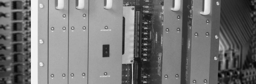
17 INTRODUCTION Model 6464V/D Video Frame Front Panel (812102) 11
")
18 Video Frame Back Panel (812102) 12

19 INTRODUCTION Model A Audio Frame Front Panel Audio Frame Back Panel 13
20 Model 6464A Audio Frame Front Panel Audio Frame Back Panel 14
21 INTRODUCTION Model E Audio Frame Front Panel Audio Frame Back Panel 15
22 Model 6464E Audio Frame Front Panel Audio Frame Back Panel 16


23 Chapter 2 Video Overview Analog Video Signal Path Overview The Yosemite Family of analog video routing switchers are based on conventional single stage crosspoint matrix design. The signal path consists of three elements or modules: 1. Input buffer 2. Crosspoint modules 3. Input / output sub-assemblies 17

24 Input Buffers Each input buffer consists of a small adapter on the rear of the frame that converts the 75 ohm analog video input into a buffered, very low impedance load (under 5 ohms). Each adapter module contains a 400 Mhz linear circuit. The signal is distributed via a PWA ( Printed Wiring Assembly, also known as a circuit board) motherboard to the crosspoint matrix portion of the router. The 64x64-frame assembly consists of two sections. Each of these sections has 32 input buffer assemblies and a motherboard which distributes the video signals. The 96x96 routing switcher consists of three sections of 32 inputs each; the 128x128 frame consists of four sections of 32 inputs each. All analog Yosemite Family video routing switchers including wide bandwidth systems use the same input buffer adapter. The obvious advantage to having each individual input buffer mounted externally is easy maintenance. Changing an individual input buffer does not require powering the system down, nor does it require unsafe internal repairs. Please consult SVS Customer Service before moving any of the input buffers. Oftentimes Yosemite routing switchers are ordered with future expansion in mind. For example, a 128x128 frame can be ordered and configured with only 64 inputs and 64 outputs, requiring only 2 of the aforementioned input buffer assemblies and motherboards. In these cases, the input buffers will be wired for the customized configuration, possibly changing the input number as indicated on the frame. Do not move any of the input buffers installed by the factory without contacting SVS Customer Service. This may disrupt system performance if wired incorrectly. 18
25 VIDEO OVERVIEW Crosspoint Modules The Yosemite Family analog video switcher uses the newest technology available for the crosspoint matrix. The crosspoint matrix is built using 250MHz high performance surface mount crosspoint arrays. The crosspoint modules in the Yosemite analog video routers are 32x32 switching sub-matrices. The 32x32 matrix consists of eight 16x8 250MHz crosspoint IC s. Likewise, to offer ultimate flexibility in the Yosemite line, the 96x96 analog video routing switcher uses only 6 of the crosspoint IC s to make a 32x24 switching sub-matrix. This results in very exceptional performance and high system density throughout the Yosemite series. 19


26 Input / Output Sub-assemblies Yosemite 6464V/D The 32x32/ 32x24 crosspoint modules are part of a larger plug-in sub-assembly. In the 64x64 system, two 32x32 crosspoint modules are combined with a 32-channel output assembly to constitute a 64x32 subunit. A complete 64x64 7RU system consists of two of these sub-assemblies. A 32x64 system would consist of 32 input buffers installed with only one of the two possible 32x32 crosspoint modules installed in each 64x32 assembly. The result would function as a 32x32 sub-assembly. Yosemite 9696V The 96x96 11RU frame has positions for four 96x24 matrix sub-assemblies. Each of these is built from up to three 32x24 crosspoint sub-assemblies. In this situation, eight of the outputs on each 32x32 module are not used. Yosemite V/D The 128x128 14RU frame has positions for four 128x32 matrix sub-assemblies. Each of these is built from up to four 32x32 crosspoint sub-assemblies. Interchangeable Assemblies Except for the output driver half of the output assembly and the power supply(ies), the other modules are interchangeable between 64x64, 96x96, and 128x128 systems. This includes the control processor module. 20

27 VIDEO OVERVIEW Digital Video Signal Path Overview The Yosemite Family of digital video routing switchers are based on the same aforementioned conventional single stage crosspoint matrix design. The signal path consists of four elements or modules: Input Buffer 1. Input buffer 2. Crosspoint modules 3. Input / output sub-assemblies The input module assembly for each input of a Yosemite digital video router contains an automatic adaptive cable equalizer and four differential, controlled-impedance, transmission line drivers. Each input buffer consists of a small adapter module on the rear of the frame that is a combination 15 through 600 Mbps adaptive cable equalizer and fan-out distribution amplifier. The adapter accepts SDI data rates and connects to the internal crosspoint sub-assemblies directly. The 64x64-frame assembly consists of two sections. Each of these sections has 32 input buffer assemblies and a motherboard which distributes the video signals. The 128x128 frame consists of four sections of 32 inputs each. All digital Yosemite Family video routing switchers use the same input buffer module. The obvious advantage to having each individual input buffer mounted externally is for easy maintenance. Changing an individual input buffer does not require powering the system down, nor does it require unsafe internal repairs. Please consult SVS Customer Service before moving any of the input buffers. Oftentimes Yosemite routing switchers are ordered with future expansion in mind. For example, a 128x128 frame can be ordered and configured with only 64 inputs and 64 outputs, requiring only 64 of the aforementioned input buffer assemblies and two motherboards. In these cases, the input buffers will be wired for the customized configuration, possibly changing the input number as indicated on the frame. Do not move any of the input buffers installed by the factory without contacting SVS Customer Service. This may disrupt system performance if wired incorrectly. Crosspoint modules The motherboard design used in Yosemite video routing switchers incorporates a number of unique design features. In the digital router, the motherboard provides a separate, very high-speed differential transmission line to each crosspoint module in the system. This avoids any need for additional internal distribution devices and allows all crosspoint IC s in the system to be end-of-line terminations. This means that there will be no high impedance internal stub connections that may cause reflections that often equates to jitter problems. 21
 64x33 1.5Gbps integrated circuit.")
28 As with the Yosemite analog routing switcher, we have based our digital video design on the most up-todate crosspoint technology. The basic switching device is a GaAs (Gallium Arnside) 64x33 1.5Gbps integrated circuit. 22
29 VIDEO OVERVIEW Input / Output sub-assemblies The 64x64 digital video router is comprised of two plug-in sub-assemblies. One half of each of these assemblies is a 64x33-crosspoint module. The 64x33 crosspoint module mates with a 33 channel output driver module to complete the sub-assembly. Because the basic crosspoint unit is a 64x33 module, the 96x96 frame is not suitable or cost-effective for digital video. The 128x128 frame has up to four plug-in sub-assemblies. Each of these is comprised of two 64x33 crosspoint modules and a 33 channel output driver. The output driver has thirty-three 2x1 switchers that select between the output of the two 64x33 crosspoint modules. Thirty-two of these 2x1s are comprised of ¼ of an 8x8 crosspoint IC configured as a 2x1 switch. Consequently, the 128x128 digital router signal path only passes through two cascaded crosspoints. The outputs of the 2x1 switches connect to a re-clocking circuit. The re-clocking circuit automatically switches to the correct data rate, which supports up to four data rates. The standard digital Yosemite 64x64 and 128x128 systems are shipped with re-clocking set to 143mbps, 177mbps, 270mbps, and 360mpbs. If another data rate is desired or if the re-clocker needs to be bypassed, contact Sierra video for additional information. 23

30 Additional Monitoring Outputs As stated in the above paragraphs, the 33 rd output on each sub-assembly is an additional output. The Yosemite 64x64 system is actually a 64x66 and the 128x128 is actually a 128x132. Each of the 33 rd outputs appears on the BNC connectors on the front of the output module assembly, rather than on the rear of the frame. The most common use of the 33 rd outputs is service monitoring. In the 64x64 system, the extra outputs are mapped to outputs 65 and 66. These extra outputs must be addressed on the control processor to function properly. For more 64x64 information and for 128x128 system functionality, please consult Sierra Video. Analog to Digital Upgrade Capability A key feature of Yosemite Family Routing Switchers allows the same frame to be used for analog or digital video routing. An analog router can be changed to a digital system by replacing the analog modules with digital modules. Because digital video requires more power, upgrading power supplies is also required. This permits a system to be upgraded in the field from an analog system to a digital system. Video / Audio Compatibility All of the Yosemite video frames mentioned above are compatible with both Yosemite audio frames and modules. Moreover, Yosemite can be interconnected to most other Sierra Video units, or RS-422 Port routing switcher. For more information, on combining systems to include analog, digital, mono audio, stereo audio, or any other format, please contact Sierra video. 24
31 Chapter 3 Audio Overview Introduction The Yosemite Series Audio routing switchers from Sierra Video are modular for those applications requiring worry-free performance and mission critical reliability. The advanced features and performance set it apart from the competition. These include: Modular configurations expandable by 32 input and/or 32 output increments Compact frame size 3RU (6464 frame) or 5RU ( frame). Hot-swappable I/O boards. Standard redundant power supplies. Full range of Sierra control hardware and software components, including remote control panels, and RS-232/422 serial control. Supported by all major third party control systems. Front-door access to hot-swappable I/O boards allows for field service or matrix reconfiguration. Serial control is standard in every model. The analog audio frames populate in increments of 32 on both the inputs and outputs, and come in two compact sizes: 3RU and 5RU. These frames can be configured to be either mono or stereo and are set at the factory. For example, the 3RU frame can be ordered to be either a 64x64 mono or 32x32 stereo audio router. When in the stereo mode, each channel is independently switchable. 25
32 Frame Configurations Yosemite Audio frames can be ordered in a mono or stereo mode. Configuration is done at the factory or can be changed in the field (see section on stereo mode operation). Mono Configurations A/E Frame 6464 A/E Frame 32x32 32x32 32x64 32x64 64x32 64x32 64x64 64x64 32x96 96x32 64x96 96x64 96x96 32x128 64x x64 96x x96 128x128 Stereo Configurations A/E Frame 6464 A/E Frame 16x16 16x16 16x32 16x32 32x16 32x16 32x32 32x32 16x48 48x16 32x48 48x32 48x48 16x64 32x64 64x32 48x64 64x48 64x64 26
33 AUDIO OVERVIEW Analog Audio Signal Path Overview The Yosemite Family audio routing switcher signal path consists of two modules: an input buffer, and a combination crosspoint module / output driver module. The same two modules are used for both frame sizes: 64x64 and 128x128. Input Buffers Each input buffer module has 32 identical circuits. Yosemite routers are designed to work in broadcast and production facilities, and are compatible with balanced interconnections. The buffers have multiple purposes: 1. Present a high impedance to the incoming signal 2. Remove unwanted common mode IE Hum signal 3. Convert the signal to the level and impedance needed by the switching matrix that follows The output of the input buffer circuits are connected to the switching matrix via the internal motherboard. Unlike their analog video counterparts, the input buffers are internally mounted. The 64x64 frame has positions for two 32-channel buffer modules; and the 128x128 frame has positions for four 32-channel buffer modules. 27

34 Crosspoint Sub-assembly Modules The analog audio crosspoint module used in the Yosemite Family is a 128x32 module. The switching integrated circuit (IC) is a HCMOS 16x8 array. Thirty-two of these switching IC s are arranged to form a 128x32 matrix. Each output bus from the switching matrix feeds a differential output. The output driver provides a symmetrical low impedance output signal. The 64x64 frame has positions for two 128x32 / 32-channel output driver modules; the 128x128 frame has positions for four 128x32 / 32-channel output driver modules. Grounding the negative side of the output drive adds +6dB of audio gain. 28

35 AUDIO OVERVIEW Digital Audio Signal Path Overview As with analog audio systems described above, the digital audio Yosemite routing switchers use digital modules with the same form factor. Our digital audio frames are available with both asynchronous and synchronous options. These audio AES/EBU compatible routers use high-frequency digital 110 ohm balanced line receivers. They can also be ordered to support S/PDIF single-ended signals with an input/output impedance of 75 ohm. Input buffers The basic digital audio input buffer module has thirty-two balanced 110 ohm AES/EBU audio line receiver circuits that in turn connect their outputs via the motherboard to the crosspoint modules. Synchronous digital audio input buffers can replace the non-processing, asynchronous, version in blocks of 32 inputs as desired. Asynchronous digital audio When the routing switcher is used as a preselector to production devices that have their own synchronizing systems, there are generally no conflicts. This is understandably called asynchronous audio. In applications where asynchronous audio is sufficient, our AES 110 ohm module provides costeffective, high performance routing of any data rate input at a signal rate frequency range of 100 KHz to 8 MHz. 29
36 Digital Audio Output Accessories 75 ohm Unbalanced Digital Audio By using BNC adapter panels, each of the 110 ohm balanced inputs is converted to 75 ohm unbalanced 1 V P-P nominal input level. The BNC conversion / adapter panel option for the outputs converts each output to BNC connectors with 75 ohm source impedance and nominal 1 V P-P output level. The adapter panels require more space than the routing switcher. They are separate rack mount panels which interconnect to the 25 in D connectors with short cables that we provide with the adapter panels. 110 ohm Balanced Digital Audio All inputs are internally terminated with 110 ohms in the Yosemite digital audio routing switchers. Likewise, all outputs are source-terminated with 110 ohms (55 ohms per line). Video / Audio Compatibility All of the Yosemite audio frames mentioned above are compatible with all three Yosemite video frames. Moreover, Yosemite can be interconnected to any Sierra model, providing the other unit has a J1 connector, or RS-422 Port routing switchers. For more information, on combining systems to include analog, digital, high definition, stereo audio, or any other format, please contact Sierra Video. 30

37 Chapter 4 Installation Introduction Installation procedures are similar for all frames covered under this manual. However, differences between video frame and audio frame installation exist. Exceptions, if any, have been noted in each of the following paragraphs. Video Frame Rack Mounting Carefully inspect the frame to ensure that there has been no shipping damage. Make sure all modules are seated completely in the frame. Each of the Yosemite video routing switchers described in this manual can be rack mounted in a standard 19" (RU) EIA rack assembly and includes integrated rack "ears" at each side of the front of the frames. 31

38 Vertical Spacing Requirements It is important to provide unrestricted vertical cooling space for all three Yosemite analog and digital video routing switcher frames. Cooling of the Yosemite Family video switchers is by vertical convection cooling. Some models have supplemental cooling fans built into the power supply sub-assemblies. However, the power supply fans are only used for the power supplies and are not intended to promote airflow to the crosspoint and output module assemblies. The digital video routers consume approximately twice the power of similar-sized analog routing switchers. Supplemental cooling fans are recommended in situations where there may not be good control of ambient air temperature or where there is restricted airflow. When no cooling fans are used at least 1RU of blank space should be left between video frames. Component video (YC, RGB, RGB+S, RGB+H+V) and 128x256 video frames can be stacked without immediate cooling space if a common forced air fan assembly is used at the top and/or bottom of the frame combination. To rack mount a Yosemite video routing switcher, simply place the unit's rack ears against the rails of the rack, and insert proper rack screws through each of the holes in the rack ears. Use all screw holes in the mounting ears when mounting the frame in the equipment rack to insure proper support for the frame. AC Power Connections The power supplies in the video routing switcher frames are universal AC inputs. Voltage selection is not necessary because the power supply senses the correct AC input automatically. The power supply units for the Yosemite video routers are internal plug-in sub-assemblies. If you only ordered one power supply with your initial system, you can add a second supply in the future. When redundant power supplies are used, two AC power cords should be connected to separate AC lines or circuit breakers to maximize the benefits of the having two power supplies. Turn on power to the frame ONLY AFTER all video and control connections have been completed as described below. 32
39 INSTALLATION Before Connecting To Video Devices Yosemite video routing switchers have a unique video input design. At the rear of frame, each video input buffer / processing circuit is built in a separate adapter See Video Overview: Input Buffers for more information. One end of the adapter is a BNC connector. The other end of the adapter is a 15 pin D miniature connector. When less than the maximum number of inputs are ordered, for example a 64x64 analog video router in a 128x128 frame, some input buffers will not be present. If you ordered the frame in smaller increments, the Input Numbers labeled on the frame may differ. Please DO NOT MOVE INPUT BUFFERS WITHOUT CONSULTING SVS CUSTOMER SERVICE. It is important that only Sierra video input buffer modules be used to connect the 15 pin D connector(s). Because the analog and digital Yosemite Family video routing switchers use different internal DC voltages, it is very important that you use ONLY an analog type adapter on analog routers and that you use ONLY the digital adapter on digital systems. IMPORTANT NOTE: When less than the maximum number of inputs are ordered, for example a 64x64 analog video router in a 128x128 frame, some input buffers will not be present. If this is the case, the Input Numbers labeled on the frame may differ. Please DO NOT MOVE INPUT BUFFERS WITHOUT CONSULTING SVS CUSTOMER SERVICE. Connecting To Video Devices Video sources and output devices (such as monitors, or recorders) may be connected to the routing switchers through the BNC type connectors located on the back of the unit. Keep in mind that the output signal format will be that of the input signal format. All signal connections that use more than one cable interconnecting between devices should be of equal timing length (example: cables between a camera and the switcher should have the same time delay). When making cable connections to the input adapters, leave enough service loop in each coax cable to allow for the removal and replacement of the adapter modules in the event that service is needed. It may be easier to remove and reinstall adapter modules with the coax cable attached, instead of removing the adapter from the cable. All inputs are terminated in 75 ohms and all outputs have a source impedance of 75 ohms. Unused inputs and outputs can be left with no connection. No external termination resistor is needed. Yosemite Family video routing switchers have two output BNC s per destination. This is a particularly important feature in the installation of the digital video router. The second BNC will save space and prevent performance degradation problems associated with external digital distribution amplifiers but at a lower cost. Unused video outputs can be left with no connection. 33

40 Vertical Interval Switching Sync Input The sync input is used to generate vertical interval switching. If no sync is available, the routing switcher will switch at a random point rather than in the vertical interval. There are two BNC connectors labeled sync located above the power supply mains and RS-485 control panel connectors on the left of the video frame. These are looping inputs. Connect either composite sync or video with sync to either sync input BNC. If you desire, use the second BNC to loop the signal to another device. If you do not use a loop, terminate the second BNC with a 75-ohm termination. The Vertical Switching Interval is also discussed in the Communication Protocol Section in this manual. 34
41 INSTALLATION Audio Frame Mounting Carefully inspect the frame to ensure that there has been no shipping damage. Make sure all modules are seated completely in the frame. Each of the Yosemite audio routing switchers described in this manual can be rack mounted in a standard 19" (RU) EIA rack assembly and includes rack "ears" at the ends of the front of the frames. Ventilation Yosemite Family audio frames use horizontal airflow and may be mounted adjacent to other equipment. Do not obstruct the cooling holes on the left side of the frame. Do not obstruct the fan discharge on the right side of the frame. If you are mounting an audio frame with a Yosemite video frame, be sure to allow at least 1RU of space between the two frames and please follow the ventilation spacing requirements as indicated in the video installation section of this manual. AC Power Connection The power supplies in the audio routing switcher frames are universal AC inputs. Voltage selection is not necessary because the power supply senses the correct AC input automatically. When redundant power supplies are used, two AC power cords should be connected to separate AC lines or circuit breakers to maximize the benefits of the having two power supplies. The real purpose of the dual supply is to protect the router from loss of power at it source. Turn on power to the frame ONLY AFTER all audio and control connections have been completed as described below Note: The redundant supply option can not be added in the field: it must be ordered as part of the original system or sent back to the factory for installation. 35

 side and use the positive (+) side for both inputs and outputs.")
42 Connecting To Audio Devices Mono Analog Audio Audio sources and destination devices (such as amplifiers or recorders) may be connected to the switchers via a 5-pin latching, removable, terminal block style connectors located at the back of the switchers. Balanced/Unbalanced Analog Audio Connections All audio sources from the routing switcher are balanced audio. Connect the balanced audio to the balanced input of your destination device(s). To convert balanced to unbalanced audio signals, ground the negative (-) side and use the positive (+) side for both inputs and outputs. Grounding the negative side of the output drive adds +6dB of audio gain. The audio pin outs for balanced and unbalanced audio are described in the tables below: 36
43 INSTALLATION Stereo Analog Audio Yosemite Audio frames can be ordered in a mono or stereo mode and are pre-configured at the factory. Input and output connections differ when the unit is in the stereo mode. In the mono mode connectors are wired as silk screened on the rear of the router. However, when ordered in the stereo mode, the input or output is wired as indicated below; Stereo Audio Wiring Connector # Connector # Connector # Connector # I/O # Left Right I/O # Left Right I/O # Left Right I/O # Left Right
.")
44 Balanced Digital Audio Yosemite digital audio routers use 25-pin D connectors for input and output connection. All inputs are internally terminated with 110 ohms in the digital audio routing switchers. Likewise, all outputs are source-terminated with 110 ohms (55 ohms per line). When balanced digital audio is ordered, Sierra Video supplies a removable screw terminal adapter. Use of the adapter is optional. Each adapter panel connects to 4 of the 25-pin D connectors. This connects a total of 32 inputs or outputs. The 25-pin D connectors each support a group of 4 inputs or outputs and the screw terminals are in groups of 4 containing 2 inputs or outputs each. Example: If an adapter panel is connected to the top row of 25-pin D connectors on the back of the frame, the screw terminals will be configured as below; Rear of Frame Inputs Inputs Inputs 9-16 Inputs
45 INSTALLATION Use of the screw terminal adaptable is optional. If it is preferred to wire directly to the 26-pin D connectors using a male 25-pin D connector, the pinout connections are as follows; Inputs & Outputs 1-32 Audio Pin Connections I/Os 1-32 Pin # Pin #1 8 (+) 16 (+) 24 (+) 32 (+) Pin #14 8 (-) 16 (-) 24 (-) 32 (-) Pin #2 Ground Ground Ground Ground Ground Ground Ground Ground Pin #15 7 (+) 15 (+) 23 (+) 31 (+) Pin #3 7 (-) 15 (-) 23 (-) 31 (-) Pin #16 Ground Ground Ground Ground Ground Ground Ground Ground Pin #4 6 (+) 14 (+) 22 (+) 30 (+) Pin#17 6 (-) 14 (-) 22 (-) 30 (-) Pin #5 Ground Ground Ground Ground Ground Ground Ground Ground Pin #18 5 (+) 13 (+) 21 (+) 29 (+) Pin #6 5 (-) 13 (-) 21 (-) 29 (-) Pin #19 Ground Ground Ground Ground Ground Ground Ground Ground Pin #7 Ground Ground Ground Ground Ground Ground Ground Ground Pin #20 Ground Ground Ground Ground Ground Ground Ground Ground Pin #8 4 (+) 12 (+) 20 (+) 28 (+) Pin #21 4 (-) 12 (-) 20 (-) 28 (-) Pin #9 Ground Ground Ground Ground Ground Ground Ground Ground Pin #22 3 (+) 11 (+) 19 (+) 27 (+) Pin #10 3 (-) 11 (-) 19 (-) 27 (-) Pin #23 Ground Ground Ground Ground Ground Ground Ground Ground Pin #11 2 (+) 10 (+) 18 (+) 26 (+) Pin #24 2 (-) 10 (-) 18 (-) 26 (-) Pin #12 Ground Ground Ground Ground Ground Ground Ground Ground Pin #25 1 (+) 9 (+) 17 (+) 25 (+) Pin #13 1 (-) 9 (-) 17 (-) 25 (-) 39
46 Inputs & Outputs Audio Pin Connections I/Os Pin # Pin #1 40 (+) 48 (+) 56 (+) 64 (+) Pin #14 40 (-) 48 (-) 56 (-) 64 (-) Pin #2 Ground Ground Ground Ground Ground Ground Ground Ground Pin #15 39 (+) 47 (+) 55 (+) 63 (+) Pin #3 39 (-) 47 (-) 55 (-) 63 (-) Pin #16 Ground Ground Ground Ground Ground Ground Ground Ground Pin #4 38 (+) 46 (+) 54 (+) 62 (+) Pin#17 38 (-) 46 (-) 54 (-) 62 (-) Pin #5 Ground Ground Ground Ground Ground Ground Ground Ground Pin #18 37 (+) 45 (+) 53 (+) 61 (+) Pin #6 37 (-) 45 (-) 53 (-) 61 (-) Pin #19 Ground Ground Ground Ground Ground Ground Ground Ground Pin #7 Ground Ground Ground Ground Ground Ground Ground Ground Pin #20 Ground Ground Ground Ground Ground Ground Ground Ground Pin #8 36 (+) 44 (+) 52 (+) 60 (+) Pin #21 36 (-) 44 (-) 52 (-) 60 (-) Pin #9 Ground Ground Ground Ground Ground Ground Ground Ground Pin #22 35 (+) 43 (+) 51 (+) 59 (+) Pin #10 35 (-) 43 (-) 51 (-) 59 (-) Pin #23 Ground Ground Ground Ground Ground Ground Ground Ground Pin #11 34 (+) 42 (+) 50 (+) 58 (+) Pin #24 34 (-) 42 (-) 50 (-) 58 (-) Pin #12 Ground Ground Ground Ground Ground Ground Ground Ground Pin #25 33 (+) 41 (+) 49 (+) 57 (+) Pin #13 33 (-) 41 (-) 49 (-) 57 (-) 40
47 INSTALLATION Inputs & Outputs Audio Pin Connections I/Os Pin # Pin #1 72 (+) 80 (+) 88 (+) 96 (+) Pin #14 72 (-) 80 (-) 88 (-) 96 (-) Pin #2 Ground Ground Ground Ground Ground Ground Ground Ground Pin #15 71 (+) 79 (+) 87 (+) 95 (+) Pin #3 71 (-) 79 (-) 87 (-) 95 (-) Pin #16 Ground Ground Ground Ground Ground Ground Ground Ground Pin #4 70 (+) 78 (+) 86 (+) 94 (+) Pin#17 70 (-) 78 (-) 86 (-) 94 (-) Pin #5 Ground Ground Ground Ground Ground Ground Ground Ground Pin #18 69 (+) 77 (+) 85 (+) 93 (+) Pin #6 69 (-) 77 (-) 85 (-) 93 (-) Pin #19 Ground Ground Ground Ground Ground Ground Ground Ground Pin #7 Ground Ground Ground Ground Ground Ground Ground Ground Pin #20 Ground Ground Ground Ground Ground Ground Ground Ground Pin #8 68 (+) 76 (+) 84 (+) 92 (+) Pin #21 68 (-) 76 (-) 84 (-) 92 (-) Pin #9 Ground Ground Ground Ground Ground Ground Ground Ground Pin #22 67 (+) 75 (+) 83 (+) 91 (+) Pin #10 67 (-) 75 (-) 83 (-) 91 (-) Pin #23 Ground Ground Ground Ground Ground Ground Ground Ground Pin #11 66 (+) 74 (+) 82 (+) 90 (+) Pin #24 66 (-) 74 (-) 82 (-) 90 (-) Pin #12 Ground Ground Ground Ground Ground Ground Ground Ground Pin #25 65 (+) 73 (+) 81 (+) 89 (+) Pin #13 65 (-) 73 (-) 81 (-) 89 (-) 41
48 Inputs & Outputs Audio Pin Connections I/Os Pin # Pin #1 104 (+) 112 (+) 120 (+) 128 (+) Pin # (-) 112 (-) 120 (-) 128 (-) Pin #2 Ground Ground Ground Ground Ground Ground Ground Ground Pin # (+) 111 (+) 119 (+) 127 (+) Pin #3 103 (-) 111 (-1) 119 (-) 127 (-) Pin #16 Ground Ground Ground Ground Ground Ground Ground Ground Pin #4 102 (+) 110 (+) 118 (+) 126 (+) Pin# (-) 110 (-) 118 (-) 126 (-) Pin #5 Ground Ground Ground Ground Ground Ground Ground Ground Pin # (+) 109 (+) 117 (+) 125 (+) Pin #6 101 (-) 109 (-) 117 (-) 125 (-) Pin #19 Ground Ground Ground Ground Ground Ground Ground Ground Pin #7 Ground Ground Ground Ground Ground Ground Ground Ground Pin #20 Ground Ground Ground Ground Ground Ground Ground Ground Pin #8 100 (+) 108 (+) 116 (+) 124 (+) Pin # (-) 108 (-) 116 (-) 124 (-) Pin #9 Ground Ground Ground Ground Ground Ground Ground Ground Pin #22 99 (+) 107 (+) 115 (+) 123 (+) Pin #10 99 (-) 107 (-) 115 (-) 123 (-) Pin #23 Ground Ground Ground Ground Ground Ground Ground Ground Pin #11 98 (+) 106 (+) 114 (+) 122 (+) Pin #24 98 (-) 106 (-) 114 (-) 122 (-) Pin #12 Ground Ground Ground Ground Ground Ground Ground Ground Pin #25 97 (+) 105 (+) 113 (+) 121 (+) Pin #13 97 (-) 105 (-) 113 (-) 121 (-) 42
49 INSTALLATION Unbalanced Digital Audio Since all audio sources and destinations in the routing switcher are balanced, Sierra Video supplies BNC adapter panels when you order unbalanced digital audio. By using BNC adapter panels, each of the 110 ohm balanced inputs is converted to 75 ohm unbalanced 1 V P-P nominal input level. The BNC conversion / adapter panel option for the outputs converts each output to BNC connectors with 75 ohm source impedance and nominal 1 V P-P output level. The adapter panels require more space than the routing switcher. They are separate rack mount panels which interconnect to the 25 in D connectors with short cables that we provide with the adapter panels. Each panel accommodates 4 of the 25-pin D connectors. Input BNC adapter panels are active and come with an external power supply. Output BNC adapter panels are passive and do not require power to operate. Unbalanced Audio Pin Out Example Pin # Pin #1 8 (+) 16 (+) 24 (+) 32 (+) Pin #14 Ground Ground Ground Ground Ground Ground Ground Ground Pin #2 Ground Ground Ground Ground Ground Ground Ground Ground 43
50 Video Plus Audio Frame Combinations Multiple video frames are frequently combined to form multi-level systems. The Yosemite Family can accommodate up to 8 separate control levels. At each of these levels there can be more than one channel of physical routing switchers. Frequently, component video (YC, RGB, etc.) will share the same control level. The same may be true of multiple analog audio channels. When multiple frames, audio and/or video, are combined into the same control system, all of the frames must be installed so that the high-speed control interconnect system is limited in length. The total length should not exceed 25 feet (7.6m). Multiple Yosemite Levels Under One Processor When a video frame (V or D) is combined with an audio frame (A or AA), a VA or VAA system is created. In these situations, we test the entire system as a unit at our factory. The entire system will only use one control processor module. The master frame is whichever frame contains the control. Sync, Host, Terminal and RS-485 connections are only made to the master frame. These connectors on the other frames should have no connection made to them. On the rear of each frame is a 25 pin D connector labeled J1. This connector is used to tie all frames in the system connector. When only two frames are combined, this cable will consist of a cable that is 1 meter long with a 25 pin male connector on each end. When three or more frames are combined, a ribbon cable with crimped 25 pin D connectors is used to tie the frame-to-frame J1 connectors. 44
51 INSTALLATION Default Yosemite Settings Before Sierra video ships a Yosemite, the routing switcher system is set with critical initial settings, unless otherwise specified at the time of order. These settings allow the user to install the system and have it quickly operational. Basic Size The number of sources, destinations, levels, and physical layers are the first items to be programmed. The factory configuration sets the number of sources equal to the number of inputs of that layer that has the most inputs. Likewise, the outputs are configured similarly. This process sets the number of layers and levels the same, equal to the number of physical crosspoint layers in the routing switcher (except in rare instances where two layers are combined to create a larger system). The configuration will vary with the software version. The Router Control Software allows a one-to-one correspondence between levels and physical layers with the number of levels equal to the number of layers. Beginning with version 5.02, the software allows multiple physical layers to be mapped on the same router level. However in most systems this is not the default. Settings Based on Software Version On routing switchers running software prior to 5.01, the sizes are set using the DIP switches on the control processor board. Systems running 5.01 must set the number of sources and destinations using Terminal Protocol and entering the control/w command while the number of layers is still set by the DIP Switches. Systems running 5.02 or later must set all four of these values (number of sources, destinations, levels, and layers) using the Sierra Video TyLinx Pro program or the Terminal Protocol control/w command (Hyper-term). Physical Size The number of inputs and outputs for each individual layer are assigned. The physical size, the number of the level which the layer is assigned, the offset of the input and output numbers of each layer within its level, the type of hardware mapping table to be used with each layer, the type of signal routed by each layer, and the presence or absence of hole in the input and output space on each layer are all set to configuration default. Holes can occur when a routing switcher is ordered with a partially-stuffed frame that can be expanded later to give additional inputs/ and/or outputs. The factory configuration places each layer on a separate level (except in those rare instances where two layers are combined to create a larger router), and assigns an offset of 0 for the input and output numbers. Field Delay The filed delay is the amount of time between the host command receiving! until the crosspoint is changed. The factory default is set to the minimum allowed delay. See the chapter on protocol to change the field delay. Control Panels Each control panel is set to a unique ID between 0 and 63. This is done at the control panels, not via software. Refer to your control panel User s Manual to set panel IDs. Control panel settings can be applied using the TyLinx Pro software. (See the TyLinx Pro manual for details). 45
52 Mapping Virtual & Physical Tables Virtual-to-physical mapping tables, used in software version and later, are configured for one-to-one mapping (e.g. source 1 is mapped to physical input 1) on all levels. An exception is made in the case of partially-stuffed routing switchers with holes. In these routers, the mapping is set to skip over the holes. This creates a discrepancy in the mapped input/outputs and the silk screened numbers on the rear of the frame. For example, if outputs 1-8 and existed on a router level, but outputs 9-32 did not exist (i.e. they area hole ), then mapping would be set to map virtual destination 9 to physical output 33, etc. An exception also occurs for the case of routing switchers with one or more levels that are smaller than the basic router size. In these cases, the mapping tables are set to map nothing to sources and destinations beyond the basic size of any given level. Salvo Table & Level Names Initially, the salvo table is empty. Level names are initialized to LVL 1, LVL 2 etc. Source names are initialized to SRC 1, SRC 2, etc. Destination names are initialized to DST 1, DST 2, etc. The routing switcher name is initialized to SVS ROUTER. Level names, salvos, and input/output names can be applied using the TyLinx Pro software. (See the TyLinx Pro manual for details). Administration Yosemite routing switchers use password administration to ensure security to your system. The Administrator password is set to 0, meaning no password (on software versions 5.01 and later). Yosemite DIP Switches Two types of control processors can be used to control Yosemite routing switchers. The Sierra video module is the most popular in the Yosemite line. This control processor is installed in a video frame and can control the routers interconnected to the video frame. If Yosemite Family video frames are not ordered in a system, a Sierra video Tahoe controller module is installed in one of the audio frames. All Yosemite audio frames have a module position prewired for a processor. More information on these two processor boards can be found in the following two chapters: Processors, and Processors. The and control processor boards have arrays of small switches called DIP Switches that are used to set some of the basic routing switcher configuration parameters. The two processor boards have different DIP Switch settings. SVS sets the DIP Switches to a default mode depending on the configuration at time of order. Please check the settings of each DIP Switch before powering on the system and make any necessary settings changes. The size of a routing switcher is limited by the amount of non-volatile memory present on the processor board. With full memory, the largest size, 256x256x8, can be reached. With smaller memory configurations, the maximum size limited to smaller values. Your Yosemite switcher has been configured at the factory for the settings you are most likely to need. However, if you want to configure the switcher differently, you can do so by the setting the switches located on the processor board ( or shown below). Dip Switches and their action are given in the tables that follow. Note: DIP Switch settings sometimes vary according to the version of software being run in the processor board. **The software version installed the processor is labeled on U14 and U24 of the processor module. 46

53 INSTALLATION Control Processor DIP Switches S1 S2 S3 S Control Processor Board S1 S Control Processor Board Note: Changing any Dip Switch causes an automatic reset after a few seconds DIP Switch settings sometimes vary according to the version of software being run in the processor board. **The software version installed the processor is labeled on U14 and U24 of the processor module. 47
54 Dip Switch Activation Yosemite DIP Switch devices have eight numerically marked switches. DIP Switch devices are labeled as S1, S2 or Switch 1, Switch 2. To activate a function or feature, locate the DIP Switch that controls that action in the tables below. Move the DIP Switch lever to the ON or OFF position specified in the table. For most cases, the silk-screened numbers on the device denote OFF, differing from the opposite silkscreened ON DIP Switch S1 & S2 Settings (Versions 8.05 or Older) Dip Switch Note: Action S1 (closest to edge) 1 Preferred CPU select: OFF = standby CPU ON = master CPU (dual processor systems only) 2 Redundant CPU processor enable: OFF = only one processor ON = redundant processors 3 Host protocol send X commands: OFF = initially OFF ON = initially ON* 4 For router status, send: OFF = an X command for each level * ON = mix Y, X, or V, use shortest 5 Force crosspoint initialization: OFF = restore previous xpts* ON = set xpts to 1-1, 2-2, 3-3 etc. S2 (second from edge) Port 2 protocol: OFF = Host / Terminal protocol* ON = Barco RCDS protocol Host protocol XON / XOFF send: OFF = don t send / disabled ON = send XON / XOFF / enabled* Port 2 parity: OFF = parity disabled* ON = parity enabled Port 2 parity type: OFF = even ON = odd Port 2 word length: OFF = 7 data bits On = 8 data bits* 6 Switch currently unused Port 2 type: OFF = RS-232* ON = RS Software download and update: OFF = normal operation* ON = download new software 8 Initialize non-volatile memory: OFF = normal operation* ON = clear all settings * = Factory default setting Port 2 speed with Host protocol: 1.2K baud 8 = off, 7 = off 9.6 K baud 8 = off, 7 = on* 38.4K baud 8 = on, 7 = off 115.2K baud 8 = on, 7 = on Or Port 2 speed with Rcds protocol: 1.2K baud 8 = off, 7 = off 9.6K baud 8 = off, 7 = on* 19.2K baud 8 = on, 7 = off 57.6K baud 8 = on, 7 = on Changing any Dip Switch causes an automatic reset after a few seconds DIP Switch settings sometimes vary according to the version of software being run in the processor board. **The software version installed the processor is labeled on U14 and U24 of the processor module. 48
55 INSTALLATION DIP Switch S3 & S4 Settings (Versions 8.05 or Older) Dip Switch Action S3 (third from edge) S4 (closest to LEDs) 1 Switches 2 & 1 currently unused. Switches 1-8 on S4 currently unused: board crystal frequency: OFF = MHz ON = MHz* 4 Port 1 initial protocol: OFF = Terminal* ON = Host 5 Port 2 initial protocol: OFF = Terminal ON = Host* 6 Port 1 type: OFF = RS-232* ON = RS Port 1 speed: OFF = 9.6K baud* ON = 19.2K baud 8 Panel RS-485 port speed: OFF = 9.6K baud ON = 31.25K baud* * = Factory default setting 49
56 DIP Switch S1 & S2 Settings (Versions 9.01 or Newer) Dip Switch Note: Action S1 (closest to edge) 1 Preferred CPU select: OFF = standby CPU ON = master CPU (dual processor systems only) 2 Redundant CPU processor enable: OFF = only one processor S2 (second from edge) Port 2 protocol: OFF = Host / Terminal protocol* ON = Barco RCDS protocol Port #2 XON / XOFF Both ways: OFF = Disabled ON = redundant processors ON = Enabled* 3 Unused Port 2 parity: OFF = parity disabled* ON = parity enabled 4 Unused Port 2 parity type: OFF = even* ON = odd 5 Force crosspoint initialization: OFF = restore previous xpts* ON = set xpts to 1-1, 2-2, 3-3 etc. 6 Port #2 configuration: OFF = Port #2 config non-volatile ON = Port #2 config always by S2 * 7 Software download and update: OFF = normal operation* ON = download new software 8 Initialize non-volatile memory: OFF = normal operation* ON = clear all settings * = Factory default setting S3 and S4 are unused Port 2 word length: OFF = 7 data bits On = 8 data bits* Port 2 type: OFF = RS-232* ON = RS-422 Port 2 speed with Host protocol: 1.2K baud 8 = off, 7 = off 9.6 K baud 8 = off, 7 = on* 38.4K baud 8 = on, 7 = off 115.2K baud 8 = on, 7 = on Or Port 2 speed with Rcds protocol: 1.2K baud 8 = off, 7 = off 9.6K baud 8 = off, 7 = on* 19.2K baud 8 = on, 7 = off 57.6K baud 8 = on, 7 = on Changing any Dip Switch causes an automatic reset after a few seconds DIP Switch settings sometimes vary according to the version of software being run in the processor board. **The software version installed the processor is labeled on U14 and U24 of the processor module. If S1-6 is off, S2 settings are only used when non-volatile memory is initialized. If S1-6 is on, S2 settings are used each time the router powers up. In either case, the port settings may be changed in software while the router is running. Whenever S2 settings are used to set port #2, the port will also be set to use the standard SVS host/terminal protocol. XOn/XOff flow control is forced on in both directions for both host and terminal protocols, and is forced off in both directions for panel and RCDS protocols on all ports regardless of switch settings or port configuration. 8 data bits and no parity is forced on all ports for panel and RCDS protocols regardless of switch settings or port configuration. All ports always use 1 stop bit. 50
57 INSTALLATION S1 and S2 DIP Switch Settings Dip Switch Action S1 1 Terminal port speed: OFF = 9.6K baud* On = 19.2K baud 2 Terminal port initial protocol: OFF = Terminal protocol* ON = Host protocol 3 Host port speed: 4 OFF 3 OFF 1.2K baud 4 4 OFF 3 ON 9.6K baud* 4 ON 3 OFF 38.4K baud 4 ON 3 ON 111.2K baud 5 Host port data bits: OFF = 7 data bits ON = 8 data bits* 6 Host port parity: OFF = even* ON = odd 7 Host port parity enable: OFF = parity disabled* ON = parity enabled 8 Host port XON/XOFF send: OFF = disabled ON = enabled* S2 * = Factory default setting Host protocol send X (or Y, V) command: OFF = initially disabled (U1 enables) ON = initially enabled (U0 disables)* Panel RS-485 port speed OFF = 9.6K baud ON = 31.25K baud* Software download and update OFF = normal operation ON = download new software Host port initial protocol: OFF = Terminal protocol ON = Host protocol* For router status, send: OFF = an X cmd for each level * ON = mix Y, X, or V commands (use shortest) Force crosspoint initialization: OFF = restore previous crosspoints* ON = set initial xpts to 1-2, 2-2, etc. Force router re-initialization to factory configuration settings: 0FF = normal* ON = reinitialize 51
58
59 Chapter 5 Operation Control System Overview The Yosemite Family s three port control system incorporates many powerful features, while retaining control compatibility with many leading third party control systems and with most earlier generation SV routing switchers. The control systems uses an intuitive interface for routing switcher control and configuration, pass wording, salvo setup, multiple input/output configuration and name configuration. Windows based, client/server software is IP addressable and supports event timing and bitmap icons. Up to 64 control panels can be linked at any one time, daisy-chained on a single RS-485 network. A variety of control panel styles are available including single-bus, X-Y, simple keypad, color LCD multi-bus, and fully programmable rotary panels. Connectors associated with the system s internal control computer are located on the rear of the Yosemite routing switcher frames. When systems are ordered with more than one frame, only one frame will have a control computer module installed. The following pertains to the frame that contains the master control CPU processor, either or Additional frames will need to be installed and connected to the master processor as described in the installation section above. Note: The control system and its software may vary slightly between the and CPU processor. Consult Sierra Video if you have questions. Speed The Yosemite control processors have the ability to perform several dozen switches within a single interval. The circuit used for the Yosemite Family controller is 2 to 4 times faster than the controller used in the Tahoe / Yosemite Audio Families, while being based on the same micro processor: the Motorola MC Serial Control Ports The internal control CPU processor has three serial ports for Terminal, Host, and RS-485 control panel protocol. These three serial ports are used for overall routing switcher system personalities, local or networked PC computer control, and control panel network operation. Terminal Protocol is a humanreadable protocol while Host Protocol is a machine-friendly protocol. The three serial ports are shipped with a factory default as described below. Altering DIP Switch settings may interrupt the default port settings. 53
. Port 1 is shipped with Terminal protocol mode set as default.")
60 Port 1 (Terminal Port) Yosemite routing switchers have two 9-pin RS232 connectors that allow you to control the switcher using a standard personal computer or other external devices (such as Creston or AMX). Port 1 is shipped with Terminal protocol mode set as default. A 9-pin connector labeled RS232/422 Port 1, located above the sync input reference mains, is used for a simple terminal (V=T100 emulation capability). Port 1 in Terminal mode has these main functions: Serves as overall system controller Sets up and view the personality of the entire system (size, level control, change names, mapping, etc.) These functions are stored in non-volatile memory on the master processor so that a terminal is not required unless it is necessary to change a setup. Connections to the 9-pin are shown in the table below. Transmit and Receive refer to what is inside the system. Connect to the opposite function at your end. 54
61 OPERATION Port 2 (Host Port) Port 2 is shipped with Host protocol mode set as default. A 9-pin connector labeled RS232/422 Port 2, located above the sync input reference mains, follows an ASCII protocol control. Port 2 in Terminal mode has these main functions: Serves as protocol for PC computer connection (TyLinx Pro) Serves as protocol for third-party device These functions are stored in non-volatile memory on the master processor so that a terminal is not required unless it is necessary to change a setup. Connections to the 9-pin are shown in the table below. Transmit and Receive refer to what is inside the SVS system. Connect to the opposite function at your end. 9 Pin Serial Connections Host & Terminal Port Installation Pin RS-232 RS Ground Ground 2 Transmit Transmit (-) 3 Receive Receive (+) 4 Not used Not used 5 Not Used Not used 6 Not used Not used 7 Not used Transmit (+) 8 Not Used Receive (-) 9 Ground Ground Serial Adapter Connections for Older Systems To configure a routing switcher, a standard computer terminal, or more likely, a PC running a terminal emulator program such as HyperTerminal, HyperAccess, or Procomm, must be connected to a router serial port that is running Terminal Protocol. SVS sells interface cables, or you can make your own. If you choose to make your own, take note of these points: The pin out of the 9-pin D connector on the frame is not the same as the pin out of the 9-pin connector or a typical PC Both Terminal & Host Protocols use software flow control, so you do not connect signals like DTR, RTS, SDR, CTS, or RI. Only three wires are needed: transmit data, receive data, and signal ground. Serial Control Cable Wiring Diagram Factory default settings: 9600 Baud, 8 Data Bits, No Parity, 1 Stop Bit. 55
62 Changing Ports 1 & 2 Between Host & Terminal To change a port setup, send special character sequences to the port (or type this sequence in at a terminal). See DIP SWITCHES for more information. To switch Port 1 to Host protocol: OR 1. Turn off the switcher and remove the serial control module (504001, ) 2. Turn off Dip Switch 5 on the s S2; turn on Dip Switch 4 on the s S3. 3. Reinstall the serial board and turn power back on. The serial port now uses the Host protocol. 4. Connect a terminal to the serial port using the serial adaptor and send the following command: **HOST1!! The port now uses the Host protocol. 5. To restore back to the Terminal port, send the following command: **HOST0!! 6. You are now back to the Terminal protocol. NOTE: By changing the Dip Switch, the protocol comes up either Host or Terminal depending upon the switch. On is for Host, Off is for terminal. 56

63 OPERATION Port 3 (RS-485 Control Panels) Yosemite Family video routing switcher frames have four male 3-pin connectors labeled RS-485 Control Panels on the rear. Yosemite Family audio frames have just two male 3-pin connectors on the rear. Each Yosemite control panel has two parallel connectors. Four RS-485 Control Panel Connectors Located on the Rear of the Frame The maximum system cable length is 2,000 feet (310m) when the RS-485 network operates at the higher speed of 31.25K baud. The maximum system cable length is 5,000 feet (1,524m) when operated at 9600 baud. Consult your Control Panel Manual for more detailed information. If you make your own interconnect cables, Pin 2 is Ground. Pin 1 and 3 connect pin for pin. Figure 1: RS-485 Interconnect Cable Power Up Once all signal and control connections have been made, turn on the power switch. In addition to the LEDs on the power supply, the plug-in crosspoint modules also have LEDs on the front of the module. On the audio frames, the green LED over the power switch confirms that the low (<24 volts) voltage is present on the motherboard. If you have power up problems ensure that the AC fuse on the back of the switcher is seated properly. On power up, the controller will restore the routing switcher to the last state it was in before the power was turned off including all configuration settings as well as crosspoint switcher status. 57
64
65 Chapter Processors Introduction Two types of control processors can be used to control the Yosemite routing switcher. The Sierra video module is the most popular in the Yosemite line. This control processor is installed in a video frame and can control the routers interconnected to the video frame. If Yosemite Family video frames are not ordered in a system, a Sierra video Tahoe controller module is installed in one of the audio frames. All Yosemite audio frames have a module position prewired for a processor. Refer to the next chapter: Processors For smaller systems with dual processor requirements, a 1RU Dual Processor unit may be used (805151). Examples of this are a 64x64 video frame with restricted area or audio frames. This 1RU processor frame may be used with any Yosemite or Tahoe-compatible routing switcher and acts as the processing unit, eliminating the processors from the main frames. Dual or single processors can also be mounted outside of the Yosemite video and audio frames in the 1 rack unit (1.75 ) processor frame. This 1RU processor frame is connected to either video or audio frames via a 25-conductor cable using the parallel control port. Yosemite Control Processor Module 59

66 Processor Health Monitoring and LEDs Processor LEDs Each processor monitors its own health and displays a healthy/sick indication on the processor edge LEDs. Two LEDs indicate the health of the processor on which they are located, two LEDs indicate the health of the other redundant processor, and two offer other important information. Both processors continually monitor the following expected conditions within the processor: Presence of vertical sync interrupt. Regular operation of the crosspoint control software Regular polling of control panels Regular polling of redundant processor DIP Switches LEDa LEDb LEDc Control Processor Board LEDs & DIP Switches LEDd LEDe LEDf U-1 LEDs
67 PROCESSORS LED Diagnostics While the Yosemite Family video routing switchers are in operation LEDs indicate the system s performance. There are six colored LED bulbs located on the edge of the processor, and ten DIP Array LEDs located in U1. These LEDs reveal possible problems and can help you troubleshoot the routing switcher performance. U-1 LED Indicators to the right of DIP Switches LED LED1 LED2 LED3 LED4 LED5 LED6 LED7 LED8 LED9 LED10 Meaning Router IDLE, LED7 and LED 8 count once per second Communication processing between master and standby processors is taking place Terminal protocol processing is taking place Panel protocol processing is taking place Host protocol processing is taking place Host protocol output processing is taking place LED8:LED7 count in binary once per second while idle. See LED1 Vertical sync interrupt processing is taking place Crosspoint output processing is taking place Colored LED Health Indicators on edge of Processor LED Symptom LEDa Master Processor: Master ON = master, OFF = standby LEDb Synchronization in progress Sync LEDc Processor operational. Healthy LEDd Processor failure, illegal operation. Sick LEDe Second Processor: processor operational Healthy LEDf Second Processor: processor failure Sick Note: LEDe and LEDf are always OFF if DIP Switch S1-2 is OFF 61
68 Diagnostic Startup Sequence When the switcher is powered up or resets for any reason (as when a DIP Switch is changed), it performs a series of self-tests, signaling progress using the DIP Array and Colored LEDs on the processor board. The startup self-test sequence is fast but provides important diagnostic checks. The sequence is as follows: Startup Sequence Initial LED Combination LED Startup Diganostics Sequence Operation 1 ALL LEDS Flash quickly for about one second, immediately after startup (after initializing the processor registers). This indicates that the processor is up and running an that the LEDs all work. 2 LEDa Checksum of the flash memory is computed. If not 0, LEDa is flashed for 3 seconds, then normal operation begins. (Software note: the makefile uses the cksmfile utility to set the flash checksum bytes so that the checksum will be 0). 3 LEDb & LEDc 4 LEDd & LEDe 5 DIP Switch Setting Both light and two primary RAMS are tested using a pseudo-random number generator to create random values. If any location tests unhealthy, LEDb and/or LEDc is flashed for 3 seconds. Normal operation then begins. The non-volatile RAMS are tested by complementing each word twice. If any location tests unhealthy, LEDd and/or LEDe flash for 3 seconds. Normal operation begins. LEDb flashes if an even-addressed RAM location is bad, and LEDc flashes if an oddaddressed RAM location is bad. The values on the DIP Switches S4:S3 are displayed on the LEDs for one second, then the values on DIP switches S2:S1 are displayed for one second. This allows the DIP Switches to be tested. 6 LEDf Signals completion of startup self-test 62
69 PROCESSORS Terminal Diagnostics The results of the last startup self-test can also be viewed using the diagnostics screen in the terminal protocol. Enter D to display this screen. A startup self-test result code will be displayed as an 8-bit number: ABCDEFGH. Bits that are 1 indicate failures. These failure bits are interpreted as follows: Startup Diagnostics in Terminal D Mode A=1 Flash checksum test failed B=1 EVEN regular RAM byte test failed C=1 ODD regular RAM byte test failed D=1 EVEN non-volatile RAM byte test failed E=1 ODD non-volatile RAM byte test failed F, G, H Not used, always zero In addition, the diagnostics screen shows the last several errors detected by the software. A startup failure is shown as Startup Tests ABCDEFGH,, where ABCDEFGH has the same interpretation described above. If for example the even regular RAM byte test failed five different times during startup, the message Startup Tests would be displayed five times. If there is no error the screen will display the detectable errors: startup self-test failure panel polling failure vertical sync interrupt failure crosspoint output vertical interrupt callback failure DIP Switch mismatch with master processor Processor Health If a processor fails one of its startup diagnostics or the processor detects an operational failure, i.e. no vertical sync or control panel network, the processor considers itself sick. The LEDd flashed to inform the user that it has detected a problem. Otherwise, LEDc is lit to indicate normal operation. Any time a processor has LEDd flashing, it indicates that something in the system is wrong. Use the protocol D (DIAG) screen to make sure the processor didn t fail its startup diagnostics or a processor fails. It is possible for a processor to flash LEDd briefly and then stop if it should detect a problem. If this happens, it would indicate a software failure. LEDe and LEDf indicate the health of the redundant processor explained in the next section. Besides monitoring their own health, both processors continually report to and monitor the other processor. If the other processor stops reporting that it is okay, LEDf is flashed to tell the user that the other processor is not working properly. Otherwise, LEDe is turned on to indicate that the other processor appears to be working properly. 63
70 System Size and Terminal Command A routing switcher with a process has a maximum matrix size of 128 sources, 256 destinations, and 8 levels while one with a has a maximum matrix size of 128 sources, 128 destinations, and 8 levels. The actual size is set with the TyLinx Pro software program (see TyLinx Pro manual for details), terminal protocol control/w U subcommand or the host protocol G ROUTER_INFO command. Each physical crosspoint layer has its own size and other characteristics, which are programmed using one of the programs mentioned above, (TyLinx Pro /router configuration, the terminal protocol control/w command or the host protocol G LEVEL_INFO command. In the Yosemite router, it is possible for a router to be only partially stuffed with crosspoint hardware and input and output buffer boards, and in that case, there may be holes in the input and/or output space. The size of these holes is recorded in the non-volatile memory of the control processor, along with other crosspoint matrix layer information, by using the control/w L subcommand. The command asks for the size of the input and output holes, and the size of the input and output groups in between each hole. Thus, an input hole size of 24 and an input group size of 8 would indicate that inputs 1-8 are present, 9-32 are absent, are present, are absent, etc. The number of inputs and outputs specified in the control/w L subcommand for each level includes the holes. The sum of the hole size and group size always divides the number of inputs/outputs evenly. For example, if there are 128 inputs and an input hole size of 24 and an input group size of 8, then 24+8=32 and 32 evenly divides 128. The actual number of inputs or outputs is thus seen to be the number specified with the control/w L subcommand divided by the sum of the hole and group size, multiplied by the group size. For the above numbers of 128, 24, and 8, the actual number of inputs is (128/32) x8 = 32 inputs. The other 96 inputs out of the total of 128 are taken up by the holes. The type of hardware output mapping that is selected using the control/w L subcommand affects the way the router maps input and output numbers to the crosspoint hardware. Many types of router crosspoints use linear mapping. Some, however, use other types of mapping. The following types of mapping are available: "Linear" (inputs and outputs both count up linearly in the hardware) 32/24 Out" (each group of 32 output numbers contain 24 actual outputs) Series 20 (high nibble of output byte is decoded strobes, low nibble is BCD) 1616 (high nibble of output byte is decoded strobes, low nibble is binary) 1208V5 (input mapping of 12 values only; within first 16, 4 are skipped) This list may be expanded in the future. 64
71 PROCESSORS Non-volatile RAM The control processor board contains battery-powered RAMS, which are used to store the crosspoint matrix state, mapping information, salvo presets, source/destination/input/output/level names, control panel configuration, source/destination restrictions, output lockouts, and other non-volatile information. Any information stored in the non-volatile RAM remains there when the switcher is powered down. The software checks the information for validity at power-up time, and if valid, refrains from initializing it. This allows the switcher to largely maintain its state between power-ups. After verifying the data validity following a power-up, all crosspoints are reloaded using the non-volatile data, to the value they last had when the processor board was previously running, unless DIP switch S1-5 (505150) is on, in which case they are set to 1-1, 2-2, etc. (If there are more destinations than sources, after reaching the last source, the sources are recycled over again.) It is possible to force re-initialization of the non-volatile RAM. This is not recommended, because all existing customization and configuration data will be lost, and it can be a lengthy procedure to restore the data. However, in some cases it makes sense to reinitialize the non-volatile RAM. The factory should always initialize the RAM of a new router, if non-volatile RAMS that were already initialized in another router are used. To accomplish a re-initialization, turn on DIP switch S1-8 (505150) or DIP Switch S2-8 (504001), power up the router, power it down, and turn off S1-8 (505150) or S2-8 (504001). If for any reason a customer decides to do this, it is highly recommended that they record as much of their router setup data as possible, using terminal protocol to access the data. IMPORTANT NOTE: A special version number is stored in non-volatile RAM. If the software is changed such that the structure or arrangement of data in non-volatile RAM has changed, this version number (located in ramcheck.c) must be incremented. This will force a re-initialization of the non-volatile RAM when the new software is installed into an older router. Consult SVS Customer Service. Input, Output, and Level Names The control processor board supports only long names for sources, destinations, inputs, outputs, and level names. Long names have from 1 to 8 characters. Names can be applied using TyLinx Pro (see the TyLinx Pro manual), or via the terminal port (see Communication Protocol Chapter 8) Source and destination names apply to all levels, while input and output names are assigned on a levelby-level basis. Any attempt to assign source, destination, input, output, or level names that contain invalid characters or more than 8 characters, are rejected. Valid characters are any printable ASCII character from space (hex 20) to tilde (hex 7E), except asterisk (hex 2A) and exclamation (hex 21). If the last characters of a source, destination, input, or output name are digits, they become the name suffix, a value from 1 to 255 (one less than the maximum currently supported by the Yosemite processor), and the beginning part is the prefix. If the ending digits are a number larger than this, some of the ending digits are kept as part of the prefix. Some control panels are able to assign pushbuttons to prefixes, providing a convenient way for the user to select inputs and outputs mnemonically by pressing a prefix button and then keying in the numeric suffix using a numeric keypad. The control processor board supports separate names for each input and output on each level. However, there is a limit to the total number of unique name prefixes (that part of the name preceding a numeric suffix). If this limit is exceeded, the name will remain unchanged when an attempt is made to change it. On the Yosemite / Tahoe control processor boards, the limit is 512 (505150) and 128 (504001) total unique prefixes (source, destination, input, and output prefixes combined). 65

72 Redundant Processors Introduction The Yosemite Family supports the use of redundant processors. A system with this option has two different control processors. At any given time, one of the processors is the master and the other is the standby processor. The master processor is the one that controls the system. The standby processor simply monitors the activity of the master processor, keeping track of the same routing switcher status information as the master, and takes over the job of master if it detects that the master processor has failed. To enable redundant processors, DIP switch S1-2 must be ON on booth processors. If it is off, the processor will ignore the presence of another processor and will start up as master processor and control the entire system. It will not flash the LED that indicates that the other processor has a problem. The two processors always monitor each other and present status information on the processor LEDs to indicate the processor health. Important: all DIP Switches except S1-2 must be set identically on both processors, or the slave will flash the I am sick LED. Yosemite Control Processor Module 66
73 PROCESSORS Preferred Master Switch A requirement of the two processors is to set one CPU as the master processor and the other CPU as the slave. The setting is made with DIP Switch S1-1. It is essential that S1-1 be set opposite on the two processors for redundancy to function properly. This DIP Switch setting determines which processor will become the master processor when both processors are powered on at the same time. Furthermore, it is recommended that the processor in the uppermost or leftmost slot be the master with S1-1 turned ON, and the processor in the lower-right most slot be the slave with S1-1 turned OFF. It will make it easier for you to troubleshoot and verify DIP switch settings with the health monitoring LEDs. See DIP Switch settings and above picture. If S1-1 is set to the same setting on both processors, the router will not function properly. Position of Redundant Processors Processor Slot Top or Left Bottom or Right Recommended S1-1 Setting ON OFF Note: IF S1-1 is set to the same setting on both processors, the routing switcher will not function properly. It is important to know that the setting of S1-1 only determines the processors as master and standby immediately following power-up. Down the road, the standby processor may take over as master processor, in which case the setting of S1-1 will no longer indicate the correct master processor. Always use LEDa to determine which processor is actually the master, not the S1-1 DIP Switch setting. The current master processor turns on its LEDa, and the standby processor turns LEDa off. Thus, only one of the two LEDa indicators should be lit at any one time. However, in the unlikely event that the processor dies, the processor may be unable to turn its LEDa off. Both LEDa monitors would be illuminated indicating the standby processor has relieved the master processor due to failure. Always look for the processor with LEDa on first, and know that it is the current master processor in control of the routing switcher. 67
74 Processor Synchronization The usual state of affairs for redundant processors is that both processors always power up at the same time, and continue to operate until power down. In that situation, the standby processor always is up-todate with regard to any router configuration information that the master processor has received (crosspoints, salvos, panel s settings, input/output/level names, etc). If the standby processor must relieve the master, it has all the information it needs to do so. This usual state of affairs may not be the case, however. If one processor is removed from the routing switcher, it will no longer have the same router configuration information as the processor that is still controlling the systems as master. When this happens, it is important that the two processors resynchronize their configuration information as soon as the second processor is put back into the chassis. Resynchronization involves the transfer of a considerable amount of information from the current master processor to the standby processor. If the standby processor becomes master before the synchronization process is finished, the router may be running with outdated configuration information. During the synchronization process, LEDb will flash. When it stops flashing, synchronization is complete. Completion may take approximately ten minutes after powering on the router. The synchronization process is always done at power-up, even if the two processors are actually already in sync because they have always been powered on together. The processors have no way of knowing that they are in sync, without actually performing the synchronization process. When it is necessary to remove a processor from the frame, the master processor should not be removed while the synchronization process is occurring, i.e. while LEDb is flashing. If it is removed, the standby processor will take over with possibly out-of-date configuration information. If saving up-to-date information is not an issue, the master processor can be removed at any time. The standby processor can be removed at any time, even during synchronization, with no negative impact on operation. When it is reinserted, the synchronization process will be restarted. When the routing switcher is powered on with two processor that were not synced to one another the last time they were running, the processor with the most up-to-date configuration should have switch S1-1 turned ON. This processor should be the one in the left-upper most corner. If the processor with the older configuration data was the one with S1-1 turned ON, it would again become the master processor and would send its older data to the standby processor, wiping out it newer data. Note: if it is necessary to remove a processor from the routing switcher, the master processor should not be removed while the synchronization process is happening, i.e. while LEDb is flashing Synchronizing Host and Terminal Protocols on Both Processors Ports 1 and 2 can run either Host or Terminal protocol. If both processors are powered on at the same time, they should both stay in sync with one another, and the ports on the two processors should be running the same protocols. If the standby processor is inserted after the master has been running for a while, the synchronization process causes the standby processor to switch to running the same protocol as the master processor. However, the standby processor may not be in sync with the master processor within that protocol. For example, suppose the master processor is running Host protocol on Port 1, and a partial command has been sent to the port. Then, the standby processor starts up, and the rest of the command is sent to the Port 1. The standby processor never sees the first part of the command and will ignore the entire command. This situation is unlikely to cause problems because commands are usually sent quickly. When the synchronization process is complete, both processors have the data in sync, and both are processing complete host commands. 68
75 PROCESSORS In Terminal Mode, this lapse could cause potential problems because the user often stays in submenus longer. Because the standby processor starts up in the main terminal menu, it is unable to sync itself to a submenu and any information the user is trying to submit will be lost. To try to prevent out-of-sync problems from occurring, every time the standby processor comes online, the master processor s terminal protocol displays a message to the user that a standby processor is now available, and asks him to press the Control-C key combination. After control-c is pressed, the routing switcher configuration screen is displayed. Takeover by Standby Processor As aforementioned, both processors monitor the health of the other processor. If the standby processor detects that the master processor is sick, or if it detects that the other processor is not acting as the master for some reason, the standby processor will attempt to take over control of the system as the new master processor. Furthermore, if the master processor has determined that it is sick or if any of the following behavior occurs in the master processor, it will shut itself down and allow the standby processor to take over: Unexpected processor interrupts. Processor data bus errors. Software integrity check failures. Manual takeover initiation by the user via a host protocol command or terminal port T screen command If the standby processor has determined that it is sick by flashing LEDd, it will refuse to take on the job of master processor, even if the other processor is not present. A processor can only be master processor when it thinks itself is okay and operational. Therefore, the master processor will never flash LEDd. If the master processor thinks it is sick, it will relinquish control to the standby processor. The standby processor will normally never flash LEDf, but will instead take over as master processor if it detects that the master is having problems. However, if the standby processor also thinks it is sick, it will flash both LEDd and LEDf, and will not take over as master processor. If both processors are sick, they can both remain in a standby state, rendering the routing switcher inoperative. When the standby processor takes over, all control outputs (in particular, crosspoint control and serial port transmit data) are switched over to the crosspoint matrices for all outputs to make sure that the actual crosspoint state matches the new master processor state. Normally, this will cause no change in the crosspoint state. However, if the new master had not yet completed synchronization with the old master before it took over control, it is possible that some crosspoints will change state. The new master processor also sends the state of all crosspoints to all control panels but not to ports running host protocol. Every port that is running host protocol will receive a G REDUNDANT_PROCESSOR command, with the <new_master> argument set to 1. Host application software, upon receiving such a command, should assume that any data it has cached from the previous master may be invalid. This includes crosspoint data, panel configuration data, and any other data. It should request the data again from the new master processor. At takeover, if synchronization had not been completed, the new master also resets all control panels because it is the only method to find out what types of control panels are present. Finally, the new master begins normal operation. With this activity taking place at takeover, users may notice a few seconds where control panels, host and terminal commands have a delayed response. At takeover, the master processor s terminal protocol displays a message to the user to indicate that a new master processor is in control. This serves as a clear notification to the user that a takeover has occurred. 69
76 Redundant Processor Status and Terminal T Screen Terminal protocol provides a way to examine the status of the redundant processors. This is done by entering T to display the redundant processor status screen. See Terminal Protocol. Remember that the screen is being produced by the master processor, including controlling the display of terminal protocol screens. The redundant processor information screen displays the following information: Whether or not a standby processor is available. It must be healthy and present to be available. If a standby processor is available, whether or not it has finished synchronizing up to the master. Whether the current master processor is the preferred master or standby processor i.e. DIP Switch setting S1-1. Whether or not the current master processor was synced with the previous master at the time that it took over as new master. What circumstances caused this processor to become master: user requested processor switch, master processor died, master processor became unhealthy, other processor didn t respond at power-up, or the current processor was the preferred master at power-up. After displaying this information, the screen prompts the user to see whether or not the master processor should shut down and the standby processor should take over. This question is only asked if a standby processor is available. If the user answers yes, the master processor restarts itself and the standby processor takes over. Periodic Testing of Standby Processor Although the LEDs indicate whether or not a processor has detected a problem with itself, it is still possible that the processor can be unhealthy without the problems being detected. For example, a processor might have a burned out control line for controlling the crosspoints, and it has no way to detect this situation. Unless the customer takes steps to periodically test the standby processor, he can never be sure that it is fully functional and ready to take over if the master processor goes down. The only way to reliably test the standby processor is to force it to become the master processor. This can be done with a host protocol command, or simply by using the terminal interface and the T screen described in Software Protocol. As mentioned above, a switch from one processor to the other can cause a temporary (several seconds) slowdown in system response. Therefore, switching should be done at a time when it will not inconvenience users. It is not necessary to switch back again after making sure the routing switcher continues to function properly with the other processor. Instead, you can simply switch processors as often as once a month. Half the time the preferred master is in control, and half the time the preferred standby is in control, creating a check test on both processors. 70

77 Chapter Processors Introduction Two types of control processors can be used to control the Yosemite routing switcher. If Yosemite Family video frames are not ordered in a system, a Sierra video Tahoe controller module is installed in one of the audio frames. All Yosemite audio frames have a module position pre-wired for a processor. Dual or single processors can also be mounted outside of the Yosemite audio frames in the 1 rack unit (1.75 ) processor frame. Yosemite processors should be referred to above in the Processors chapter LEDs
RS-485 Pushbutton Control Panels Models , , , , , , , , , , , ,
 SIERRA VIDEO RS-485 Pushbutton Control Panels Models 804047, 804048, 804148, 804036, 804037, 804014, 804348, 804015, 804084, 804085, 804715, 804785, 804050 User s Manual RS-485 PUSHBUTTON CONTROL PANELS
SIERRA VIDEO. SCP-224 Control Panel User s Manual
 SIERRA VIDEO SCP-224 Control Panel 804224 User s Manual SCP-224 CONTROL PANEL User s Manual Sierra Video P.O. Box 2462 Grass Valley, CA 95945 Tel: (530) 478-1000 Fax: (530) 478-1105 Email: info@sierravideo.com
SIERRA VIDEO. Aspen HD/SDI 3G Routing Switcher Models: 3232HD-3G, 1616HD-3G. User s Manual
 Aspen HD/SDI 3G Routing Switcher Models: 3232HD-3G, 1616HD-3G User s Manual A S P E N H D / S D I 3 G R O U T I N G S W I T C H E R User s Manual Sierra Video P.O. Box 2462 Grass Valley, CA 95945 Tel:
National Park Service Photo. Utah 400 Series 1. Digital Routing Switcher.
 National Park Service Photo Utah 400 Series 1 Digital Routing Switcher Utah Scientific has been involved in the design and manufacture of routing switchers for audio and video signals for over thirty years.
DIGITAL SWITCHERS 2100 SERIES
 DIGITAL SWITCHERS 00 SERIES HIGH PERFORMANCE DIGITAL ROUTING OPERATORS MANUAL Includes Module and Frame Information for: AUDIO DAS- DAS-88 DAS-66 VIDEO DVS- DVS-8 DVS-6 DVM-66 DVS-66 SIGMA ELECTRONICS,
Truck router (3Gbps/HD/SD/ASI)
") NVISION 8288 Truck router (3Gbps/HD/SD/ASI) The ultra-compact NVISION 8288 truck video routers are the world s smallest large routers with full broadcast quality, resilience and advanced control systems.
NVISION 8288 Truck router (3Gbps/HD/SD/ASI) The ultra-compact NVISION 8288 truck video routers are the world s smallest large routers with full broadcast quality, resilience and advanced control systems.
SIERRA VIDEO. Aspen 7272 HD/SDI 3G Routing Switcher Models: 7272HD-3G. User s Manual
 Aspen 7272 HD/SDI 3G Routing Switcher Models: 7272HD-3G User s Manual ASPEN 7272 HD/SDI 3G ROUTING SWITCHER User s Manual Sierra Video P.O. Box 2462 Grass Valley, CA 95945 Tel: (530) 478-1000 Fax: (530)
SIERRA VIDEO. SCP-112 Control Panel User s Manual
 SCP-112 Control Panel 804112 User s Manual SCP-112 CONTROL PANEL User s Manual Sierra Video P.O. Box 2462 Grass Valley, CA 95945 Tel: (530) 478-1000 Fax: (530) 478-1105 Email: info@sierravideo.com Version
TR6102HD HDTV/DVD/COMPONENT VIDEO TO RGBHV TRANSCODER USER S GUIDE
 MANUAL PART NUMBER: 400-0031-003 PRODUCT REVISION: 1 HDTV/DVD/COMPONENT VIDEO TO RGBHV TRANSCODER USER S GUIDE INTRODUCTION Thank you for your purchase of the Transcoder. We are certain that you will find
DRS-SA STAND ALONE AUDIO ROUTER
 USER GUIDE DRS-SA STAND ALONE AUDIO ROUTER Publication: 81-9059-0693-0, Rev. A www.pesa.com June, 2011 Phone: 256.726.9200 DRS-SA AUDIO ROUTER Thank You!! for purchasing your new PESA audio router. We
USER MANUAL. Kramer Electronics, Ltd. Models:
 Kramer Electronics, Ltd. USER MANUAL Models: VS-88A, 8 x 8 Balanced Audio Matrix Switcher VS-88V, 8 x 8 Video Matrix Switcher SD-7588V, 8 x 8 SDI Matrix Switcher Contents Contents 1 Introduction 1 2 Getting
Ponderosa is expandable by 8 input and/or 8 output increments up to 64x64 in a 4RU frame. Typical Configurations:
 Ponderosa Now G! in 3 64 x 64 multi-format HD-SDI/SDI video routing switcher Ponderosa 6464HD3G 64 x 64 multi-format HD-SDI/SDI video routing switcher Ponderosa is expandable by 8 input and/or 8 output
DA IN 1-OUT LINE DRIVER WITH EQUALIZATION + AUDIO USER S GUIDE
 MANUAL PART NUMBER: 400-0430-001 1-IN 1-OUT LINE DRIVER WITH UALIZATION + AUDIO USER S GUIDE TABLE OF CONTENTS Page PRECAUTIONS / SAFETY WARNINGS... 2 GENERAL...2 GUIDELINES FOR RACK-MOUNTING...2 INSTALLATION...2
DISTRIBUTION AMPLIFIER
 MANUAL PART NUMBER: 400-0045-005 DA1907SX 1-IN, 2-OUT VGA/SVGA/XGA/UXGA DISTRIBUTION AMPLIFIER USER S GUIDE TABLE OF CONTENTS Page PRECAUTIONS / SAFETY WARNINGS... 2 GENERAL...2 GUIDELINES FOR RACK-MOUNTING...2
Power Injector 1520 Series
 Power Injector 1520 Series Technical Specifications Input voltage 100 to 240 VAC Output voltage 56.0 VDC Voltage range tolerance 54 VDC to 57 VDC Maximum current 1.43 A No load current 15 ma 56VDC@0.71A
UTAH 100/UDS Universal Distribution System
 UTAH 100/UDS Universal Distribution System The UTAH-100/UDS is a revolutionary approach to signal distribution, combining the flexibility of a multi-rate digital routing switcher with the economy of simple
AES-404 Digital Audio Switcher/DA/Digital to Analog Converter
 Broadcast Devices, Inc. AES-404 Digital Audio Switcher/DA/Digital to Analog Converter Technical Reference Manual Broadcast Devices, Inc. Tel. (914) 737-5032 Fax. (914) 736-6916 World Wide Web: www.broadcast-devices.com
AES Channel Digital/Analog Audio Switcher/DA/Digital to Analog Converter
 Broadcast Devices, Inc. AES-408 8 Channel Digital/Analog Audio Switcher/DA/Digital to Analog Converter Technical Reference Manual Broadcast Devices, Inc. Tel. (914) 737-5032 Fax. (914) 736-6916 World Wide
Kramer Electronics, Ltd. USER MANUAL. Model: VS x 1 Sequential Video Audio Switcher
 Kramer Electronics, Ltd. USER MANUAL Model: VS-120 20 x 1 Sequential Video Audio Switcher Contents Contents 1 Introduction 1 2 Getting Started 1 2.1 Quick Start 2 3 Overview 3 4 Installing the VS-120 in
Kramer Electronics, Ltd. USER MANUAL. Model: VM Video Component Distributor
 Kramer Electronics, Ltd. USER MANUAL Model: VM-1045 Video Component Distributor Contents Contents 1 Introduction 1 2 Getting Started 1 2.1 Quick Start 1 3 Overview 3 4 Your VM-1045 Video Component Distributor
AES-402 Automatic Digital Audio Switcher/DA/Digital to Analog Converter
 Broadcast Devices, Inc. AES-402 Automatic Digital Audio Switcher/DA/Digital to Analog Converter Technical Reference Manual Broadcast Devices, Inc. Tel. (914) 737-5032 Fax. (914) 736-6916 World Wide Web:
The UTAH-300 and its Smart Architecture UTAH-300. Routing System. the optimal balance between rackframe density
 P r o d u c t D a t a s h e e t UTAH-300 Routing System The UTAH-300 and its Smart Architecture provides the ideal solution for large and medium-sized routing systems, while delivering a variety of frame
Kramer Electronics, Ltd. USER MANUAL VM-20HD. Dual 1:10 HD/SD SDI Distribution Amplifier
 Kramer Electronics, Ltd. USER MANUAL VM-20HD Dual 1:10 HD/SD SDI Distribution Amplifier Contents Contents 1 Introduction 1 2 Getting Started 1 2.1 Quick Start 2 3 Overview 3 4 Your VM-20HD Dual 1:10 HD/SD
RMX-44 & RMX-62 MIXING MATRIX. Installation & Operation Manual
 RMX-44 & RMX-6 MIXING MATRIX Installation & Operation Manual TABLE OF CONTENTS RMX-44 & RMX-6 INTRODUCTION... RMX-44 CALLOUTS... RMX-44 BLOCK DIAGRAM... RMX-6 CALLOUTS... 4 RMX-6 BLOCK DIAGRAM... 5 RMX-44
DA1909 COMPUTER VIDEO LINE DRIVER WITH EQUALIZATION USER S GUIDE
 MANUAL PART NUMBER: 400-0108-002 PRODUCT REVISION: 1 COMPUTER VIDEO LINE DRIVER WITH EQUALIZATION USER S GUIDE INTRODUCTION Altinex appreciates your purchase of the Line Driver. We are sure you will find
VA6842 DUAL INPUT/SWITCHABLE ANALOG INTERFACE WITH AUDIO & EQ USER S GUIDE
 MANUAL PART NUMBER: 400-0104-001 PRODUCT REVISION: 1 VA6842 DUAL INPUT/SWITCHABLE ANALOG INTERFACE WITH AUDIO & EQ USER S GUIDE TABLE OF CONTENTS Page PRECAUTIONS / SAFETY WARNINGS...2 GENERAL...2 RACK
V1602 / V1602CP. ANALOGUE VIDEO ROUTER - 16x2. Rev. 6
 V1602 / V1602CP ANALOGUE VIDEO ROUTER - 16x2 Rev. 6 June 10, 2004 Network Electronics ASA Thorøya P.O. Box 1020 Sandefjord, Norway Phone: +47 33 48 99 99 Fax: +47 33 48 99 98 e-mail: support@network-electronics.com
Kramer Electronics, Ltd.
 Kramer Electronics, Ltd. Preliminary USER MANUAL Models: VM-5ARII, Video Audio Distribution Amplifier VM-20ARII, 1:20 Programmable Video Audio Distributor VM-1411, 1:10 Video/Audio Distributor Contents
Model 1421 Distribution Amplifier
 Model 1421 Distribution Amplifier Installation and Operating Instructions The 1421 Distribution Amplifier provides four independent, wide bandwidth outputs from one video input. The unit is color compatible
Kramer Electronics, Ltd. USER MANUAL. Model: VM-10xl. Video Audio Distribution Amplifier
 Kramer Electronics, Ltd. USER MANUAL Model: VM-10xl Video Audio Distribution Amplifier Contents Contents 1 Introduction 1 2 Getting Started 1 2.1 Quick Start 1 3 Overview 3 4 Your VM-10xl Video Audio Distribution
Kramer Electronics, Ltd. USER MANUAL. Model: VS x1 Video Audio Switcher
 Kramer Electronics, Ltd. USER MANUAL Model: VS-421 4x1 Video Audio Switcher Contents Contents 1 Introduction 1 2 Getting Started 1 3 Overview 1 4 Your Video Audio Matrix Switcher 2 5 Connecting the Video
SK2002DA SIDEKICKER 1-IN, 2-OUT VGA-UXGA DISTRIBUTION AMPLIFIER CABLE USER S GUIDE DISTRIBUTION AMPLIFIERS
 MANUAL PART NUMBER: 400-0152-001 PRODUCT REVISION: 0 SK2002DA SIDEKICKER 1-IN, 2-OUT VGA-UXGA DISTRIBUTION AMPLIFIER CABLE USER S GUIDE TABLE OF CONTENTS Page PRECAUTIONS / SAFETY WARNINGS...2 GENERAL...2
Model LTM-1400 User Manual LTM Multiformat 1x4 Assignment Router / DA. (Component, Y/C, Composite, Balanced Audio, RS422) 2001 Laird Telemedia.
 2001 Laird Telemedia.") Model LTM-1400 User Manual LTM-1400 2001 Laird Telemedia. CE GENERAL DESCRIPTION The LTM-1400 is a Multi-format Assignment Router/Distribution Amplifier System for the most complex Multimedia signal management.
Model LTM-1400 User Manual LTM-1400 2001 Laird Telemedia. CE GENERAL DESCRIPTION The LTM-1400 is a Multi-format Assignment Router/Distribution Amplifier System for the most complex Multimedia signal management.
SPECIAL SPECIFICATION :1 Video (De) Mux with Data Channel
 Mux with Data Channel") 1993 Specifications CSJ 0924-06-223 SPECIAL SPECIFICATION 1160 8:1 Video (De) Mux with Data Channel 1. Description. This Item shall govern for furnishing and installing an 8 channel digital multiplexed
1993 Specifications CSJ 0924-06-223 SPECIAL SPECIFICATION 1160 8:1 Video (De) Mux with Data Channel 1. Description. This Item shall govern for furnishing and installing an 8 channel digital multiplexed
NVISION Compact Space and cost efficient utility routers
 Space and cost efficient utility routers DESCRIPTION The NVISION Compact range is highly versatile, and ideally suited to utility routing applications. They are available for all core formats, including
PRO-HDMI2HD. HDMI to SDI/3G-HD-SD Converter. User Manual. Made in Taiwan
 PRO-HDMI2HD HDMI to SDI/3G-HD-SD Converter User Manual Made in Taiwan rev.1008 103 Quality Circle, Suite 210 Huntsville, Alabama 35806 Tel: (256) 726-9222 Fax: (256) 726-9268 Email: service@pesa.com Safety
1993 Specifications CSJ , etc. SPECIAL SPECIFICATION ITEM CCTV Central Equipment
 1993 Specifications CSJ 0922-33-042, etc. SPECIAL SPECIFICATION ITEM 8549 CCTV Central Equipment 1. Description. This Item shall govern for the furnishing and installation of closed circuit television
Kramer Electronics, Ltd. USER MANUAL. Models: VS-162AV, 16x16 Audio-Video Matrix Switcher VS-162AVRCA, 16x16 Audio-Video Matrix Switcher
 Kramer Electronics, Ltd. USER MANUAL Models: VS-162AV, 16x16 Audio-Video Matrix Switcher VS-162AVRCA, 16x16 Audio-Video Matrix Switcher Contents Contents 1 Introduction 1 2 Getting Started 1 3 Overview
SYNC/VIDEO, SYNC FOR MULTI-TASKER MATRIX SWITCHER USER S GUIDE
 MANUAL PART NUMBER: 400-0353-001 MT107-301/305/306 8 BNC OUTPUTS 450MHz, /, FOR MATRIX SWITCHER USER S GUIDE TABLE OF CONTENTS Page PRECAUTIONS / SAFETY WARNINGS...2 GENERAL...2 INSTALLATION...2 CLEANING...2
MODEL NVISION 8500 NVISION 8500 ENTERPRISE CLASS ROUTERS. New Fiber Connectivity and Hybrid cards for disembedding/embedding digtal audio.
 MODEL NVISION 8500 NVISION 8500 ENTERPRISE CLASS ROUTERS New Fiber Connectivity and Hybrid cards for disembedding/embedding digtal audio wwwamtcom NVISION 8500 Enterprise Class Multi-format, Digital Video
T L Audio. User Manual C1 VALVE COMPRESSOR. Tony Larking Professional Sales Limited, Letchworth, England.
 T L Audio User Manual C1 VALVE COMPRESSOR Tony Larking Professional Sales Limited, Letchworth, England. Tel: 01462 490600. International +44 1462 490600. Fax: 01462 490700. International +44 1462 490700.
NOW all HD Panacea Routers offer 3 Gb/s (1080p) performance!
 performance!") Small-Scale Routing NOW all HD Routers offer 3 Gb/s (1080p) performance! The affordable, compact routing switcher line is the market leader for small routing applications, offering the largest selection
Small-Scale Routing NOW all HD Routers offer 3 Gb/s (1080p) performance! The affordable, compact routing switcher line is the market leader for small routing applications, offering the largest selection
Concert Series ORDERCODE D3470 ORDERCODE D3471 ORDERCODE D3472 D3470 D3471 D3472
 Concert Series ORDERCODE D3470 ORDERCODE D3471 ORDERCODE D3472 D3470 D3471 D3472 Congratulations! You have bought a great, innovative product from DAP Audio. The DAP Audio Concert Series brings excitement
ASH - EOC-01. Ethernet Over Coax Adapter User Guide
 ASH - EOC-01 Ethernet Over Coax Adapter User Guide ASH - EOC-01 User s Guide 1 Table of Contents Warning and Safety Information 3 Product Overview 8 Package Contents and Accessories 8 Introduction 9 Indicators
Installation Guide. CVC 300 Component Video and HDTV to RGB Converter Rev. B 12 08
 Installation Guide CVC 00 Component and HDTV to RGB Converter --0 Rev. B 0 V A MAX 0 0 0 0 0 LAN Introduction The Extron CVC 00 Component Converter converts all standard component video formats: NTSC/PAL,
1x12 VGA & Audio over CAT5 Splitter
 SP-9112 1x12 VGA & Audio over CAT5 Splitter User Manual rev: 160322 Made in Taiwan Safety and Notice The SP-9112 1x12 VGA & Audio over CAT5 Splitter has been tested for conformance to safety regulations
 I R T Electronics Pty Ltd A.B.N. 35 000 832 575 26 Hotham Parade, ARTARMON N.S.W. 2064 AUSTRALIA National: Phone: (02) 9439 3744 Fax: (02) 9439 7439 International: +61 2 9439 3744 +61 2 9439 7439 Email:
CDV07. Analog video distribution amplifier(s)
") CDV07 Analog video distribution amplifier(s) TECHNICAL MANUAL CDV07 Analog video distribution amplifier Lange Wagenstraat 55 NL-5126 BB Gilze The Netherlands Phone: +31 161 850 450 Fax: +31 161 850 499
CDV07 Analog video distribution amplifier(s) TECHNICAL MANUAL CDV07 Analog video distribution amplifier Lange Wagenstraat 55 NL-5126 BB Gilze The Netherlands Phone: +31 161 850 450 Fax: +31 161 850 499
Monochrome Video Monitors
 Instructions for Use Monochrome Video Monitors En F D E NL I LTC 2009 LTC 2012 LTC 2017 Philips Communication & Security Systems GB F D E NL I Instructions for Use...1.1 Mode d emploi...2.1 Bedienungsanleitung...3.1
Kramer Electronics, Ltd.
 Kramer Electronics, Ltd. Preliminary USER MANUAL Model: VM-1110xl Balanced Audio Distributor Contents Contents 1 Introduction 1 2 Getting Started 1 2.1 Quick Start 2 3 Overview 3 4 Your VM-1110xl Balanced
GE Interlogix Fiber Options S700V & S702V. Instruction Manual FIBER-OPTIC VIDEO TRANSMISSION SYSTEM
 g GE Interlogix Fiber Options Instruction Manual S700V & S702V FIBER-OPTIC VIDEO TRANSMISSION SYSTEM Federal Communications Commission and Industry Canada Radio Frequency Interference Statements This equipment
P-2 Installing the monitor (continued) Carry out as necessary
 Carry out as necessary") P-2 Installing the monitor (continued) Carry out as necessary Using the monitor without the bezel MDT552S satisfies the UL requirements as long as it is used with the bezel attached. When using the monitor
P-2 Installing the monitor (continued) Carry out as necessary Using the monitor without the bezel MDT552S satisfies the UL requirements as long as it is used with the bezel attached. When using the monitor
8 Port HD/SD-SDI Video Switch with 2 Port Splitter
 8 Port HD/SD-SDI Video Switch with 2 Port Splitter User s Guide Models SW-HDSDI-8X2 2008 Avenview Inc. All rights reserved. The contents of this document are provided in connection with Avenview Inc. (
Instruction Manual. 4x1 VGA Routing Switcher Series
 MULTIMEDIA AUDIO AND VISUAL Instruction Manual MODEL : SB-406 4x VGA ROUTING SWITCHER 4x VGA Routing Switcher Series Thank you for purchasing the SB-406 VGA Router Switcher. You will find this unit easy
Model 5240 Digital to Analog Key Converter Data Pack
 Model 5240 Digital to Analog Key Converter Data Pack E NSEMBLE D E S I G N S Revision 2.1 SW v2.0 This data pack provides detailed installation, configuration and operation information for the 5240 Digital
AC182A 8 Input x 8 Output S-Video Matrix Switch with Audio
 Heading AC180A 8 Input x 8 Output Composite Video Matrix Switch with Audio MARCH 2005 AC180A AC182A AC182A 8 Input x 8 Output S-Video Matrix Switch with Audio CUSTOMER SUPPORT INFORMATION Order toll-free
Kramer Electronics, Ltd. USER MANUAL. Models: 6808, SDI-AES De-Embedder 6809, SDI-AES Embedder
 Kramer Electronics, Ltd. USER MANUAL Models: 6808, SDI-AES De-Embedder 6809, SDI-AES Embedder Contents Contents 1 Introduction 1 2 Getting Started 1 3 Overview 1 3.1 About the 6808 SDI-AES De-Embedder
HD Digital MPEG2 Encoder / QAM Modulator
 HD Digital MPEG2 Encoder / QAM Modulator HDMI In QAM Out series Get Going Guide ZvPro 800 Series is a one or two-channel unencrypted HDMI-to-QAM MPEG 2 Encoder / QAM Modulator, all in a compact package
Model 6010 Four Channel 20-Bit Audio ADC Data Pack
 Model 6010 Four Channel 20-Bit Audio ADC Data Pack Revision 3.1 SW v1.0.0 This data pack provides detailed installation, configuration and operation information for the Model 6010 Four Channel 20-bit Audio
Active UTP Transceiver Hub Installation Guide
 Active UTP Transceiver Hub Installation Guide Models Include: HubWayEX16 - Sixteen (16) Channels - Thirty-two (32) Channels Rev. 011810 More than just power. TM Overview: Altronix HubWayEX16/EX32 Active
4 x 4 VGA Matrix Switch
 Hall Research Technologies, Inc. 4 x 4 VGA Matrix Switch Model VSM-404 User s Manual With Serial Keypad CUSTOMER SUPPORT INFORMATION Order toll-free in the U.S. 800-959-6439 FREE technical support, Call
Audio Interface II Manual. Audio Interface II. Eurorack <-> Line Level Audio Interface. Manual Revision:
 Audio Interface II Eurorack Line Level Audio Interface Manual Revision: 2018.09.13 Table of Contents Table of Contents Compliance Installation Installing Your Module Overview Features Front Panel Controls
SPECIAL SPECIFICATION 6911 Fiber Optic Video Data Transmission Equipment
 2004 Specifications CSJ 3256-02-079 & 3256-03-082 SPECIAL SPECIFICATION 6911 Fiber Optic Video Data Transmission Equipment 1. Description. Furnish and install Fiber Optic Video Data Transmission Equipment
SP205+ DUAL 1x5 VIDEO & AUDIO DISTRIBUTION AMPLIFIER
 Two separate x5 video and stereo audio sections Possibility of x5 dual or x0 single configuration Suitable for composite or Y/C signals Suitable for unbalanced stereo audio or mono balanced signals Ed.
TBC & Matrix Switcher TBC-5000 Instruction Manual
 TBC & Matrix Switcher TBC-5000 Instruction Manual www.datavideo-tek.com Rev 150509 1 Contents Warnings and Precautions... 3 Warranty... 4 Disposal... 4 Packing List... 4 TBC-5000 Features... 4 Product
SIERRA VIDEO SIERRA VIDEO. SMP-xx/MP-xx MultiViewer Family. User s Manual
 SIERRA VIDEO SMP-xx/MP-xx MultiViewer Family User s Manual S M P / M P - X X M U L T I V I E W E R User s Manual Sierra Video Tel: (530) 478-1000 Fax: (530) 478-1105 Email: info@sierravideo.com Sierra
Operating Instructions
 Operating Instructions SDI Input board Model No. AV-HS04M1 РУССКИЙ FRANÇAIS DEUTSCH ENGLISH ESPAÑOL ITALIANO Before operating this product, please read the instructions carefully and save this manual for
TAHOMA opengear frame
 TAHOMA opengear frame The opengear Frame OG3-FR-CN Apantac opengear implementation uses the OG3-FR-CN frame that comes with cooling and Advanced GigE Network Control This frame has superior flexibility,
USER MANUAL. Kramer Electronics, Ltd. Models:
 Kramer Electronics, Ltd. USER MANUAL Models: 707, Video Audio Line Transmitter 708, Video Audio Line Receiver 709, Y/C Line Transmitter 710, Y/C Line Receiver 711xl, Video-Audio Line Transmitter 712xl,
OPERATOR MANUAL OSD390 SERIES 4 CHANNEL VIDEO/AUDIO/DATA FIBER OPTIC TRANSMISSION SYSTEM
 PTY. LTD A.B.N. 83 003 020 504 OPERATOR MANUAL OSD390 SERIES 4 CHANNEL VIDEO/AUDIO/DATA FIBER OPTIC TRANSMISSION SYSTEM OSD390 SERIES 4 CHANNEL VIDEO/AUDIO/DATA FIBER OPTIC TRANSMISSION SYSTEM Document
CardModule. Reference Manual. Series C DA Channel SDI to CVBS Converter. Version 1.0
 Reference Manual C DA 5005 5 Channel SDI to CVBS Converter Version 1.0 Series 5000 CardModule LYNX Technik AG Brunnenweg 3 D-64331 Weiterstadt Germany www.lynx-technik.com Information in this document
SPECIAL SPECIFICATION 1291 Fiber Optic Video Data Transmission Equipment
 1993 Specifications CSJ 0500-01-117 SPECIAL SPECIFICATION 1291 Fiber Optic Video Data Transmission Equipment 1. Description. This Item shall govern for the furnishing and installation of Fiber Optic Video
FLEX Series. Small-Scale Routing Switcher. KEY FEATURES AND BENEFITS Frame and signal. Flexible control. Communication and control.
 CE FLEX series features high performance and compact structure. Mix of different signal formats (CVBS, AUDIO, 3G/HD/SD-SDI, DVB-ASI, HDMI and VGA) is allowed in a single frame. Switching sizes can be customized
4 Wiring Brochure Wiring and installation of specific control
 - Wiring Brochure tekmarnet 4 User Switch 480 W 480 09/09 1 Information Brochure Choose controls to match application 2 Application Brochure Design your mechanical applications 3 Rough In Wiring Rough-in
VA6803SX/VA6804SX COMPACT ANALOG INTERFACE USER S GUIDE
 VA6803SX is shown above MANUAL PART NUMBER: 400-0154-001 COMPACT ANALOG INTERFACE USER S GUIDE TABLE OF CONTENTS Page PRECAUTIONS / SAFETY WARNINGS... 2 GENERAL... 2 RACK MOUNT SAFETY GUIDELINES... 2 INSTALLATION...
Kramer Electronics, Ltd. USER MANUAL. Model: WP-210A. XGA/Audio Line Driver
 Kramer Electronics, Ltd. USER MANUAL Model: WP-210A XGA/Audio Line Driver Contents Contents 1 Introduction 1 2 Getting Started 1 3 Overview 1 4 Your WP-210A XGA/Audio Line Driver 2 4.1 Your WP-210A Front
TECHNICAL MANUAL. Cheetah VIDEO MATRIX ROUTERS 3G VIDEO INPUT CARD WITH AUDIO DE-EMBEDDING AND 3G VIDEO OUTPUT CARD WITH AUDIO EMBEDDING
 TECHNICAL MANUAL Cheetah VIDEO MATRIX ROUTERS 3G VIDEO INPUT CARD WITH AUDIO DE-EMBEDDING AND 3G VIDEO OUTPUT CARD WITH AUDIO EMBEDDING Publication: 81-9059-0658-0, Rev. A August, 2009 Thank You!! for
Noise Detector ND-1 Operating Manual
 Noise Detector ND-1 Operating Manual SPECTRADYNAMICS, INC 1849 Cherry St. Unit 2 Louisville, CO 80027 Phone: (303) 665-1852 Fax: (303) 604-6088 Table of Contents ND-1 Description...... 3 Safety and Preparation
4, 8, 16 Port VGA/ Audio Extender / Splitter With Local Output with SPDIF Model #: VGA-C5SP-8
 4, 8, 16 Port VGA/ Audio Extender / Splitter With Local Output with SPDIF Model #: VGA-C5SP-8 2010 Avenview Inc. All rights reserved. The contents of this document are provided in connection with Avenview
HMV160 High-definition Multi-viewer Display Processor USER MANUAL
 HMV160 High-definition Multi-viewer Display Processor USER MANUAL Product Information Model: HMV160 High-definition Multi-viewer Display Processor Version: V010001 Release Date: January 1st, 2011 Company
8 Port HD/SD-SDI Switch
 8 Port HD/SD-SDI Switch User s Guide Models SW-HDSDI-8X1 2008 Avenview Inc. All rights reserved. The contents of this document are provided in connection with Avenview Inc. ( Avenview ) products. Avenview
VGA / Audio Extender Single CAT5 / CAT6 with RGB Delay Control & EQ
 AV Connectivity, Distribution And Beyond... VIDEO WALLS VIDEO PROCESSORS VIDEO MATRIX SWITCHES EXTENDERS SPLITTERS WIRELESS CABLES & ACCESSORIES VGA / Audio Extender Single CAT5 / CAT6 with RGB Delay Control
8024-DSS-02 Issue 2. DSS-8024 Dual Serial Switch USER MANUAL
 8024-DSS-02 Issue 2 DSS-8024 Dual Serial Switch USER MANUAL DSS-8024 Dual Serial Switch User Manual Ross Part Number: 8024-DSS-02 Document Issue: 2 Printing Date: March 15, 2000. Printed in Canada. The
MAXCOM PRODUCT SPECIFICATIONS FIBER OPTIC VIDEO / AUDIO / ASI LINK. Model MX3257HD. Description. Features. Model Selection Guide
 MAXCOM PRODUCT SPECIFICATIONS FIBER OPTIC VIDEO / AUDIO / ASI LINK Model MX3257HD Description The rack-mountable MX3257HD fiber optic video multiplexer is ideal for transmitting 1 channel of video, 2 channels
Model /29S RF Splitter
 Instruction Manual Model 1584-29/29S RF Splitter March 2013, Rev. 0 LNB VOLTAGE A B MODEL 1584 COMBINER CROSS TECHNOLOGIES INC. GND+DC ON Data, drawings, and other material contained herein are proprietary
Specifications XTP CrossPoint 1600 and XTP CrossPoint 3200 Series
 Specifications XTP CrossPoint 1600 and XTP CrossPoint 3200 Series Video input XTP CP 4i, XTP CP 4i DMA Number/signal type... 4 sets of proprietary twisted pair AV signals Connectors... 4 female RJ-45 per
Dell Wyse 5030 PCoIP Zero Client
 Dell Wyse 5030 PCoIP Zero Client User Guide Regulatory Model: PxN Regulatory Type: PxN001 Notes, cautions, and warnings NOTE: A NOTE indicates important information that helps you make better use of your
Kramer Electronics, Ltd. USER MANUAL. Model: WP-220. XGA/Audio/Video Line Driver
 Kramer Electronics, Ltd. USER MANUAL Model: WP-220 XGA/Audio/Video Line Driver Contents Contents 1 Introduction 1 2 Getting Started 1 3 Overview 1 4 Your WP-220 XGA/Audio/Video Line Driver 2 4.1 Your WP-220
MON3-2W/HR MON4-2W/HR (Document P/N Rev-B)
") MON3-2W/HR MON4-2W/HR (Document P/N 821647 Rev-B) HD/SDI High-Res Video Monitors with 4.3" High-Resolution LCD Video Displays, Selectable 16:9 or 4:3 Aspect Ratio, SDI or HD-SDI Inputs and Buffered/Equalized
MON3-2W/HR MON4-2W/HR (Document P/N 821647 Rev-B) HD/SDI High-Res Video Monitors with 4.3" High-Resolution LCD Video Displays, Selectable 16:9 or 4:3 Aspect Ratio, SDI or HD-SDI Inputs and Buffered/Equalized
HD Digital MPEG2 Encoder / QAM Modulator
 HD Digital MPEG2 Encoder / QAM Modulator YPrPb VGA In QAM Out series Get Going Guide ZvPro 600 Series is a one or two-channel Component or VGA-to-QAM MPEG 2 Encoder/ Modulator, all in a compact package
Operating Instructions 07/2007 Edition. SINAMICS G130/G150 Line harmonics filter. sinamics
 Operating Instructions 07/2007 Edition SINAMICS G130/G150 Line harmonics filter sinamics s Safety information 1 General 2 SINAMICS SINAMICS G130/G150 Operating Instructions Mechanical installation 3 Electrical
Specifications MAV Series Matrix Switchers
 Specifications MAV Series Matrix Switchers Video composite video and S-video models Routing MAV 44 Series... 4 x 4 matrix MAV 48 Series... 4 x 8 matrix MAV 62 Series... 6 x 2 matrix MAV 84 Series... 8
DAC20. 4 Channel Analog Audio Output Synapse Add-On Card
 DAC20 4 Channel Analog Audio Output Synapse Add-On Card TECHNICAL MANUAL DAC20 Analog Audio Delay Line Lange Wagenstraat 55 NL-5126 BB Gilze The Netherlands Phone: +31 161 850 450 Fax: +31 161 850 499
LINE DRIVERS MANUAL PART NUMBER: DA2000TM 1-IN, 1-OUT TABLE MOUNT COMPUTER VIDEO + AUDIO LINE DRIVER USER S GUIDE
 MANUAL PART NUMBER: 400-0174-001 DA2000TM 1-IN, 1-OUT TABLE MOUNT COMPUTER VIDEO + AUDIO LINE DRIVER USER S GUIDE TABLE OF CONTENTS Page PRECAUTIONS / SAFETY WARNINGS... 2 GENERAL... 2 INSTALLATION...
Technical Specifications
 INSTALLATION SHEET AND OPERATORS MANUAL General Description: The is a mixer/preamplifier that includes 6 channels that each include a microphone input at screw terminals and an aux input at an RCA jack.
 I R T Electronics Pty Ltd A.B.N. 35 000 832 575 26 Hotham Parade, ARTARMON N.S.W. 2064 AUSTRALIA National: Phone: (02) 9439 3744 Fax: (02) 9439 7439 International: +61 2 9439 3744 +61 2 9439 7439 Email:
1x4, 1x8, 1x12, 1x16 VGA Extender / Splitter over Single CAT5
 1x4, 1x8, 1x12, 1x16 VGA Extender / Splitter over Single CAT5 User s Guide Models VGA-C5-SP-4 VGA-C5-SP-8 VGA-C5-SP-12 VGA-C5-SP-16 2009 Avenview Inc. All rights reserved. The contents of this document
MX2416RM/MX2414RM 6/(4) - IN, 1 - OUT VGA/MAC SWITCHER USER S GUIDE
 - IN, 1 - OUT VGA/MAC SWITCHER USER S GUIDE") MANUAL PART NUMBER: 400-0020-003 PRODUCT REVISION: 0 MX2416RM/MX2414RM 6/(4) - IN, 1 - OUT VGA/MAC SWITCHER USER S GUIDE INTRODUCTION Thank you for purchasing the MX2416RM Switcher. We are sure you will
MANUAL PART NUMBER: 400-0020-003 PRODUCT REVISION: 0 MX2416RM/MX2414RM 6/(4) - IN, 1 - OUT VGA/MAC SWITCHER USER S GUIDE INTRODUCTION Thank you for purchasing the MX2416RM Switcher. We are sure you will
SATRI AMPLIFIER AMP-51R. Owner s Manual
 SATRI AMPLIFIER AMP-51R Owner s Manual contents SAFETY INSTRUCTIONS 4 INTRODUCTION 6 OVERVIEW (FRONT PANEL) 8 OVERVIEW (REAR PANEL) 9 OVERVIEW (REMOTE CONTROL) 1 1 OPERATION 12 TROUBLESHOOTING 13 SPECIFICATION
Kramer Electronics, Ltd. USER MANUAL. Model: VS-88HD. 8x8 SD/HD-SDI Matrix Switcher
 Kramer Electronics, Ltd. USER MANUAL Model: VS-88HD 8x8 SD/HD-SDI Matrix Switcher Contents Contents 1 Introduction 1 2 Getting Started 1 2.1 Quick Start 1 3 Overview 3 4 Your VS-88HD 8x8 SD/HD-SDI Matrix