Companion Manual TRADEMARKS
|
|
|
- Edith Hoover
- 5 years ago
- Views:
Transcription
1
2 CONTENTS PAGE Cautions...1 Introduction... 1 Specifications...2 Input-Output and Controls...4 Unit Operation in the SINGLE FREQUENCY MODE... 6 Unit Operation in the SCAN TABLE MODE... 8 Setup... 8 PC Software Installation PC Software Start Up Single Frequency Measurement Menu Frequency Scan Menu Single Frequency Binary Data Format Single Frequency ASCII Data Format Scan Mode Binary Data Format...20 Scan Mode ASCII Data Formats...21 dbm to Watts Conversion...23 Glossary of Anacronyms...24 TRADEMARKS IBM PC is a trademark (tm) of IBM Corporation. MS-DOS is a trademark (tm) of Microsoft Corporation. Excel is a trademark (tm) of Microsoft Corporation. 1
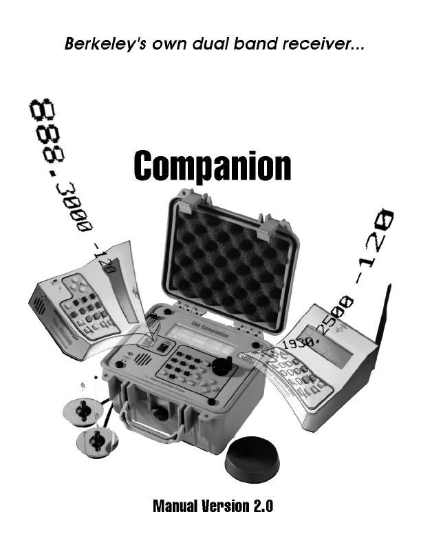
3 CAUTIONS Companion Manual GPS POWER SWITCH This switch (located to the left of the power on switch) should ONLY be switched when the unit's main power is OFF. NEVER turn the GPS ON or OFF while the COMPANION is running. IMPORTANT NOTE WHEN USING THE PC SERIAL PORT TO COLLECT DATA If the computer used to collect serial data boots up in Windows (3.1 or 95), do the following BEFORE attempting to save serial binary data in a disk file: a) Enter WINDOWS b) Select the MAIN menu (win 95 "Mycomputer") c) Select CONTROL PANEL, when in, select PORTS (win 95 system\device manager) d) Set COM 1 or COM 2 (depending on which is to be used) FLOW CONTROL to "HARDWARE" or "OFF". The normal setting for this option is "XON-XOFF". Flow Control MUST be set to the "HARDWARE" or "OFF" option for binary data collection to work reliably. Also note that when using laptops, POWER MANAGEMENT control MUST be turned OFF. This feature is usually found in the CONTROL PANEL, set it to OFF. If the power management control software puts the laptop in low power mode DURING data collection, data WILL be lost. INTRODUCTION The COMPANION is equipped with an 8 channel GPS receiver whose data is both displayed on the LCD and included in the serial output for post processing. The Companion is a dual RF receiver that measures RF in one of two modes: SINGLE FREQUENCY MODE Each receiver independently measures signal strength (in dbm) 200 times per second for the selected frequency of both receivers. The data is output simultaneously on the local back lit LCD display and through the serial port for collection on a PC for post processing. The demodulated FM signal of both receivers can be listened to using the built in speaker or headphone jack using the supplied headphone. The supplied MSDOS PC software is used to collect and save the RF data in a PC disk file. While the data is being collected, it can be viewed on the PC screen either in a text or graphic format. In order to use the graphic features of the PC software, the computer must be equipped with a VGA (color) display. The post process outputs of the PC software include: 1) Conversion of data to ASCII for import into EXCEL or MAP INFO. 2
4 2) Graph of either receivers data vs. position (LAT-LON). 3) Graph of either or both receivers dbm values vs. time. SCAN FREQUENCY MODE Each receiver can be programmed using the supplied PC software to scan and record signal strength of up to 80 frequencies for each receiver. The strongest frequency encountered at each scan is displayed on the LCD. In addition, all data for each scan is sent through the serial port for collection on a PC for post processing. The supplied MSDOS PC software is used to collect and save the RF data in a PC disk file. While the data is being collected, it can be viewed on the PC screen in a text format. In addition, the PC software contains a frequency/channel editor that is used to create receiver scan tables and to download the tables to the COMPANION. The SCAN mode is started and stopped via the PC serial port, the top panel controls (KNOB and all keys) are inactive when the unit is in the scan mode. SPECIFICATIONS Input Power MIN VDC Input Power MAX VDC DC Current AMP Receivers Standard Frequency Ranges (MHz) , (PCS) , (ETACS) (PAGING) (ISM) (SMR) , (EAMPS) Other ranges available upon request. Measurement Speed (Single Frequency Model) dbm per second (Both receivers) Sensitivity to -30 dbm +- 1db First IF MHz Second IF KHz Channel Step - Depends on type of receiver 12.5Khz to 50Khz Modulation... FM 3


5 INPUT, OUTPUTS and CONTROLS TOP PANEL MAIN POWER switch - Use to turn COMPANION on and off. GPS POWER switch - Use to turn on and off the GPS receiver. Use this switch only when the MAIN POWER switch is OFF. GPS antenna MUST be connected to the back panel GPS antenna input BEFORE the MAIN POWER switch is turned on. The GPS POWER switch is used to conserve power in situations where GPS is not required and the COMPANION is being powered by an external battery. Both the MAIN POWER and GPS POWER switch have a built in indicator lamp that is lit when the switch in question is on. SELECTION KNOB -The selection knob is used in conjunction with the display to adjust the currently selection parameter. The knob can be used to: Adjust receiver 1 or 2 frequency Adjust receiver 1 or 2 volume There is also a 'LOCK' selection which disables the knob from changing any parameter. KEYPAD -The 20 key keypad is used to enter frequencies and to enter setup information. CONTRAST -Use to adjust the contrast (viewing angle) of the LCD display. HEADPHONE -Connect the supplied headphones to this jack to listen to the demodulated signal of either receiver. Before using the headphones, adjust the volume using the built in speaker to a low level. Then plug in the headphone and adjust the volume to a comfortable level. 4

6 BACK PANEL INPUT-OUTPUT CONNECTOR RF INPUT - RECEIVER 1TNC +13dBm MAX RF INPUT - RECEIVER 2TNC +13dBm MAX GPS ANTENNA INPUTSMA (see note below) RS232 SERIAL DATA IN\OUTDB9 Female DC POWER INPUT4 PIN Male UNIT OPERATION Note: GPS ANTENNA INPUT This connector supplies 5 Volt power to the supplied GPS antenna. ONLY CONNECT the supplied GPS antenna to this connector when the MAIN POWER SWITCH is in the OFF position. DO NOT connect any other antenna but the supplied GPS ANTENNA to this connector. Connection of other than the supplied GSP ANTENNA to this input MAY damage the GPS receiver. TURN ON - If using the GPS receiver, connect the supplied GPS antenna to the back panel GPS antenna input and turn on the GPS POWER switch, making sure the MAIN POWER switch is OFF. Turn on the MAIN POWER switch, the display will turn on and the power up screen will be displayed: POWER UP SCREEN The unit will exit this screen in 15 seconds unless a key is pressed before this time elapses. Use this screen to determine ROM firmware revision # (the number to the right of the letter 'V' on the top line) receiver types (frequency), serial number and last calibration date (mmddyy). After the POWER UP SCREEN is displayed, the unit will begin measuring the last two frequencies the unit had been set to when the MAIN POWER switch was last turned off in the SINGLE FREQUENCY MODE. If the unit was last used in the SCAN MODE, the Companion will start measuring the strongest frequency last scanned by both receivers in the SINGLE FREQUENCY MODE. To resume the SCAN MODE, the PC must be used to re-start scanning the receiver scan tables. SINGLE FREQUENCY MEASUREMENT SCREEN Whenever this display screen is active, the COMPANION is measuring the indicated frequencies and data is being output from the RS232 serial connector. 5
7 SINGLE FREQUENCY MODE DISPLAY SCREEN Measurement Data Display: Receiver 1 is measuring -93dbm at MHz Receiver 2 is measuring -115dbm at MHz :21:11 MARKER 1001 Current date is June 3, 1997 Current time is 9:21:11 am (time is displayed in 24 hour format) Marker value is currently 1001 LA N LO W LOCKED 4 Current latitude is 40 deg min North Current longitude is 74 deg min West The GPS receiver is locked and tracking 5 satellites Current Selection Knob Parameter (active option is highlighted): FREQ1 - if highlighted, KNOB adjusts receiver 1 frequency, ENTER key changes receiver 1 Frequency, SEEK UP/DOWN keys cause receiver 1 to seek up or down VOL1 - if highlighted, KNOB adjusts receiver 1 volume FREQ2 - if highlighted, KNOB adjusts receiver 2 frequency ENTER key changes receiver 2 Frequency, SEEK UP/DOWN keys cause receiver 2 to seek up or down VOL2 - if highlighted, KNOB adjusts receiver 2 volume LOCK - if highlighted, KNOB locked, turning the KNOB has no effect UP and DOWN ARROW keys are used to change the highlighted KNOB parameter while in the measurement screen. For AMPS and ETAC receivers, the channel number to frequency conversion is as defined by the AMPS and TACS specification. For all other receivers, channel number 1 corresponds to the receiver base frequency (as displayed on the POWER UP screen). Each successive channel number to frequency uses the following formulas: Freq = ((Chan# - 1) * ChanStep (KHz)) + Base Frequency Chan # = ((Frequency - Base Frequency) / Chan Step) + 1 6

8 SINGLE FREQUENCY MODE DISPLAY EXAMPLE CHANNEL NUMBER DISPLAY EXAMPLE KEYPAD Keys Usage 1-9 & 0 Entry of frequencies, channel numbers and setups. 0 Pressing the 0 key while displaying the measurement screen will change between channel number and frequency for both receiver 1 and 2. SETUP- Enter COMPANION SETUP SCREENS SEEK UP- Current Selected receiver SEEKS UP in frequency until a frequency is found that is >= the SEEK dbm threshold. (FREQ1 or FREQ2 must be highlighted) SEEK DOWN- Current Selected receiver SEEKS DOWN in frequency until a frequency is found that is >= the SEEK dbm threshold. (FREQ1 or FREQ2 must be highlighted) The SEEK db threshold is set in the SETUP screen. When SEEKing UP or DOWN, the receivers step up or down by single increments of the fixed channel step. MARKER- Press to increment the measurement marker number. Use to mark areas of interest during measurement. ESC- Use to exit setups, has no effect during measurement. 7 ENTER- If FREQ1 or FREQ2 is highlighted, pressing the enter key allows entry of either RX 1
9 or RX 2 measurement frequency (using the numeric keys rather than the KNOB). SELECT UP ARROW - Change the KNOB select highlight. SELECT DOWN ARROW - Change the KNOB select highlight. ENTRY RIGHT ARROW - No effect in measurement screen. When in setup or chan-freq entry, move input highlight right. ENTRY LEFT ARROW - No effect in measurement screen. When in setup or chan-freq entry, move input highlight left. SCAN FREQUENCY MEASUREMENT SCREEN EXAMPLE Whenever this display screen is active, the COMPANION is in the SCAN FREQUENCY mode and data is being output from the RS232 serial connector. The frequencies and dbm values displayed are the strongest found during each scan through the receiver scan tables. SCAN FREQUENCY TABLE DISPLAY SCREEN When in the SCAN MODE, the COMPANION is under the control of the PC. The keys and KNOB are inactive SCAN MODE :04:52 MARKER 27 LA N LO W LOCKED 4 Measurement Data Display: The strongest frequency encountered during the previous scan of Receiver 1 scan table was -93dbm at MHz The strongest frequency encountered during the previous scan of Receiver 2 scan table was -115dbm at MHz :04:52 MARKER 27 Current date is February 19, 1997 Current time is 5:04:52 pm (time is displayed in 24 hour format) Marker value is currently 27 LA N LO W LOCKED 4 Current latitude is 40 deg min North Current longitude is 74 deg min West The GPS receiver is locked and tracking 4 satellites SETUP Pressing the SET-UP key causes the COMPANION to enter the setup screen. 8
10 SETUP SCREEN Highlight item using UP/DOWN arrows Press ENTER to change Highlighted item Press ESC to return from setup To change DATE/TIME, SEEK THRESHOLD or MARKER, highlight the selection using the up and down arrow key and press ENTER. SET DATE/TIME SCREEN 5 pm). Press ENTER to set DATE/TIME as entered. Enter the 2 digit (leading zero if < 10) month, 2 digit (leading zero if < 10) day, and 2 digit (leading zero if < 10) year. Enter the 2 digit (leading zero if < 10) hour, 2 digit (leading zero if < 10) minute, and 2 digit (leading zero if < 10) seconds. Time MUST be entered in 24 hour format (example, enter 17 for SET SEEK THRESHOLD SCREEN Enter the 3 digit (leading zero if < 100) dbm threshold used by SEEK UP and SEEK DOWN keys. Press ENTER to set the entered threshold. SET MARKER SCREEN Enter the 4 digit (leading zero's required) MARKER #. Press ENTER to use the entered MARKER number. PC SOFTWARE INSTALLATION Create a directory on the PC that will be used to collect and post process the COMPANION serial data. Change to that directory and copy all files from the supplied disk to this directory. 9

11 EXAMPLE Companion Manual TYPE:EFFECT md compan<enter>make directory "COMPAN" cd compan<enter>change to directory "COMPAN" copy a:*.*<enter>copy all files from the supplied disk in drive A to the directory "COMPAN" USING THE PC SOFTWARE Connect the COMPANION to the PC serial port COM 1 or COM 2 using the supplied RS232 serial cable. Run the supplied MSDOS program COMPAN.EXE, type COMPAN<ENTER> The program will prompt: Use COM Port 1 or 2? Press 1 if using PC COM port 1, press 2 if using PC COM port 2. The program will now display the MAIN MENU: BVS COMPANION SERIAL PORT Interface V1.01 Copyright (c) 1997 Berkeley Varitronics Systems, Inc.,Metuchen, N.J SINGLE FREQUENCY MEASUREMENT MENU Press: T text display of COM 1 Single Frequency data and save on disk G graph display of COM 1 Single Frequency data and save on disk C display Single Frequency file data and convert to ASCII P to plot Single Frequency file vs. Lat-Lon D to plot Single Frequency file vs. dbm F for Frequency Scan Menu Esc to return to DOS 10
12 SINGLE FREQUENCY MEASUREMENT MENU OPTIONS T - Display (and save to disk) COMPANION data in a text format. G - Display (and save to disk) COMPANION data as a graph of dbm vs. time. Press 'T' or 'G' depending on the display desired, the program will prompt: Save Single Frequency DATA to File: Enter an MSDOS file name to save the binary data in for further post processing. If it is not desired to save the serial data, just press ENTER. The TEXT or GRAPHIC screen will be displayed, and within one second, data will be displayed. IF no data is displayed within one second, check that the cable is connected to the COMPANION and that the COMPANION is in the measurement screen. To stop the PC display (and close the binary save file), press the PC ESC key. The PC will return to the MAIN MENU. NOTE: To use ANY of the graphics options, the PC used to run the supplied software must be equipped with a color VGA display system. MONOCHROME VGA will work, but it will be difficult to view the graphs since many items are color coded. Receiver 1 dbm is plotted in BLUE, receiver 2 dbm in GREEN, X axis is time, Y axis is dbm. SPECIAL PC KEYS WHILE IN THE SINGLE FREQUENCY TEXT DISPLAY F1 - change Receiver 1 frequency F2 - change Receiver 2 frequency F3 - Scan receiver 1 table and resume measuring on the strongest frequency. F4 - Scan receiver 2 table and resume measuring on the strongest frequency. F5 - Scan both receiver tables, resume measuring on the strongest frequencies. C - current receiver frequencies displayed as Channel #'s F - current receiver frequencies displayed as Frequency (MHz) M - increment Marker # SPECIAL PC KEYS (GRAPHIC or TEXT) DISPLAY 11
13 ESC - Stop display of data, CLOSE save binary file (if it had been specified) and return to the SINGLE FREQUENCY MENU. C - Display Single Frequency file data (saved using option 'T' or 'G') in text and convert to ASCII format. To create ASCII files for import into EXCEL or MAP INFO, option 'C' MUST be used. Press 'C', the program will prompt: Name of Single Frequency binary file to Display and Convert: Enter the name given to the binary file saved in the 'T' or 'G' option screen. The program will now prompt: MAPINFO,PLANET,EXCEL or RAW DATA Tab delimited OUTPUT Enter FILE NAME for disk file output Or press ENTER for output to terminal only: If it is not desired to create an ASCII file, press ENTER. If the ASCII file is destined to be imported into EXCEL, enter a file name for the ASCII data with an extension 'XL'. EXAMPLE EXCEL ASCII FILE NAME: DRIVE.XL If the ASCII file is destined to be imported into MAP INFO, enter a file name for the ASCII data with an extension 'TXT'. EXAMPLE MAP INFO ASCII FILE NAME: DRIVE.TXT The program will now prompt: Press M for Mapinfo-Planet format E for EXCEL format R for RAW DATA format? If the ASCII file is destined to be imported into MAP INFO, press 'M', press 'E' for EXCEL format. To convert ALL dbm data into ascii, press 'R' for RAW DATA format. The program will display the data in the binary file and create the ASCII file. The MAIN MENU will be displayed when the conversion is complete. P - Use to plot Binary Data file saved with the 'G' or 'T' option, dbm vs. Position (Latitude-Longitude). This Plot will display either Receiver 1 or 2 dbm vs. position. If using this plot, make sure that while the data is collected, the frequency of the receiver to be plotted is not changed. Press 'P' The program will prompt: 12
14 Name of Disk File to plot: Enter the name given to the binary file saved in the 'T' or 'G' option screen such as "DRIVE.BIN". The program will now prompt: Press 1 to plot RX 1, 2 to plot RX 2 Press 1 to display receiver 1 dbm vs. position, press 2 to display receiver 2 dbm vs. position. The program will respond: Scanning File Drive.bin Wait while the program scan's all of the data to determine the range of LAT-LON and dbm for the selected receiver. When the scan is complete, the program will display the requested receiver dbm vs. position. To the left of the Y axis, the frequency, date and color coded dbm scale is displayed. The Y axis is LATITUDE, the X axis is LONGITUDE. When the plot is complete, the program will display: Done... Press Any Key in the lower left hand corner of the display. Press any key to return to the main menu. D - Use to plot Binary Data file saved with the 'G' or 'T' option, dbm vs. Time. This Plot will display either Receiver 1 or 2 or both dbm vs. time. Press 'D' The program will prompt: Name of Disk File to plot: Enter the name given to the binary file saved in the 'T' or 'G' option screen such as "DRIVE.BIN". The program will now prompt: Press 1 to plot RX 1, 2 to plot RX 2, B to plot Both Press 1 to display receiver 1 dbm vs. time, press 2 to display receiver 2 dbm vs. time, press 'B' to display both receiver 1 and 2 dbm vs. time. The program will display the first two second's worth of data in the following format: 13
15 Y axis is dbm X axis is time The max fade for the two seconds of data is marked for either or both receiver by RED dotted lines on the graph and in text to the left of the Y axis. When viewing both receivers data, receiver 1 is plotted in BLUE, receiver 2 in GREEN. To the left of the Y axis the LAT-LON, Date, Marker and frequency(s) are displayed. After the first 2 seconds of data is displayed, the screen will pause. To continue single stepping, press the SPACE BAR, to stop the display and return to the MAIN MENU, press ESC. To display the data without pausing (FREE RUN), press the 'F' key. To resume single stepping, press the SPACE BAR to stop free running. To step backward, press the 'L' key to display the previous 2 seconds of data. Press the 'M' key to move forward to the point in the file where the MARKER value changes. When the end of data in the disk file is reached, the program will display: Done... Press Any Key in the lower left hand corner of the display. Press any key to return to the main menu. F - Enter the FREQUENCY SCAN MENU FREQUENCY SCAN MENU Press: T text display of COM 1 RF SCAN data and save on disk C convert RF SCAN file data to ASCII E for FREQUENCY SCAN EDIT Menu Esc to return to SINGLE FREQUENCY MENU? FREQUENCY SCAN MENU OPTIONS T - Start SCANNING the receiver 1 and 2 scan tables and save data in a disk file for later post processing. Data is displayed in text as received. During the display of the data the following PC keys are used to change the data displayed: F1 - display Receiver 1 data F2 - display Receiver 2 data C - current receiver frequencies displayed as Channel #'s F - current receiver frequencies displayed as Frequency (MHz) ESC - Stop scanning measurement, close the binary disk file and return to the FREQUENCY SCAN MENU. Press 'T', the program will prompt: Save SCAN FREQUENCY DATA to File: Enter an MSDOS file name to save the binary data in for further post processing. If it is not desired to save the serial data, just press ENTER. As soon as the results of the first scan of both receivers is available, it will be 14
16 displayed in text. Do NOT turn off the COMPANION until the SCAN MODE is stopped by the PC or some setups could be lost. C - Convert saved binary scan file to ASCII TAB Delimited format for import into EXCEL or MAP INFO. Press 'C', the program will prompt: Name of SCAN FREQUENCY binary file to Convert: Enter the name given to the binary scan file saved in the 'T' option. The program will now prompt: MAPINFO,PLANET or EXCEL Tab delimited OUTPUT Enter FILE NAME for disk file output: If the ASCII file is destined to be imported into EXCEL, enter a file name for the ASCII data with an extension 'XL'. EXAMPLE EXCEL ASCII FILE NAME: DRIVE.XL If the ASCII file is destined to be imported into MAP INFO, enter a file name for the ASCII data with an extension 'TXT'. EXAMPLE MAP INFO ASCII FILE NAME: DRIVE.TXT The program will now prompt: Press M for Mapinfo-Planet format E for EXCEL format If the ASCII file is destined to be imported into MAP INFO, press 'M', press 'E' for EXCEL format. The program will now prompt: Convert Receiver 1, 2 or Both Press 1 for Receiver 1, 2 for Receiver 2, B for Both? Press 1 - Only receiver 1 data is converted to ascii. 2 - Only receiver 2 data is converted to ascii. B - Both receivers data is converted to ascii. 15
17 The program will now prompt (for receiver 1, 2 or both): Save RX1 Frequency or Channel # Press F for Frequency, C for Channel #? Press F if the frequencies scanned should be saved in row one in MHz, press C if the frequencies scanned should be saved in row one as channel #'s. The program will now convert the binary file to ascii and return to the FREQUENCY SCAN MENU when the conversion is complete. E - Enter the FREQUENCY SCAN EDIT MENU FREQUENCY SCAN EDIT MENU Press: R to Read SCAN TABLE disk file W to write SCAN TABLE to disk file V to view SCAN TABLE D to DOWNLOAD Scan Tables to COMPANION E to EDIT Frequency Scan Tables I to list EDIT Frequency Table Instructions Esc to return to FREQUENCY SCAN MENU? FREQUENCY SCAN EDIT MENU OPTIONS R - Read in a previously saved SCAN TABLE disk file for editing or downloading to COMPANION. Press 'R', the program will prompt: Name of Frequency Table file to read: Enter the name of a previously saved Frequency Table file. V - To view the contents of a SCAN TABLE Press 'V', the program will prompt: 16
18 Press 1 for Receiver 1, 2 for Receiver 2? Press 1 to view receiver 1 portion of the table, press 2 to view receiver 2 portion of the table. Press any key after the table is displayed to return to the FREQUENCY SCAN EDIT MENU. FREQUENCY SCAN EDIT MENU OPTIONS W - Write the current SCAN TABLE to disk file for future use. Press 'W', the program will prompt: Save Frequency Table to File: Enter an MSDOS file name for the Frequency Scan Table file. Use this same name with the 'R' option to reload the SCAN TABLE in the future. D - Download the current SCAN TABLE to the COMPANION battery backed memory. To Download the current table to the COMPANION, do the following. Step: 1) Connect the COMPANION to the PC serial port COM 1 or COM 2 using the supplied RS232 serial cable. 2) Make sure the COMPANION is in the SINGLE FREQUENCY MODE (see page 7). 3) Press 'D', when the download is complete, the program will return to the FREQUENCY SCAN EDIT MENU. Verify the DOWNLOAD by using the FREQUENCY SCAN MENU 'T' option BEFORE collecting data. FREQUENCY SCAN EDIT MENU OPTIONS E - to enter the Frequency Scan Table EDITOR I - list EDITOR Instructions Press 'I', the program will display the EDITOR instructions, press any key to return to the FREQUENCY SCAN EDIT MENU. Press 'E', the program will prompt: Press 1 for Receiver 1, 2 for Receiver 2? Press 1 to edit receiver 1 portion of the table, press 2 to edit receiver 2 portion of the table. FREQUENCY SCAN TABLE EDITOR 17
19 NOTE - Make sure the PC Num Lock is off before using the editor. If the Num Lock is ON, the arrow keys will not work. The current entry position is marked by the > character, to the left of either the frequency or the channel number. To enter frequency, press F (which moves > to the left of the current frequency), to enter channel numbers press C (which moves > to the left of the current channel number). Use the ARROW (UP,DOWN,RIGHT,LEFT) keys to move the position of the current entry marker. To erase the current entry, press the DEL key. Both channel number and frequency will be set to zero. The Companion does not measure any entry in the table that is set to zero. To enter either current frequency or channel number, type the first digit of the new frequency or channel number. Use the BACKSPACE key to erase incorrectly entered digits. FREQUENCY SCAN TABLE EDITOR - CONTINUED Press ENTER to save the entered frequency or channel number in the current table position. The marker will be automatically moved down to the next position in the table. Press ESC to return to the FREQUENCY SCAN EDIT MENU. Always remember to SAVE edited tables with the 'W' option BEFORE returning to MSDOS, or the edited data will be lost and have to be re-entered. DATA SAVE FORMAT - SINGLE FREQUENCY BINARY /*Single Frequency structure*/ /*header - follows trigger and int count*/ structpcs_head { byte pcssec;/* real time sec */ byte pcsmin;/* min */ byte pcshr;/* hour */ byte pcsday;/* day */ byte pcsmon;/* mon */ byte pcsyr;/* year */ byte pcsnavs;/* navigation status */ byte gpslat[5];/* gps position - lat */ byte gpslon[5];/* lon */ byte gpstim[3];/* gps time */ word pcsmrk;/* current user marker # */ }; /*DATA record - follows header, pcs_head.pcsndr records*/ structpcs_data { 18
20 word pcsch;/* chan # */ byte pcsgif;/* GHz flag, is54 (amps) flags */ word pcs_bmh;/* base F Mhz */ word pcs_bkh;/* Khz */ word pcs_stp;/* chan step in khz */ byte pcssat;/* sat */ word pcs_drsv;/* reserved */ byte pcs_ndb;/* number of rssi in buffer (200) */ byte pcs_dbb[200];/* rssi buffer */ }; structpcs_buf { structpcs_head ph;/* header */ structpcs_data prec[2];/* record array */ }; SINGLE FREQUENCY ASCII DATA SAVE FORMATS EXCEL FORMAT col ascii :12: OK columnascii data 1row 2time 3date 4marker 5gps status 6lat 7lon 8Rx 1 frequency 9Rx 1 dbm (average of 200 dbm readings) 10Rx 2 frequency 11Rx 2 dbm (average of 200 dbm readings) MAP INFO FORMAT col ascii columnascii data 1lat 2lon 3Rx 1 frequency 19
21 4Rx 1 dbm (average of 200 dbm readings) 5Rx 2 frequency 6Rx 2 dbm (average of 200 dbm readings) In both ASCII formats, each column field is seperated by a single TAB (09H) character. Each line ends with a CR LF (0DH,0AH). RAW DATA FORMAT col1 2 3 ascii columnascii data 1sample # 2receiver 1 dbm 3receiver 2 dbm The time between each consecutive sample # is 5 milli seconds so that each one seconds worth of data contains 200 dbm values. This output format provides the un-averaged data that could be used to analyze RF fading. BINARY DATA SAVE FORMAT - SCAN FREQUENCY MODE /* infromation about receiver */ struct rx_info { byte gif;/* GHz flag, is54 (amps) flags */ word bmh;/* base F Mhz */ word bkh;/* Khz */ word stp;/* chan step in khz */ }; /* scan table structure that is downloaded to receiver */ struct scan_table { struct rx_info rx1_info; struct rx_info rx2_info; 20
22 word scan_list_rx1[80];/* rx1 chan list */ word scan_list_rx2[80];/* rx2 chan list */ }; note: CHAN # 0 is skipped by receivers (not scanned). struct scan_data { word schan;/* channel */ byte srssi;/* rssi (dbm) */ }; /* scan data sent by receiver to PC */ structpcs_scan_data { struct pcs_head ph;/* header (pg. 27) */ struct rx_info scn1_info;/* rx1 info */ struct rx_info scn2_info;/* rx2 info */ struct scan_data rx1_sd[80];/* rx1 chan, rssi data */ struct scan_data rx2_sd[80];/* rx2 chan, rssi data */ }; ASCII SCAN DATA FORMATS For both EXCEL and MAP INFO ASCII formats, ROW 1 is a header that contains an ASCII string that describes the data in each column. This includes the frequencies (or channel numbers). The dbm readings for each frequency are in the column under the frequency or channel number in ROW 1. SCAN DATA - EXCEL FORMAT col row 1 Meas #Time Date Marker GPS Lat LON row :12: OK Row 1 is an ascii header containing: columnascii data 1Meas (row) # 2time 3date 4marker 5gps status 21
23 6lat 7lon 8frequency/chan 1 9frequency/chan Following the Longitude, starting at column 8, is the list of frequencies or channel numbers measured. Receiver 1 frequencies or channel numbers are first followed by receiver 2 if BOTH receivers are included in the ascii file. Skipped channels are not listed. Row 2 through end of file. Following row 1 is the scan data in the columns as shown above. dbm for each frequency is in the column under the ascii frequency or channel # in row 1. SCAN DATA - MAP INFO FORMAT col row 1 Lat LON row Row 1 is an ascii header containing: columnascii data 1lat 2lon 3frequency/chan 1 4frequency/chan Following the Longitude, starting at column 3, is the list of frequencies or channel numbers measured. Receiver 1 frequencies or channel numbers are first followed by receiver 2 if BOTH receivers are included in the ascii file. Skipped channels are not listed. Row 2 through end of file. Following row 1 is the scan data in the columns as shown above. dbm for each frequency is in the column under the ascii frequency or channel # in row 1. 22
24 dbm to Watts CONVERSION dbm microwatts dbm nanowatts dbm picowatts
25 Glossary of Acronyms AC alternating current A/D or ADC analog to digital converter AGC automatic gain control BER bit error rate BPSK binary phase shift keying BW band width CDMA Code Division Multiple Access (spread spectrum modulation) DC direct current D/A digital to analog db decibel dbm decibels referenced to 1 milliwatt DOS digital operating system DSP digital signal processing FIR finite impulse response GHz gigahertz GPS geographical positioning system (satellite based) GPS diff. GPS error correction signal which enhances GPS accuracy IF intermediate frequency I and Q In phase and Quadrature khz kilohertz kw-hr kilowatt-hour LCD liquid crystal display LO local oscillator ma milliampere Mbits megabits MHz megahertz modem acronym for modulator/demodulator mw milliwatt PCMCIA personal computer memory card international association PC personal computer PCS personal communications service (1.8 to 2.1 GHz) PN pseudo noise QPSK quaternary phase shift keying, 4-level PSK RF radio frequency RSSI receiver signal strength indicator UTC universal coordinated time µ micro (106) VAC volts alternating current VGA video graphic VSWR voltage standing wave ratio X horizontal axis Y vertical axis 24
26 If you require technical assistance, or service to your Companion, please contact: Berkeley Varitronics Systems, Inc. Liberty Corporate Park Berkeley Varitronics Systems, Inc. 255 Liberty Street Metuchen, NJ Tel:(732) Fax:(732) :00am - 6:00pm Eastern Time 25
Dragon. manual version 1.6
 Dragon manual version 1.6 Contents DRAGON TOP PANEL... 2 DRAGON STARTUP... 2 DRAGON STARTUP SCREEN... 2 DRAGON INFO SCREEN... 3 DRAGON MAIN SCREEN... 3 TURNING ON A TRANSMITTER... 4 CHANGING MAIN SCREEN
T r o t r o t i o se
 Tortoise manual version 2.1 Contents TORTOISE TOP PANEL... 2 TORTOISE REAR PANEL... 2 STARTUP... 3 MAIN PARAMETERS... 3 MAIN MENU... 4 INFORMATION... 4 FEATURES... 4 SET INCREMENTS... 5 MISC SETTINGS...
T r o t r o t i o se
 Tortoise manual version 1.8 Contents TORTOISE TOP PANEL... 2 TORTOISE REAR PANEL... 2 TORTOISE MAIN DISPLAY... 3 PARAMETER MODIFICATION... 3 TORTOISE UNIT DATA SCREEN 1... 3 TORTOISE UNIT DATA SCREEN 2...
SNG-2150C User s Guide
 SNG-2150C User s Guide Avcom of Virginia SNG-2150C User s Guide 7730 Whitepine Road Revision 001 Richmond, VA 23237 USA GENERAL SAFETY If one or more components of your earth station are connected to 120
Noise Detector ND-1 Operating Manual
 Noise Detector ND-1 Operating Manual SPECTRADYNAMICS, INC 1849 Cherry St. Unit 2 Louisville, CO 80027 Phone: (303) 665-1852 Fax: (303) 604-6088 Table of Contents ND-1 Description...... 3 Safety and Preparation
JD725A Cable and Antenna Analyzer - Dual Port
 COMMUNICATIONS TEST & MEASUREMENT SOLUTIONS JD725A Cable and Antenna Analyzer - Dual Port Key Features Portable and lightweight handheld instrument Built-in wireless frequency bands as well as the most
EAMPS manual version 3.8
 EAMPS manual version 3.8 SECTION PAGE OPERATIONAL TIPS - BEFORE YOU START 3 INTRODUCTION 4 Overview 5 General Features 5 Keypad 5 Fox Rear Panel 5 Charging/Fast Charging 5 GPS Power Switch 5 FOX MAIN MENU
FLEX/POCSAG manual version 4.0
 FLEX/POCSAG manual version 4.0 SECTION PAGE OPERATIONAL TIPS - BEFORE YOU START 3 INTRODUCTION 4 Overview 5 General Features 5 Keypad 5 Fox Rear Panel 5 Charging/Fast Charging 5 GPS Power Switch 5 FOX
Yellow Frog. Manual Version 1.1
 Yellow Frog Manual Version 1.1 1 YellowFrog Contents PC Requirements...... 2 YellowFrog Power Meter Measurement.... 3 YellowFrog PC Software..... 3 Main Screen....... 4 Input Overload....... 5 Battery
SATELLITE FINDER SK-3200 USER MANUAL
 SATELLITE FINDER SK-3200 USER MANUAL CONTENTS 1. GUIDE...1 1.1 IMPORTANT SAFETY INSTRUCTIONS... 1 1.2 UNPACKING...1 1.3 PRODUCT OVERVIEW & ILLUSTRATION... 2 2. OUTLINE...4 3. THE MENU OSD INSTRUCTION...5
Satellite locator WS-6933
 R Satellite locator WS-6933 User's Manual English CONTENTS 1. GUIDE...2 1.1 IMPORTANT SAFETY INSTRUCTIONS...2 1.2 UNPACKING...2 1.3 PRODUCT OVERVIEW&ILLUSTRATION...3 2. OUTLINE...4 3. THE MENU OSD INSTRUCTION...5
DIVERSITY DVB-T RECEIVER (DDR)
") User s Manual The most important thing we build is trust. DIVERSITY DVB-T RECEIVER (DDR) Cobham Surveillance GMS Products 1916 Palomar Oaks Way Ste 100 Carlsbad, CA 92008 100-M0062X2 T: 760-496-0055 05/15/09
User s Manual The most important thing we build is trust. DIVERSITY DVB-T RECEIVER (DDR) Cobham Surveillance GMS Products 1916 Palomar Oaks Way Ste 100 Carlsbad, CA 92008 100-M0062X2 T: 760-496-0055 05/15/09
MANUAL ENG DT-2100 ENGLISH QPSK
 ENG-1 010326 00983 ENGLISH 49 64 QPSK 00983-4 ENG-1.p65 49 A versatile digital receiver with a guaranteed future One of the advantages with is the flexible design. The receiver is equipped with a Common
MENU EXECUTE Shiloh Road Alpharetta, Georgia (770) FAX (770) Toll Free
 FAX (770) Toll Free") Instruction Manual Model 2016-1250 Downconverter May 2009 Rev A F=2501.750 G=+25.0 MENU MODEL 2016 DOWNCONVERTER CROSS TECHNOLOGIES INC. ALARM REMOTE POWER EXECUTE Data, drawings, and other material contained
Instruction Manual Model 2016-1250 Downconverter May 2009 Rev A F=2501.750 G=+25.0 MENU MODEL 2016 DOWNCONVERTER CROSS TECHNOLOGIES INC. ALARM REMOTE POWER EXECUTE Data, drawings, and other material contained
M5-H002. Multiview T-35. DVB-T to PAL / 5 channels on all TV s
 120531 M5-H002 Multiview T-35 DVB-T to PAL / 5 channels on all TV s Contents Multiview... 3 Features... 3 Caution... 3 Front & Rear Panel... 4 Connecting... 5 Programming... 6 Information... 7 Installation...8
Stevens SatComm FAQs For use with SatCommSet or Terminal Setup programs
 Stevens SatComm FAQs For use with SatCommSet or Terminal Setup programs Q. What are the channel assignments for On Air Test Mode? A. The assigned GOES test channels are as follows: GOES West 300 Baud:
SZU OPERATING INSTRUCTIONS SAT NAVI
 SZU 21-00 O P ER ATI N G I N S T R U C T I O N S SAT NAVI Operation Instructions SZU 21-00 Safety Notes Turn off the receiver or any used power supply before installing, to avoid short-circuit. Installation
Sunrise Telecom, Hukk Division
 Established 1981 Advanced Test Equipment Rentals www.atecorp.com 800-404-ATEC (2832) Sunrise Telecom, Hukk Division CR1200R Manual Contents (Rev. B) CHAPTER 1 - GENERAL INFORMATION A general description
Keysight FieldFox Microwave Analyzers
 Quick Reference Guide Contents Keysight FieldFox Microwave Analyzers Do you have everything?... 1 The Power Button and LED... 1 Battery Usage... 2 Measure Return Loss (CAT Mode)... 3 Measure 1-Port Cable
Model 7330 Signal Source Analyzer Dedicated Phase Noise Test System V1.02
 Model 7330 Signal Source Analyzer Dedicated Phase Noise Test System V1.02 A fully integrated high-performance cross-correlation signal source analyzer from 5 MHz to 33+ GHz Key Features Complete broadband
LPT-2250 Spectrum Analyzer Operation Manual
 LPT-2250 Spectrum Analyzer Operation Manual 1999 LP Technologies, Inc. All rights reserved Document # 070-1500-0001, Rev E Table of Contents 1.0 GENERAL DESCRIPTION AND FEATURES...3 2.0 USAGE PRECAUTIONS
MANUAL ENG DT-2200 ENGLISH QPSK
 ENG-1 011001 01042 ENGLISH 49 64 QPSK 01042-4 ENG-1.p65 49 A versatile digital receiver with a guaranteed future One of the advantages with is the flexible design. The receiver is equipped with a Common
RS232 Connection. Graphic LCD Screen. Power Button. Charger Adapter Input LNB Output. MagicFINDER Digital SatLock Operating Manual
 GENERAL FEATURES Easy-to-understand user-friendly menu and keypad. LNB short circuit protection. Display of Analog Signal Level, Digital Signal Quality with % and Bar, audible notification. Timer Lock,
PSM-2100L Satellite Modem L-Band IF Addendum
 DATUM SYSTEMS PSM-2100L Satellite Modem L-Band IF Addendum 1.0 Introduction Small receive only satellite stations have used L-Band as an outdoor to indoor equipment IF link for several years. The advent
MAXTECH, Inc. BRC-1000 Series. C-Band Redundant LNB Systems. Technology for Communications. System Block Diagrams
 MAXTECH, Inc. Technology for Communications BRC-1000 Series C-Band Redundant LNB Systems Introduction Redundant LNB systems minimize system downtime due to LNB failure by providing a spare LNB and an automatic
7000 Series Signal Source Analyzer & Dedicated Phase Noise Test System
 7000 Series Signal Source Analyzer & Dedicated Phase Noise Test System A fully integrated high-performance cross-correlation signal source analyzer with platforms from 5MHz to 7GHz, 26GHz, and 40GHz Key
Night Hawk Firing System User s Manual
 Firmware Version 2.53 Page 1 of 37 Table of Contents Features of the Night Hawk Panel... 4 A reminder on the safe use of Electronic Pyrotechnic Firing Systems... 5 Night Hawk Firing Panel Controls... 6
SIDC-5004 VHF/UHF WIDEBAND TUNER/CONVERTER. FREQUENCY RANGE: 20 to 3000 MHz
 SIDC-5004 VHF/UHF WIDEBAND TUNER/CONVERTER FREQUENCY RANGE: 20 to 3000 MHz High Dynamic Range Enables the End User to Reject Blocking Signals Often Undetected by Less Sensitive Tuners High Dynamic Range
Xsarius Satmeter Pro. Manual
 Xsarius Satmeter Pro Manual 1 2 Directory of content Introduction Directory of content 3 Introduction 3 Satmeter Pro 02 Frontpanel & buttons 6 Xsarius provides high quality products that enable you to
XR-3 QAM 8VSB. Modular Test Instrument. XR-3 Rugged Adaptable Economically Efficient Configurable to test: and more
 XR-3 Modular Test Instrument XR-3 Rugged Adaptable Economically Efficient Configurable to test: and more QAM 8VSB XR-3 Modular Test Instrument GENERAL FEATURES Durable case with rubber shock guards Color
Ku-Band Redundant LNB Systems. 1:1 System RF IN (WR75) TEST IN -40 db OFFLINE IN CONTROLLER. 1:2 System POL 1 IN (WR75) TEST IN -40 db POL 2 IN
 TEST IN -40 db OFFLINE IN CONTROLLER. 1:2 System POL 1 IN (WR75) TEST IN -40 db POL 2 IN") BRK-1000 Series Ku-Band Redundant LNB Systems Introduction Redundant LNB systems minimize system downtime due to LNB failure by providing a spare LNB and an automatic means of switching to the spare upon
BRK-1000 Series Ku-Band Redundant LNB Systems Introduction Redundant LNB systems minimize system downtime due to LNB failure by providing a spare LNB and an automatic means of switching to the spare upon
LPT-3000 Remote User s Guide (LPT-3000R) LP Technologies
 LP Technologies") 99 Washington Street Melrose, MA 02176 Phone 781-665-1400 Toll Free 1-800-517-8431 Visit us at www.testequipmentdepot.com LPT-3000 Remote User s Guide (LPT-3000R) LP Technologies 1 Table of Contents Chapter
99 Washington Street Melrose, MA 02176 Phone 781-665-1400 Toll Free 1-800-517-8431 Visit us at www.testequipmentdepot.com LPT-3000 Remote User s Guide (LPT-3000R) LP Technologies 1 Table of Contents Chapter
Agilent FieldFox RF Analyzer N9912A
 Contents Agilent FieldFox RF Analyzer N9912A Quick Reference Guide Do You Have Everything?... 2 The Power Button and LED... 2 Battery Usage... 3 Measure Return Loss... 4 Measure Cable Loss (1-Port)...
This guide gives a brief description of the ims4 functions, how to use this GUI and concludes with a number of examples.
 Quick Start Guide: Isomet ims Studio Isomet ims Studio v1.40 is the first release of the Windows graphic user interface for the ims4- series of 4 channel synthezisers, build level rev A and rev B. This
This document last edited May 2015 for version Some commands may not be available in previous versions of firmware.
 AP22 Screen Commands This document last edited May 2015 for version 2.90. Some commands may not be available in previous versions of firmware. Instructions To start any of the command screens below you
PCM-1210 DVB COMBO METER User`s Manual
 PCM-1210 DVB COMBO METER User`s Manual 1. Main Features... 1 2. Buttons and Indicators... 2 3. How to measure... 3 4. Home menu... 4 5. Satellite... 4 5.1 Satellite Measure... 4 5.2 LNB Setting... 5 5.3
R3267/3273 Spectrum Analyzers
 R3267/3273 Spectrum Analyzers For 3rd-Generation Mobile Communications Present Digital Communication standards (W-CDMA, PDC, PHS, IS-136, GSM, DECT, cdmaone ) R3267/3273 New communication technologies
Spectrum Master. Compact Handheld Spectrum Analyzer. Technical Data Sheet
 Technical Data Sheet Spectrum Master Compact Handheld Spectrum Analyzer MS2712E MS2713E 100 khz to 4 GHz 100 khz to 6 GHz Introduction Anritsu introduces its next generation compact handheld Spectrum Analyzers
TransitHound Cellphone Detector User Manual Version 1.3
 TransitHound Cellphone Detector User Manual Version 1.3 RF3 RF2 Table of Contents Introduction...3 PC Requirements...3 Unit Description...3 Electrical Interfaces...4 Interface Cable...5 USB to Serial Interface
VBOX III 100Hz GPS Speed Sensor. User Guide. Page 1 of 21. VBOX III SPS User Guide
 VBOX III 100Hz GPS Speed Sensor User Guide Page 1 of 21 VBOX III OVERVIEW... 3 INTRODUCTION... 4 FEATURES... 4 STANDARD INVENTORY... 5 OPTIONAL ACCESSORIES... 5 OPERATION... 6 GETTING STARTED... 12 VBOX.EXE
RF Record & Playback MATTHIAS CHARRIOT APPLICATION ENGINEER
 RF Record & Playback MATTHIAS CHARRIOT APPLICATION ENGINEER Introduction Recording RF Signals WHAT DO WE USE TO RECORD THE RF? Where do we start? Swept spectrum analyzer Real-time spectrum analyzer Oscilloscope
TRIMBLE GPS / 10MHz REFERENCE MONITOR DISPLAY V January 2015
 TRIMBLE GPS / 10MHz REFERENCE MONITOR DISPLAY V1.2-1.4 January 2015 A display and command module for the Trimble Thunderbolt GPS with 10MHz reference oscillator. by Hubbatech Software Revision Notes: 1.2-2014
MONITOR POWER Shiloh Road Alpharetta, Georgia (770) FAX (770) Toll Free
 FAX (770) Toll Free") Instruction Manual Model 2099-10xx 10MHz Frequency Source April 2014, Rev. H MENU INTERNAL LEVEL = +10dBm MONITOR POWER 1 2 MODEL 2099 FREQUENCY SOURCE CROSS TECHNOLOGIES INC. ALARM OVEN REMOTE EXECUTE
Instruction Manual Model 2099-10xx 10MHz Frequency Source April 2014, Rev. H MENU INTERNAL LEVEL = +10dBm MONITOR POWER 1 2 MODEL 2099 FREQUENCY SOURCE CROSS TECHNOLOGIES INC. ALARM OVEN REMOTE EXECUTE
ATLANTA ASF 2033HD+ DVB-S/S2 METER. User`s Manual
 ATLANTA ASF 2033HD+ DVB-S/S2 METER User`s Manual Buttons and Indicators... 2 How to measure... 3 Main menu... 4 LNB Setting... 4 Edit Satellite... 6 Spectrum Chart... 7 Constellation... 9 Angle Calculation...
Instruction Manual Model Downconverter
 Instruction Manual Model 2016-1351 Downconverter August 2010, Rev. A F=512 G=+0.0 MENU MODEL 2016 DOWNCONVERTER CROSS TECHNOLOGIES INC. ALARM REMOTE POWER EXECUTE Data, drawings, and other material contained
COPYRIGHT NOVEMBER-1998
 Application Notes: Interfacing AG-132 GPS with G-858 Magnetometer 25430-AM Rev.A Operation Manual COPYRIGHT NOVEMBER-1998 GEOMETRICS, INC. 2190 Fortune Drive, San Jose, Ca 95131 USA Phone: (408) 954-0522
FRQM-2 Frequency Counter & RF Multimeter
 FRQM-2 Frequency Counter & RF Multimeter Usage Instructions Firmware v2.09 Copyright 2007-2011 by ASPiSYS Ltd. Distributed by: ASPiSYS Ltd. P.O.Box 14386, Athens 11510 (http://www.aspisys.com) Tel. (+30)
Technical Description
 irig Multi Band Digital Receiver System Technical Description Page 1 FEATURES irig Multi Band Digital Receiver System The irig range of telemetry products are the result of a multi year research and development
Professional Media Server Quick Start Guide
 ipump 6400 Professional Media Server Quick Start Guide Figure 4. ipump Web Interface Status Page 6. Shut down your ipump from the front panel. Navigate from the home screen to the Shutdown screen as follows:
RF Explorer RackPRO. User Manual. Introduction. Greetings fellow traveler on the RF spectrum.
 RF Explorer RackPRO User Manual Introduction Greetings fellow traveler on the RF spectrum. The RF Explorer RackPRO (referred to in this document in shorthand as RackPRO ) has been designed to be intuitive
Intelligent Security and Fire Ltd
 User Manual Product ranges covered by this manual Vi-P14 Vi-P14A Document Reference Date Firmware Vi-Q4C1 Viq601a.doc 26/11/2009 From Viq001a21 Videoswitch Telephone 01252-851510 Ocean House, Redfields
MANUAL ENG DT-1000CI ENGLISH QPSK
 ENG-3 010914 01034 ENGLISH QPSK A versatile digital receiver with a guaranteed future One of the advantages of is its flexible construction. The receiver is equipped with a Common Interface, which enables
Horizon HD-STM. Combo Signal Analyzer TEST REPORT
 TEST REPORT Combo Signal Analyzer Horizon HD-STM can be used intuitively, manual is not needed perfect workmanship optimized for the day-to-day work of an installer gives all the "Must-Have" informations
Manual of Operation for WaveNode Model WN-2m. Revision 1.0
 Manual of Operation for WaveNode Model WN-2m. Revision 1.0 TABLE OF CONTENTS 1. Description of Operation 2. Features 3. Installation and Checkout 4. Graphical Menus 5. Information for Software Expansion
CDMA2000 1xRTT / 1xEV-DO Measurement of time relationship between CDMA RF signal and PP2S clock
 Products: CMU200 CDMA2000 1xRTT / 1xEV-DO Measurement of time relationship between CDMA RF signal and PP2S clock This application explains the setup and procedure to measure the exact time relationship
99 Washington Street Melrose, MA Fax TestEquipmentDepot.com OPERATION MANUAL. The Best Thing on Cable
 99 Washington Street Melrose, MA 02176 Fax 781-665-0780 TestEquipmentDepot.com OPERATION MANUAL The Best Thing on Cable Table of Contents INDEX I General Information Introduction... 3 Features: RSVP 2
Rack-Mount Receiver Analyzer 101
 Rack-Mount Receiver Analyzer 101 A Decade s Worth of Innovation No part of this document may be circulated, quoted, or reproduced for distribution without prior written approval from Quasonix, Inc. Copyright
UFX-EbNo Series Precision Generators
 With compliments UFX-EbNo Series Precision Generators Precision E b /N o (C/N) Generators UFX-EbNo Series Precision E b /N The UFX-EbNo is a fully automated instrument that sets and maintains a highly
Dave Jones Design Phone: (607) Lake St., Owego, NY USA
 Lake St., Owego, NY USA") Manual v1.00a June 1, 2016 for firmware vers. 2.00 Dave Jones Design Phone: (607) 687-5740 34 Lake St., Owego, NY 13827 USA www.jonesvideo.com O Tool Plus - User Manual Main mode NOTE: New modules are
Manual v1.00a June 1, 2016 for firmware vers. 2.00 Dave Jones Design Phone: (607) 687-5740 34 Lake St., Owego, NY 13827 USA www.jonesvideo.com O Tool Plus - User Manual Main mode NOTE: New modules are
STM 17 HD. DVB-S2+T2/C Compact Meter. User Manual. Ref R13. CAHORS Digital CS Cahors Cedex 9 FRANCE.
 STM 17 HD DVB-S2+T2/C Compact Meter User Manual Ref 0145131R13 DVB COMBO METER 1. Main Features... 2 2. Buttons and Indicators... 3 3. How to measure... 4 4. Home menu... 5 5. Satellite... 5 5.1 Satellite
MENU EXECUTE Shiloh Road Alpharetta, Georgia (770) FAX (770) Toll Free
 FAX (770) Toll Free") Instruction Manual Model 2584-31 Combiner May 2011, Rev. A RF MONITOR GAIN = -15 MENU MODEL 2584 COMBINER CROSS TECHNOLOGIES INC. ALARM REMOTE POWER EXECUTE Data, drawings, and other material contained
Instruction Manual Model 2584-31 Combiner May 2011, Rev. A RF MONITOR GAIN = -15 MENU MODEL 2584 COMBINER CROSS TECHNOLOGIES INC. ALARM REMOTE POWER EXECUTE Data, drawings, and other material contained
C-MAX. TSG200 Time signal generator TSG200. Time Signal Generator. Manual TSG200. RF Technology Specialist. Version. Revision. SPEC No.
 Manual Time signal generator RF Technology Specialist Time Signal Generator A6 1 of 24 Manual The allows to transmit the time signal in any location. This feature opens a wide range of usage for the, e.g.
SIR MICROWAVE WIDEBAND DSP RECEIVERS UP TO 26.5 GHz. WIDE FREQUENCY RANGE: GHz
 SIR-4002 MICROWAVE WIDEBAND DSP RECEIVERS UP TO 26.5 GHz WIDE FREQUENCY RANGE: 0.5 26.5 GHz FEATURES Advanced Front Panel Alphanumeric Display High Dynamic Range: In band Input IP3 > 0 dbm, NF< 15 db DSP
innovative technology to keep you a step ahead Tailored to Simplify Installation and Troubleshooting of RF Signals
 Tailored to Simplify Installation and Troubleshooting of RF Signals Intuitive Color Display with Simple Pass/ Fail Indicators Reduce Installer Entry Errors and Improves Decision Making Autotests Streamline
Advanced Test Equipment Rentals ATEC (2832)
") E stablished 1981 Advanced Test Equipment Rentals www.atecorp.com 800-404-ATEC (2832) Technical Datasheet Scalar Network Analyzer Model 8003-10 MHz to 40 GHz The Giga-tronics Model 8003 Precision Scalar
E stablished 1981 Advanced Test Equipment Rentals www.atecorp.com 800-404-ATEC (2832) Technical Datasheet Scalar Network Analyzer Model 8003-10 MHz to 40 GHz The Giga-tronics Model 8003 Precision Scalar
FCPM-6000RC. Mini-Circuits P.O. Box , Brooklyn, NY (718)
") USB / Ethernet Integrated Frequency Counter & Power Meter 50Ω -30 dbm to +20 dbm, 1 MHz to 6000 MHz The Big Deal Automatically synchronized power & frequency measurements USB and Ethernet control Includes
USB / Ethernet Integrated Frequency Counter & Power Meter 50Ω -30 dbm to +20 dbm, 1 MHz to 6000 MHz The Big Deal Automatically synchronized power & frequency measurements USB and Ethernet control Includes
BELAR FMHD-1 PRECISION DIGITAL FM HD MONITOR/ANALYZER. Guide to Operations 2011/06/22
 BELAR FMHD-1 PRECISION DIGITAL FM HD MONITOR/ANALYZER Guide to Operations 2011/06/22 2011 BELAR ELECTRONICS LABORATORY, INC. 119 LANCASTER AVENUE P.O. BOX 76 DEVON, PA 19333-0076 USA VOICE (610) 687-5550
WA-7000 Multi-line Wavemeter OPERATING MANUAL
 WA-7000 Multi-line Wavemeter OPERATING MANUAL Operating Manual (Rev. A) 08435-M-00 Copyright Burleigh Instruments, Inc. 1999 All Rights Reserved Burleigh Instruments, Inc. Burleigh Park P.O. Box E Fishers,
SIDC-5009 Series VHF/UHF WIDEBAND TUNER/CONVERTER. FREQUENCY RANGE: 20 to 3000 MHz
 SIDC-5009 Series VHF/UHF WIDEBAND TUNER/CONVERTER FREQUENCY RANGE: 20 to 3000 MHz High Dynamic Range Enables the End User to Reject Blocking Signals Often Undetected by Less Sensitive Tuners High Dynamic
R-1550A Tempest Wide Range Receiver
 R-1550A Tempest Wide Range Receiver Product Brochure Version 0.2.00 April 2008 Dynamic Sciences International, Inc. R-1550A TEMPEST Wide Range Measurement Receiver Made specifically for TEMPEST testing
STM 26 HD. DVB-S2+T2/C Compact meter User Manual. Ref R13. CAHORS Digital CS Cahors Cedex 9 FRANCE
 STM 26 HD DVB-S2+T2/C Compact meter User Manual Ref 0145225R13 Preface USER MANUAL Please read this manual carefully before using your Digital Sat meter for the first time. This operating manual will help
SC24 Magnetic Field Cancelling System
 SPICER CONSULTING SYSTEM SC24 SC24 Magnetic Field Cancelling System Makes the ambient magnetic field OK for the electron microscope Adapts to field changes within 100 µs Touch screen intelligent user interface
TELEVISION. Entertainment Plans. Interactive Guide and DVR (Digital Video Recorder) Manual ARVIG arvig.net
 Manual ARVIG arvig.net") TELEVISION Entertainment Plans Interactive Guide and DVR (Digital Video Recorder) Manual 888.99.ARVIG arvig.net . TABLE OF CONTENTS Interactive Guide Remote Control... 3 Changing the Channel... 4 Picture-In-Picture
TELEVISION Entertainment Plans Interactive Guide and DVR (Digital Video Recorder) Manual 888.99.ARVIG arvig.net . TABLE OF CONTENTS Interactive Guide Remote Control... 3 Changing the Channel... 4 Picture-In-Picture
Cellular Parametric Test
 Cellular Parametric Test Racal Instruments Wireless Solutions 6104 - Digital Radio Test Set Easy to use, fully integrated test set optimized for maintenance and servicing of GSM850, GSM900, GSM1800 and
Effective Test Procedures for Installing and Maintaining RF Transmitter Sites
 Product: Hand Held Spectrum Analyzer R&S FSH3 Effective Test Procedures for Installing and Maintaining RF Transmitter Sites This application note describes an effective method for generating test setups,
User manual. Long Range Wireless HDMI/SDI HD Video Transmission Suite
 User manual Long Range Wireless HDMI/SDI HD Video Transmission Suite Preface Thanks for purchasing our Long Range Wireless HDMI/SDI HD Video Transmission Suite. Before using this product, read this user
MODEL OTM-4870 FREQUENCY AGILE 870MHz F.C.C. COMPATIBLE TELEVISION MODULATOR
 MODEL OTM-4870 FREQUENCY AGILE 870MHz F.C.C. COMPATIBLE TELEVISION MODULATOR USERS MANUAL Phone: (209) 586-1022 (800) 545-1022 Fax: (209) 586-1026 E-Mail: salessupport@olsontech.com 025-000412 Rev. B www.olsontech.com
DiD. LCD Video Monitor & Video Wall Universal User Manual. Digital Information Display
 LCD Video Monitor & Video Wall Universal User Manual DiD Digital Information Display Video Monitor Models M82S1/M70S1/M65S1/M55S1/M46S1/M40S1/M32S1/M24S1/M19S2/M19S1 Video Wall Models PD55N3/PD46N4/PD46N3/PD46N2/PD40N2
FLAT DISPLAY TECHNOLOGY
 15.0 Open Frame Monitor Model Number: LOF1506xx This product is RoHS compliant SPEC No.: SAS-1008002 Version: 0.0 Issue Date: September 6, 2010 1. Introduction: 1.1 About the Product The LOF1506xx 15.0
6.4 Chassis Monitor Model Number: LCM0642xx. SPEC No.: SAS Version: 0.0 Issue Date: April 16, Introduction:
 6.4 Chassis Monitor Model Number: LCM0642xx This product is RoHS compliant SPEC No.: SAS-0908003 Version: 0.0 Issue Date: April 16, 2010 1. Introduction: 1.1 About the Product The LCM0642xx 6.4 Chassis
Displays. 4.3 Digital TFT-LCD Module. 1. General Descriptions
 4.3 Digital TFTLCD Module KT. General Descriptions. Features 4.3 Digital TFT LCD Ultra Compact NTSC/PAL/SECAM Video Auto Switch Single Operation Voltage +V CVBS / Analog RGB (PC Mode) Signal nput All Functions
SC24 Magnetic Field Cancelling System
 SPICER CONSULTING SYSTEM SC24 SC24 Magnetic Field Cancelling System Makes the ambient magnetic field OK for the electron microscope Adapts to field changes within 100 µs Touch screen intelligent user interface
DATUM SYSTEMS Appendix A
 DATUM SYSTEMS Appendix A Datum Systems PSM-4900 Satellite Modem Technical Specification PSM-4900, 4900H and 4900L VSAT / SCPC - Modem Specification Revision History Rev 1.0 6-10-2000 Preliminary Release.
SigPlay User s Guide
 SigPlay User s Guide . . SigPlay32 User's Guide? Version 3.4 Copyright? 2001 TDT. All rights reserved. No part of this manual may be reproduced or transmitted in any form or by any means, electronic or
E M E - Antenna Controller System - OE5JFL. Block diagram
 E M E - Antenna Controller System - OE5JFL Block diagram 1.Controller board Page 2 of 12 Short description of the features - Computation of position (without PC!) for Moon, Sun, Cassiopeia, Cygnus, Sagittarius,
Anritsu Setup Procedure for GSP-1720 Measurements
 GS 09-1313 Rev. 1.0 11-April-2009 Purpose: This procedure demonstrates how to use the Anritsu MT8803G to place a GSP-1720 modem into a call state. After the lab technician becomes familiar with this process,
Burlington County College INSTRUCTION GUIDE. for the. Hewlett Packard. FUNCTION GENERATOR Model #33120A. and. Tektronix
 v1.2 Burlington County College INSTRUCTION GUIDE for the Hewlett Packard FUNCTION GENERATOR Model #33120A and Tektronix OSCILLOSCOPE Model #MSO2004B Summer 2014 Pg. 2 Scope-Gen Handout_pgs1-8_v1.2_SU14.doc
SA 1454 Signal Analyzer
 SA 1454 Signal Analyzer USER S MANUAL FORM 7454 SENCORE Inc. 3200 Sencore Drive Sioux Falls, SD 57107 USA Tel: 605.339.0100 Fax: 605.367.1006 www.sencore.com EMAIL: mail@sencore.com Copyright 2004, Sencore
1Chapter INTRODUCTION. This chapter describes the CST-5000 C-Band satellite terminal, referred to in this manual as the CST-5000 (Figure 1-1).
.") 1Chapter 1. INTRODUCTION This chapter describes the CST-5000 C-Band satellite terminal, referred to in this manual as the CST-5000 (Figure 1-1). Figure 1-1. CST-5000 Single Thread System Rev. 9 1 1 1.1
1Chapter 1. INTRODUCTION This chapter describes the CST-5000 C-Band satellite terminal, referred to in this manual as the CST-5000 (Figure 1-1). Figure 1-1. CST-5000 Single Thread System Rev. 9 1 1 1.1
Instructions for setting up Freesat V7HD or V8 Golden
 Setting up the dish: The V8 Installation Menu / V7 Main Menu Instructions for setting up Freesat V7HD or V8 Golden Adding a Satellite: V8 Satellite list / V7 Satellite Installation Menu Press the red button
Displays Open Frame Monitor Model Number: AND-TFT-150Bxx
 Displays 15.0 Open Frame Monitor Model Number: AND-TFT-150Bxx The AND-TFT-150Bxx 15.0 Open Frame Monitor series are rugged, high performance Industrial LCD Monitors, designed for commercial and industrial
Dish Diversity Switch
 www.travel-vision.com Dish Diversity Switch INSTALLATION & USER S MANUAL Version 3.1 October 2013 PREFACE The information in this Installation and User s Manual is subject to change in order to improve
SATFINDER 3 HD SLIM USER GUIDE
 SATFINDER 3 HD SLIM USER GUIDE INDEX General Safety..... 3 Key Features..... 4 Panel Keypads... 5 Accesory.. 6 Satellite Search...... 7 Spectrum..... 8 Cross Polarisation... 9 Packet TP Levels.... 9 Multi
VNS2200 Amplifier & Controller Installation Guide
 VNS2200 Amplifier & Controller Installation Guide VNS2200 Amplifier & Controller Installation 1. Determine the installation location for the VNS2200 device. Consider the following when determining the
HP 71910A and 71910P Wide Bandwidth Receiver Technical Specifications
 HP 71910A and 71910P Wide Bandwidth Receiver Technical Specifications 100 Hz to 26.5 GHz The HP 71910A/P is a receiver for monitoring signals from 100 Hz to 26.5 GHz. It provides a cost effective combination
Bel 2120B. Analogue/AES/SDI Shuffler. User s Guide Version /05/04
 Bel 2120B Analogue/AES/SDI Shuffler User s Guide Version 1.0 06/05/04 BEL (Digital Audio) Ltd. has made every effort to ensure the accuracy of information contained within this document which is nevertheless
imso-104 Manual Revised August 5, 2011
 imso-104 Manual Revised August 5, 2011 Section 1 Getting Started SAFETY 1.10 Quickstart Guide 1.20 SAFETY 1.30 Compatibility 1.31 Hardware 1.32 Software Section 2 How it works 2.10 Menus 2.20 Analog Channel
LOST COMMUNICATIONS - SOFTWARE/FIRMWARE CRASHING OR LOCKUP
 Amplitrex TubeTest Software NOTES AND USE 1.0 PRECAUTIONS AND WARNINGS This software is supplied free of charge and without warranty, to purchasers of the AT1000 Electron Tube Tester. It may contain errors
Operating Manual. 50mW C-Band EDFA with GPIB and RS232 Interface
 Fibotec Fiberoptics GmbH Herpfer Str. 40 98617 Meiningen Germany Tel. +49 3693 8813-200 Fax. +49 3693 8813-201 www.fibotec.com Operating Manual 50mW C-Band EDFA with GPIB and RS232 Interface (Version 1.1
PQ-Box 100 Quick Start Instructions
 PQ-Box 100 Quick Start Instructions These instructions are provided for the purpose on providing a quick start to PQ-Box 100 installation and operation. Please refer to the user handbook for full details.