3.22 Finalize exact specifications of 3D printed parts.
|
|
|
- Clarence Henderson
- 5 years ago
- Views:
Transcription
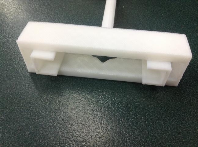
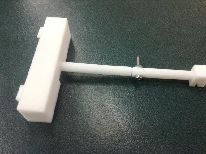
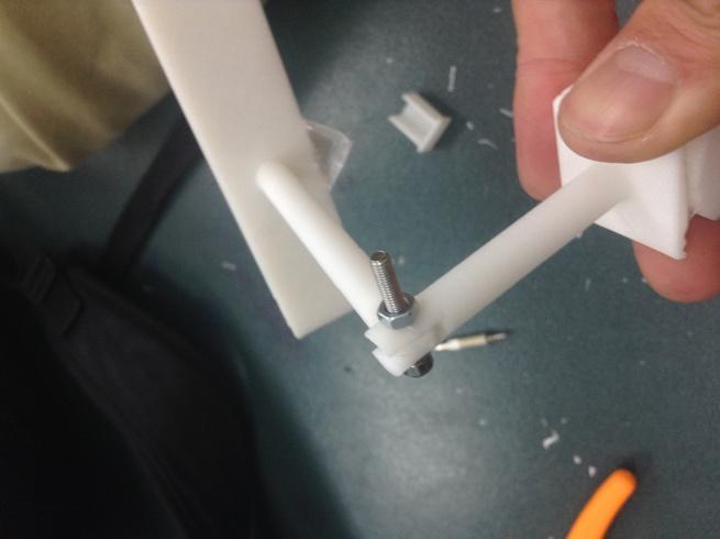
1 3.22 Finalize exact specifications of 3D printed parts. This is the part that connect between the main tube and the phone holder, it needs to be able to - Fit into the main tube perfectly - This part need to be strong enough to hold both the cell phone and the holder. - The hole on the bar need to fit with the screw given, which has the diameter of 3mm, and it needs to connect with the holder part nice and tight.
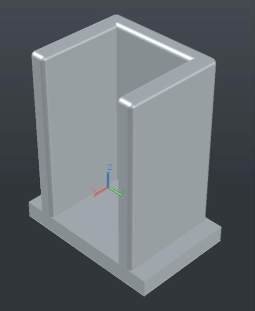
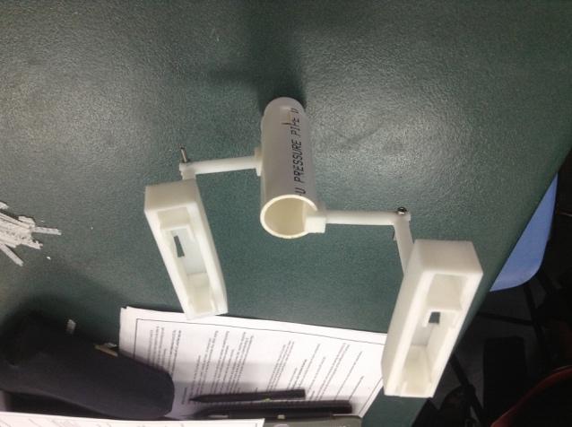
2 - The bar needs to be thick enough so that it would not run out of shape when holding a phone This is the main body of the cell phone holder, it needs to - Strong enough to hold the phone - The hole at the bottom needs to be big enough for the cable to go through - Connect with the other part nicely - Gap in the middle need to fit with the small holder piece inside this piece
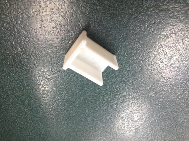
3 - The small piece on the middle needs to be able to slide from side to side This piece is the part that join with the phone holder, which is used for holding phones, it needs to - Strong enough and would not break as it is quite small - Be able to slide in the body part - Long enough to hold the phone
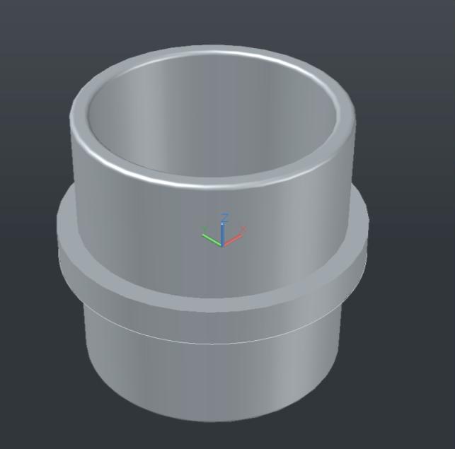
4 This is the piece that connect the main tube together, it needs to - Outside diameter need to be accurate, which is same size as the inner diameter of the tube - Strong enough so that it won't break - Hole in the middle needs to be big enough for the cables to go through
5 This piece will be putted on the top, which is designed for keeping the keys and coins in position. It needs to - The bottom part need to be fit into the main tube tight - Big enough to hold some keys and coins

6 AutoCAD Drawings Firstly, to make a start of my project, we need to open the AutoCAD, and create a new file. And then I draw the top view of the first piece, which is shown below. After that, i use the pulling tool to pull the piece into the correct length, and I used the Fillet Edge tool the make a smooth edge on my project, and the this piece becomes I kept the bottom of this part sharp because the straight angle would make it has a perfect fit with the cell phone holder part. To finish this part, I need to export this project into.stl file, to do so, I need to select the piece. After I have select the piece, I click the File button at the top left corner, and choose the Export button.


7 After that, a window will pop up, which shows the name the file would export to and the type of file you want it to be exported, in this case, I want to export this piece to.stl file. And finally, click the save button to save the exported file. For some part, it is a bit difficult when making the model in the AutoCAD, this is the piece that connect to the main tube. I need to make a hold on the middle of the head, so that I can put a screw across it to lock it tight with the phone holder. To make a hole, first I need to find out the center, so I drew 2 diagonal line and find the intersect, which is the center. Then I made a cylinder next to it with the diameter of 3mm and the length of 15mm (it just need to be longer than the diameter of the tube in the image. And I


8 shift the cylinder in to the tube just across the place where I want to remove. After that, I click and hold my mouse at the union tool, and 3 tools appears, they are the union tool, subtract tool and intersect tool. I click the subtract tool, and I select the piece that I want to save and press Enter, and select the part that I want to subtract, and press Enter again, the cylinder has disappeared and leave 2 holes and which is what I want. Before I using the Fillet Edge tool to get a smooth ending, I used the union tool to make my project into one piece so that I can use the Fillet tool correctly, (if I don t use the union tool, the pieces would be on its own, for example, in the image above,

9 the tube would be separate with the cube at the back, so when using the fillet tool, it would just get a round edge on the tube, but not the intersection. But after using the union tool, the two parts become one,) and now the Fillet tool can do the intersection.


10 The final shape of this piece becomes And here are the other pieces that I made in AutoCAD.
11


12 CNC Machine CNC Machining is a process used in the manufacturing sector that involves the use of computers to control machine tools. Tools that can be controlled in this manner include lathes, mills, routers and grinders. The CNC in CNC Machining stands for Computer Numerical Control. In modern CNC systems, end-to-end component design is highly automated using computer-aided design (CAD) and computer-aided manufacturing (CAM) programs. The programs produce a computer file that is interpreted to extract the commands needed to operate a particular machine via a post processor, and then loaded into the CNC machines for production. Since any particular component might require the use of a number of different tools drills, saws, etc., modern machines often combine multiple tools into a single "cell". In other installations, a number of different machines are used with an external controller and human or robotic operators that move the component from machine to machine. In either case, the series of steps needed to produce any part is highly automated and produces a part that closely matches the original CAD design. Here are some example of CNC machines CNC router is a computer controlled cutting machine, it can be used to cut many hard materials that hand held router can not cut, such as aluminum, steel and plastic. A CNC router typically produces consistent and high-quality work and improves factory productivity. Unlike a jig router, the CNC router can produce a oneoff as effectively as repeated identical production. Automation and precision are the key benefits of CNC router tables. By comparison, the hand held router is a tool used to rout out (hollow out) an area in the face of a relatively hard workpiece, typically of wood or plastic. The main application of routers is in woodworking, especially cabinetry. And it is not easy to do the very accurate work by using the hand held router, while using CNC router to the the fine work is easy, you just need to make the model on a computer, and transfer the
13 code to the CNC machine, then the machine would do the work for you. And here are some of the code that the CNC machine use to make the project. Code Description G00 G01 G02 Rapid positioning Linear interpolation Circular interpolation, clockwise Milling ( M ) M M M Turning ( T ) T T T Corollary info On 2- or 3-axis moves, G00 (unlike G01) traditionally does not necessarily move in a single straight line between start point and end point. It moves each axis at its max speed until its vector is achieved. Shorter vector usually finishes first (given similar axis speeds). This matters because it may yield a dog-leg or hockey-stick motion, which the programmer needs to consider depending on what obstacles are nearby, to avoid a crash. Some machines offer interpolated rapids as a feature for ease of programming (safe to assume a straight line). The most common workhorse code for feeding during a cut. The program specs the start and end points, and the control automatically calculates (interpolates) the intermediate points to pass through that will yield a straight line (hence "linear"). The control then calculates the angular velocities at which to turn the axis leadscrews via their servomotors or stepper motors. The computer performs thousands of calculations per second, and the motors react quickly to each input. Thus the actual toolpath of the machining takes place with the given feedrate on a path that is accurately linear to within very small limits. Very similar in concept to G01. Again, the control interpolates intermediate points and commands the servo- or stepper motors to rotate the amount needed for the leadscrew to translate the motion to the correct tool tip positioning. This process repeated thousands of times per minute generates the desired toolpath. In the case of G02, the interpolation generates a circle rather than a line. As
14 with G01, the actual toolpath of the machining takes place with the given feedrate on a path that accurately matches the ideal (in G02's case, a circle) to within very small limits. In fact, the interpolation is so precise (when all conditions are correct) that milling an interpolated circle can obviate operations such as drilling, and often even fine boring. Addresses for radius or arc center: G02 and G03 take either an R address (for the radius desired on the part) or IJK addresses (for the component vectors that define the vector from the arc start point to the arc center point). Cutter comp: On most controls you cannot start G41 or G42 in G02 or G03 modes. You must already have compensated in an earlier G01 block. Often a short linear lead-in movement will be programmed, merely to allow cutter compensation before the main event, the circle-cutting, begins. Full circles: When the arc start point and the arc end point are identical, a 360 arc, a full circle, will be cut. (Some older controls cannot support this because arcs cannot cross between quadrants of the cartesian system. Instead, four quarter-circle arcs are programmed back-to-back.) Corollary info M00 M01 M02 Compulsory stop Optional stop End of program M T M T Non-optional machine will always stop upon reaching M00 in the program execution. Machine will only stop at M01 if operator has pushed the optional stop button. Program ends; execution may or may not return to program top (depending on the control); may or may not reset register values. M02 was the original M T program-end code, now considered obsolete, but still supported for backward compatibility.[7] Many modern controls treat M02 as equivalent to M30.[7] See M30 for additional

15 discussion of control status upon executing M02 or M30. 3D printer is one of the CNC machine, 3D printing is any of various processes used to make a three-dimensional object. In 3D printing, additive processes are used, in which successive layers of material are laid down under computer control. These objects can be of almost any shape or geometry, and are produced from a 3D model or other electronic data source. A 3D printer is a type of industrial robot. After you plug the 3D printer to the computer, a software appears, which is called Up and you can use this software to control the 3D printer and sending the project. The project need to be export to the.stl file, and if you open the.stl file with notebook, there appears some code which the machine can read it
16 Setting up and using 3D printer Zeroing Zeroing is also called initializing, to do so, we can press the button at the front for about 3 second or if the 3D printer is connect to the computer, and we can use the software called UP to initialize it. And what it does is move the plate in XYZ axis to check the maximum distance it can go, it would just simply moves up and down, left and right, and front and back. It is a good idea to do the auto leveling if you haven't use the 3D printer for a long time or you drop the machine accidentally. To do the auto leveling, we need to plug in the black calibration cable into the auto leveling sensor and mount under the print head. So we can using the UP software to do the auto level, there is a button that you can click in computer that called auto leveling, if you click it, the plate would move up, and the nozzle would click 9 times on the plate to see if the plate is flat or not. After you do so, the computer would give you the information about it whether it is leveled or not. Also, you can check the nozzle height before printing your project, just simply click the nozzle height detect in the computer, the table will rise up and the nozzle will touch the silver switch in order to automatically set the height. Preheating table Before you start to print your project, you have to make sure that the table is heated up, the reason for it is that the plastic would stick to the table so it would not snap or lift up by accident. Heating the table would help making a more accurate model. Placing your model To place your model, first you need to connect the 3D printer to a computer, in the UP software, you click file, and then click open to open the project that you have done, the file must be in the form of.stl. After you place the model into the software, you can click auto placement, this would automatically put your project on the center, the best place that computer calculated. Also, there is a menu on the right that you can use to move, rotate or scale your project in the XYZ direction. You need to pay attention to how you want to put your project, because 3D printer is printing layer by layer, so this would affect the strength of your project, also, sometimes it might creates some supports which waste some material. Setting Sometimes you also need to change a few settings to get a better object, firstly, Z Resolution, this is the thickness of the layers, if you want a fine product, you may need to change this to as small as possible. The Fill option is about the objects internal fill, for example, if you want your object to be hard, you might need to change the fill to solid, which means there is no holes in the object. Support angle is another thing that you might opened to change, the greater the angle, the more support it will print, so the object you are printing would not go out of shape so easily. Sometimes you might need to change the
17 printing speed, to do so, change the settings in the print quality, normal means average quality, fine means good quality but takes longer to print, while fast mode would give you a draft quality but it takes less time. After you have done all these, you can click OK and start printing. Problems and issues I have had some problems when I did the prototype, when I print the phone holder part for the first time, I printed it at the wrong way, and this makes the tube very weak, and it does break right after I take the object out. Safety For safety, you need to wear gloves when you take the hot plate out, and when you want to take the rafts and support material out, you need to wear safety glasses to avoid the flying pieces.


18 Evaluate and record process After I print out all my pieces the first time, I found out some problems. For the small piece that been put into the cell phone holder, the part that will stuck into the holder is too wide, which it is designed to fit tightly inside, but the problem is I can t put it in, if I force it in to the phone holder, the phone holder would just snap. So I redesign the piece again and make it narrower, and this time, it works better, even though I need to put some force to put it in, it would not break the phone holder. For the phone holder part, same problem as above, I have made the wall thicker to increase the strength and also, I have make the gap larger for the small part to fit in. When printing, I have to lie the piece down to get a better strength on the tube as 3D printer would print stuff layer by layer. Also, I need to change the settings in the 3D printing software, make the support angle to 50 degrees to help keeping it in shape. When I Print this part for the first time, the weather was too cold, and the piece just warped as the table cools down too fast. So later on the teacher made a box to cover the whole 3D printer to keep it warm, and this makes the project been printed much better.


19 For the part that connect to the main tube, the cube was too big and it does not fit in the hole on the main tube, so I redesign the project again to make it smaller, and also make the wall on the back thicker to get a better strength so it would not break so easily ( the original one broke). I have to make the support angle to 50 degree for this part because if I don t do that, the part would go out of shape. For the part that sit on the top, it was too big, and it is too hard to get the support off after cooled down. So I redesign a smaller one, and have 4 small tubes that sticks out to hold the keys.


20 These are the final product that been printed out.
21 So far, I have meet most of the specifications of my design. But for the cell phone holder part, the charger does not go through, and we can charge our phone on the phone holder, so for farther improvement, I will redesign the cell phone part again, I would change the way that it connect to the tube, I might split it in to two branches and a hole on the middle for the cable to go through.
FUNDAMENTAL MANUFACTURING PROCESSES Computer Numerical Control
 FUNDAMENTAL MANUFACTURING PROCESSES Computer Numerical Control SCENE 1. CG: FBI warning white text centered on black to blue gradient SCENE 2. CG: disclaimer white text centered on black to blue gradient
Preface 11 Key Concept 1: Know your machine from a programmer s viewpoint 17
 Table of contents Preface 11 Prerequisites 11 Basic machining practice experience 11 Math 12 Motivation 12 Controls covered 12 What about conversational controls? 13 Controls other than Fanuc 13 Limitations
IMPORTANT INFORMATION
 IMPORTANT INFORMATION The following section is taken from the DTHCIV Setup and Config for LINUX Manual pages 97-101. The setup and testing of the DTHC IV Is CRITICAL to the success of having a working
Techniques With Motion Types
 Techniques With Motion Types In this lesson we ll look at some motion techniques that are not commonly discussed in basic CNC courses Note that we re still talking about the basic motion types rapid (G00),
Renishaw Ballbar Test - Plot Interpretation - Mills
 Haas Technical Documentation Renishaw Ballbar Test - Plot Interpretation - Mills Scan code to get the latest version of this document Translation Available This document has sample ballbar plots from machines
Intelligent Pendulum Hardness Tester BEVS 1306 User Manual
 Intelligent Pendulum Hardness Tester BEVS 1306 User Manual Please read the user manual before operation. PAGE 1 Content 1. Company Profile... 3 2. Product Introduction... 3 3. Operation Instruction...
3. Electronics and MMU2 unit assembly
 Written By: Jakub Dolezal 2018 manual.prusa3d.com/ Page 1 of 34 Step 1 Tools necessary for this chapter Please prepare tools for this chapter: 2.5mm Allen key for M3 screws 2mm Allen key for nut alignment
Short instructions for initial preparation and installation of A4xx/A6xx machines.
 Short instructions for initial preparation and installation of A4xx/A6xx machines www.accuratecnc.com Jan 19, 2014 Short instructions for initial preparation and installation of A4xx/A6xx machines....
F7000NV ROBOT VISION OPERATING MANUAL
 Rev. C Feb 2012 F7000NV ROBOT VISION OPERATING MANUAL Rev. C Feb 2012 This page has intentionally been left blank. Contents Contents Chapter 1. Getting Started... 5 1. Preface... 5 2. Manuals... 5 3. Setting
Axle Assembly Poke-Yoke
 Indiana University Purdue University Fort Wayne Opus: Research & Creativity at IPFW Manufacturing & Construction Engineering Technology and Interior Design Senior Design Projects School of Engineering,
Manual placement system MPL3100. for BGA, CSP and Fine-Pitch components
 Manual placement system MPL3100 for BGA, CSP and Fine-Pitch components Part No: MPL3100BA1.0e Issue Date: 02/2001 You have opted for an ESSEMTEC MPL3100 pick and place system. We thank you for this decision
Three Axis Digital Readout System
 NEWALL MEASUREMENT SYSTEMS C80 Three Axis Digital Readout System CONTENTS 2 SPECIFICATIONS 3 CONNECTIONS 4 MOUNTING 4 Arm Mounting (Non-adjustable) 4 Arm Mounting (Adjustable) 5 Face Mounting (Adjustable)
GE Fanuc Automation. Series 0i C CNC Family. The Best Value CNC with GE Fanuc Reliability
 GE Fanuc Automation Series 0i C CNC Family The Best Value CNC with GE Fanuc Reliability The Series 0i CNC Controller Family The new Series 0i CNC is the proud successor to the Series 0, the world s most
Setup and Start Guide for Torchmate CNC Tables
 Setup and Start Guide for Torchmate CNC Tables Revised: April 2010 1 Table of Contents Configuring the Driver Software... 3 Signal Generator Driver Setup... 3 Driver Installation for Windows Vista... 5
SHUTTLE WITH INFRA-RED DETECTION SAS2-IR
 SHUTTLE WITH INFRA-RED DETECTION SAS2-IR Shuttle Model Train Controller with Infra-Red Detection Automatically operates a train backwards and forwards along a single line. Train detection using Infra-red
BAYKAL PLASMA PRODUCT ANNOUNCEMENT
 BAYKAL PLASMA PRODUCT ANNOUNCEMENT BAYKAL PLASMA TRUE HOLE CUTTING UPGRADE With existing competitors and new competition, Baykal is following its principle of offering competitive features which add value
(Refer Slide Time: 00:55)
") Computer Numerical Control of Machine Tools and Processes Professor A Roy Choudhury Department of Mechanical Engineering Indian Institute of Technology Kharagpur Lecture 1 Introduction to Computer Control
Computer Numerical Control of Machine Tools and Processes Professor A Roy Choudhury Department of Mechanical Engineering Indian Institute of Technology Kharagpur Lecture 1 Introduction to Computer Control
Advances in Motion Control
 Haas Technical Documentation Advances in Motion Control Scan code to get the latest version of this document Translation Available INTRODUCTION Developments in hardware and software improve motion control
GEOSATpro GS120. DiSEqC 1.2 Motorized H-H H Motor
 DiSEqC 1.2 Motorized H-H H Motor GEOSATpro GS120 Compatible with DiSEqC 1.2 & USALS Receivers Adjustable Hardware Limiters for 140 Degree Coverage Goto X Preprogrammed for North American Satellites LED
DIRECT DRIVE ROTARY TABLES SRT SERIES
 DIRECT DRIVE ROTARY TABLES SRT SERIES Key features: Direct drive Large center aperture Brushless motor design Precision bearing system Integrated position feedback Built-in thermal sensors ServoRing rotary
General Specifications
 General Specifications WG41F11C Compact O Frame GS 14M04B10-20E-Z1 [Style: S1] Overview The WG41F11C Compact O frame is a space-saving frame designed for coating lines of battery electrode sheets. This
SHARP Plasma inverter cutting range
 SHARP Plasma inverter cutting range Sword edge cutting www.cemont.com The plasma expert advanced powerful all metals performance portable solutions plasma gouging maintenance high quality The plasma process
Service manual Cantano W/T
 Service manual Cantano W/T Here you will see everything that should be included in your Cantano package 2 Prerequisite: Placement and leveling of the drive 5 Setting up the motor and connecting it to the
CN Remove the scanner assembly (X476 and X576 models) and all doors/covers.
 and all doors/covers.") CN598-67045 www.hp.com/support IMPORTANT: Ensure the product firmware is upgraded to at least version 1336MR before performing this repair procedure. If the firmware upgrade cannot be completed, contact
CN598-67045 www.hp.com/support IMPORTANT: Ensure the product firmware is upgraded to at least version 1336MR before performing this repair procedure. If the firmware upgrade cannot be completed, contact
viking A New Generation of Plasma Cutting Systems
 viking A New Generation of Plasma Cutting Systems Advanced Software That s Simple to Use The Viking comes with field-proven Vulcan Cutting System Software by Quickpen to make light work of even the most
PKK PKK CHARACTERISTICS. Dimensions. Travel. Travel speed. Acceleration. Temperature. Special versions APPLICATION AREAS. PLE max.
 PKK loa d / (kg/m) PKK 10 8 6 4 2 0 0 P KK 1 20 PKK applications 49 PKK dimensions 50 PKK types 52 PKK sizes 54 PKK parts 55 PKK assembly 56 PKK article numbers 62 LOAD DIAGRAM PKK 2 2 0 2 P KK 2 40 PKK
GeChic Corporation 13F.-4, No.367, Gongyi Road, West District, Taichung City 403 Taiwan (R.O.C.) Customer Service:
 Customer Service:") GeChic Corporation 13F.-4, No.367, Gongyi Road, West District, Taichung City 403 Taiwan (R.O.C.) Customer Service: +886-4-23198080 Monitor for Laptop 1301 User Manual Table of Contents Chapter 1 Content
GeChic Corporation 13F.-4, No.367, Gongyi Road, West District, Taichung City 403 Taiwan (R.O.C.) Customer Service: +886-4-23198080 Monitor for Laptop 1301 User Manual Table of Contents Chapter 1 Content
CITOCUT Plasma inverter cutting range
 CITOCUT Plasma inverter cutting range Sword edge cutting www.oerlikon-welding.com The plasma expert advanced plasma cutting powerful all metals performance portable solutions inverter plasma gouging maintenance
MP Maker Pro Mk.1. Quick Start Guide
 MP Maker Pro Mk.1 P/N 33013 Quick Start Guide ONLINE SUPPORT Monoprice is pleased to provide free online support. For order related issues, contact the Customer Service department through the Live Chat
E X P E R I M E N T 1
 E X P E R I M E N T 1 Getting to Know Data Studio Produced by the Physics Staff at Collin College Copyright Collin College Physics Department. All Rights Reserved. University Physics, Exp 1: Getting to
Up to 85% higher Service Life due to efficient sealing method.
 Robot Accessories Feeding through Up to 85% higher Service Life due to efficient sealing method. 346 Robot Accessories Feeding through Feeding through DDF 2 Rotary Feed-through Series Size Page DDF 2 348
INSTRUCTION MANUAL COMMANDER BDH MIG
 INSTRUCTION MANUAL COMMANDER BDH MIG Valid from 0327 50173001A Version 1.0 CONTENTS INTRODUCTION... 0-1 1. PRIMARY OPERATIONAL FUNCTIONS... 1-1 Reading and setting... 1-1 Programmes... 1-2 Trigger function...
PRESTOJET Plasma inverter cutting range
 PRESTOJET Plasma inverter cutting range Sword edge cutting www.saf-fro.com The plasma expert advanced powerful all metals performance portable solutions inverter plasma gouging maintenance high quality
Incremental Rotary Encoders
 Incremental Rotary Encoders Rotary Magnetic Incremental Encoder Encoders ELTRA are designed in order to control the position and the angular speed of moving mechanical axels. Rotary Incremental Eltra encoder
DektakXT Profilometer. Standard Operating Procedure
 DektakXT Profilometer Standard Operating Procedure 1. System startup and sample loading: a. Ensure system is powered on by looking at the controller to the left of the computer.(it is an online software,
GS122-2L. About the speakers:
 Dan Leighton DL Consulting Andrea Bell GS122-2L A growing number of utilities are adapting Autodesk Utility Design (AUD) as their primary design tool for electrical utilities. You will learn the basics
Dual extruder upgrade manual addendum to assembly manual
 Dual extruder upgrade manual addendum to assembly manual This manual is intended for users that have bought the kit WITH a new printer. For user that already have their printer assembled and working, please
Transmitter Interface Program
 Transmitter Interface Program Operational Manual Version 3.0.4 1 Overview The transmitter interface software allows you to adjust configuration settings of your Max solid state transmitters. The following
TRAK TRL & ProtoTRAK LX2
 TRAK TRL & ProtoTRAK LX2 Safety, Programming, Operating and Care Manual Document: P/N 20099 Version: 052814 Southwestern Industries, Inc. 2615 Homestead Place Rancho Dominguez, CA 90220-5610 USA T 310.608.4422
GSK988T TURNING CENTER CNC SYSTEM
 GSK988T TURNING CENTER CNC SYSTEM GSK988T is a new CNC controller for slant bed CNC lathe and turning center, adopt micro processor of 400MHz high performance, and it can control five feeding axes (including
Board Production In CircuitPro
 Board Production In CircuitPro Requirements 1. Circuit Pro version 1.5 revision 164 or higher 2. Generated tool paths (Processed Gerber or DXF file) 3. 1x piece of copper material 4. 1x set of tools (combo
Setup Guide. Read me BefoRe unpacking!
 Setup Guide Read me BefoRe unpacking! Package Contents In The Replicator package The Replicator SD card (in The Replicator SD card slot) In the Accessory Box found within The Replicator frame Single or
USER MANUAL. 28" 4K Ultra HD Monitor L28TN4K
 USER MANUAL 28" 4K Ultra HD Monitor L28TN4K TABLE OF CONTENTS 1 Getting Started 2 Control Panel/ Back Panel 3 On Screen Display 4 Technical Specs 5 Care & Maintenance 6 Troubleshooting 7 Safety Info &
HCS - HES Cabling Systems
 HCS - HES Cabling Systems Installation Manual for HCS High-Capacity Fiber-Optic Rack-Mount Cabinets Be sure to read and completely understand this procedure before applying product. Be sure to select the
THE CABLE TRAY SYSTEM
 C A B L E S A N I T A T I O N C A B L E T R A Y S Y S T E M S THE CABLE TRAY SYSTEM The SILTEC cable tray system is a product, developed for optimum functionality and with focus on simplicity and accessibility,
PERFACTORY Rapid Prototyping System. Troubleshooting Guide. PERFACTORY Machine
 PERFACTORY Rapid Prototyping System Troubleshooting Guide PERFACTORY Machine Envisiontec GmbH Elbestraße 10 D-46768 Marl Germany Phone:+49 2365 915460 Email:support@envisiontec.de Disclaimer This troubleshooting
COLOUR CHANGING USB LAMP KIT
 TEACHING RESOURCES SCHEMES OF WORK DEVELOPING A SPECIFICATION COMPONENT FACTSHEETS HOW TO SOLDER GUIDE SEE AMAZING LIGHTING EFFECTS WITH THIS COLOUR CHANGING USB LAMP KIT Version 2.1 Index of Sheets TEACHING
Check what you have received against the component checklist and hardware above.
 SA46S SA46W SA46B SA46PB Component Checklist Installation Instructions SYSTEMA Systema Monitor Arm 460mm HARDWARE Display Mounting Spacers (x4) Display Mounting Screws Arm Assembly VESA monitor head M4
KRAMER ELECTRONICS LTD. USER MANUAL
 KRAMER ELECTRONICS LTD. USER MANUAL MODEL: Projection Curved Screen Blend Guide How to blend projection images on a curved screen using the Warp Generator version K-1.4 Introduction The guide describes
CITOCUT Plasma inverter cutting range
 CITOCUT Plasma inverter cutting range Sword edge cutting www.oerlikon-welding.com The plasma expert advanced powerful all metals performance portable solutions inverter plasma gouging maintenance high
Teltron Delection Tube D
 Teltron Delection Tube D 1011119 Overview The electron-beam deflection tube is intended for investigating the deflection of electron beams in electrical and magnetic fields. It can be used to estimate
SPECIFICATION NO Model 207 Automatic GTAW Welding System
 1.0 Introduction The Model 207 is a completely self-contained Gas Tungsten Arc Welding (GTAW) System requiring only input power, inert gas and AMI Welding Head (or manual torch) for operation. Its small
USER MANUAL. 27" 2K QHD LED Monitor L27HAS2K
 USER MANUAL 27" 2K QHD LED Monitor L27HAS2K TABLE OF CONTENTS 1 Getting Started 2 Control Panel/ Back Panel 3 On Screen Display 4 Technical Specs 5 Troubleshooting 6 Safety Info & FCC warning 1 GETTING
-Technical Specifications-
 Annex I to Contract 108733 NL-Petten: the delivery, installation, warranty and maintenance of one (1) X-ray computed tomography system at the JRC-IET -Technical Specifications- INTRODUCTION In the 7th
03-Durchfuehren_RZ_0708_EN.qxd:03-Durchfuehren GB.qxd :06 Uhr Seite 200 Feed-through
 Feed-through Feed-through FEED-THROUGH Series Size Page Rotary Feed-through for Robots DDF 202 DDF 031 206 DDF 040 208 DDF 040-1 210 DDF 050 212 DDF 050-1 214 DDF 063 216 DDF 080 218 DDF 080-1 220 DDF
Support Frame STB Technical Instruction Manual
 Support Frame STB Technical Instruction Manual Fig. 2.1: Support frame STB 450 Fig. 2.2: Support frame STB 300 Fig. 2.3: Brace bracket SK 150 Product Characteristics The support frames are mainly used
Linkage 3.6. User s Guide
 Linkage 3.6 User s Guide David Rector Friday, December 01, 2017 Table of Contents Table of Contents... 2 Release Notes (Recently New and Changed Stuff)... 3 Installation... 3 Running the Linkage Program...
PKK PKK CHARACTERISTICS. Dimensions. Travel. Travel speed. Acceleration. Temperature. Special versions APPLICATION AREAS. PLE max.
 loa d / (kg/m) PKK inner height / (mm) 10 8 6 4 2 0 0 118 115 80 50 30 16 7 48 7 P KK 1 20 30 PKK applications 49 PKK dimensions 50 PKK types 52 PKK sizes 54 PKK parts 55 PKK assembly 56 PKK article numbers
AUTOMATIC CUTTING PLOTTER WITH INTEGRATED CAD CAM SYSTEM
 AUTOMATIC CUTTING PLOTTER WITH INTEGRATED CAD CAM SYSTEM KOMBO SERIES WITH SEEKER SYSTEM. SIMPLICITY AT A GLANCE. A complete range of KOMBO plotters for automatic cutting and finishing specifically engineered
1000TII TURNING CNC CONTROLLER
 1000TII TURNING CNC CONTROLLER 1000TII from CNCmakers Limited, is a superior turning machine CNC system with high performance 32-bit microprocessor, new structure design and open PLC process. It is employed
What is a Fagor Turnkey Package?
 What is a Fagor Turnkey Package? A Turnkey Package is a pre-engineered CNC-Servo System. The CNC is integrated into a functional machine tool pendant and the Servo System is engineered into an electrical
ENCODER. Incremental Angle Transducer. Series A36, A58. Key-Features:
 ENCODER Incremental Angle Transducer Series A36, A58 Key-Features: Content: Technical Data A36...2 Technical Data A58...4 Elektrical Data...6 Accessories...7 Measuring Wheels...8 Order Code...9 - Incremental
Fully ly Automaticti. Motorised Satellite t TV System. User s manual REV
 REV. 1.0 Fully ly Automaticti Motorised Satellite t TV System User s manual Customer Help Line: 1300 139 255 Support Email: support@satkingpromax.com.au Website: www.satkingpromax.com.au www.satkingpromax.com.au
BeoPlay V1. BeoPlay V1 32 & 40 Vertical Table Stand. DESIGNED FOR BeoPlay V1 40 BeoPlay V1 32. AVAILABLE IN Black White
 COLLECTION 2013 BeoPlay V1 BeoPlay V1 32 & 40 Vertical Table Stand The vertical table stand for BeoPlay V1 32 and 40 is designed to make the TV screen vertical when placed on top of a piece of furniture
AUTOMATIC CUTTING PLOTTER WITH INTEGRATED CAD CAM SYSTEM
 AUTOMATIC CUTTING PLOTTER WITH INTEGRATED CAD CAM SYSTEM KOMBO SERIES WITH SEEKER SYSTEM. SIMPLICITY AT A GLANCE. MAIN CHARACTERISTICS Multi-tool head for cutting, creasing and milling materials up to
PSC300 Operation Manual
 PSC300 Operation Manual Version 9.10 General information Prior to any attempt to operate this Columbia PSC 300, operator should read and understand the complete operation of the cubing system. It is very
SETUP TIME REDUCTION FOR CNC HOBBING MACHINE IMPLEMENTING SMED AND DESIGN OF SPLIT FIXTURE
 SETUP TIME REDUCTION FOR CNC HOBBING MACHINE IMPLEMENTING SMED AND DESIGN OF SPLIT FIXTURE 1 KARAN SHARMA, 2 NAIK NITHESH, 3 ARUN PRABHU, 4 GEORGE VARGHESE 1,2,3,4 Dept. of Mechanical and Mfg. Engg, Manipal
Medium Box for Cable Termination
 FIST-MB2-T I N S T A L L A T I O N I N S T R U C T I O N Medium Box for Cable Termination Contents 1 Introduction 1.1 Product description. 2 General 2.1 Tools 2.2 Kit contents 3 Installation and pre assembling
Bionic Elephant Trunk. Assembly Instructions
 Bionic Elephant Trunk Assembly Instructions Equipment and Supplies Required items from the Bionics Kit and/or Materials Pack: 1. Tail fin (small) assembled 2 see Start Here for tail fin assembly instructions
Materials: Programming Objectives:
 Lessons Lesson 1: Basic Chassis Overview TETRIX Getting Started Guide In this lesson, users will learn how to use the elements of the TETRIX system that will be involved in building the basic chassis of
FIST-MB2-S. FIST Medium Box for Cable Splicing Only. 4 Cable installation. 1 Introduction. Contents. 2 General. 5. Fiber routing to individual trays
 FIST-MB2-S I N S T A L L A T I O N I N S T R U C T I O N FIST Medium Box for Cable Splicing Only Contents 1 Introduction 1.1 Product description 2 General 2.1 Tools 2.2 Kit contents 3 Installation and
ARC HEIGHT CONTROL (ARC VOLTAGE CONTROL) MODEL : HAC-01-A-1M
 MODEL : HAC-01-A-1M") ARC HEIGHT CONTROL (ARC VOLTAGE CONTROL) MODEL : HAC-01-A-1M 1. INTRODUCTION 1-1 Figures - It is a kind of unit to keep up Arc height between work-piece and torch by controlling the voltage of arc; if
ARC HEIGHT CONTROL (ARC VOLTAGE CONTROL) MODEL : HAC-01-A-1M 1. INTRODUCTION 1-1 Figures - It is a kind of unit to keep up Arc height between work-piece and torch by controlling the voltage of arc; if
LM-TV09-4K2K. 4K video wall controller. User. Manual
 LM-TV09-4K2K 4K video wall controller User Manual Catalog 1.Installation Instructions 1 2.Product Brief 2 3.Controller Installed 3 4.Remote Control Settings 6 5.Pressing Setting 7 6.Specifications 7 1
TRAK TRL 1840 CSS & ProtoTRAK LX3
 TRAK TRL 1840 CSS & ProtoTRAK LX3 Programming, Operating & Care Manual Document: P/N 21210 Version: 030700 SOUTHWESTERN INDUSTRIES, INC. P. O. Box 9066 Plant location: 2615 Homestead Place Rancho Dominguez,
Commissioning Guide. firepickdelta. Commissioning Guide. Written By: Neil Jansen firepickdelta.dozuki.com Page 1 of 22
 firepickdelta Commissioning Guide Written By: Neil Jansen 2017 firepickdelta.dozuki.com Page 1 of 22 Step 1 Pre-Requisites Before commissioning, please make sure ALL of the following steps have been completed,
E4200 Antenna Installation Instructions: 1. Soldering required (here is the list of tools you will need)
") Thank you for purchasing the 6 Antenna Mod Kit for your Linksys router. First we will show you how to install the antennas for your router. Next we will teach you how to setup the DD-WRT firmware which
Thank you for purchasing the 6 Antenna Mod Kit for your Linksys router. First we will show you how to install the antennas for your router. Next we will teach you how to setup the DD-WRT firmware which
Lynx Broadband Installation Manual for Residential Packages with a 35 db Amp Quick Start Guide (first 3 pages)
") Lynx Broadband Installation Manual for Residential Packages with a 35 db Amp Quick Start Guide (first 3 pages) 1. Be sure that your kit includes all the parts shown in the Check the Equipment section in
Lynx Broadband Installation Manual for Residential Packages with a 35 db Amp Quick Start Guide (first 3 pages) 1. Be sure that your kit includes all the parts shown in the Check the Equipment section in
SCANNER TUNING TUTORIAL Author: Adam Burns
 SCANNER TUNING TUTORIAL Author: Adam Burns Let me say first of all that nearly all the techniques mentioned in this tutorial were gleaned from watching (and listening) to Bill Benner (president of Pangolin
Instruction Manual Fixed Speed Vortex Mixer Analog Vortex Mixer Digital Vortex Mixer Pulsing Vortex Mixer
 Instruction Manual Fixed Speed Vortex Mixer Analog Vortex Mixer Digital Vortex Mixer Pulsing Vortex Mixer Table of Contents Package Contents............ 1 Warranty............ 1 Installation............
AP-40. AP-40 Series Features Industry s smallest-sensor head Ultra lightweight High-speed response Two-color LED digital pressure display
 AP-34 Separate Amplifier Type Sensor Series Features Industry s smallest-sensor head Ultra lightweight High-speed response Two-color LED digital pressure display Description Industry's smallest & lightest
CNC Plasma Cutting Systems
 CNC Plasma Cutting Systems Make Money Easy to Use Improve Production times Scan to watch in Action! Finance Available! Index 1. Introduction 3. DesignEdge Software 4. Benefits 5. Nesting Feature 6. Digital
TOMELLERI ENGINEERING MEASURING SYSTEMS. TUBO Version 7.2 Software Manual rev.0
 TOMELLERI ENGINEERING MEASURING SYSTEMS TUBO Version 7.2 Software Manual rev.0 Index 1. Overview... 3 2. Basic information... 4 2.1. Main window / Diagnosis... 5 2.2. Settings Window... 6 2.3. Serial transmission
THE AMBER COMPUTER VDU PROJECT.
 THE AMBER COMPUTER VDU PROJECT. H. Holden. April. 2019. BACKGROUND: Of the vintage small cathode ray tube VDU s or video monitors, the one that has impressed me the most, is the one manufactured by Zenith
Structural Diagnostics, Inc. Leaders In Automated Ultrasonic Testing. Immersion Tanks Large Gantries Custom Systems
 sdi Structural Diagnostics, Inc. sdi Leaders In Automated Ultrasonic Testing Immersion Tanks Large Gantries Custom Systems SDI-MasterScan Motion Control and WinScan Analysis The SDI MasterScan/WinScan
Revision 1.2d
 Specifications subject to change without notice 0 of 16 Universal Encoder Checker Universal Encoder Checker...1 Description...2 Components...2 Encoder Checker and Adapter Connections...2 Warning: High
SPECIFICATION NO NOTE
 NOTE The Model 207-1 is a special version of the standard M-207 Power Supply. It has been altered for a special applications requiring low current operation at high arc voltages in ambient and pressurized
ArcPro Mach4 Plasma Screen User Guide
 ArcPro Mach4 Plasma Screen User Guide Document Revision 1.10 (Updated June 13, 2017) 2017 Vital Systems Inc. Phoenix, AZ USA For more information please visit the product web page: http://www.vitalsystem.com/arcpro
2.810 Manufacturing Processes and Systems Quiz #2. November 15, minutes
 2.810 Manufacturing Processes and Systems Quiz #2 November 15, 2017 90 minutes Open book, open notes, calculators, computers with internet off. Please present your work clearly and state all assumptions.
Installing a Wire Mesh Pulling Grip on All-Dielectric DX Armored Fiber Optic Cables
 revision history Issue Date Reason for Change Related literature SRP-004-136 Accessing All-Dielectric DX Armored Fiber Optic Cables Admonishments 1. General This procedure provides instructions for installing
USER MANUAL. 27 Full HD Widescreen LED Monitor L270E
 USER MANUAL 27 Full HD Widescreen LED Monitor L270E TABLE OF CONTENTS 1 Getting Started 2 Control Panel/ Back Panel 3 On Screen Display 4 Technical Specs 5 Care & Maintenance 6 Troubleshooting 7 Safety
iphone 7 Plus LCD Screen and Digitizer Replacement
 iphone 7 Plus LCD Screen and Digitizer Replacement Replace just the bare front panel not including the home/touch ID sensor, front-facing camera and sensor cable, or earpiece speaker in an iphone 7 Plus.
INSTALLATION INSTRUCTIONS
 INSTALLATION INSTRUCTIONS PARTS REQUIRED Parts in the box Single monitor Dual monitor M2 M8 M/Flex + (package contents will depend on configuration ordered) Tools required for installation 6.0 mm Hex Key
MiniXtend Cable with Binderless* FastAccess Technology Jacket and Buffer Tube Removal Procedures. 1. General. 2. Precautions
 MiniXtend Cable with Binderless* FastAccess Technology Jacket and Buffer Tube Removal Procedures 004-273-AEN, Issue 2 Table of Contents 1. General.... 1 2. Precautions.... 1 2.1 Cable Handling Precautions...
Figure 2: components reduce board area by 57% over 0201 components, which themselves reduced board area by 66% over 0402 types (source Murata).
.") 01005 production goes industry wide Satoshi Kataoka, Production Manager, Assembléon Asia Pacific Region and Eric Klaver, Commercial Product Manager, Assembléon, The Netherlands The introduction of the
01005 production goes industry wide Satoshi Kataoka, Production Manager, Assembléon Asia Pacific Region and Eric Klaver, Commercial Product Manager, Assembléon, The Netherlands The introduction of the
imac Intel 20" EMC 2133 and 2210 LCD Backlights (CCFL) Replacement
 Replacement") imac Intel 20" EMC 2133 and 2210 LCD Backlights (CCFL) Replacement The CCFL back lights are replaceable. I have pulled mine apart and documented my method. '''NOTE''' This is not for the feint hearted!
imac Intel 20" EMC 2133 and 2210 LCD Backlights (CCFL) Replacement The CCFL back lights are replaceable. I have pulled mine apart and documented my method. '''NOTE''' This is not for the feint hearted!
Getting started with
 Getting started with Electricity consumption monitoring single phase for homes and some smaller light commercial premises OVERVIEW: The OWL Intuition-e electricity monitoring system comprises of three
Simple and highly effective technology to communicate your brand s distinctive character
 . . . Advantages 4 Simple and highly effective technology to communicate your brand s distinctive character COST EFFECTIVE No need to print graphics, you can change your message every day! No media player
WaterVue TV Installation & User Manual
 WaterVue TV Installation & User Manual 19 Waterproof TV Dimensions of TV Front screen 486mm x 340mm x 3mm Mounting Plate 467mm x 324mm x 48mm 24 Waterproof TV Dimensions of TV Front screen 576mm x 395mm
ipad mini 4 LTE Right Cellular Antenna Replacement
 ipad mini 4 LTE Right Cellular Antenna Replacement Replace the right cellular antenna in an ipad mini 4 LTE. Written By: Evan Noronha ifixit CC BY-NC-SA www.ifixit.com Page 1 of 22 INTRODUCTION Follow
Assembling and Mounting the Presentation Display, Speakers, Speaker Screens, and Table Door
 CHAPTER 8 Assembling and Mounting the Presentation Display, Speakers, Speaker Screens, and Table Door July 13, 2012, This document provides you with the procedures you perform to assemble and mount the