A History of the Analog Cathode Ray Oscilloscope
|
|
|
- Clyde Wood
- 5 years ago
- Views:
Transcription
1 1 A History of the Analog Cathode Ray Oscilloscope by OLIVER DALTON and LIONEL KREPS
2 CONTENTS 1.Introduction 3 Cathode Ray Oscilloscope definition 3 A History of the Cathode Ray Oscilloscope 3 2 Chapter Ferdinand Braun 5 Zenneck 6 first high speed cathode ray tube 7 Lissajous' figures 8 Chapter Gas Focused Tube 9 Time Bases 10 The Burt Oscilloscope 10 Chapter Disadvantages to Gas focused tubes 11 Allen B. Dumont 13 A. C. Cossor 13 Phillips 14 Puckle 14 Voltage calibration 14 Time measurement 14 Alan Blumlein 14 Long-tailed pair 15 Miller Integrator 15 CHAPTER Improvements made between 1945 and Howard Vollum 17 Vertical Input Circuits and Probes 18 Amplifiers 18 Signal Delay 19 Horizontal System 19 Sweep Generator 20 Delayed Sweep 20 Z-Axis Amplifier 20 Cathode Ray Tubes 21 Calibrator 21 Power Supplies 21 Dual-Trace versus Dual-Beam 22 The Plug-in Concept 22 CHAPTER User Needs 24 Vertical Amplifiers 25 Horizontal Systems 26 Cathode Ray Tubes 28 Portable Oscilloscopes 28 Low Priced Oscilloscopes 29 Special Purpose Oscilloscopes 29 Storage Oscilloscopes 29 Sampling Oscilloscopes 31 High Speed Single Transient Reading Oscilloscopes 31 Offshoots 32 Competition in the Industry 33
3 3 A History of the Analog Cathode Ray Oscilloscope 1.Introduction The oldest measurement made was probably that of time. In earliest antiquity the sun dial was used to split the day into known increments but the best known early instrument capable of both night and day operation was the water clock used by the Greeks, Romans, Babylonians and Egyptians. This was a simple system consisting of a graduated measuring jar, in or out of which, water dripped at a pre determined rate. In the cathode ray oscilloscope of today the water jar has been replaced with an electrical "jar" or capacitor in or out of which, electric charge drips at a known rate. Hence our method of measurement remains essentially the same, although the time increments are now much smaller and the measurement accuracy has been significantly improved. The Cathode Ray Oscilloscope is an electronic instrument used to measure waveforms in electric circuits. It employs a narrow beam of electrons focused onto a fluorescent screen, producing a luminous graph that shows the relationships between two or more voltages. Because almost any physical phenomenon can be converted into a corresponding electric voltage, the oscilloscope is a versatile tool and is used in all forms of physical investigation. The central component in this device is the cathode ray tube, which consists of an evacuated glass container with a fluorescent screen at one end (similar to a television screen) and a focused electron gun and deflection system at the other. When the electron beam emerges from the electron gun, it passes through pairs of metal plates mounted in such a way that they deflect the beam horizontally and vertically to produce a luminous pattern on the screen. The screen image is a visual representation of the voltages applied to the deflector plates. Thus almost any graph can be can be plotted on the screen by generating horizontal and vertical voltages proportional to the lengths, velocities or other quantities to be studied. For the purpose of this article the Cathode Ray Oscilloscope will be described as an electronic instrument that displays changing electrical events (signals) as a function of time on the cathode ray tube (CRT) screen. The display is a graph, usually represented in Cartesian coordinates, with the horizontal (x axis) representing time and the vertical (y axis) the input voltage. As with any definition there are difficulties; for instance oscilloscopes are sometimes used with a second signal, not time, on the x axis but time is used in the vast majority of applications. In addition, recent developments mean that we will have to leave out the term 'Cathode Ray' in the future in order to cover oscilloscopes that digitize the incoming signal and then provide an 'oscilloscope type' display on a device other than a cathode ray tube. For instance, a digitizing oscilloscope may use a liquid crystal flat panel display. This history covers the development of analog cathode ray oscilloscopes only and ends in 1980 by which time digitizing oscilloscopes were replacing analog types to a significant extent. It is probable that analog oscilloscopes will become obsolete by the end of the 20th century. It could be argued that many of our modern electronic instruments originated as offshoots from the oscilloscope but that does not mean that they should be classified as a sub-set of oscilloscopes. Many of these instruments, such as Spectrum Analyzers, Logic Analyzers and Medical monitors will be mentioned when historically appropriate but their evolution will not be described. In the engineering and scientific areas of electrical measurements the oscilloscope probably has more applications than any other single instrument. The history of the oscilloscope perhaps illustrates better than that of any other kind of instrument, the interdependence between progress in an industry and the improvements in the instruments used by that industry.
4 One indication of its popularity is in its sales volume. For instance 1987 world sales of oscilloscopes were about $1.023B which easily exceeds that of the next ranking instrument type, the digital voltmeter, the sales of which were $467M for the same period. The incredible progress in electronics which we have seen during this century could not have occurred if it were not for the simultaneous advances made in the capabilities of the oscilloscope. It is also apparent that the oscilloscope will remain extremely important to both engineers and scientists for a long time to come. However the oscilloscope's pre-eminence is probably temporary and one can already see it losing ground to competitive types of product better suited to the rapidly expanding world of digital electronics Starting the History. We have elected to divide the history into five periods; to Scientific curiosity. Development of the cathode ray tube. No serious applications and no commercial instruments to The first complete oscilloscopes appear to Oscilloscopes start to proliferate due to the development of TV, Radar, and other pulse technologies. Requirements are for greater bandwidth and some measurement accuracy. The oscilloscope comes of age to Oscilloscopes become measuring instruments with great improvements in bandwidth, accuracy and ease of use. The foundation for the modern oscilloscope is laid to Continued advances in performance. The rise of oscilloscopes designed for somewhat specialized applications. Semiconductors have a great effect on the design of 'scopes. Several offshoots occur and many useful accessories are developed. Electro-mechanical oscillographs and cathode ray oscilloscopes were developed over much the same period of time. Both are used to measure electrical waveforms but the limitations inherent in the design of electromechanical oscillographs have considerably limited their use, and their history is not included here. An excellent reference on the history of electro-mechanical oscillographs is "Waveforms, A history of early Oscillography" [1.0]. In this book Dr. Phillips discusses in detail the construction and uses of mirror planes, contact methods, and moving coil and moving iron oscillographs.
5 5 Chapter The period coincided with the building of high voltage transmission lines, the electrification of cities, development of the telephone network and the start of wireless telegraphy. The cathode ray tube progressed from an interesting gas discharge phenomenon to a viable display tube. During this time, the Oscillograph, as the discharge tube became known, was used only by skilled engineers and experimenters having facilities capable of developing the necessary power supplies and sweep circuits. Detailed accounts of the development of the CRT during this period are contained in references [1.1] & [1.2] During the first half of the nineteenth century the experimental work of Galvani and Volta, Oersted and Ampere, Ohm and Faraday, Lenz and Henry, Gauss, Joule and Maxwell had led to the development of batteries and generators and these were rapidly becoming available as convenient sources of electricity. Also the effects of an electric discharge in a rarefied gas were well known. For almost 200 years experiments had been performed to view the changing patterns of color and light observed in exhausted globes and tubes and by the latter half of the nineteenth century several investigators were concerned with the phenomena that resulted when a high voltage was applied to an evacuated glass tube containing two electrodes. The luminescence of the resulting gas discharge had become the subject of much research fig 1.1. John Hittorf [1.3], had noted that the cathode was the source of the these "rays of glow" and that the rays diverged in all directions, travelled in straight lines and caused the glass to fluoresce when impacted by the rays. Crookes [1.4] demonstrated that the path of the rays were affected by an electromagnet and that the deflection of the path was proportional to the strength of the magnet. By improving the vacuum in the discharge tube the luminance of the discharge was reduced and he was better able to study the path of the cathode rays. He proposed that these cathode rays were actually electrified gas molecules projected from the cathode with high velocities and that the luminance of the glass was caused by the impact of the molecules upon it. This luminance was dependant on the nature of the material that the gas molecules struck. Goldstein [1.5], in 1886 was responsible for the term "Kathodoenstrahlen" or cathode rays and Perrin in 1895 [1.6] demonstrated that these cathode rays were negatively charged. During this time the central generating stations were being built and providing electric power to cities. By the end of the nineteenth century the newer generators were supplying alternating current. Monitoring the AC output of the generators was difficult, particularly at the higher frequencies that were becoming of interest. Special types of alternator were being used at frequencies of 5 & 10 khz and still higher frequencies were generated by the oscillatory circuits coming into use with the new art of wireless telegraphy. In 1896 Ferdinand Braun was the first person to conceive of the possibility of using the discharge tube as a visual indicator of the oscillatory and transient phenomenon in electrical circuits. A cathode ray tube! He understood the design requirements for such a visual indicator. If the divergent rays from the cathode could be constricted to a narrow beam, and if a fluorescent target were placed at the end of the tube as a viewing surface, then the impact of the cathode rays would produce a spot of light on the target instead of a broad luminosity across the whole tube face. Because it is possible to deflect the rays with a magnetic field, the spot could then be made to oscillate in synchronism with the varying field and the motion of the spot would reflect changes in voltage or current. Braun's tube is shown in fig 1.2. A flat disk cold cathode was the source of cathode rays and a wire in the side of the tube acted as the anode. The cathode ray beam then passed through a circular diaphragm with a small hole in its center, the hole being used to constrict the divergent cathode ray stream into a narrow
6 diameter beam. A fluorescent target consisting of a circle of mica coated with Willemite (zinc sulphide) on its inner surface was mounted at the end of the tube which contained air at low pressure. A spot of light was created at the point of impact of the cathode ray beam with the target. In his original experiment reported in 1897, [1.7], a solenoid was placed perpendicular to the tube axis outside the neck of the tube and close to the diaphragm. Connecting the solenoid to the current being studied elongated the spot into a line. The required high voltage of about 50 kv needed to produce the discharge in the residual gas in the tube was provided by a hand cranked electrostatic voltage generator. To complete the two dimensional graph he used a rotating mirror in front of the screen to provide a deflection at right angles. The waveform of the electrical supply provided by the central Strasbourg power station (120 volts at 50 Hz) was revealed as a faint, flickering, sine wave. Braun not only conceived the idea of using the discharge tube as a visual indicator, but he also introduced the cyclographic method of using the tube; providing a means of showing stationary patterns on the fluorescent screen by the simultaneous application of two right-angled deflections. In that same year, J.J. Thomson in England & W. Kauffmann in Germany each independently using a tube [1.8] similar to the Braun tube, determined that cathode rays have mass. This marked the discovery of the electron and Thomson's experiments led to the calculation of the charge to mass ratio e/m; where e is the charge on the electron and m its mass. The cathode ray beam was now known to consist of large quantities of electrons which are minute particles of negative charge, all travelling in essentially the same direction. In J.J. Thomson's tube, fig 1.3, deflector plates were used for the first time to deflect the beam. Also the fluorescent screen was coated on the end of the bulb instead of being mounted on a plate fixed inside the tube. In Kaufmann's tube electrostatic deflection and electromagnetic focusing were used simultaneously. In 1899 Zenneck simplified the Braun tube display by replacing the rotating mirror used to provide the time base. He developed an electrical horizontal scanning system that swept the electron beam across the screen at a uniform rate and then returned it to the extreme left at the end of every cycle, fig 1.4. He used an electric motor to drive a wheel with a wire fixed to its periphery. Two slip rings attached to the wire were connected via brushes to a battery, the entire arrangement resembling a modern rotary potentiometer. In this way a linear sawtooth current flowed in the solenoid and produced the linear scan as in the manner of to-day's instruments [1.9]. These early tubes were of simple structure, but because the cathode was unheated a potential of kv was required to obtain sufficient emission. The non-constant high voltage caused unstable operation and the beam was unfocussed. Because a soft vacuum was used, ions, originating from the gas molecules that were struck by electrons, bombarded the cathode and significantly shortened its life to a few tens of hours. Over the next few years there were a number of improvements to make the tube more convenient and reliable. Wehnelt made two vitally important discoveries, that a cathode emitted a greater number of electrons if heated, and that it emitted even more if the heated surface was coated with certain rare earth salts. In 1905 he introduced a hot cathode, fig 1.5, using a lime coated filament, a strong emitter of electrons which reduced the required discharge potential from kv to 1-10 kv. It was even possible to operate with a potential below 1000 volts. This was an outstanding development in that the use of a much lower voltage made the entire tube and equipment more portable and significantly increased the deflection sensitivity. However the short life of the Wehnelt cathode due to ionization, still restricted the use of the Cathode Ray Tube. 6
7 7 In 1911 Roschansky [1.10] used two pairs of deflector plates, for horizontal and vertical deflection, and mounted them inside the tube, bringing out side connections in the manner familiar to us to-day. He also used an electromagnet to focus the electron beam fig 1.6. The Braun tube, as it had become known, suffered from low photographic sensitivity, very short cathode life and difficulty of cathode replacement. As permanent records were made using a camera it was necessary that rapid phenomena be repetitive to obtain enough exposure time. In 1914, Dufour constructed what may be called the first high speed cathode ray tube [1.11]. He used a glass discharge tube into which the cathode and anode were sealed, fig 1.7, a glass deflection chamber onto which the discharge tube was fitted using a ground conical joint, and then a metal photographic chamber. Due to the use of a soft vacuum, as the beam passed between the deflector plates it ionized the residual gas, making the space between the deflectors conductive and impairing the accuracy of deflection. Dufour avoided this difficulty by fitting the deflection plates outside the vacuum tube. The photographic plates were mounted in the photographic chamber inside the vacuum so that the beam impinged directly on to the sensitized surface, greatly increasing the recording efficiency. He also increased the accelerating voltage up to 60kV as compared to the 10kV more usual with the sealed Braun tube. The inclusion of the photographic plate in the vacuum chamber required a means for inserting and removing the plates and for pumps to produce and maintain the vacuum. Also having continuous evacuation pumps permitted the oscillograph to be constructed of metal instead of glass, which had the advantage of complete electrostatic shielding and of enabling a more accurate and robust apparatus to be produced. The Dufour tube was designed to investigate the transients occurring on power transmission lines due to lightning surges so it was always used in a single sweep mode and required a very high brightness. The cold cathode tube typically operated at kv with a discharge current of about 1mA. The deflection sensitivities were of the order of 100 volts/cm. and it was capable of photographic writing speeds of 0.3 cm/µs. For recording low frequencies he used film on a conventional revolving drum and photographic plates for high frequency transients. A major problem was fogging due to the film being hit by stray electrons while waiting for the transient to occur. Dufour significantly reduced this problem by only exciting the cathode during the time of recording. A circuit [1.12] for achieving this due to the General Electric Co, is shown in fig 1.8. Capacitors C are charged through R to the peak rectifier voltage and the three electrode sphere gap XYZ set so the two gaps in series will not break down due to the voltage between X and Z. A fraction of the surge voltage between the transmission line and earth is applied between the electrode Y and earth. Depending somewhat on its polarity, Y will spark over to X or Z causing the other gap to break down effectively shorting X and Z. The two capacitors C are then in parallel with both R and the discharge tube so the beam will be initiated at twice the peak rectifier voltage and the time sweep will be started by charging Ct through Rt. A second divider B applies the surge voltage to the deflector plates via a coupling capacitor. The length of transmission line between A & B is chosen so that the arrival of the signal surge voltage is delayed until the discharge is steady and the sweep has achieved the correct velocity for starting the trace. By 1922 Dufour had made improvements to his original tube. Using a harder vacuum and a pre-anode focus coil to reduce the beam width, he achieved a photographic writing speed in excess of 3000 cm/µs. See fig 1.9.
8 During these years, the horizontal time base scan was generated using waveforms of known shape, usually a sine wave for horizontal deflection. The patterns formed when two varying voltages are applied to the two sets of deflection plates are known as Lissajous' figures, and the type of pattern displayed allows for frequency comparison. The unknown waveform provided the vertical deflection and the sine wave the horizontal deflection. The required wave shape was then calculated from the displayed loop. In most instances the reference sine wave was derived from the power line supply but by using other frequencies the Lissajous loop method could be used to deduce the unknown waveform. References [1.13] and [2.4] provide detailed descriptions of the methods of displaying and interpreting Lissajous displays. A sinusoidal timing wave produces a deflection proportional to sin(ωt), and so is a non-linear function of time. However this disadvantage can be overcome by using the center portion of the wave (the part between a and a in fig 1.10) as the departure from linearity is only about 2.5%. Fleming [1.14] among others, used a very large scan such that during the time the spot was moving across the small screen it was virtually linear. This technique together with the Lissajous method were used almost exclusively by oscillograph users. 8
9 Chapter Until 1920 the use of the oscillograph was restricted due to the short life of the Wehnelt cathode, the difficulties of producing a well focused spot and centering the electron beam. In 1922 Van der Bijl described the phenomenon of gas focusing of a slow electron beam and Johnson designed the first, practical low voltage, gas focused, long-life cathode ray tube, the Western Electric model 224, [2.1]. The use of gas focusing eliminated the need for a focusing electromagnet. The operating principle of a gas focused tube is as follows: The tube is filled with a small quantity of inert gas and electrons are emitted from the cathode as a divergent stream. The electrons, which are fast moving particles, would continue to diverge but they impact the gas molecules. These are some thousands of times more massive and are designed to be sufficiently numerous to ensure that the electrons can travel only small distances before hitting a molecule. Upon impact an electron is ejected from the gas molecule which is therefore left with a positive charge. The overall result is that a column of positive ionization develops down the length of the beam and builds up a positive space charge within the beam. This will tend to neutralize the negative space charge due to the electrons and cause the beam to converge towards the center, the magnitude of the convergence depending on the degree of ionization. The conditions for focus will therefore involve the type of gas and gas pressure, and the electron velocity and tube length. If the amount of ionization can be controlled the degree of convergence or focus will be controlled and this was achieved by altering the rate of emission of electrons from the heated cathode. A variable resistance was inserted in the cathode heating circuit so that increasing the filament current increased the electron emission and the degree of positive ionization. The field around the beam therefore increased and the electrons were brought to a focus in a shorter distance. An operating voltage of 300 volts was the design parameter, and a thermionic filament cathode was used. Because there is some ionization of the gas in the cathode to anode path and the filament exposure to the ion bombardment would reduce the life severely, the filament was wound in the form of a helix and mounted coaxially with the anode and the perforation in the anode disc. In this way it was out of the direct path of the ions and the filament life was extended to around hundred hours, orders of magnitude better than the Braun tube. The electron gun and the complete tube are shown in fig 2.1 The design concept was very simple, in that the filament, anode, and two pairs of deflecting plates were carried on a simple mounting at one end of the tube and a phosphorescent screen formed the other end. Gas focusing produced a well shaped spot and the entire cathode ray tube was constructed and sealed at the factory and sold as a complete unit. However when the cathode was worn out a new tube had to be purchased. A simplified version of the Dufour tube was first proposed by J.J.Thomson and developed to a commercial form in 1923 by Wood [2.2]. It used a heated filament with a cathode to anode potential of 3000 volts and a hard vacuum. Since there is no gas for the electron beam to ionize as it passes through the deflection system, the deflector plates were mounted inside the tube, fixed in position and connected by terminals to the outside. Fig 2.2 shows the construction and sample of a tube. With this design, the photographic speed was still very high and the serviceability excellent, in that a burnt out or defective filament could be unscrewed from the filament holder and a new one fitted very quickly. After deflection the beam impacted the door of the photographic chamber. This was coated on one side with a phosphorescent material and viewed through a window in front of the tube body. When a photographic record was required the door was rotated out of the way and the photographic plate exposed. It was possible to produce the desired vacuum from atmospheric pressure in about 15 minutes so the entire unit was very adaptable.
10 By the early 1920s the user had available three different types of cathode ray tube: the high voltage Dufour tube, the "medium" voltage Wood tube and the low voltage Johnson design. From the point of view of low cost, convenience and ease of use, the Western Electric tube was the obvious choice but for single sweep recording the other two were needed. 10 Time Bases As previously described, the first linear time base sweep was a mechanical system used by Zenneck in In 1920, Rogowski [2.3] devised an electrical method. He used a constant current to charge and discharge a capacitor. Two opposed diodes working in their saturation region provided the constant current and this produced a triangular waveform. The supply potential was required to be very much higher than the diode saturation voltage and to make the retrace time faster than the forward sweep he used unequal heating of the two diode filaments. By making the discharge diode work at a higher current the discharge time was faster as shown in fig 2.3. In 1924 Kipping [2.4] used a neon filled glow discharge lamp to charge and discharge a capacitor. The voltage difference between the striking and extinction potentials of the discharge tube produced a large amplitude sawtooth voltage, and for many years the gas filled discharge tube was used in this manner to provide the timebase sweep. One of the first circuits to have a very wide range of sweep speeds was due to Watson-Watt in 1923 [2.5]. Called a "squegger" or "ticking grid oscillator", it consisted of an RF oscillator, with a frequency range of 2-5 MHz and having an R-C time constant in the grid circuit shown in fig 2.4. The duration of the burst oscillation constituted the charging period for the capacitor. This is very much less than the long discharge time constant CR which constituted the sweep period. Replacing the resistor with a diode operating at constant current improved the linearity and the circuit had a range of linear sweeps from 1Hz to 50kHz. A very complete description of the development of time base circuits from this time until the end of 1945 is given by O.S. Puckle [2.6]. Because the cathode ray tube was inertialess and hence superior to other measurement devices, the oscillograph, as it was then known, was used by specialists such as engineers engaged in electrical power and telephone systems. Considerable skill was required to use them, their operating life was short and laboratory facilities were usually required to provide the necessary ancillary equipment. The first description known to the authors of what could be called a typical modern oscilloscope was described by Bedell & Reich in 1927, ref [2.7]. Manufactured by the H.C. Burt Co. this first ever commercial product, fig 2.5, had a number of features not previously described in the literature. As stated by its designers, "it was intended to show variations in a number of quantities at the same time and also to display them as curves, with time as the abscissa using rectangular coordinates in the manner in which everyone is familiar". As it was primarily intended for visual observation it was given the name "Oscilloscope" and this was the first time that this designation had been used. The oscilloscope used the low voltage Western Electric tube designed by Johnson and had a motor driven four way distributor to which four input signals were connected. The distributor is shown in fig 2.6. A brush B, bears on a continuous slip ring to which are connected staggered quadrants. Each of the four remaining brushes comes in contact, in turn, with one of the quadrants. The output terminals Yo & Y are connected to the oscilloscope deflector plates via an optional amplifier.
11 Terminals Y1-Y4 are connected to the circuits under test and a zero line is obtained by shorting Yo to one of the input terminals. The traces can be displaced from one another by connecting a battery in series with the signal and the common terminal Yo. The timebase consisted of a capacitor charged via a vacuum tube operated in the constant current mode and discharged by a neon tube. Synchronization of the oscillating timebase circuit was achieved by introducing a small amount of the signal under observation and Fig 2.7 shows the resulting stabilized display. About this time engineers had begun to realize that to properly characterize their equipment they could not just use steady state operation but had to observe transient response as well. Also by about 1930 electronic television systems were being discussed as experimenters turned from mechanical to electronic scanning. The problems associated with synchronizing and scanning circuits made a good oscilloscope a necessity. The signals needing to be studied were transient in nature, occurring at frequencies of a few kilo-hertz so ruling out all mechanical instruments. As the Oscilloscopes currently in existence were too bulky, too dim or too insensitive to be useful, television engineers were forced to develop their own instrumentation with which to develop the new television technology. So for the next few years oscilloscope development closely followed the development needs of high quality Television. An interesting reported statistic was that in 1930, Bell Labs had over 100 mechanical oscillographs in use. Chapter By 1930 there were several different models of oscilloscopes in use. However they all used the low voltage (300 volt), gas focused tube with a simple synchronous timebase and very little in the way of vertical amplification. What there was consisted of a single A.C. coupled amplifier that could be cascaded with another into two stages of amplification. The first big change came with a cathode ray tube design by Von Ardenne [3.1] that operated over a voltage range from 300 to 3500 volts and provided a tremendous increase in trace intensity. To achieve sufficient brightness the entire beam was required to pass through the anode aperture and this was achieved by focusing the beam electrostatically. He made the Wehnelt cylinder surround the cathode and be co-axial with the path of the beam down the tube, fig 3.1. By operating the cylinder at a sufficiently negative potential with respect to the cathode and by careful design of the cathode itself, the lines of force focused the beam sufficiently well so that nearly all the electrons passed through the 2mm aperture in the anode disc. A higher vacuum was used and traces of inert gas introduced to just provide the fine focus at the screen in the manner previously described. This method of using the Wehnelt cylinder or grid as it later became known, (actually a misnomer as it is not in fact a grid), had two major advantages, first it provided a convenient focusing control and second it reduced the disastrous ionic bombardment of the filament that was responsible for the short cathode life. The CRT operated satisfactorily at any voltage from 300 to 3500, and the steepness of the luminosity/electron velocity characteristic of most fluorescent screens over this range of voltage made possible daylight viewing of the screen and external photography at substantial recording speeds. The increase in accelerating voltage from 300 to 2000 volts (the usual operating condition) provided a nearly fifty fold improvement in intensity at the expense of a seven times reduction in deflection sensitivity. However, there were four major disadvantages to gas focused tubes: 1- Restricted cathode life due to the positive ion bombardment. Even the Von Ardenne tube had an effective life of only 1000 hours with 1kV on the anode. 11
12 2- The focusing ability decreased with increasing frequency of deflection voltage. When the beam is moving rapidly and constantly changing its position in the gas, the ion density decreases resulting in a partial failure of the focusing mechanism. 3- Origin distortion. An effect due to the formation of a space charge between the deflector plates due to the ionization of the gas by the electron beam. This resulted in a non-linear deflection with low deflection voltages. Above about 8 volts the effect is negligible as the space charge is swept away. The effect of origin distortion also increased as the deflection voltage frequency increased. 4- The focus varied with beam current since current affects the ion density. This was a vital defect as far as the proposed new television systems were concerned as there was then no means of modulating the beam intensity (for brightness variations), without affecting the focus. For these reasons the gas focused tube needed to be replaced by a high vacuum tube. In 1926 Busch [3.2] had shown that an electron beam could be focused by an electrostatic field in a manner analogous to a beam of light by an optical lens. One of the earliest investigations into the design of such electron lenses was by George, [3.3]. It then became necessary to resolve the conflicting requirements of sensitivity, which calls for a deflection system near the cathode, and a small spot size, which requires the focusing lens to be near the screen. It was decided to locate the focusing lens on the cathode side of the deflection plates where the beam is stationary. In the high vacuum electrostatically focused tube see fig 3.2, there are two lenses, an object lens and final lens. The object lens is formed by the potential gradients between the first anode (nearest the cathode), and the grid and cathode and this creates a virtual image of the cathode. The final lens, which brings the resultant beam to a focus at the screen, is formed by the potential gradients between the various anodes. One of the anodes, generally the second, is the focusing electrode and has a variable potential for the purpose of determining the point at which focus occurs. The entire system for forming the electrons into a beam and bringing them to a focus at the screen is known as an electro-optical lens system, or an electron gun. With the advent of this type of cathode ray tube, life was extended to several thousand hours, the same as that of a vacuum tube. There was little limitation to high frequency performance, all the problems of the gas focused tube disappeared, no esoteric skills were required to use the CRT, and tube manufacture was comparatively inexpensive. However gas focused tubes remained the norm until about when electrostatic focus tubes started to become available, and then they quickly became the standard. Now that it was possible to intensity modulate the CRT, others became interested in the possibility of broadcast television becoming a reality. Until the early 1930s the major producers of CRTs for oscilloscopes were Western Electric in the U.S., Standard Telephones & Cables and Cossor in England who all produced the Johnson tube and AEG in Germany who made the Von Ardenne design. However, several newcomers to CRT manufacture appeared on the scene about this time and while their intent was to be in a position to supply the new television industry when it arrived, until it actually came into existence, the only market for their tubes was to the rapidly growing oscilloscope market. In the United States, Allen B. Dumont was the commercial development pioneer. In 1931 he formed the Dumont Laboratories to design and produce CRTs and the following year introduced his first oscilloscope. This was a two part unit, one housing the CRT and an electronics cabinet that housed the focus controls, power supplies and sweep circuit. 12
13 In 1933 he introduced a single unit oscilloscope with a bandwidth of 20Hz-20kHz. In 1934 the model 137 was introduced and this was clearly what we would today understand as an oscilloscope. An engraved graticule was provided for measurement indication and there was a handle on the top for easy carrying. In the following year Dumont introduced an electronic switch to permit the simultaneous observation of two signals. This was sold as a separate box containing two amplifiers, a switching tube, positioning controls and the power supply. In 1936 the model 158 was the first Dumont oscilloscope to use a high vacuum CRT, and the vertical bandwidth covered 10Hz-100kHz. This was followed in rapid succession by the 168, 169, 175 and in 1940 the type 208 set a new high in performance, with a built in beam switch, regulated power supplies, a vertical amplifier response down to DC, symmetric deflection on both CRT axes eliminating the trapezium distortion caused by the previously used single ended deflection, and all in a package weighing only 54 lbs. In 1935 RCA entered the field in the US with what was to become a range of products targeted at the growing field of service technicians. These instruments varied in size from a 1" to a 9" CRT display and from pure oscilloscopes to specialized instruments for visual alignment, vibrator testing, measurement of modulation distortion etc. In England, A. C. Cossor who had made their first tube in 1903, became the market leader. In 1935 they offered a range of three products. Two used gas focused tubes, one instrument had a sine wave sweep and the other a linear timebase. However the third and most ambitious model had a claimed bandwidth of 6MHz, and the timebase could be set for continuous or single sweep operation with repetition frequencies from 2Hz- 300kHz. In 1936 the model 3223 had an amplifier response flat to within ± 1 db from 5Hz-2.2 MHz with a claimed flat frequency/phase response. In the same year the model 3363 used a 12" television tube and the high voltage supply was switchable in steps up to 4kV. The following year Cossor introduced a double beam tube having two electron guns, two pairs of vertical deflector plates and common horizontal plates. As a separate unit but connected to the oscilloscope was an automatic brilliance control circuit which produced (over a limited range) a spot intensity proportional to the writing velocity. In 1939 came the model 3339 which used a split beam cathode ray tube [3.5] and this oscilloscope became the general purpose instrument that was used in England throughout the war period. Fig 3.3 shows a diagrammatic sketch of the electrode system and the actual electrode structure. The focused beam passed through the A3 aperture, and, placed directly in front of the beam, was a thin piece of metal, the splitter plate. This divided the beam in half and acted as an electrostatic screen between the two vertical plates, so that a potential applied to Y1 plate only acted on one half of the screen. To avoid intercepting the beam, the entire assembly had to be made physically very small. The reduction in sensitivity due to using short plates was compensated for by making them close together. Since the screening between the beams is not perfect, some compensation was introduced. Two additional deflector plates in the form of wires were used, see fig 3.3, with y1 connected to Y1 and y2 to Y2. The positions of the wires were adjusted so that unwanted deflections were balanced out. This split beam construction was used by Cossor extensively after the war period and in later years other CRT manufacturers modified the layout to use push-pull deflection. The A3 anode then had two apertures, one for each pair of plates (four plates in all) with the splitter plate tied to A3 as an inter-plate screen. In Europe, Phillips a large producer of CRTs and oscilloscopes was the dominant force producing their first oscilloscope, the GM 3150 in 1936, using a gas focused CRT, a Puckle timebase (see below), and a vertical bandwidth of 10Hz-500kHz. This was followed by models GM 3152, 3153, and 3155 using high vacuum 13
14 CRTs but essentially similar circuits. These instruments all had provision for mounting a camera to the CRT bezel in the manner used today. There were of course many other manufacturers in countries around the world but these are the names that have endured even though some of them also are no longer in the oscilloscope business. These early instruments used simple AC coupled vertical amplifiers with typical bandwidths from 10Hz- 100kHz. The sweep generator consisted of a capacitor charged by a constant current from a pentode tube, and discharged through a thyratron or gas filled tube. A typical circuit is shown in fig 3.4. By using a switch to select one of a number of capacitors and varying the charging resistor, or in this case the screen grid of the charging tube, a reasonable variation of timebase frequency was possible. However the sweep length varied with velocity and the system was uncalibrated. Synchronization was effected by injecting the signal into the thyratron control grid and the great advantage of this circuit was the high amplitude of sweep produced due to the voltage difference between the striking and extinction potentials of the thyratron. One of the most successful of the early timebases was due to Puckle [3.4]. It raised the maximum repetition frequency as compared to gas filled tubes, from about 40kHz to over 1MHz. and reduced the variations in amplitude that occurred with changing repetition rate. The circuit is shown in fig 3.5 and was used in various forms for many years, primarily in European oscilloscopes. C1 is the capacitor across which the sawtooth is generated, V1 acts as the constant current device and V2 the discharge tube. C1 charges at a constant rate through V1, the charge time being determined by VR1 the velocity control. As the potential across C1 rises it takes the cathode of V2 with it until V2 starts to conduct and starts the discharge. The falling V2 anode voltage cuts off V3 current causing V2 grid to rise and assist the discharge. Synchronization is effected by applying a small synchronizing signal to V3 control grid. The circuit was modified for triggered operation by adding another tube which together with V3 formed a multivibrator having one stable state. Voltage calibration was effected by substituting the input signal with a signal of known amplitude, usually provided by a separate calibration box although sometimes a calibration signal was part of the oscilloscope. It was usually derived from the power line transformer and in European instruments was a sine wave while in American products the sine wave was converted to a square wave by limiting its amplitude with two diodes. Time measurement, when used, was by using timing pulses from an oscillator. Typically a pentode was used, the oscillatory circuit connected between screen and control grids and the anode coupled back to the tuned circuit by a small capacitor. A negative pulse from the timebase applied to the suppressor grid cut off the anode current and allowed the circuit to oscillate, the screen & control grids acting as a triode. Removal of the gating pulse allowed anode current to flow stopping the oscillation. Thus a locked timing wave of nearly constant amplitude was produced during the sweep period. In any discussion of the history of oscilloscopes the name of Alan Blumlein is of major importance. In the early 1930s he was Chief Engineer at Electrical & Musical Industries, (EMI). About 1934 they were contracted to design and develop a high definition electronic television system for the BBC and the 405 line TV system was the result. The evolution of the TV waveform resulted in the picture information and synchronizing pulses being interwoven into one signal on a single carrier frequency. To examine this signal required an oscilloscope capable of at least 3MHz bandwidth, a DC coupled vertical amplifier and precise voltage and time measurement capability. This was a major design project in itself, let alone being merely incidental to the design of the TV system. During the next two years the television system was designed and implemented with on-air transmissions starting in
15 To produce the required test oscilloscope, Blumlein invented the long-tailed pair, [3.6], initially to use its inherent common-mode rejection capability to reduce electrostatic and magnetic pick up from the poorly shielded cables strung around the studio floor. He then incorporated into the circuit a slide back method of accurate voltage and time measurement, [3.7]. The signal was applied to one input of the long tailed pair and a calibrated DC potential applied to the other input terminal. With this technique the CRT was used as a null indicator, the deflection produced by the input signal being backed off to the screen center by a calibrated or metered D.C. shift potential. As the beam was in the undeflected condition there was no deflection distortion or similar error and the measurement became independent of deflection sensitivity. Also signals of large amplitude which would otherwise be deflected off the screen could be measured. Another similar long tailed pair was used as the horizontal deflection amplifier with the sweep generator connected to one input and a similar slide back shift voltage to the other input. The DC meter was now calibrated in time increments to align with the sweep speeds. Of course the measurement accuracy was limited in the vertical direction to the flatness of the amplitude/ frequency response and in the horizontal direction by the sweep linearity. To achieve the linear sweep he later invented the Miller Integrator sweep generator, [3.8]. By artificially increasing the Miller capacitance between anode & grid in a vacuum tube having a high stage gain, he ensured a high degree of negative feedback. This maintained the charging current constant, improved the sweep linearity and also provided a low output impedance. A complete description of this laboratory oscilloscope redesigned to provide the degree of portability and ruggedness required for wartime service in the British navy is contained in [3.10]. W.S. Percival, a member of the design team, patented the distributed amplifier, [3.9] which was used in the TV video equipment at the time but not in this particular oscilloscope. All of these circuits have since become standard oscilloscope building blocks and are still in use in various formats in today s instruments. 15
16 CHAPTER As in electronics in general, the leadership in oscilloscopes passed from Europe, and Britain in particular, to the USA in the decade following the end of the World War II. This period was coincident with the start of a rapidly growing electronics industry concentrated in the areas of TV, communications, radar and defense. Later, the advent of the transistor added impetus to many existing industries and resulted in rapid growth in the then new computer industry. During this period the oscilloscope became the single most valuable instrument for applications in the field of electronics and, in addition, was seeing increased use in other areas such as scientific research and college education. This position was reached only by the incorporation of sweeping improvements into all aspects of oscilloscope design which resulted in it becoming a true measuring instrument with all its major characteristics specified. By the end of WW11 some of the advances in wartime electronics had begun to be incorporated in the design of oscilloscopes. As is typical in a time of rapid change, no one instrument incorporated all the improvements being made. What follows is a summary of the state of the design of the major sub-sections of commercially available laboratory-grade oscilloscopes at this time. Most VERTICAL AMPLIFIERS were not direct coupled and were of modest bandwidth. Maximum bandwidths were typically in the 1-5 MHz region, barely enough for TV video, and inadequate for many of the new pulse circuits then under development. Some vertical amplifiers were designed for optimum transient response, but most were not; in addition many did not maintain a consistent response under all conditions of gain setting and signal amplitude. Gain stability was generally mediocre. Some oscilloscopes, but by no means all, had compensated switched input attenuators. Only a few had constant input characteristics, a necessity for achieving consistent response when using frequency-compensated voltage divider probes. Most vertical systems were single trace with the notable exception of the Cossor dual-beam oscilloscopes which had become available shortly before WW11. Most TIMEBASES had evolved beyond gas-filled tubes and simple RC-charging circuits. Many were based on Puckle's design. This covered a sufficient range of speeds, were adequately linear but not very accurate. Nearly all timebases were free running and used synchronization to achieve a stationary display, making the oscilloscopes in which they were used most suited to displaying fairly simple repetitive waveforms. Synchronization had two other drawbacks: quite frequent adjustments were necessary to maintain a steady picture and single shot operation was not possible. CRTs had improved. Many oscilloscopes used simple post-accelerator types, such as the 13cm 5BP1. As mentioned above, some Cossor oscilloscopes used a split-beam tube which provided for two vertical channels with common horizontal deflection plates, thus enabling a comparison to be made between two time related signals. All CRTs had rounded faceplates and external graticules, making it difficult to make precise direct measurements from the screen. Some POWER SUPPLIES were starting to be regulated, but only for the most critical circuits. IN SUMMARY, with a typical high quality oscilloscope of the time, even with a skilled operator, it was difficult to make consistent measurements to an accuracy of better than perhaps 10 to 20% over the bandwidth and sensitivity range which the oscilloscope covered unless substitution techniques were used. We will now outline in some detail the improvements made between 1945 and 1955, by which time it might be said that the analog oscilloscope was fully defined. By 1955 the characteristics and modes of operation of oscilloscopes had become far more standardized. Thus the Tektronix 545, a widely sold, high performance,
17 laboratory oscilloscope can be conveniently used as an example for comparison with the earlier instruments. The chart, fig 4.1, compares the major characteristics of typical oscilloscopes available in 1945 with those of the Tektronix type 545 of From the chart it can be seen that by 1955 nearly every characteristic had been improved, most by a considerable amount. In fact, until the recent rise of digitizing oscilloscopes, nearly all the basic improvements needed to build a foundation for over two decades of subsequent development were made during the decade from the mid 1940s to the mid 1950s. To achieve these improvements required advances on several fronts, many of which interacted with each other. Specifically, the following had to be done: 1. Gain a better understanding of the present and probable future measurement needs of oscilloscope users. This knowledge could then be used as a basis for setting the goals for the performance and ergonomics of future oscilloscopes. 2. Suitably apply many of the circuit innovations which had been developed during WWII, particularly those from radar. 3. When necessary, invent solutions to previously-unsolved technical problems. 4. Gain a better understanding of the second-order defects of the then-available components. Once identified and quantified it was nearly always possible to reduce these defects by using superior circuit design techniques. 5. Use the best available components and, when necessary, improve them. Develop new ones as needed. In many cases, the most important single contributing factor was the imagination of the design engineers concerned. The modern concept of marketing, which encompasses many activities ranging from long-term business planning through product definition and on to sales, hardly existed in the electronic instrument industry. It was the design engineers who best understood what was needed by the customers and how to solve the design problems which this need created. This process was helped considerably by the fact that the circuit designers themselves were in critical need of superior oscilloscopes to help them check out the operation of the circuits they had designed. An almost ideal situation for a guaranteed understanding of the marketplace! A surge of innovation in a particular field is often triggered (to use a suitable metaphor) by one person. If there is one man who can be called the father of the modern cathode ray oscilloscope that man was Howard Vollum, Fig 4.2, [4.1]. He graduated in Physics from Reed College in Portland, Oregon, shortly before WW II and in 1940 joined the US Army Signal Corps. While a student he had already made his own oscilloscope. For most of the war he worked in England on the design of radiolocation (now radar) equipment and thus became familiar with the new circuit techniques which had been developed for radar before and during the war. Tektronix was founded in 1946 with Vollum as the Chief Engineer and President. Vollum's prime contribution was his realization in the late 1940s that the rapidly growing electronics industry needed a much improved oscilloscope and that this could be designed and sold at a reasonable price using many of the new circuit techniques with which he was familiar. The first Tektronix oscilloscope, the 511, was introduced in 1947 and was immediately successful. It had a much improved vertical system with a bandwidth of 10MHz (although still AC coupled), optimized transient response and a triggered timebase. It was followed within three years by the 513D, incorporating many improvements including a direct coupled amplifier of 20MHz bandwidth, a delay line and a CRT operating at 12kV overall. The 15MHz 535, introduced in 1954, was the first plug-in oscilloscope and became the standard basic design upon which further performance 17
18 improvements were built. The 545, introduced a year later, increased the available bandwidth to 30 MHz, but otherwise was almost identical to the 535. Fig 4.3 is a photograph of the 545. The 545 is used as a basis of comparison with the earlier instruments since by 1955 the block diagram and many of the design details of high performance laboratory oscilloscopes had stabilized to a considerable extent and thus a typical popular model is suitable for this purpose. The changes from 1945 were extensive. In addition to a considerable improvement in performance the block diagram of the 545, particularly in the horizontal, was far more complex. Despite these changes, the 545 was significantly easier to use than older instruments. There follows an outline of the techniques used in the design of the 545; a far more detailed description is found in [4.2]. VERTICAL SYSTEM Vertical Input Circuits and Probes Because of the considerable increase in the speed of electronic circuitry and of the oscilloscopes used to observe their waveforms, new passive voltage divider probes were developed to transfer the signals from the circuits under test to the vertical amplifier inputs. The probe and vertical input together form a frequency compensated divider. It was thus essential that the input impedance of the oscilloscope vertical inputs remain constant under all operating conditions. Input circuits employed a switched high impedance frequency compensated attenuator feeding a cathode follower vertical input tube. Short wiring and the use of small resistors minimized ringing in the input circuits. The cable from the probe to oscilloscope input is not terminated in the characteristic impedance of the cable, which normally would have resulted in reflections, and hence distortion of the system step and frequency responses. This effect is negligible, with typical probe cable lengths, below 10MHz but becomes noticeable at about 30MHz and above. The reflections were eliminated by incorporating a suitable resistive inner conductor in the probe cable as described in a patent by J.R. Kobbe and W.J. Polits [4.3] Amplifiers Amplifiers comprise the heart of the vertical system. To achieve stable gain and low drift in direct coupled amplifiers required using the long-tailed pair configuration first described in Chapter 3. This configuration requires push-pull operation which has the additional advantages of rejecting common-mode unwanted interfering signals, reducing non-linear distortion and providing a balanced drive to the CRT. Because bandwidths were pushed to the maximum it was normally not possible to use negative feedback to improve linearity and frequency response except, perhaps, within one stage. To obtain maximum bandwidth the currently highest mutual conductance vacuum tubes were, of course, used. In addition, bandwidth was further increased by incorporating already well-understood passive peaking networks. In particular the `T-coil', a form of an m-derived filter section, giving a gain in bandwidth of about three times over no peaking, was used extensively. The Tektronix 545 used a 6-stage push-pull distributed amplifier as the final CRT driver. A consistent step response was obtained as a result of the inherently high linearity of the amplifiers and of designs whose response was primarily determined by passive elements or components. An increasing proportion of users were displaying non-sinusoidal waveforms and thus oscilloscope vertical system response was now designed to display a clean step with zero overshoot when driven by a very fast step input. Many older instruments, optimized for maximum bandwidth, had displayed an undesirable overshoot from a fast step input. Dual-Trace Operation 18
19 As previously mentioned, except for the Cossor dual-beam oscilloscopes, most earlier instruments were single channel. There was an outstanding need by users to be able to compare two signals, with the result that by 1955 dual-trace vertical systems began to predominate. These systems were designed to minimize transfer response differences between the two vertical channels so that more accurate time and amplitude comparisons could be made between the waveforms displayed on the CRT screen. Refer also to the Dual-Trace Versus Dual-Beam Oscilloscope discussion below. Signal Delay A triggered timebase was now standard. In order to display the event triggering the timebase, it was necessary to delay the vertical signal long enough to allow the timebase to get started and up to its calibrated speed before the vertical signal reached the deflection plates of the CRT. This was done by inserting a delay line in the vertical system and picking off the triggering signal before it. In the 545 the delay line followed the vertical output stage and consisted of a lumped/distributed network of many stages of T-coils. In summary, it required a combination of the best available amplifier configurations and passive wideband networks to produce wideband amplifiers of excellent precision and consistency. Generally, the most suitable of existing components were used but sometimes these were inadequate. For example, special resistors providing a unique combination of high power dissipation and suitable high frequency characteristics had to be developed. Horizontal System fig 4.4 is a block diagram of the horizontal system of a typical 1945 oscilloscope and fig 4.5 that of the 545. The 545 timebase system was far more complex and provided higher performance, greater flexibility and increased ease of use. Triggering Essentially all 1945 oscilloscopes had a free running synchronizable timebase. Such oscilloscopes required more or less constant adjustment in order to keep a steady picture if the amplitude or frequency of the input waveform varied. In addition they were only capable of proper synchronization with simple repetitive waveforms. By 1955 all high performance oscilloscopes incorporated a triggered timebase. The idea of a triggered timebase was quite old but had seldom been applied to general purpose oscilloscopes before WW11. It had been used in types specialized for transient observation and, of course, was used exclusively in radar where the "A" scan (a linear timebase used for range measurement) is started each time a pulse is transmitted. Triggering, as compared to synchronizing, is superior in several ways: it is far less sensitive to variations in frequency and amplitude, it allows satisfactory observation of complex waveforms, it can give the user a choice of the signal polarity and slope used to trigger the timebase, and it makes the oscilloscope considerably easier to use. The change in triggering was perhaps the single most important advance during these years. A comparison of the two block diagrams shows that none of the triggering circuitry existed in the earlier oscilloscope. The complete triggering system in the 545 incorporated an input comparator fed with a sample of the vertical signal followed by a fast pulse generator the output of which fed a very fast standardized pulse to the sweep gate of the timebase generator. The input comparator utilized a long-tailed pair and the pulse generator a Schmitt trigger, both invented many years previously. The flexible input choices, now standard, merely required an understanding of what would be most useful for the users; no new techniques were needed. Sweep Generator 19
20 The 'hard tube' sweep generator used in the best 1945 vintage oscilloscopes were generally based on Puckle's original design, already described. Although this gave a large amplitude sawtooth waveform capable of high repetition rates, it lacked precision since it relied on the output impedance of a pentode as the source of charging current. It was normally free-running and thus inferior to a triggered system, as mentioned above. Referring to the upper portion of fig 4.5, A (main) timebase, the 545 sweep generator system can be seen to comprise the sweep generator itself along with a hold-off circuit and a sweep gate. This circuit was the subject of a patent issued to R.L. Ropiequet in 1955 [4.4]. The system operates as follows, starting at a point when the sweep generator is ready to be triggered: a trigger pulse is received and rapidly switches the sweep gate, this in turn releases the sweep generator which produces a linearly increasing voltage which is fed to the horizontal amplifier and the CRT. At sweep end, the sweep gate is again switched and causes the sweep to retrace but the gate cannot accept a trigger pulse until the hold-off time has elapsed by which time the sweep generator has recovered and is ready to be started again. By 1950 the Miller Integrator circuit was almost universally used in oscilloscope sweep generators and provided superior accuracy and linearity. A sweep start stabilization circuit, patented in 1956 by R. L Ropiequet [4.5], was added to ensure that the sweep generator always started from a predictable voltage and without a step at the sweep start. Delayed Sweep There was an ongoing need in electronics to be able to resolve greater detail in the time dimension than that provided by available oscilloscope timebases. This need had existed for some years in the television industry and grew further as a result of an increase in the use of pulse techniques in other branches of electronics. The answer was to add a second ('delaying') sweep generator to the timebase system which enabled the user to gain an improvement of over 1000 times in time resolution as well as some improvement in time measurement accuracy. Referring again to the block diagram, Fig 4.5, the delaying sweep, when in use, operates as follows: the trigger signal from the vertical now goes to the B trigger generator and is used to start the B (delaying) sweep. After a time period determined by a combination of the time/div setting of B sweep and the voltage set on the delay time multiplier potentiometer a gate is generated and fed to the main sweep generator (with switch D at the 'A delayed by B' position). The main sweep now runs, generally at a higher speed, and thus a time magnified delayed portion of the vertical signal is displayed. Other operating modes were also provided. The technique of employing two sweep generators was used in Radar in WW11 to improve range accuracy and ease of use. Some oscilloscopes produced towards the end of the war, such as the Dumont 248, incorporated delayed sweeps of limited range [4.6]. The Tektronix 535, introduced in 1954, had a delayed sweep covering a complete range of delay time. Z-Axis Amplifier In 1945 oscilloscopes generally relied on a rapid flyback of the timebase sawtooth waveform to dim the returning spot. An improvement, sometimes used, was to AC-couple a blanking pulse of suitable polarity to the CRT grid or cathode during the flyback time. With a triggered system a direct coupled unblanking system is essential so that no spot is visible whilst the timebase is waiting for a trigger (which may be of any duration) and to ensure that the retrace is never seen. The waveform for this is easily obtained from the sweep gate as it switches coincidently with the sweep generator running. Coupling this waveform, without distortion, to the CRT cathode, typically held at -1 to -2kV relative to ground, presented a problem. The most common solution, used in the 545 and many later oscilloscopes, was to add a second bifilar wound winding to the high voltage transformer supplying the CRT cathode. A patent filed in 1953 by J.R. Kobbe provides details [4.7]. The unblanking pulse was connected to the `low' end of this winding. The voltage of this winding tracked that of the main cathode winding and thus accurately translated the blanking pulse to 20
21 the CRT grid. Other methods including a gated RF oscillator transformer coupled to a rectifier in the CRT grid-cathode circuit have also been used. Cathode Ray Tubes The CRTs used in oscilloscopes were considerably improved during this period. The requirement for direct calibration on the CRT faceplate meant that the characteristics of all the components between the oscilloscope input and the final display had to be well controlled and consistent, including those of the CRT. In addition, as speeds increased the trace intensity had to increase so that low repetition rate signals and single events could be satisfactorily seen or photographed. Finally, higher bandwidths required increased CRT deflection sensitivities so that the deflector systems could be satisfactorily driven by the vertical and horizontal amplifiers. For a given design of CRT there is a direct trade-off between deflection sensitivity, spot size and beam current. Hence, to improve all three characteristics simultaneously required new techniques plus the ability to manufacture to very close tolerances. Several design and manufacturing improvements were needed to achieve the required CRT performance. These included longer & accurately shaped deflection plates located with great precision so as to be as close to the beam as possible and the use of post deflection acceleration (PDA) with graded field to ensure high screen voltage, good linearity and small spot size. Higher overall accelerating voltages required that the CRT screen be aluminized to reduce the susceptibility to phosphor burning. Aluminizing itself increases light output provided that sufficient PDA voltage is applied. By these means CRT performance was increased by several times. To reduce errors of observation, curved faceplates were replaced by flat ones. Because such improvements were vital to the progress of oscilloscope design the larger manufacturers in the U.S., Tektronix & Hewlett Packard, each decided to design and manufacture their own CRTs. The older oscilloscope manufacturers such as Dumont and RCA in the US, and Philips and Cossor in Europe, had manufactured their own tubes for many years. Calibrator Originally, because of the poor accuracy of the vertical systems of oscilloscopes, some incorporated a relatively accurate source of voltage, often a variable amplitude sine wave or square wave. The user could then compare the amplitude of the signal being displayed with that from the calibrator and, within limitations of frequency response and linearity, improve the accuracy of voltage measurement. It was better than nothing, but tedious to use. By 1955 oscilloscopes were capable of much higher measurement accuracy, in both voltage and time. The calibrator lived on however, although its purpose changed. It also became almost standardized as a 1kHz square wave and it was now used to provide an accurate amplitude signal for checking or fine adjustment of the vertical system's calibration and also to adjust the frequency compensation of the passive probes now becoming standard for signal acquisition. Power Supplies In 1955 most higher performance oscilloscopes incorporated stabilized power supplies for all circuits except for the heaters of non-critical vacuum tubes. This ensured that the measurement accuracy of the oscilloscope was unaffected by variations in both supply voltage and internal loads during operation. Standard series regulators were used for all lower voltages. Some lower cost oscilloscopes dispensed with regulated supplies and relied on special circuits to compensate for line voltage variations. High voltages for the CRT were generated by a variety of methods. Earlier instruments, with lower voltage CRTs, generally used non-regulated line operated power supplies. Using such supplies to generate the higher voltages required by the improved PDA tubes would result in the supplies becoming heavy, expensive and potentially lethal. Thus the 545 used a 50KHz oscillator with a step-up transformer and voltage multiplier rectifier system to generate the -1.35kV cathode voltage and the +8.65kV post accelerator voltages needed for 21
22 correct CRT operation. The CRT cathode potential was stabilized by feeding back a portion of the high voltage after rectification to control the oscillator amplitude. 22 Dual-Trace Versus Dual-B Oscilloscopes Many oscilloscope applications require the comparison of two, or sometimes more, time-related waveforms. In most, but not all cases, either a dual-trace or a dual-beam oscilloscope can be used. A dual-beam oscilloscope has several disadvantages. It is expensive, since two complete vertical amplifier systems are required and because the CRT is more complex. In addition, it is difficult to achieve a good match of transfer response between two independent amplifier systems. By comparison, a dual-trace oscilloscope cannot be used to observe (or photograph) two simultaneous high-speed transient events but, except for this deficiency, it is lower in cost and can achieve a considerably better transfer response match. At the start of this period dual-beam oscilloscopes were generally favored for the simultaneous observation of two waveforms. There were several reasons for this. Vertical amplifiers were simple and hence duplication was relatively inexpensive. The Cossor split-beam CRT was also quite simple and of adequate performance for the time. Finally, suitable time-switching circuitry for dual-trace operation had not been fully developed. By 1955 vertical amplifiers were far more complex, the design compromises inherent in the split-beam CRT made it incapable of providing high enough performance and improved dual-trace switching systems had been developed. The latter incorporated a choice of alternate sweep or chopped channel switching, making them usable at all timebase speeds. Over a period of time, dual-trace oscilloscopes became predominant in the market because they met the needs of the majority of users at relatively low extra cost. Dual-beam oscilloscopes continued to be used mainly by those for whom their unique capabilities were essential. The Plug-in Concept It has always been a problem for the electronic instrument designer to decide exactly what capabilities to provide in a given instrument. There are inevitable trade-offs between various performance capabilities, some merely involving cost but others ordained by the laws of physics. As an example, other things being equal, an increase in the bandwidth of an amplifier inevitably causes a corresponding increase in noise generated in the amplifier and also increases the cost. Oscilloscope users differ greatly in their needs, particularly regarding the characteristics of the vertical deflection system. There are really only two ways of meeting this range of needs: either design and produce a wide range of instruments or produce fewer 'main frames' and vary the characteristics of the vertical system by providing a choice of interchangeable 'front ends', now referred to as `plug-ins'. In the 1950s oscilloscopes were becoming considerably more complex, but much of this increased complexity, for instance in the horizontal system, was common to all instruments. It thus made sense to manufacture fewer types of mainframe and allow the customer to decide, either at the time of purchase or later, which type of vertical input amplifier was needed. As previously mentioned, the Tektronix 530-Series were introduced in 1954 and were the first of many oscilloscopes to incorporate a vertical plug-in, although the plug-in idea itself was not new. At that time, gain and bandwidth were more difficult to achieve than is now the case and a simultaneous increase in both was quite expensive. Thus several plug in units were made available allowing the customer to choose between, for example, the highest possible performance single channel plug-in (expensive) or a lower performance unit (cheaper). Other plug-in types provided were dual trace, differential input and very high gain AC-coupled. The plug-in concept survives to this day and has, in fact, been augmented. In the early 1960s Hewlett- Packard, Tektronix and other manufacturers added plug-in timebase systems. These allowed users to choose at the time of purchase, or later, the characteristics of their oscilloscope's horizontal system.
23 Later, in 1969, Tektronix introduced the 7000-series which had two plug-ins in each axis. In the vertical this allowed dual trace operation using amplifiers of differing characteristics. It also provided for versatile X-Y operation. For example, the mainframe could be easily converted to a sampling oscilloscope by inserting a suitable pair of plug-ins. In general, for a given capability, plug-in oscilloscopes tend to be larger, heavier and more expensive than non-plug-in types. Because of the trade-offs involved, both types continue in the marketplace. 23
24 24 CHAPTER The previous period saw the transformation of the oscilloscope into a reliable and relatively easy to use measuring instrument. A more diverse set of forces now influenced its further development, these are discussed below under the headings - User Needs, Component Advances and Competition. User Needs This period, 1955 to 1980, with the exception of some short business downturns, was one of almost continuous growth in the electronics industry. Electronics continued to expand into new areas and even helped to create new businesses. Transistors had made computers commercially viable and triggered the rapid growth of that industry. Defense expenditures for electronics in both the US and Europe further increased. In many industrial applications, electronics increasingly displaced previous methods of control. In the consumer market, the use of semiconductors broadened the range of available products and made possible considerable improvements in their cost and performance. The electronics measurement industry as a whole, and oscilloscopes in particular, benefited from this surge in the use of electronics. By the early 1960s the oscilloscope had become the single most essential electronic measuring instrument with greater sales than any other type. World sales of oscilloscopes, from 1969 through 1980, are shown in Fig 5.1. Before 1955 the predominant use of oscilloscopes was in the design of electronic equipment. Although some were used as an aid in the maintenance and repair of electrical and electronic equipment, applications were limited because in many cases the oscilloscope was required to be carried to the repair site and high performance portable oscilloscopes did not then exist. In the early 1960s there was a growing demand by the major computer manufacturers for oscilloscopes suitable for computer maintenance and portable enough to be easily carried between sites. The performance of such oscilloscopes had to approach that of currently available laboratory oscilloscopes. At this time, the same high performance, low-cost semiconductors that had caused the great expansion of the electronics industry also enabled high performance, highly portable oscilloscopes of moderate cost to be developed. This new breed of portable oscilloscopes, although specifically designed for computer service, found wide application in many other areas. Other smaller markets expanded too. The education market required moderate performance and lowest possible price. At the opposite extreme was the nuclear physics market, where the ultimate in high speed performance combined with the need to record detailed waveforms of transient events was required. Component Advances In the electronics industry, in particular, the advent of new or improved components acts as a spur to the development of new or improved products. In the late 1950s germanium transistors and diodes made it possible to design small portable oscilloscopes of relatively modest performance. A representative instrument, the Tektronix 321, introduced in 1960, had a bandwidth of 5MHz, weighed 10lbs. and could run for 4 hours on rechargeable batteries. By 1963 high speed silicon transistors became available at a competitive price. They were superior in almost every respect to their germanium predecessors and rapidly replaced them, as well as vacuum tubes, in all instruments. By 1967 silicon transistors and diodes had completely displaced vacuum tubes in new designs and enabled advances in performance and reductions in size and power consumption to be achieved. Later, the use of silicon integrated circuits resulted in further increased performance.
25 Improvements in cathode ray tubes for oscilloscopes, particularly storage tubes, were continuous with most improvements being carried out by the major oscilloscope manufacturers themselves - refer to the CRT section. Competition By 1960 considerable competition existed in the rapidly growing oscilloscope market and international trade was becoming significant. In the US, Tektronix, founded in 1946, grew rapidly and soon threatened the existing older suppliers. Hewlett-Packard, an existing instrument manufacturer, entered the oscilloscope market a little later. Newcomers such as Solartron joined the market in Europe. As is usual under these circumstances, the total effect was to spur innovation and increase the speed of new product introduction. A more complete outline of the history of competition during these two decades is given at the end. IN SUMMARY The three forces outlined above caused manufacturers to increase the performance of their instruments and simultaneously produce a wider variety of somewhat specialized oscilloscopes. Because of these trends, oscilloscope types will now be divided into four broad categories as follows: 1. High performance general purpose laboratory oscilloscopes primarily used in testing new electronic equipment designs. 2. Portable oscilloscopes primarily designed for the field service of electronic equipment, particularly computers. 3. Low priced oscilloscopes, produced for those requiring neither the highest performance nor the greatest portability. 3. Special purpose types such as CRT storage, sampling and extremely high speed transient recording oscilloscopes. HIGH PERFORMANCE GENERAL PURPOSE LABORATORY OSCILLOSCOPES In most cases, oscilloscopes designed for laboratory use led the way in increased performance. Thus, most of the advances described in this section were also applied to all oscilloscopes and their descriptions will not be repeated under each type. Vertical Amplifiers Oscilloscopes are, of course, of most value for observing complex electrical waveforms - after all, one sine wave looks much like another whatever its frequency. In order to make a valid measurement of risetime, the risetime of an oscilloscope vertical system, including the CRT, has to be significantly less than that of the signal being observed, although some correction is possible if the oscilloscope risetime is known. (See Fig 5.2 Measurement Error due to Scope's Risetime) Oscilloscope bandwidth and risetime are approximately related by the equation: Risetime = 350/Bandwidth. Where the risetime is in ns and the bandwidth in MHz In 1955 an oscilloscope with a 30MHz bandwidth (equivalent to a risetime of about 12ns) was adequate for most applications although a few specialized higher bandwidth models were made. By 1965 small-signal silicon transistors with switching times of under 10ns were becoming readily available. Thus it was necessary to reduce oscilloscope risetimes in order to observe details of the waveforms generated when these 25
26 transistors were used at their limiting speeds. Although in practice most users, most of the time, do not use an oscilloscope to its maximum bandwidth capability there are nearly always a few measurements that do require the highest speed response. Thus risetime (or equivalent bandwidth) is, and remains, the most important criterion in the comparison of oscilloscope performance. Fig 5.3 shows a graph of the bandwidth of the fastest available general purpose laboratory oscilloscopes versus time. The steady increase in bandwidth over time, illustrated above, required advances in nearly all aspects of oscilloscope design, but most particularly in vertical amplifiers and CRTs. There now follows an outline of the techniques and components used to achieve ever increasing vertical system speed in the oscilloscopes shown in fig 5.3. CRT advances are described in more detail in a later section. The 85MHz Tektronix 581/585, introduced in 1960, used circuits and components similar to the 545. Its distributed vertical output amplifier drove, via a specially wound delay line, a graded field post deflection accelerator CRT with distributed deflection plates. This was the first use of a CRT with distributed deflection plates in a general purpose oscilloscope. It had a single trace plug-in with an attached cathode-follower probe. By 1962 it had gained a dual-trace plug-in with a more standard type of input circuit: the plug in used a mixture of vacuum tubes and high speed germanium transistors. In 1964 the next step was taken by the 100MHz Fairchild Dumont 765, using high speed silicon transistors throughout driving a mesh expansion CRT. It was the first all solid state high performance oscilloscope using silicon transistors. It was significantly smaller than the 580-series. The 150MHz Tektronix 454 arrived in 1967 using components similar to the Fairchild Dumont instrument. In 1969 Hewlett-Packard took the race to 250MHz utilizing custom made small scale silicon integrated circuits for each amplifying stage [5.1]. The 500MHz Tektronix 7904 (1972) and the later 1GHz 7104 (1979) continued to use custom silicon integrated circuits but the 7104 made use of an electron multiplier CRT to give a large step forward in brightness combined with high deflection sensitivity. This was the first use in a general purpose oscilloscope and made it possible to see or easily photograph a single shot event at the highest sweep speed of 200ps/division. Although ever higher speeds were the major goal of oscilloscope manufacturers, there were improvements at the other end of the spectrum. Low bandwidth oscilloscopes with deflection factors to 100 microvolts/cm, direct coupled, and 10 microvolts/cm, AC coupled, were available by the start of this period. Common applications for these instruments were for measurements in mechanical engineering and biology, often using transducers. In addition to higher speed and greater sensitivity there was some need for higher accuracy and resolution. So-called slideback techniques were well known and were adopted in some oscilloscope vertical amplifier plug-ins. An early example was the Tektronix Z Unit plug-in of Using an accurate built-in source for slideback voltage it was capable of increasing waveform voltage measurement accuracy by a factor of about 10 to a few 1/10ths of 1% and resolution by up to 1,000 times. Of course, its bandwidth was considerably less than the maximum available with standard amplifiers. Horizontal Systems Advances in the speed of triggering were badly needed in the early 1960s. The vacuum tube Schmitt trigger circuits of 1955 were only effective to about 5MHz, above which synchronizing with all of its disadvantages was the only way of achieving a steady display. In 1962 germanium tunnel diodes started to be incorporated for both triggering and sweep gate applications. They made possible triggering to the full vertical bandwidth of the highest speed oscilloscopes. Originally hailed as the answer to the computer manufacturer's prayer for a higher speed switching device they soon lost out to the new silicon switching transistor which had the great advantage of input/output isolation. Nevertheless, because of their extremely high switching speeds, tunnel diodes lived on for several years as the preferred trigger generator in oscilloscopes. Later they were replaced by very high speed silicon integrated circuits. 26
27 Even with the change-over to a triggered timebase in the 1950s, satisfactorily setting up the triggering and timebase controls for the desired display probably remained the single most difficult aspect of oscilloscope use. Thus, providing effective automatic, (as opposed to manually adjusted) triggering has always been a highly desirable goal. Manually adjusted triggering will always be required particularly where a precise triggering point on a complex waveform is needed, but the aim was to reduce the frequency of its need as much as possible. In 1955, the standard automatic triggering mode ran the timebase at a very low repetition rate (typically about 50Hz) and switched the trigger comparator to centered AC coupling. The result was that, in the absence of an incoming signal, a baseline was displayed on the CRT which, however, became progressively less bright as the operator switched to higher sweep speeds, and tended to disappear completely at the highest speeds. In addition, the centered AC coupled triggering was very sensitive and, when a complex signal was applied, often resulted in a confusing display as the sweep was liable to be successively triggered on different parts of the incoming waveform. Of course, the user could always switch to manual operation, but this is exactly what an automatic mode attempts to avoid as much as possible. During the 1960s two improvements helped make the automatic triggering mode considerably more effective. The first was the incorporation of the so-called "bright line auto" patented in 1962 by O. Dalton [5.2]. Here, in the absence of a triggering signal the timebase ran at its maximum repetition rate thus providing a bright reference line at all sweep speeds. On receipt of a triggering signal the timebase automatically switched to triggered operation. The second improvement was the addition of peak-to-peak automatic level. Here a circuit sensed the peak to peak value of the incoming signal and adjusted the triggering level accordingly. These two techniques were combined with the result that there were considerably fewer circumstances under which the user had to revert to manual adjustment of the oscilloscope's triggering controls either because it appeared to be not triggered (because the trace was too dim) or because it triggered improperly. Timebase speeds kept up with the advances in vertical system bandwidths. Sweep generators changed to the use of transistors and then integrated circuits at the same time as elsewhere in oscilloscopes. Timebases contain a considerable amount of high speed switching circuitry and thus were an early candidate for using digital integrated circuits. Two more major advances affecting the ease of use of oscilloscope horizontal display systems were made over the years. The first was the introduction of the wide range sweep magnifier. Until 1956 it was almost standard to provide for a horizontal magnification of 5 times, chiefly because that amount of gain was just possible in a single stage vacuum tube horizontal amplifier. At this date Hewlett-Packard introduced a widerange magnifier with gain switchable in a sequence to 100 times. This increased the convenience of use by enabling the observer to rapidly expand, in time, any selected portion of the displayed waveform for more detailed study. The second major ergonomic advance applied only to oscilloscopes employing a delaying sweep system. As initially implemented, and as described for the 545, a separate delaying sweep generator was switched in when needed, making for a rather complex change in operation as both the new (delaying) sweep generator and its triggering generally required readjustment of their controls. In 1962, in the Tektronix 3B1 timebase plug-in, the main timebase was also used as the delaying timebase; now, selecting the delaying sweep mode merely required operating a single selector switch and no other control adjustments. This technique was incorporated in most subsequent oscilloscope designs and resulted in the much wider use of the delaying sweep system because most users had avoided using it, except when absolutely essential, simply because it was too awkward. Cathode Ray Tubes 27
28 As previously mentioned, CRT performance was improved considerably during the 1955 to 1980 period. The type 545 oscilloscope of 1955 used a graded field post-deflection accelerator (PDA) CRT giving good linearity, high writing speed and a small spot size, but the vertical scan was only 4cm. and the tube was quite long. It required a distributed amplifier of considerable power to drive it. Several improvements were needed: 6 or 8cm. of vertical scan was obviously desirable particularly as dual trace oscilloscopes were becoming standard; higher sensitivity was required since the early high speed transistors could not produce as much driving voltage as vacuum tubes; higher speeds meant that higher writing speeds were required: portable instruments, in particular, required shorter CRTs. The largest single step towards meeting these requirements was the placing of a fine domed mesh directly after the final deflection plates. The mesh shielded the deflection plates from the post accelerator field which, in non-mesh tubes, had reduced the deflection sensitivity of the CRT. In addition, by carefully shaping the mesh the deflection sensitivity could be still further improved although at the expense of an increase in spot size. The idea of incorporating a mesh in a PDA tube was quite old but its practical implementation was probably delayed by the problems of fabricating a satisfactory mesh and the lack of an overriding need. This technique was first used in a commercially available oscilloscope by Hewlett Packard in The mesh CRT provided 6cm. of vertical deflection and was sensitive enough to achieve a 50MHz bandwidth when driven by a pair of low power triodes. By the late 1960s mesh tubes, or variations using a frame grid, became standard in all higher bandwidth instruments. Above about 50MHz, in a typical CRT, the time taken for the electrons to pass the vertical deflection plates begins to become significant part of a cycle of the driving signal. This transit time effect places an upper limit on the bandwidth achievable with a given design of deflector system. A CRT's vertical bandwidth may be extended by dividing the deflection plates into a number of smaller segments connected by delay lines designed such that the vertical signal travels at the same speed as the electrons in the beam. A full description of the theory and an early example were described by J.R. Pierce in 1949 [5.3]. The first use of such a CRT in a general purpose oscilloscope was in the 581/585, introduced by Tektronix in By 1960 flat faced CRTS were standard but used external graticules leading to the possibility of parallax error by the user. In 1961 CRTs with internal graticules were introduced. Two types were made, those with lines which could be lit and those with dark lines. Both types eliminated parallax errors and both could be satisfactorily seen and photographed (the dark type required illumination of the phosphor for this purpose). Thereafter internal graticules rapidly became standard in all but the lowest cost instruments. Portable Oscilloscopes As explained previously, there was a rapidly growing need during the early 1960s for oscilloscopes optimized for use in the on-site maintenance and repair of electronic equipment - particularly the large computers then going into many businesses. The advances made in laboratory oscilloscopes were applied to the portable oscilloscopes designed for the service market but with several additional constraints. Specifically, service instruments had to be light in weight, of suitable shape for carrying, and capable of standing up to rough handling and more extreme environments. In 1964 Tektronix introduced the MHz dual trace oscilloscope, the first of a series of instruments with new packaging for easy carrying and with the ability to withstand mishandling and environmental extremes. It weighed less than 20lb. and could be battery operated. It was followed, later in 1965 by the mechanically similar 453, a 50MHz dual trace delaying sweep oscilloscope specifically designed for computer service [5.4]. Both were highly successful and helped to expand the oscilloscope market considerably. Similar 28
29 oscilloscopes followed from many manufacturers so that by 1980 a whole family existed ranging up to bandwidths of 350MHz which, within their fixed configuration limitation, competed quite strongly with plug-in laboratory oscilloscopes. Low Priced Oscilloscopes Many users did not need the bandwidth or general performance of the most advanced laboratory or portable oscilloscopes and did not wish to pay for them either. After WWII a large number of companies, mostly small, started to produce a range of oscilloscopes suited for such applications as the service of industrial and consumer electronic equipment, teaching undergraduate electronics, amateur radio and so on. Initially these oscilloscopes used vacuum tubes but as the price of high performance silicon transistors tumbled in the late 1960s it became possible to produce oscilloscopes of moderate performance at considerably lower cost than before. As an example, Telequipment in England was founded in 1952 and by 1965 supplied many types ranging up to a dual beam plug-in oscilloscope with a maximum bandwidth of 50MHz. Special Purpose Oscilloscopes The three categories of oscilloscopes described above could all be described as 'general purpose' in that in their design no one aspect of performance was emphasized to the exclusion of any other. The three types covered here were designed to optimize one particular type of characteristic and did so, generally, by compromising some of the standard features of most oscilloscopes. In addition, they tended to be relatively expensive. Storage Oscilloscopes A significant minority of measurements are made on transient signals or those of very low repetition rate. It is difficult to see a high speed transient on a conventional oscilloscope, yet alone make a measurement on it. As mentioned earlier, (see Dufour Oscillograph page 4) this problem was solved by using a camera to capture a picture of the transient waveform on film. However, this method required considerable skill and was inconvenient, time consuming and also expensive if a large number of observations were to be made. Storage oscilloscopes were developed to overcome most of the disadvantages associated with the observation or photography of transient waveforms. These oscilloscopes use a special CRT to store the transient waveform for later observation or photography. Several types of storage CRT were developed for a variety of applications, a list of the tubes suitable for direct viewing applications available in 1959 is given in [5.5] Of the number of different types of storage tubes being developed at this time, two main types became highly successful for oscilloscope use. The oldest was the mesh storage CRT in which a specially coated mesh (the storage target) was placed just behind the phosphor. The regular CRT beam writes on the mesh, leaving a positive charge pattern where the mesh was hit by the electron beam, due to high secondary emission. The mesh storage target is subsequently illuminated by electrons from a uniform low voltage flood gun, the mesh allows transmission of electrons only where the writing gun had struck and thus a trace of the original waveform is produced on the CRT screen. This type of tube was first described by A.V. Haeff in 1947 [5.6] and an improved version by S.T. Smith and H.E. Brown in 1953 [5.7]. Later, in R.H. Anderson developed the bistable phosphor storage CRT [5.8], [5.9]. This tube uses a special storage phosphor in place of the normal phosphor. When this phosphor is struck by the writing beam it acquires a charge pattern corresponding to the writing waveform. Subsequent illumination by a flood gun displays the original waveform. Good descriptions of these CRTs and their operation are found in [5.10]. Both types, with many improvements over time, remained in use beyond 1980, because each had unique advantages. The mesh tube was suitable for use in a variable persistence mode, ideal for observing slowly changing phenomena. The original bi-stable tube was lower in cost (no mesh was needed) and allowed the screen to be divided into two or more sections each of which could be used in a storage or non-storage mode. 29
30 Generally two sections were used, allowing, for instance, for a comparison between stored and non-stored waveforms. A later version of the mesh storage tube described by S.T. Smith and H.E. Brown, called the Memotron' was used in the Hughes Memo Scope' storage oscilloscope introduced in In 1963, Tektronix introduced the 564 using the newly developed bistable direct view storage CRT followed by Hewlett Packard with the 141A in 1966, using a variable persistence mesh CRT. These three instruments were of less than 10MHz bandwidth and none were capable of recording a transient at the risetime of their vertical systems. Nevertheless, there was a waiting market comprising those engaged in making measurements of relatively low speed transient events in, for instance, mechanical equipment or electrical power systems. The ready acceptance of the first storage oscilloscopes caused the makers to rapidly improve the performance of their storage CRTs and the oscilloscopes in which they were used. Writing speed is the main criterion for performance and Fig 5.4 shows the rapid advances made over the period. Several different types of improvements contributed to increasing storage CRT writing speeds by a factor of 25,000 times between 1964 and Common to all were electron gun improvements from non-storage CRT development, most of which were applicable to storage CRTs. Storage target materials were refined and their uniformity of deposition, a critical factor, much improved. In the early 1970s T. B. Hutchins and W.T. Templeton patented the transfer storage tube [5.11]. In storage CRTs with a single storage target, there was always a compromise between high speed storage capability and subsequent viewing time. The transfer tube used two storage targets, a mesh target optimized for very high speed and a bistable phosphor target optimized for long viewing time. A transient recorded on the high speed target was rapidly transferred electronically to the bistable target and thus its viewing time was much increased. The Tektronix 466 and 7834 used such tubes. Although more expensive, more complex and more difficult to use than conventional oscilloscopes, storage oscilloscopes sales grew from near zero in 1960 to about 20% of the total oscilloscope market, in dollars, by By this date, the writing speed of the fastest storage oscilloscopes was sufficient to be capable of capturing most signals generated in commonly used higher speed electronic logic circuitry, an application which accounted for much of the increased use. By 1975, the slower speed CRT storage oscilloscopes were starting to be replaced by digitizing oscilloscopes. Although not significant at that date in terms of sales, the trend was clear and it is safe to assume that digitizing oscilloscopes would, over a period of time, replace CRT storage oscilloscopes. One other type of storage oscilloscope, one based on a scan-converter tube, has seen limited application in oscilloscopes. Scan converter tubes have a long history in other applications, such as for high speed memory or versatile waveform generation. In a scan-converter oscilloscope the writing beam of the CRT strikes a special target instead of the normally viewed screen. The target consists of an array of memory elements such as small diodes or capacitors, and stores a charge pattern where struck by the beam. The signal is removed after writing the target and the same or another writing beam used to scan the target and detect the charge pattern. The resulting signal may be processed to produce a television-type waveform or it may be digitized and a waveform display reconstructed. In either case a display representing the original waveform can be produced for later observation or recording. The 7912 scan-converter oscilloscope, using a diode array target, was introduced by Tektronix in The diodes provided considerable electron gain and the oscilloscope could capture a transient waveform at its highest speed, corresponding to a bandwidth of 500MHz. Its application was limited mainly by its high cost, complexity and limited ability to store slower speed transients. Sampling Oscilloscopes 30
31 The highest bandwidth available in a general purpose oscilloscope in 1960 was 85MHz. This was insufficient for some applications. Sampling techniques as a means of increasing bandwidth were well known by this time and were now utilized to create oscilloscopes having much higher bandwidths. Commercial instruments appeared in the late 1950s in England and the US. By 1959, for example, Lunation Electronics produced a single channel sampling oscilloscope with a bandwidth of 900MHz, a 50 ohm input impedance and a deflection factor of less than 5mV/cm, far outperforming any conventional real time oscilloscope available at that time. The Hewlett-Packard 185A, introduced in 1960 added dual trace capability, high impedance probes and considerably improved ease of use. A paper by R. Carlson and others in 1959 includes historical references and a description of the design of the 185A [5.12]. A sampling oscilloscope makes use of the fact that it is possible to generate much shorter duration pulses than the risetime achievable in a linear amplifier using much the same active elements [5.13]. A very short pulse is used in a gate to sample a portion of the incoming signal. A complete waveform is built up by sampling a different part of the waveform each time it is repeated and then using the sampled data to reconstruct a display of the original waveform. With the sequential sampling technique described above, a signal delay line is required if it is desired to see the actual triggering signal. This represents a difficulty since at high bandwidths delay lines become bulky and also represent a low impedance to the input signal, since the line has to be ahead of the sampling gate with the triggering signal pick-off at its input. A way around this problem is to use random sampling [5.14]. Here, samples are taken continuously, unsynchronized with the input signal frequency and the waveform is subsequently reconstructed and displayed. The need for a delay line is obviated but, on average, it takes considerably more repetitions of the incoming signal to allow a complete waveform to be reconstructed. The first random sampling plug-in unit, the Tektronix 3T2, was introduced in Since their introduction sampling oscilloscopes have advanced in bandwidth, always keeping well ahead of general purpose real time oscilloscopes. (See fig 5.5 Graph of Sampling Scope BW versus time) In spite of their combination of high bandwidth and high sensitivity, sampling oscilloscopes never accounted for more than about 5% percent of the total sales of the oscilloscope market. The main reasons for low sales were that, compared to real time oscilloscopes, sampling oscilloscopes were expensive, somewhat different in their operation, and only useful for observing relatively high repetition rate waveforms. In addition, of course, most users simply did not need the extremely high bandwidth offered. High Speed Single Transient Recording Oscilloscopes Until the advent of storage oscilloscopes in 1956 the only method of recording high speed transient waveforms was by photography. As early as 1914 special CRTs had been designed to enable very high speed transient events to be photographically recorded. Later, specially designed oscilloscopes were built for the same purpose since most general purpose types were designed for viewing repetitive waveforms for which high writing speed is unnecessary. The development of the atomic bomb in WW II, subsequent civil applications and other fields of research in high energy physics, optics and electronics demanded the continued improvement in the performance of these special purpose oscilloscopes. In many cases, signal amplitudes were high and it was possible to design oscilloscopes of very wide bandwidth by routing the signal direct to the CRT deflector plates thus eliminating the loss of bandwidth through a vertical amplifier. The CRT itself was optimized for high sensibility (trace thicknesses per volt of deflecting signal) and high photographic writing speed; the actual vertical deflection was relatively unimportant since the transient waveform was photographed and could be optically enlarged [5.15]. An early CRT using a 50 ohm helical deflection system giving a bandwidth of well over 1000 MHz was described by S.T. Smith, R.V. Talbot & C.H. Smith in 1952 [5.16]. In a 1958 paper 31
32 C.N. Winningstad described a complete oscilloscope with a risetime of less then 0.4ns using a commercially available CRT incorporating a travelling wave structure [5.17]. A number of techniques and specialized equipment were used to increase the system writing speed. The camera was equipped with the highest speed lens (to f/1.0) and film (to 10,000 ASA equivalent). Pre-fogging of the film gained a further factor of about 2 in system speed. The results were impressive, by 1960 it was possible to photographically record single-shot events with risetimes of less than 350ps. Early instruments had been developed by the users themselves. The first commercial instruments were developed in the US by EG & G [5.18] and later, Tektronix. Ribet-Desjardins produced a similar oscilloscope in France. Offshoots The period of diversification in oscilloscopes was accompanied by the appearance of several specialized instruments using many oscilloscope techniques. For many years oscilloscopes had been used for displaying the characteristics of passive and active components. Specially designed curve tracers were designed to graphically display the characteristics of vacuum tubes and, later, transistors and other semiconductors. As examples, the 570 vacuum tube curve tracer and 575 transistor curve tracer were introduced by Tektronix in 1955 and 1959 respectively. Both were self-contained and included power supplies for the devices being tested. Semiconductor curve tracers continued to be produced throughout this period. In medicine, general purpose high sensitivity oscilloscopes had long been used for many applications in research and had begun to see clinical use to indicate blood pressure, heart rate, electrical signals from the brain etc., using transducers for most measurements. In the 1960s specialized monitors were introduced for use in operating rooms, intensive care units etc. to monitor critical body functions. They incorporated special displays, suitable warning facilities and have remained in use ever since but with considerable enhancements using computer technology. The advent of television had spurred advances in the early oscilloscopes. After WWII television spread rapidly and color was added. Two types of specialized oscilloscopes evolved and are still used by those generating and communicating television signals. Waveform Monitors allow users to measure all critical characteristics of TV waveforms and Vectorscopes provide measurements on chrominance signals. The method of measuring the electrical characteristics of cables using an interrogating pulse and a display of the resultant reflections had been in use for some time. In 1964 Hewlett-Packard introduced a self-contained time domain reflectometer based on sampling techniques which made measurements on cables and other components considerably more accurate and convenient [5.19]. The 1415A combined a very fast pulse generator with a sampling oscilloscope and had a system risetime of 150pS. When used for making measurements on high speed cables it gave a distance resolution of about 1cm over a maximum distance of about 300 meters. By 1970 reflectometers were available with system risetimes of 35ps and with a corresponding increase in distance resolution. Two other notable instrument types which grew to considerable importance during this period were spectrum analyzers and logic analyzers, with the former being of considerably greater age. Although bearing a superficial resemblance to oscilloscopes, mainly through the use of a CRT for display, in all other respects they were completely different and met measurement needs for which an oscilloscope was far from suitable. In the introduction it was noted that digitizing oscilloscopes do not require a cathode ray tube for display, even though many use one, and thus they can hardly be classified as Cathode Ray Oscilloscopes. During the 1970s digitizing oscilloscopes began to be introduced. These oscilloscopes enable a wide range of 32
33 computer assisted processing to be performed on the digitized waveform and also allow almost unlimited freedom in the display of the results of such processing. Because of these advantages it can be expected that digitizing oscilloscopes will replace both storage and non-storage cathode ray oscilloscopes over a period of time. The length of this period will be governed chiefly by the rate at which the performance of waveform digitizers improves and their costs decrease. Thus the end of the cathode ray oscilloscope can now be foreseen although its death will no doubt be lingering. Competition in the Industry As in most technologically-based industries, there was a relatively slow early growing period when markets were small and remained localized to individual countries. Competition between manufacturers was of little significance. This early period had ended for oscilloscopes by about 1960, at which time US companies, in particular, started a serious export drive and began to establish overseas manufacturing plants. By 1970 the world sales of oscilloscopes had grown to about $(US)200M. As the market grew so too did the competition amongst oscilloscope manufacturers. In addition, the competition became international, except for the Soviet Union and its satellite countries. Immediately after WWII the most advanced oscilloscopes available were probably those made by Cossor in Great Britain and DuMont in the US. Philips, a pioneer in the field, had not yet recovered from the war. In the U.S. the old time suppliers, DuMont and R.C.A., still held the market. During the next decade, however, many new firms entered the fray, some remaining for many years and some disappearing rapidly. In the U.S., Tektronix started up in 1946, grew rapidly, and by 1960 had become the largest worldwide supplier of oscilloscopes. It maintained this position through 1980, although with increasing difficulty as competition increased, particularly from Japan in the 1970s. In 1955 Hewlett Packard entered the market using its existing strong instrument business base and soon became the second largest supplier. DuMont continued in the business for several years, was purchased by Fairchild and subsequently left the market. In Great Britain, US competition in particular caused a slow but steady loss of market share. In the 50s and 60s several new companies entered the market whilst the older ones gradually declined. Cossor and EMI continued selling scopes for many years, but eventually left the market. Solartron was a notable start-up but declined as Tektronix ascended. Telequipment started in 1952 and was successful for many years by concentrating on lower priced oscilloscopes, it was purchased by Tektronix in 1966 but continued for most of this period to design and market its own line of oscilloscopes. In the mid to late 60s France was pursuing a general policy of independence from the USA which meant that French manufacturers produced a whole range of oscilloscopes including special purpose high speed types for nuclear research (by Ribet-Desjardins). French oscilloscopes were mainly sold within France and few were exported. In The Netherlands, Philips did re-enter the oscilloscope market, initially with lower priced products, but expanded into the middle of the market by It sold oscilloscopes worldwide but has continued to have difficulty in competing effectively in the US against entrenched domestic suppliers, particularly Tektronix. Germany entered the market late and has never been a significant supplier except for lower priced oscilloscopes made by Hameg. Many Japanese companies started to make oscilloscopes after the second World War. Most were made by subsidiaries of the large electrical/electronic manufacturers such as Hitachi and Matsushita but smaller companies also contributed. In general, Japanese oscilloscopes were inferior to those produced in the USA until about 1970, and few were exported. After 1970 Japanese oscilloscopes improved considerably with some companies, such as Iwatsu, producing a very complete line except for those of the highest performance 33
34 and some special purpose types. Japan now exports significant quantities of, primarily, low to medium priced instruments. Her share of the world market is, however, relatively low when compared with her dominance in the consumer electronics field. Most other developed countries have a few small, indigenous, oscilloscope firms. In nearly all of these countries, however, large world suppliers such as Tektronix and Hewlett-Packard have established subsidiaries and enjoy the largest share of the market. 34
35 REFERENCES Dr. V. J. Phillips Waveforms, A History of Early Oscillography IDP Publishers, Bristol. Techno House, Radcliffe Way, Bristol, BS1-6NX, England. 1.1 MacGregor-Morris & Measurements in Electrical Engineering Mines by means of Cathode Rays. J.I.E.E No. 347 pp MacGregor-Morris & Cathode Ray Oscillography. Henley Instruments publishing Co J. W. Hittorf Annalen der Physik (1883) vol 20 p.705 Translated in W. F. Magie A Source Book in Physics New York & London McGraw-Hill Book Co W. Crookes Philosophical Transactions of the Royal Society 1879 vol 170 p Goldstein E Sitzungsberiche der Koniglichen Akademie der Wissenschaften zu Berline July 29 (1886) see W. F. Magie Ref 1.3 ibid. 1.6 Perrin J Nouvelles Proprietes des rays Cathodique Compte Rendus vol 121:1130 (1885) see W. F. Magie Ref 1.3 ibid. 1.7 F. Braun Annalen der Physik 1897 vol 60 p.552. Also Scientific American vol 230 No. 3 pp ; March 1974; by G. Shiers. 1.8 Thomson J.J. Cathode Rays Philosophical Magazine Vol 44 series 5:293 (1897) 1.9 J. Zenneck Annalen der Physik 1899 vol 69 p D. Roschansky " " " 1911 vol 36 p Dufour L'Onde Electrique 1922 Vol 1 pp & pp see ref. 1.2 p172 ibid Terman Measurements in Radio Engineering McGraw-Hill 1935 pp
36 J.A. Fleming Proceedings of the Physical Soc. of London 1912 vol 25 p J. B. Johnson "The Cathode Ray Oscillograph" Bell System Technical Journal Jan 1932 pp A. B. Wood Proceedings of the Physical Soc. of London 1923, vol 35, p.109. also "The Cathode Ray Oscillograph" J.I.E.E pp W. Rogowski Archiv fur Elektrotechnik 1920 vol 9 p N. V. Kipping Electrical Communications. vol 4 No.2 Nov 1924 Also Investigations with the C.R.O. Wireless World, 1923, 13, p Watson-Watt British Patent No. 235, Also Applications of the C.R.O. in Radio Research. Published by His Majesty's Stationary Office London O. S. Puckle Time Bases (Scanning generators) John Wiley & Sons Inc Bedell & Reich "The Oscilloscope: A Stabilized Cathode Ray Oscillograph with Linear Time-Axis". Journal, A.I.E.E. June Von Ardenne A Braun Tube for direct photographic recording. Wireless Engineer Feb 1930 pp Busch Annalen der Physik pp also Arch. F. Elek pp George A New Type of Hot Cathode Oscillograph Journal A.I.E.E. Vol pp Puckle A Timebase employing hard valves. J.I.E.E J. Television Soc , pp B. C. Fleming-Williams The Double Beam Cathode Ray Oscilloscope. Television & Short Wave World August A.D. Blumlein Brit. Pat. 482,740 (long tailed pair).
37 A.D. Blumlein Brit. Pat. 515,044 (slide back measurement) 3.8 A.D. Blumlein Brit. Pat. 580,527 (Miller integrator) 3.9 W.S. Percival Brit. Pat. 460,562 (distributed amplifier) 3.10 H.L. Mansford The Waveform Monitor Electronic Eng , pp , Howard Vollum. Winning with People: The first 40 years of Tektronix. Tektronix Inc pp Tektronix Inc. Typical Oscilloscope Circuitry. 4.3 J. Kobbe, W. Polits. US Pat. 2,883,619 April 1959 (Probe cable). 4.4 R. Ropiequet, J Kobbe. US Pat. 2,853,609 (Sweep Ckt.) Sept R. Ropiequet. US Pat. 2,769,904 (Sweep start) Nov H. Atwood & Electronics Dec 1944 pp R.P. Owen 4.7 J. Kobbe. US Pat.2,804,571 (CRT Unblanking) Aug ' James Pettit A DC to VHF Oscilloscope. Hewlett-Packard Journal Jan 1970 pp O. Dalton. US Pat. 3,215,948 (Auto Trig.) Nov J.R. Pierce Travelling Wave Oscilloscope. Electronics Nov 1949 pp O. Dalton et al. Portable Oscilloscope Design. IEEE 1965 WESCON Proceedings, Session A. Kramer. Cathode Ray Storage Tubes. Electronics Jan pp A. V. Haeff. A Memory Tube. Electronics Sept 1947 pp S.T. Smith, H. Brown. Direct Viewing Memory Tube. Proc. I.R.E pp R.H. Anderson. US Pat. 3,293, Basic bistable storage CRT patent.
38 5.9 R.H. Anderson. US Pat. 3,214, Covers method of achieving a mixture of store/non store areas simultaneously Electronics McGraw-Hill Book Co pp Measurement & Instrumentation 5.11 T. Hutchins, US Pat. 3,710,173 Jan 1973 W. Templeton. DVST with mesh halftone target and non-mesh bistable target R. Carlson et. al. Sampling Oscillography 1959 IRE Wescon convention. Part 8. pp See ref 5.10 pp ibid 5.14 G.J. Frye & Random Sampling Oscillography. N.S. Nahman IEEE Trans. Instr. Meas. vol 1M-13 March 1964 pp I.A.D. Lewis Millimicrosecond Pulse Techniques. & F.H. Wells Pergamon press, 1959 pp S.T. Smith et al. Cathode Ray Tube for Recording High Speed Transients. Proc IRE March C.N. Winningstad Fractional Millimicrosecond System utilizing commercially available Components. Review of Scientific Instruments 1958 Vol 29 No.7 pp Edgerton, Cathode Ray Oscilloscope Type 2236 Germeshausen & Greer,Inc B.M. Oliver Time Domain Reflectometry. Hewlett-Packard Journal Vol 15, No. 6, 1964
39 List of Figures. 39 Fig 1.1 Historical study of electricity in a vacuum. Fig 1.2 Braun Tube 1897 Fig 1.3 J.J. Thomson tube used to measure e/m 1897 Fig 1.4 Oscillogram of Zenneck's timebase. Fig 1.5 Wehnelt hot cathode tube. Fig 1.6 Roschansky's tube 1911 Fig 1.7 Dufour high speed oscillograph Fig 1.8 Sweep circuit for Dufour oscillograph Fig 1.9 Writing speed using Dufour oscillograph 1922 Fig 1.10 Use of sine wave for horizontal sweep Fig 2.1 Western Electric 224 Gas focused cathode ray tube, 1922 Fig 2.2 Oscillograph due to Wood 1923 Fig 2.3 Rogowski's timebase 1920 Fig 2.4 Watson-Watt timebase circuit 1923 Fig 2.5 Burt Oscilloscope 1927 Fig 2.6 Input distributor Fig 2.7 Multitrace display. Fig 3.1 Von Ardenne tube Fig 3.2 Electrostatic gun assembly Fig 3.3 Cossor split beam CRT 1939 Fig 3.4 Thyratron timebase circuit Fig 3.5 Puckle hard valve timebase circuit Fig comparison chart Fig 4.2 Howard Vollum Fig 4.3 Tektronix 545 oscilloscope Fig 4.4 Block diagram horizontal system circa 1945 Fig 4.5 " " " : model 545 Fig 5.1 World sales of oscilloscopes Fig 5.2 Measurement errors due to 'scope risetime Fig 5.3 Bandwidth "v" year for laboratory oscilloscopes Fig 5.4 Stored writing speed "v" year of introduction Fig 5.5 Risetime "v" year of introduction for sampling oscilloscopes
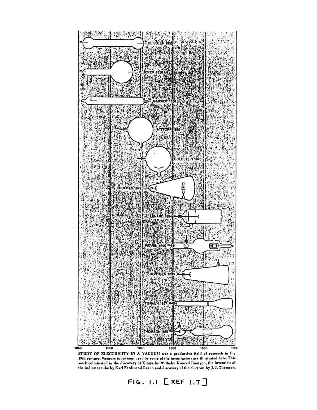
40
41
42
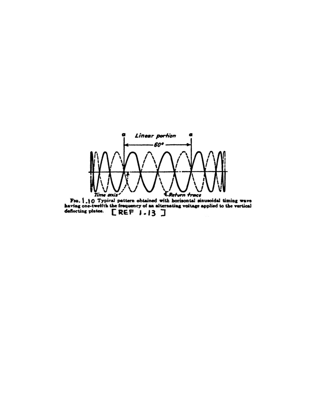
43
44
45
46
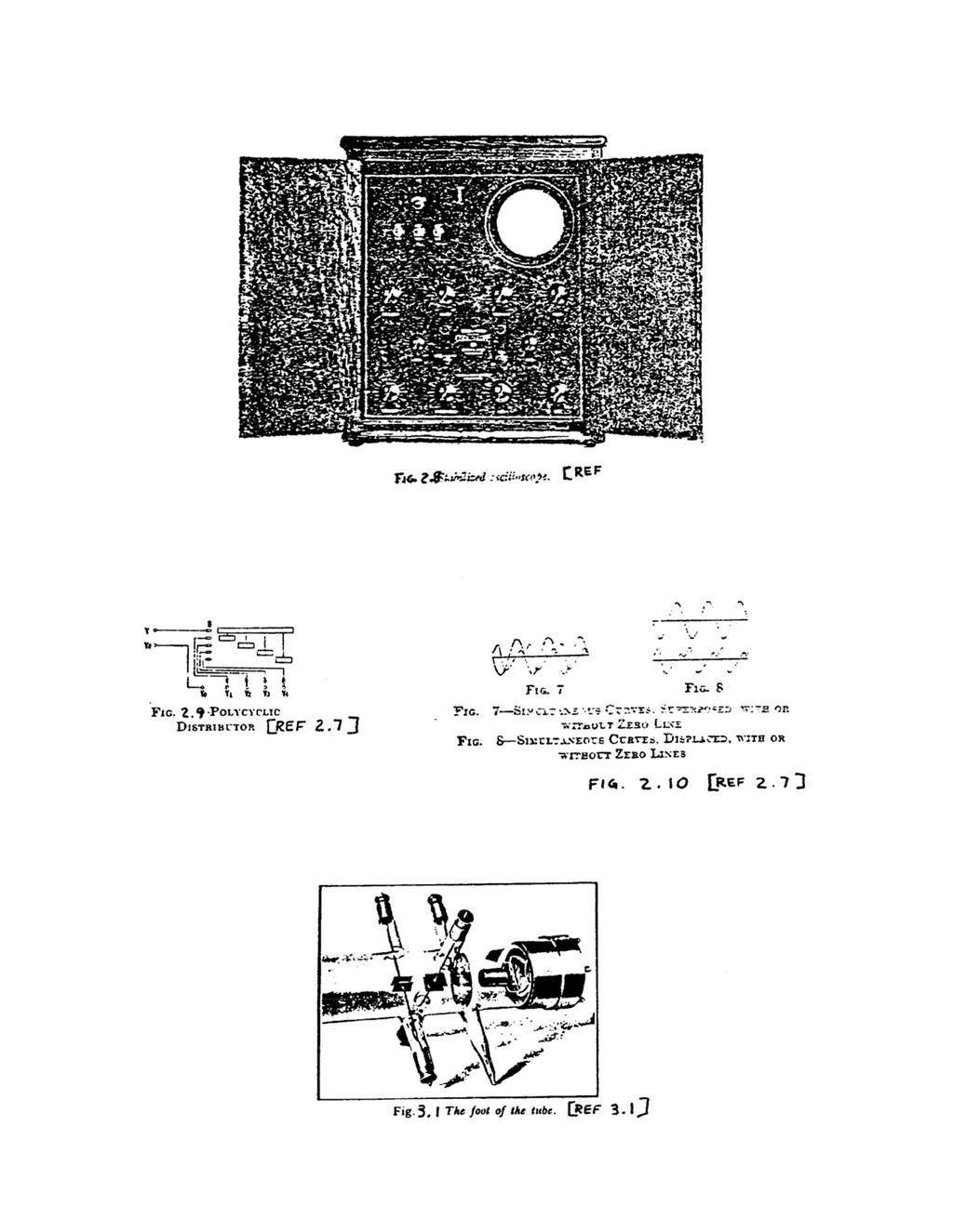
47
48
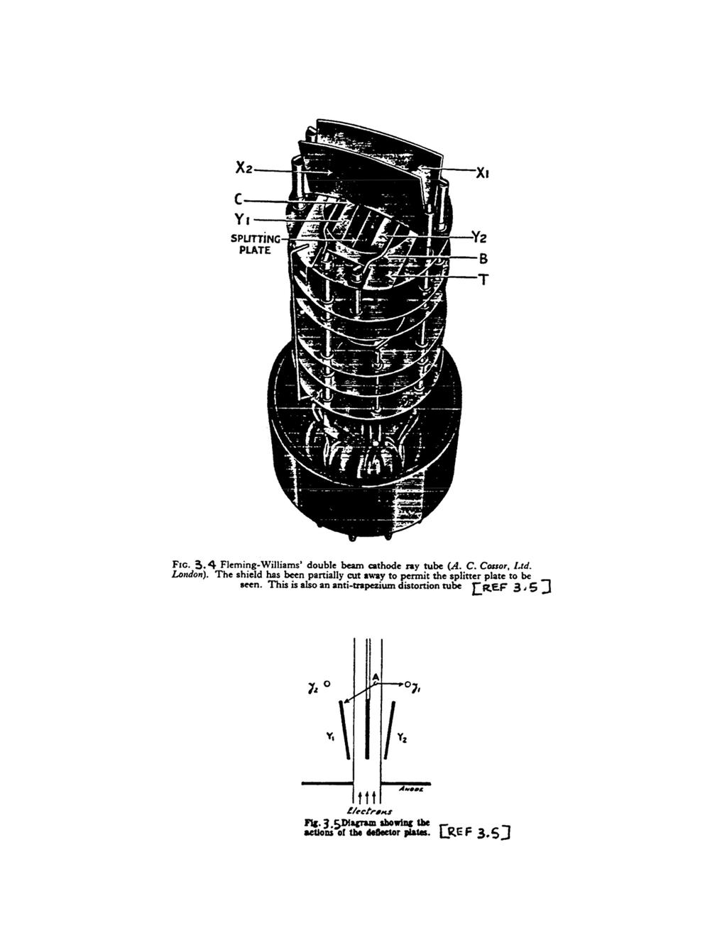
49
CHAPTER 4 OSCILLOSCOPES
 CHAPTER 4 OSCILLOSCOPES 4.1 Introduction The cathode ray oscilloscope generally referred to as the oscilloscope, is probably the most versatile electrical measuring instrument available. Some of electrical
CATHODE RAY OSCILLOSCOPE. Basic block diagrams Principle of operation Measurement of voltage, current and frequency
 CATHODE RAY OSCILLOSCOPE Basic block diagrams Principle of operation Measurement of voltage, current and frequency 103 INTRODUCTION: The cathode-ray oscilloscope (CRO) is a multipurpose display instrument
The Cathode Ray Tube
 Lesson 2 The Cathode Ray Tube The Cathode Ray Oscilloscope Cathode Ray Oscilloscope Controls Uses of C.R.O. Electric Flux Electric Flux Through a Sphere Gauss s Law The Cathode Ray Tube Example 7 on an
CATHODE-RAY OSCILLOSCOPE (CRO)
") CATHODE-RAY OSCILLOSCOPE (CRO) I N T R O D U C T I O N : The cathode-ray oscilloscope (CRO) is a multipurpose display instrument used for the observation, measurement, and analysis of waveforms by plotting
CATHODE-RAY OSCILLOSCOPE (CRO) I N T R O D U C T I O N : The cathode-ray oscilloscope (CRO) is a multipurpose display instrument used for the observation, measurement, and analysis of waveforms by plotting
Electrical and Electronic Laboratory Faculty of Engineering Chulalongkorn University. Cathode-Ray Oscilloscope (CRO)
") 2141274 Electrical and Electronic Laboratory Faculty of Engineering Chulalongkorn University Cathode-Ray Oscilloscope (CRO) Objectives You will be able to use an oscilloscope to measure voltage, frequency
2141274 Electrical and Electronic Laboratory Faculty of Engineering Chulalongkorn University Cathode-Ray Oscilloscope (CRO) Objectives You will be able to use an oscilloscope to measure voltage, frequency
OSCILLOSCOPE AND DIGITAL MULTIMETER
 Exp. No #0 OSCILLOSCOPE AND DIGITAL MULTIMETER Date: OBJECTIVE The purpose of the experiment is to understand the operation of cathode ray oscilloscope (CRO) and to become familiar with its usage. Also
CATHODE RAY OSCILLOSCOPE (CRO)
") CATHODE RAY OSCILLOSCOPE (CRO) 4.6 (a) Cathode rays CORE Describe the production and detection of cathode rays Describe their deflection in electric fields State that the particles emitted in thermionic
CATHODE RAY OSCILLOSCOPE (CRO) 4.6 (a) Cathode rays CORE Describe the production and detection of cathode rays Describe their deflection in electric fields State that the particles emitted in thermionic
Elements of a Television System
 1 Elements of a Television System 1 Elements of a Television System The fundamental aim of a television system is to extend the sense of sight beyond its natural limits, along with the sound associated
CHAPTER 3 OSCILLOSCOPES AND SIGNAL GENERATOR
 CHAPTER 3 OSCILLOSCOPES AND SIGNAL GENERATOR OSCILLOSCOPE 3.1 Introduction The cathode ray oscilloscope (CRO) provides a visual presentation of any waveform applied to the input terminal. The oscilloscope
J.J. Thomson, Cathode Rays and the Electron
 Introduction Experimenters had noticed that sparks travel through rarefied (i.e. low pressure) air since the time of Franklin. The basic setup was to have two metal plates inside a glass tube. The air
The Knowledge Bank at The Ohio State University. Ohio State Engineer
 The Knowledge Bank at The Ohio State University Ohio State Engineer Title: Creators: Principles of Electron Tubes Lamoreaux, Yvonne Issue Date: 1944-03 Publisher: Ohio State University, College of Engineering
RICHLAND COLLEGE School of Engineering Business & Technology Rev. 0 W. Slonecker Rev. 1 (8/26/2012) J. Bradbury
 J. Bradbury") RICHLAND COLLEGE School of Engineering Business & Technology Rev. 0 W. Slonecker Rev. 1 (8/26/2012) J. Bradbury INTC 1307 Instrumentation Test Equipment Teaching Unit 8 Oscilloscopes Unit 8: Oscilloscopes
RICHLAND COLLEGE School of Engineering Business & Technology Rev. 0 W. Slonecker Rev. 1 (8/26/2012) J. Bradbury INTC 1307 Instrumentation Test Equipment Teaching Unit 8 Oscilloscopes Unit 8: Oscilloscopes
INSTRUMENT CATHODE-RAY TUBE
 Instrument cathode-ray tube D14-363GY/123 INSTRUMENT CATHODE-RAY TUBE mono accelerator 14 cm diagonal rectangular flat face internal graticule low power quick heating cathode high brightness, long-life
Teltron Delection Tube D
 Teltron Delection Tube D 1011119 Overview The electron-beam deflection tube is intended for investigating the deflection of electron beams in electrical and magnetic fields. It can be used to estimate
2.2. VIDEO DISPLAY DEVICES
 Introduction to Computer Graphics (CS602) Lecture 02 Graphics Systems 2.1. Introduction of Graphics Systems With the massive development in the field of computer graphics a broad range of graphics hardware
4.9 BEAM BLANKING AND PULSING OPTIONS
 4.9 BEAM BLANKING AND PULSING OPTIONS Beam Blanker BNC DESCRIPTION OF BLANKER CONTROLS Beam Blanker assembly Electron Gun Controls Blanker BNC: An input BNC on one of the 1⅓ CF flanges on the Flange Multiplexer
These are used for producing a narrow and sharply focus beam of electrons.
 CATHOD RAY TUBE (CRT) A CRT is an electronic tube designed to display electrical data. The basic CRT consists of four major components. 1. Electron Gun 2. Focussing & Accelerating Anodes 3. Horizontal
3B SCIENTIFIC PHYSICS
 B SCIENTIFIC PHYSICS Triode S 11 Instruction sheet 1/15 ALF 1 5 7 1 Guide pin Connection pins Cathode plate Heater filament 5 Grid Anode 7 -mm plug for connecting anode 1. Safety instructions Hot cathode
Sep 09, APPLICATION NOTE 1193 Electronic Displays Comparison
 Sep 09, 2002 APPLICATION NOTE 1193 Electronic s Comparison Abstract: This note compares advantages and disadvantages of Cathode Ray Tubes, Electro-Luminescent, Flip- Dot, Incandescent Light Bulbs, Liquid
S op o e p C on o t n rol o s L arni n n i g n g O bj b e j ctiv i e v s
 ET 150 Scope Controls Learning Objectives In this lesson you will: learn the location and function of oscilloscope controls. see block diagrams of analog and digital oscilloscopes. see how different input
INSTRUMENT CATHODE-RAY TUBE
 INSTRUMENT CATHODE-RAY TUBE 14 cm diagonal rectangular flat face domed mesh post-deflection acceleration improved spot quality for character readout high precision by internal permanent magnetic correction
THE OPERATION OF A CATHODE RAY TUBE
 THE OPERATION OF A CATHODE RAY TUBE OBJECT: To acquaint the student with the operation of a cathode ray tube, and to study the effect of varying potential differences on accelerated electrons. THEORY:
THE OPERATION OF A CATHODE RAY TUBE
 THE OPERATION OF A CATHODE RAY TUBE OBJECT: To acquaint the student with the operation of a cathode ray tube, and to study the effect of varying potential differences on accelerated electrons. THEORY:
PRACTICAL APPLICATIONS OF ELECTRONICS IN ANAESTHESIA. G. A. HAY Department of Medical Physics, University of Leeds
 Brit. J. Anaesth. (1955), 27, 622 PRACTICAL APPLICATIONS OF ELECTRONICS IN ANAESTHESIA 1 BY G. A. HAY Department of Medical Physics, University of Leeds PART I: BASIC PRINCIPLES IN the last twenty years
OPERATING INSTRUCTIONS FOR SYLVANIA. Type I08 Cathode-Ray Oscilloscope. Sylvania Electric Products Inc. Industrial Apparatus. Emporium, Pennsylvania
 OPERATING INSTRUCTIONS FOR SYLVANIA Type I08 Cathode-Ray Oscilloscope Sylvania Electric Products Inc. Industrial Apparatus Plant Emporium, Pennsylvania OPERATING INSTRUCTIONS FOR Sylvania Type 08 Cathode-Ray
Using an oscilloscope - The Hameg 203-6
 Using an oscilloscope - The Hameg 203-6 What does an oscilloscope do? Setting up How does an oscilloscope work? Other oscilloscope controls Connecting a function generator Microphones audio signals and
Lecture 17 Microwave Tubes: Part I
 Basic Building Blocks of Microwave Engineering Prof. Amitabha Bhattacharya Department of Electronics and Communication Engineering Indian Institute of Technology, Kharagpur Lecture 17 Microwave Tubes:
Experiment 9A: Magnetism/The Oscilloscope
 Experiment 9A: Magnetism/The Oscilloscope (This lab s "write up" is integrated into the answer sheet. You don't need to attach a separate one.) Part I: Magnetism and Coils A. Obtain a neodymium magnet
Laser Beam Analyser Laser Diagnos c System. If you can measure it, you can control it!
 Laser Beam Analyser Laser Diagnos c System If you can measure it, you can control it! Introduc on to Laser Beam Analysis In industrial -, medical - and laboratory applications using CO 2 and YAG lasers,
THE CATHODE -RAY OSCILLOSCOPE
 THE CATHODE -RAY OSCILLOSCOPE %ssok RRT -20 2533 N. Ashland Ave., Chicago 14, Illinois Radio Reception and Transmission LESSON RRT -20 THE CATHODE -RAY OSCILLOSCOPE CHRONOLOGICAL HISTORY OF RADIO AND
Tutorial Cathode Rays Year 12 Physics - Module 9.3 Motors and Generators
 Tutorial 9.4.1.2 Cathode Rays Year 12 Physics - Module 9.3 Motors and Generators For use with Lesson 9.4.1 Cathode Rays 1. Identify the properties of cathode rays that indicated that they might be particles.
Cathode Ray Oscilloscope
 Lesson: Cathode Ray Oscilloscope Author: Dr. Arijit Chowdhuri College/ Department: Acharya Narendra Dev College, University of Delhi 1 Cathode Ray Oscilloscope (CRO) Introduction During a typical teaching-learning
CR7000. CRT Analyzer & Restorer. Easily Test And Restore CRTs With The Most Complete Tests Available For Added Profit And Security.
 CR7000 CRT Analyzer & Restorer Easily Test And Restore CRTs With The Most Complete Tests Available For Added Profit And Security. S1 New Demands From Higher Performance CRTs Require New Analyzing Techniques
Reading 21 ELECTRON TUBES
 Reading 21 Ron Bertrand VK2DQ http://www.radioelectronicschool.com ELECTRON TUBES One of the most significant developments of the early twentieth century was the invention of the electron tube. The British
3B SCIENTIFIC PHYSICS
 3B SCIENTIFIC PHYSICS Complete Fine Beam Tube System 1013843 Instruction sheet 10/15 SD/ALF If it is to be expected that safe operation is impossible (e.g., in case of visible damage), the apparatus is
In the tube collection there are several sensors designed for applications in some kinds of physics measurements or detection.
 8.2 Sensors In the tube collection there are several sensors designed for applications in some kinds of physics measurements or detection. 8.2.1 Displacement, vibration sensors Some tubes were devised
UNIT-3 Part A. 2. What is radio sonde? [ N/D-16]
![UNIT-3 Part A. 2. What is radio sonde? [ N/D-16]](/thumbs/88/116973079.jpg "UNIT-3 Part A. 2. What is radio sonde? [ N/D-16]") UNIT-3 Part A 1. What is CFAR loss? [ N/D-16] Constant false alarm rate (CFAR) is a property of threshold or gain control devices that maintain an approximately constant rate of false target detections
UNIT-3 Part A 1. What is CFAR loss? [ N/D-16] Constant false alarm rate (CFAR) is a property of threshold or gain control devices that maintain an approximately constant rate of false target detections
KLYSTRON GUN ARCING AND MODULATOR PROTECTION
 SLAC-PUB-10435 KLYSTRON GUN ARCING AND MODULATOR PROTECTION S.L. Gold Stanford Linear Accelerator Center (SLAC), Menlo Park, CA USA Abstract The demand for 500 kv and 265 amperes peak to power an X-Band
decodes it along with the normal intensity signal, to determine how to modulate the three colour beams.
 Television Television as we know it today has hardly changed much since the 1950 s. Of course there have been improvements in stereo sound and closed captioning and better receivers for example but compared
DEPARTMENT OF THE ARMY TECHNICAL BULLETIN CALIBRATION PROCEDURE FOR AUTOMATIC VIDEO CORRECTOR TEKTRONIX, MODEL 1440 (NSN )
") DEPARTMENT OF THE ARMY TECHNICAL BULLETIN TB 11-5820-861-35 CALIBRATION PROCEDURE FOR AUTOMATIC VIDEO CORRECTOR TEKTRONIX, MODEL 1440 (NSN 5820-00-570-1978) Headquarters, Department of the Army, Washington,
DEPARTMENT OF THE ARMY TECHNICAL BULLETIN TB 11-5820-861-35 CALIBRATION PROCEDURE FOR AUTOMATIC VIDEO CORRECTOR TEKTRONIX, MODEL 1440 (NSN 5820-00-570-1978) Headquarters, Department of the Army, Washington,
Tutorial: Trak design of an electron injector for a coupled-cavity linear accelerator
 Tutorial: Trak design of an electron injector for a coupled-cavity linear accelerator Stanley Humphries, Copyright 2012 Field Precision PO Box 13595, Albuquerque, NM 87192 U.S.A. Telephone: +1-505-220-3975
Analog Circuits Prof. Nagendra Krishnapura Department of Electrical Engineering Indian Institute of Technology, Madras. Module - 04 Lecture 12
 Analog Circuits Prof. Nagendra Krishnapura Department of Electrical Engineering Indian Institute of Technology, Madras Module - 04 Lecture 12 So, far we have discussed common source amplifier using an
Television brian egan isnm 2004
 Introduction Mechanical early developments. Electrical how it works. Digital advantages over analogue. brian egan isnm Mechanical television First televisions were mechanical based on revolving disc, first
Overview of All Pixel Circuits for Active Matrix Organic Light Emitting Diode (AMOLED)
") Chapter 2 Overview of All Pixel Circuits for Active Matrix Organic Light Emitting Diode (AMOLED) ---------------------------------------------------------------------------------------------------------------
Chapter 2 Overview of All Pixel Circuits for Active Matrix Organic Light Emitting Diode (AMOLED) ---------------------------------------------------------------------------------------------------------------
Commissioning the TAMUTRAP RFQ cooler/buncher. E. Bennett, R. Burch, B. Fenker, M. Mehlman, D. Melconian, and P.D. Shidling
 Commissioning the TAMUTRAP RFQ cooler/buncher E. Bennett, R. Burch, B. Fenker, M. Mehlman, D. Melconian, and P.D. Shidling In order to efficiently load ions into a Penning trap, the ion beam should be
Design and Simulation of High Power RF Modulated Triode Electron Gun. A. Poursaleh
 Design and Simulation of High Power RF Modulated Triode Electron Gun A. Poursaleh National Academy of Sciences of Armenia, Institute of Radio Physics & Electronics, Yerevan, Armenia poursaleh83@yahoo.com
Practical Application of the Phased-Array Technology with Paint-Brush Evaluation for Seamless-Tube Testing
 ECNDT 2006 - Th.1.1.4 Practical Application of the Phased-Array Technology with Paint-Brush Evaluation for Seamless-Tube Testing R.H. PAWELLETZ, E. EUFRASIO, Vallourec & Mannesmann do Brazil, Belo Horizonte,
PRACTICAL APPLICATION OF THE PHASED-ARRAY TECHNOLOGY WITH PAINT-BRUSH EVALUATION FOR SEAMLESS-TUBE TESTING
 PRACTICAL APPLICATION OF THE PHASED-ARRAY TECHNOLOGY WITH PAINT-BRUSH EVALUATION FOR SEAMLESS-TUBE TESTING R.H. Pawelletz, E. Eufrasio, Vallourec & Mannesmann do Brazil, Belo Horizonte, Brazil; B. M. Bisiaux,
The Venerable Triode. The earliest Triode was Lee De Forest's 1906 Audion.
 The Venerable Triode The very first gain device, the vacuum tube Triode, is still made after more than a hundred years, and while it has been largely replaced by other tubes and the many transistor types,
Display Technologies CMSC 435. Slides based on Dr. Luebke s slides
 Display Technologies CMSC 435 Slides based on Dr. Luebke s slides Recap: Transforms Basic 2D Transforms: Scaling, Shearing, Rotation, Reflection, Composition of 2D Transforms Basic 3D Transforms: Rotation,
Types of CRT Display Devices. DVST-Direct View Storage Tube
 Examples of Computer Graphics Devices: CRT, EGA(Enhanced Graphic Adapter)/CGA/VGA/SVGA monitors, plotters, data matrix, laser printers, Films, flat panel devices, Video Digitizers, scanners, LCD Panels,
Light Emitting Diodes
 By Kenneth A. Kuhn Jan. 10, 2001, rev. Feb. 3, 2008 Introduction This brief introduction and discussion of light emitting diode characteristics is adapted from a variety of manufacturer data sheets and
Basically we are fooling our brains into seeing still images at a fast enough rate so that we think its a moving image.
 Basically we are fooling our brains into seeing still images at a fast enough rate so that we think its a moving image. The formal definition of a Moving Picture... A sequence of consecutive photographic
Presented by: Amany Mohamed Yara Naguib May Mohamed Sara Mahmoud Maha Ali. Supervised by: Dr.Mohamed Abd El Ghany
 Presented by: Amany Mohamed Yara Naguib May Mohamed Sara Mahmoud Maha Ali Supervised by: Dr.Mohamed Abd El Ghany Analogue Terrestrial TV. No satellite Transmission Digital Satellite TV. Uses satellite
Klystron Tubes. Two forms of such a device, also called linear beam klystron, are given in the following figure.
 Klystron Tubes Go to the klystron index The principle of velocity-variation, first used in Heil oscillators, was also used in other microwave amplifying and oscillating tubes. The application for klystron
TECHNICAL SPECIFICATION Multi-beam S-band Klystron type BT267
 TECHNICAL SPECIFICATION Multi-beam S-band Klystron type BT267 The company was created for the development and manufacture of precision microwave vacuum-electron-tube devices (VETD). The main product areas
Computer Graphics : Unit - I
 Computer Graphics Unit 1 Introduction: Computer Graphics it is a set of tools to create, manipulate and interact with pictures. Data is visualized through geometric shapes, colors and textures. Video Display
Advanced Test Equipment Rentals ATEC (2832)
") E stablished 1981 Advanced Test Equipment Rentals www.atecorp.com 800-404-ATEC (2832) Technical Datasheet Scalar Network Analyzer Model 8003-10 MHz to 40 GHz The Giga-tronics Model 8003 Precision Scalar
E stablished 1981 Advanced Test Equipment Rentals www.atecorp.com 800-404-ATEC (2832) Technical Datasheet Scalar Network Analyzer Model 8003-10 MHz to 40 GHz The Giga-tronics Model 8003 Precision Scalar
SERVICING TELEVISION VOLUME 2 G. N. PATCHETT LONDON: NORMAN PRICE (PUBLISHERS) LTD. The Cathode Ray Tube. Sawtooth Current Generators
 LTD. The Cathode Ray Tube. Sawtooth Current Generators") m 3 TELEVISION SERVICING VOLUME 2 The Cathode Ray Tube Synchronizing Separators Timebases Field Output Stage Line Output Stage Sawtooth Current Generators G. N. PATCHETT B.Sc. (Eng.)., Ph.D., C. Eng.,
m 3 TELEVISION SERVICING VOLUME 2 The Cathode Ray Tube Synchronizing Separators Timebases Field Output Stage Line Output Stage Sawtooth Current Generators G. N. PATCHETT B.Sc. (Eng.)., Ph.D., C. Eng.,
Modify the UL40-S2 into a Super-Triode amplifier. Ir. Menno van der Veen
 Modify the UL40-S2 into a Super-Triode amplifier Ir. Menno van der Veen Introduction about modifications: The UL40-S2 is already some years on the market and meanwhile I have received several requests
Burlington County College INSTRUCTION GUIDE. for the. Hewlett Packard. FUNCTION GENERATOR Model #33120A. and. Tektronix
 v1.2 Burlington County College INSTRUCTION GUIDE for the Hewlett Packard FUNCTION GENERATOR Model #33120A and Tektronix OSCILLOSCOPE Model #MSO2004B Summer 2014 Pg. 2 Scope-Gen Handout_pgs1-8_v1.2_SU14.doc
The Distortion Magnifier
 The Distortion Magnifier Bob Cordell January 13, 2008 Updated March 20, 2009 The Distortion magnifier described here provides ways of measuring very low levels of THD and IM distortions. These techniques
Sealed Linear Encoders with Single-Field Scanning
 Linear Encoders Angle Encoders Sealed Linear Encoders with Single-Field Scanning Rotary Encoders 3-D Touch Probes Digital Readouts Controls HEIDENHAIN linear encoders are used as position measuring systems
Display Devices & its Interfacing
 Display Devices & its Interfacing 3 Display systems are available in various technologies such as i) Cathode ray tubes (CRTs), ii) Liquid crystal displays (LCDs), iii) Plasma displays, and iv) Light emitting
K800 RF AMPLIFIER TUBE UPGRADE
 R. F. Note 107 John Vincent August 5, 1988 K800 RF AMPLIFIER TUBE UPGRADE Contents: 1. Introduction 2. RCA 4648 Operating Experience and Evaluation. 3. Tube Selection Criteria 4. Cost and Availability
 Patented Nov. 14, 1950 2,529,485 UNITED STATES PATENT OFFICE 1 This invention relates to television systems and more particularly to methods of and means for producing television images in their natural
VARIOUS DISPLAY TECHNOLOGIESS
 VARIOUS DISPLAY TECHNOLOGIESS Mr. Virat C. Gandhi 1 1 Computer Department, C. U. Shah Technical Institute of Diploma Studies Abstract A lot has been invented from the past till now in regards with the
Brown, A., Merkert, J., & Wilson, R. (2014). Build your own particle accelerator. Science in School, (30),
. Build your own particle accelerator. Science in School, (30),") Brown, A., Merkert, J., & Wilson, R. (2014). Build your own particle accelerator. Science in School, (30), 21-26. Publisher's PDF, also known as Version of record License (if available): CC BY-NC-SA Link
Brown, A., Merkert, J., & Wilson, R. (2014). Build your own particle accelerator. Science in School, (30), 21-26. Publisher's PDF, also known as Version of record License (if available): CC BY-NC-SA Link
Development of Multiple Beam Guns for High Power RF Sources for Accelerators and Colliders
 SLAC-PUB-10704 Development of Multiple Beam Guns for High Power RF Sources for Accelerators and Colliders R. Lawrence Ives*, George Miram*, Anatoly Krasnykh @, Valentin Ivanov @, David Marsden*, Max Mizuhara*,
Interaction of Infrared Controls And Fluorescent Lamp/Ballast Systems In Educational Facilities
 LSD 6-1999 A NEMA Lighting Systems Division Document Interaction of Infrared Controls And Fluorescent Lamp/Ballast Systems In Educational Facilities Prepared by Lamp Section Ballast Section National Electrical
B. TECH. VI SEM. I MID TERM EXAMINATION 2018
 B. TECH. VI SEM. I MID TERM EXAMINATION 2018 BRANCH : COMPUTER SCIENCE ENGINEERING ( CSE ) SUBJECT : 6CS4A COMPUTER GRAPHICS & MULTIMEDIA TECHNIQUES Q 1. Write down mid point ellipse drawing algorithm.
MTI-2100 FOTONIC SENSOR. High resolution, non-contact. measurement of vibration. and displacement
 A worldwide leader in precision measurement solutions MTI-2100 FOTONIC SENSOR High resolution, non-contact measurement of vibration and displacement MTI-2100 Fotonic TM Sensor Unmatched Resolution and
Quality produced by means of electron beam
 Quality produced by means of electron beam EB-generators by Steigerwald Strahltechnik tradition and innovation In material processings Steigerwald Strahltechnik has been well known for its production and
Electro-Optic Beam Deflectors
 Toll Free: 800 748 3349 Electro-Optic Beam Deflectors Conoptics series of electro-optic beam deflectors utilize a quadrapole electric field in an electro-optic material to produce a linear refractive index
Television Projects of Fernseh GmbH (Int. Dr. Möller)
") Section 2.4 (6) A.L. No. 41 (Sheet 1) 3/12/45 Television Projects of Fernseh GmbH (Int. Dr. Möller) During the war, Fernseh worked on a number of television projects. Those described by Möller are listed
Section 2.4 (6) A.L. No. 41 (Sheet 1) 3/12/45 Television Projects of Fernseh GmbH (Int. Dr. Möller) During the war, Fernseh worked on a number of television projects. Those described by Möller are listed
PTIK UNNES. Lecture 02. Conceptual Model for Computer Graphics and Graphics Hardware Issues
 E3024031 KOMPUTER GRAFIK E3024032 PRAKTIK KOMPUTER GRAFIK PTIK UNNES Lecture 02 Conceptual Model for Computer Graphics and Graphics Hardware Issues 2014 Learning Objectives After carefully listening this
Innovative Rotary Encoders Deliver Durability and Precision without Tradeoffs. By: Jeff Smoot, CUI Inc
 Innovative Rotary Encoders Deliver Durability and Precision without Tradeoffs By: Jeff Smoot, CUI Inc Rotary encoders provide critical information about the position of motor shafts and thus also their
PERFORMANCE SPECIFICATION SHEET ELECTRON TUBE, CATHODE RAY TYPE 7AGP19
 INCH-POUND MIL-PRF-1/1178E 22 July 1999 SUPERSEDING MIL-E-1/1178D(EC) 23 December 1976 PERFORMANCE SPECIFICATION SHEET ELECTRON TUBE, CATHODE RAY TYPE 7AGP19 This specification is approved for use by all
PAST EXAM PAPER & MEMO N3 ABOUT THE QUESTION PAPERS:
 EKURHULENI TECH COLLEGE. No. 3 Mogale Square, Krugersdorp. Website: www. ekurhulenitech.co.za Email: info@ekurhulenitech.co.za TEL: 011 040 7343 CELL: 073 770 3028/060 715 4529 PAST EXAM PAPER & MEMO N3
Standby...For the Truth
 Innovation. Amplified. Chapter 6 Standby...For the Truth by Hartley Peavey Standby for the Truth Incredibly, very few modern technicians (and even fewer players) understand why so-called standby switches
Duke University. Plasma Display Panel. A vanished technique
 Duke University Plasma Display Panel A vanished technique Yida Chen Dr. Hubert Bray Math 190s: Mathematics of the Universe 31 July 2017 Introduction With the establishment of the atomic theory, we begin
16 Stage Bi-Directional LED Sequencer
 16 Stage Bi-Directional LED Sequencer The bi-directional sequencer uses a 4 bit binary up/down counter (CD4516) and two "1 of 8 line decoders" (74HC138 or 74HCT138) to generate the popular "Night Rider"
University of Utah Electrical & Computer Engineering Department ECE1050/1060 Oscilloscope
 University of Utah Electrical & Computer Engineering Department ECE1050/1060 Oscilloscope Name:, A. Stolp, 2/2/00 rev, 9/15/03 NOTE: This is a fill-in-the-blanks lab. No notebook is required. You are encouraged
Choosing an Oscilloscope
 Choosing an Oscilloscope By Alan Lowne CEO Saelig Company (www.saelig.com) Post comments on this article at www.nutsvolts.com/ magazine/article/october2016_choosing-oscilloscopes. All sorts of questions
HIGH VOLTAGE SWITCH PERFORMANCE OF THE EIMAC X-2159 TETRODE ABSTRACT
 HIGH VOLTAGE SWITCH PERFORMANCE OF THE EIMAC X-2159 TETRODE by Bobby R. Gray High Power Component & Effects Section Techniques Branch Surveillance Division Rome Air Development Center Griffiss Air Force
A HIGH POWER LONG PULSE HIGH EFFICIENCY MULTI BEAM KLYSTRON
 A HIGH POWER LONG PULSE HIGH EFFICIENCY MULTI BEAM KLYSTRON A.Beunas and G. Faillon Thales Electron Devices, Vélizy, France S. Choroba DESY, Hamburg, Germany Abstract THALES ELECTRON DEVICES has developed
MultiMac. Eddy Current Instrument for Encircling Coil, Sector and Rotary Probe Testing of Tube, Bar, & Wire
 MultiMac Eddy Current Instrument for Encircling Coil, Sector and Rotary Probe Testing of Tube, Bar, & Wire Inspection Features Versatile Threshold Selection Challenging test conditions are made simple
Electrical & Electronic Measurements: Class Notes (15EE36) Module-5. Display Devices
 Module-5. Display Devices") Module-5 Display Devices Syllabus: Introduction Character formats Segment displays Dot matrix displays Bar graph displays Cathode ray tubes Light emitting diodes Liquid crystal displays Nixies Incandescent
Module-5 Display Devices Syllabus: Introduction Character formats Segment displays Dot matrix displays Bar graph displays Cathode ray tubes Light emitting diodes Liquid crystal displays Nixies Incandescent
Making the tracks on video tape visible with a magnetic fluid
 Philips tech. Rev. 40,129-132, 1982, No. 5 129 Making the tracks on video tape visible with a magnetic fluid A. M. A. Rijckaert It has been known for more than fifty years that magnetic effects at the
Monitor QA Management i model
 Monitor QA Management i model 1/10 Monitor QA Management i model Table of Contents 1. Preface ------------------------------------------------------------------------------------------------------- 3 2.
Display Systems. Viewing Images Rochester Institute of Technology
 Display Systems Viewing Images 1999 Rochester Institute of Technology In This Section... We will explore how display systems work. Cathode Ray Tube Television Computer Monitor Flat Panel Display Liquid
NAPIER. University School of Engineering. Advanced Communication Systems Module: SE Television Broadcast Signal.
 NAPIER. University School of Engineering Television Broadcast Signal. luminance colour channel channel distance sound signal By Klaus Jørgensen Napier No. 04007824 Teacher Ian Mackenzie Abstract Klaus
CHAPTER 3 SEPARATION OF CONDUCTED EMI
 54 CHAPTER 3 SEPARATION OF CONDUCTED EMI The basic principle of noise separator is described in this chapter. The construction of the hardware and its actual performance are reported. This chapter proposes
Digital High Resolution Display Technology. A New Way of Seeing Things.
 R Digital High Resolution Display Technology A New Way of Seeing Things. Raytheon s Digital Display Digital Light Processing (DLP ) by Texas Instruments is a revolutionary new way to project and display
Svetlana 3CX10,000A7/8160
 Svetlana 3CX1,A7/816 High-Mu Power Triode T he Svetlana 3CX1,A7/816 is a high-performance ceramic/metal power triode designed for use in zero-bias, class B RF or audio amplifiers. A modern mesh filament
Monitor and Display Adapters UNIT 4
 Monitor and Display Adapters UNIT 4 TOPIC TO BE COVERED: 4.1: video Basics(CRT Parameters) 4.2: VGA monitors 4.3: Digital Display Technology- Thin Film Displays, Liquid Crystal Displays, Plasma Displays
The Use of an Electron Microchannel as a Self-Extracting and Focusing Plasma Cathode Electron Gun
 The Use of an Electron Microchannel as a Self-Extracting and Focusing Plasma Cathode Electron Gun S. CORNISH, J. KHACHAN School of Physics, The University of Sydney, Sydney, NSW 6, Australia Abstract A
CM-1UTP CAMERA MASTER UTP ADAPTOR
 CM-1UTP CAMERA MASTER UTP ADAPTOR INSTRUCTION BOOK CM-1UTP.ISB TABLE OF CONTENTS FORWARD 2 VIDEO STANDARDS 2 COAXIAL CABLE vs UTP WIRE CABLE 3 MEASUREMENT 3 MOUNTING THE CM1-UTP ADAPTOR 3 UTP WIRE CABLE
Digital Delay / Pulse Generator DG535 Digital delay and pulse generator (4-channel)
") Digital Delay / Pulse Generator Digital delay and pulse generator (4-channel) Digital Delay/Pulse Generator Four independent delay channels Two fully defined pulse channels 5 ps delay resolution 50 ps
Digital Delay / Pulse Generator Digital delay and pulse generator (4-channel) Digital Delay/Pulse Generator Four independent delay channels Two fully defined pulse channels 5 ps delay resolution 50 ps
ECE 5765 Modern Communication Fall 2005, UMD Experiment 10: PRBS Messages, Eye Patterns & Noise Simulation using PRBS
 ECE 5765 Modern Communication Fall 2005, UMD Experiment 10: PRBS Messages, Eye Patterns & Noise Simulation using PRBS modules basic: SEQUENCE GENERATOR, TUNEABLE LPF, ADDER, BUFFER AMPLIFIER extra basic: