DMP900. Digital Media Platform. User s Manual V1.07-W
|
|
|
- Adam Hawkins
- 5 years ago
- Views:
Transcription
1 DMP900 Digital Media Platform User s Manual
2 About This Manual This manual describes the installation, setup and operation of the DMP900 in details. Please read it carefully to make sure you can operate the multiplexer correctly. Important Avoid personal injury and product damage! Do not proceed beyond any symbol until you fully understand the indicated conditions. You may find this symbol in the document that accompanies this product. This symbol indicates important operating or maintenance instructions. Please use the cable of good quality and make sure the connector is in good condition. Please do not use the power supply that doesn t match the requirement. Please do not open the machine cover. Specifications and functions may be changed for improvement without notice in advance. Notices Trademark Acknowledgments All trademarks shown in this manual are trademarks of their respective owners. Publication Disclaimer Wellav Technologies Ltd. assumes no responsibility for errors or omissions that may appear in this publication. We reserve the right to change this publication at any time without notice. This document is not to be construed as conferring by implication, estoppels, or otherwise any license or right under any copyright or patent, whether or not the use of any information in this document employs an invention claimed in any existing or later issued patent. 2 / 116
3 Copyright Information in this publication is subject to change without notice. No part of this publication may be reproduced or transmitted in any form, by photocopy, microfilm, xerography, or any other means, or incorporated into any information retrieval system, electronic or mechanical, for any purpose, without the express permission of Wellav Technologies Ltd. Safety Instructions This warning symbol means danger. You are in a situation that could cause bodily injury. Before you work on any equipment, be aware of the hazards involved with electrical circuitry and be familiar with standard practices for preventing accidents. Electric Shock Hazard This equipment meets applicable safety standards. Refer to this equipment's Identification label or contact factory for details about regulatory compliance approvals. WARNING: To reduce risk of electric shock, perform only the instructions that are included in the operating instructions. Refer all servicing and installation to qualified service personnel only. Electric shock can cause personal injury or even death. Avoid direct contact with dangerous voltages at all times. The protective ground connection, where provided, is essential to safe operation and must be verified before connecting the power supply. Know the following safety warnings and guidelines: - Only trained and qualified personnel should be allowed to install, replace, or service this equipment. - Only qualified service personnel are allowed to remove chassis covers and access any of the components inside the chassis. - No user-serviceable parts inside. Do not open. Important Safety Instructions Read these instructions. Keep these instructions. Heed all warnings. Follow all instructions. Do not use this apparatus near water. Clean only with dry cloth. 3 / 116
4 Do not block any ventilation openings. Install in accordance with the manufacturer's instructions. Do not install near any heat sources such as radiators, heat registers, stoves, or other apparatus (including amplifiers) that produce heat. Protect the power cord from being walked on or pinched particularly at plugs, convenience receptacles, and the point where they exit from the apparatus. Only use attachments/accessories specified by the manufacturer. Use only with the cart, stand, tripod, bracket, or table specified by the manufacturer, or sold with the apparatus. When a cart is used, use caution when moving the cart/apparatus combination to avoid injury from tip-over. Unplug this apparatus during lightning storms or when unused for long periods of time. Refer all servicing to qualified service personnel. Servicing is required when the apparatus has been damaged in any way, such as power-supply cord or plug is damaged, liquid has been spilled or objects have fallen into the apparatus, the apparatus has been exposed to rain or moisture, does not operate normally, or has been dropped. WARNING: To reduce the risk of fire or electric shock, do not expose this apparatus to rain or moisture. The apparatus shall not be exposed to dripping or splashing and no objects filled with liquids, such as vases, shall be placed on the apparatus. Installation Site When selecting the installation site, comply with the following: Protective Ground - The protective ground lead of the building's electrical installation should comply with national and local requirements. Environmental Condition - The installation site should be dry, clean, and ventilated. Do not use this equipment where it could be at risk of contact with water. Installation Requirements Installation of the equipment must comply with local and national electrical codes. Equipment Placement Make sure the mounting surface or rack is stable and can support the size and weight of this equipment. The mounting surface or rack should be appropriately anchored according to manufacturer's specifications. Ensure this equipment is securely fastened to the mounting surface or rack where necessary to protect against damage due to any disturbance and subsequent fall. To prevent personal injury or damage to the chassis, never attempt to lift or tilt the chassis using the handles on modules (such as power supplies, fans, or cards); 4 / 116
5 these types of handles are not designed to support the weight of the unit. Installation of this equipment in a rack should be such that the amount of airflow required for safe operation of this equipment is not compromised. Only install this equipment in a humidity- and temperature-controlled environment that meets the requirements given in this equipment's technical specifications. AC Power This product requires short-circuit (overcurrent) protection to be provided as part of the building installation. Install only in accordance with national and local wiring regulations. The outlet must be near this equipment and must be easily accessible. Connect this equipment only to the power sources that are identified on the equipment-rating label normally located close to the power inlet connector(s). The plug-socket combination must be accessible at all times, because it serves as the main disconnecting device. Always pull on the plug or the connector to disconnect a cable. Never pull on the cable itself. Unplug this equipment when unused for long periods of time. Circuit Overload Know the effects of circuit overloading before connecting this equipment to the power supply. Take care when connecting units to the supply circuit so that wiring is not overloaded. WARNING: Consideration should be given to the connection of this equipment to the supply circuit and the effect that overloading of circuits might have on overcurrent protection and supply wiring. Appropriate consideration of information given on the equipment-rating label should be used when addressing this concern. General Servicing Precautions WARNING: Avoid electric shock! Opening or removing this equipment's cover may expose you to dangerous voltages. Be aware of the following general precautions and guidelines: Wristwatch and Jewelry - For personal safety and to avoid damage of this equipment during service and repair, do not wear electrically conducting objects such as a wristwatch or jewelry. Lightning - Do not work on the system or connect or disconnect cables during periods of lightning activity. Labels - Do not remove any warning labels. Replace damaged or illegible warning labels with new ones. 5 / 116
6 Covers - Do not open the cover of this equipment and attempt service unless instructed to do so in the instructions. Refer all servicing to qualified service personnel only. The covers are integral part of the safety design of the product. Do not operate the unit without the covers installed. Safety Checks - After service, assemble this equipment and perform safety checks to ensure it is safe to use before putting it back into operation. Electrostatic Discharge Electrostatic discharge (ESD) results from the static electricity buildup on the human body and other objects. This static discharge can degrade components and cause failures. Take the following precautions against electrostatic discharge: Use an anti-static bench mat and a wrist strap or ankle strap designed to safely ground ESD potentials through a resistive element. Keep components in their anti-static packaging until installed. Avoid touching electronic components when installing a module. 6 / 116
7 Contents CHAPTER1 DMP OVERVIEW GENERAL THE HOUSING FRONT PANEL & LED INDICATORS INTRODUCTION TO EACH I/O MODULE Modular Concept DVB-S/S2 module DVB-C/T module Gigabit IP module CI module ASI I/O module SD&HD H.264 SDI/AV Encoder module Gigabit Scrambler module QAM/4-COFDM module TC2 & TC4 Transcoder module CHAPTER2 INSTALLATION INTRODUCTION INSTALLATION PREPARATION OPERATING TEMPERATURE RACK MOUNTING Tools and Accessories Mounting Requirements Mounting the DMP CONNECTING THE AC POWER CABLING THE MANAGEMENT PORTS CHAPTER3 OPERATION GUIDE OPERATION THROUGH NETWORK MANAGEMENT SOFTWARE Assigning IP Addresses Main Interface Introduction Parameters Setting of the Mainboard Parameters Setting of the Sub-module Program Input and Output Operation / 116
8 3.1.6 Receiving Signal Auto- Backup Function Configuration importation and exportation OPERATION THROUGH FRONT PANEL Front Panel Control Buttons Front Panel Operation Menu Structure Front Panel Operation Procedure CHAPTER4 EQUIPMENT SPECIFICATIONS CHAPTER5 TERMINOLOGIES / 116
9 Chapter1 DMP Overview 1.1 General DMP900 Digital Media Platform is the new generation of intelligent headend processing equipment. With a central processing capability of 384 TS streams (~1500 programs), this compact, high density 1RU equipment comes with 6 independent module slots. All six modules can be hot-swapped and hot-inserted to support the growing requirements of network operators. Each module can be configured individually base on the application including receiving, encoding, decoding, transmodulating, transcoding, ASI to IP mutual conversion, scrambling, descrambling, multiplexing, and QAM/OFDM modulation. Of total 6 I/O slot, each I/O slot can be equipped with: an ASI Interface module containing 4 ASI ports for input/output stream a GbE Interface module containing one pair of Gigabit Ethernet ports for input and output IP stream a DVB-S/S2 module provided with 4 RF input ports a DVB-C/T module provided with 2 RF input ports (receive 4 frequencies) and 2 RF loop out ports a DVB-CI module containing dual CI slots a 8-QAM/4-OFDM module provided with 1 RF output ports a 4-OFDM module provided with 1 RF output ports a GbE interface scrambling module for up to 1G data scrambling a MPEG-2/MPEG-4 transcoder module a SD/HD H.264 HDMI encoder module a CVBS/HDMI decoder module a SD/HD SDI decoder module 1.2 The Housing The DMP housing is a compact, modular 1 RU high 19-inch chassis containing six I/O slots and two PSU slots. The housing is rear loadable, meaning the cards, PSUs, and slot cover plates are loaded via the rear panel of the housing. 9 / 116

10 Two PSU Slots Hot-swappable I/O module 1.3 Front Panel & LED Indicators LCD Display 2. Front panel operation Keys 10 / 116
11 3. Power indicator Power On: green LED indicator is ON Power Off: LED indicator is OFF 4. Mainboard indicator Green: normal Red: Error detected 5. Module indicator Green and flashing: module is under initiation Green: normal Red and flashing: initiation fails Red: error detected 6. Menu & OK operation buttons 7. Reset button 8. Ethernet interface for remote management control 1.4 Introduction to Each I/O Module Modular Concept The DMP fully incorporates the modular concept with built around a 1 RU high housing. The flexible modular concept ensures really easy system application switch and capacity upgrades. The following DMP module is available: 4-DVB-S/S2 module 4-DVB-C/T module Gigabit IP module CI module 4-ASI I/O module 2-SD&HD H.264 SDI/AV Encoder module Gigabit Scrambler module 8-QAM module 4-OFDM module 2-MPEG2 to MPEG4 Transcoder module More modules will be available at a later date. Please contact your service provider for the details. When the DMP leaves our assembly line, the device is configured as ordered. When the device is not fully populated, the device can always be upgraded at a later date by 11 / 116

12 adding or replacing different modules DVB-S/S2 module The DVB-S/S2 module is equipped with 4 BNC-type ASI interfaces ports. Each ASI interface can be connected to one single LNB cable of a dish and receive whole programs transmitted on a satellite transponder. Up to 5 DVB-S/S2 modules can be installed on a DMP unit, which means that one DMP can support up to 20 DVB-S/S2 input signals (20 transponders). Description Inputs Frequency Range Symbol Rate FEC Mode Input Level LNB Power Supply 22KHz Specification 4XRF inputs, 75Ω, F-type connector 950~2150MHz QPSK: 2~45MBauds 8PSK: 2~37Mbauds QPSK: 1/2, 2/3, 3/4, 5/6, 7/8 8PSK: 2/3, 3/4, 4/5, 5/6, 8/9, 9/10-65dBm~-25dBm Vertical: 11.5V~14.0V Horizontal: 16.0V~19.0V 18~26KHz 12 / 116
13 DVB-C/T module Similar to DVB-S/S2 module, this module is for receiving DVB-C/T signals, and each module can support up to 4 DVB-C/T signal receiving and loop out. One DMP supports to install a max of 5 DVB-C/T modules. Description Inputs Frequency Range Symbol Rate FEC Mode Input Level QAM Mode Specification 2XRF inputs, 75Ω, F-type connector 2Xloop out DVB-C module: 48~862MHz DVB-T module: 50~858MHz DVB-C module: 1.0~6.9MBauds DVB-T module: 0.45~7.0MBauds DVB-C module: Annex A/C, Annex B (optional) DVB-T module: 2K & 8K (FTT) DVB-C module: 32~105dBuV DVB-T module: -96~-6dBm 16/32/64/128/256 QAM 13 / 116
14 Gigabit IP module A GbE Interface Card of the DMP is provided with 2 Gigabit Ethernet interfaces, giving the card a total throughput of 1 Gbps in and 1 Gbps out. To protect video services transported over IP networks from impairments caused by network jitter, IP packet loss, or out-of-order IP packets, a GbE Interface Card with FEC option based on Pro-MPEG COP3 is provided. The following illustration depicts a standard GbE Interface Card and a GbE Interface Card with FEC option. Description Input/Output Gigabit-8 IP Max Input/Output Gigabit-32 IP Max Input/Output Error Correction Encapsulation Protocol Broadcasting Type Specification 2X1000Base-T, RJ45 (one for input/output; one for backup output) 8 input TS streams and 8 output TS streams 32 input TS streams and 32 output TS streams Pro-MPEG FEC MPEG-2/MPEG-4 TS over UDP/RTP Unicast & Multicast 14 / 116
15 CI module The CI module is with 2 independent common interface slots, which supports multi-channel descrambling by inserting different CAM modules. Description Specification Interface 2Xcommon Interface slots Standard DVB/NRSS-B/DAVIC V1.2 CA methods Multicrypt, Simulcrypt CAS support Conax, Irdeto, Viacess, CTI, Nagravision, DVCrypt, etc. 15 / 116
16 ASI I/O module The ASI Interface module of the DMP is provided with 4 BNC-type ASI interface ports, which can individually be configured as either ASI input port or ASI output port using the management software of the device. All ASI interface ports support Multiple Program Transport Streams (MPTS) as well as Single Program Transport Streams (SPTS) according to ISO/IEC Each DMP can be equipped with maximum six ASI Interface Modules, meaning that the device can support a max of 24 ASI interfaces. 16 / 116
17 SD&HD H.264 SDI/AV Encoder module The SD&HD H.264 encoder module supports two A/V and SD/HD SDI input streams encoding simultaneously. Due to the highly encoding efficiency of the H.264 technology, this encoder module enables the operator to encode the analog and SDI streams at very low bitrate for transmission. Description Specification Inputs 2 SDI, BNC 75Ω / 2 CVBS, 2 Audio inputs (balanced and unbalanced) Video Processing Video Format MPEG-4 / H.264-AVC HP@L4 Image Format PAL and NTSC 1920x1080x59.94i/50; 1440x1080x 59.94i/50i; Definition 1280x720x59.94p/50p; 720x480x59.94i; 720x576x50i Aspect ratio 4:3, 16:9 GOP configurable I, IP, IPB, IPBB Video bit rate CBR & VBR, SD 1.0~20Mbps; HD 6.0~20Mbps Audio Processing Audio Format MPEG-1 and MPEG-2 Layer-I, II, AAC, Dolby AC-3 (optional) Sampling frequency 48KHz Audio mode Stereo, joint stereo, dual channel, mono 17 / 116
18 Gigabit Scrambler module A GbE Interface Card of the DMP is provided with 1 Gigabit Ethernet interface which is used to communicate with CAS server. The card is capable of a total throughput of 1 Gbps in and 1 Gbps out. The module is fully compliant with DVB Simulcrypt standard and supports up to 4 different CAS Simulcrypt application. 18 / 116
19 QAM/4-COFDM module This modulation module supports either 8 channels QAM or 4 channels COFDM modulation output. With up to 5 modules on a single DMP unit, the DMP supports up to 40RF QAM or 20RF COFDM outputs. 19 / 116
20 TC2 & TC4 Transcoder module The TC2 & TC4 transcoder module is capable of transforming MPEG-4/H.264 programs to MPEG-2 encoding format (TC2) or reversely MPEG-2 to MPEG-4/H.264 transforming (TC4). On a single module, it is optionally to support up to 4 programs transcoding which enables as up to 20 programs transcoding processing on a DMP unit simultaneously. MPEG-4 to MEPG-2 Transcoder Module (TC2) Description Specification Video Processing Processing Channel Quantity 2 channels (default) 4 channels (optional) Video Output Format MPEG-2 4:2:0 MP@ML Video Standard PAL and NTSC Video Resolution 480i, 576i Aspect ratio 4:3, 16:9 Video encoding bit rate CBR & VBR, 1.0~20.0Mbps Audio Processing 20 / 116
21 Audio Format Sampling frequency Audio mode MPEG-1 Layer- I 64~384KHz Stereo, joint stereo, dual channel, single channel Description Video Processing Processing Channel Quantity Video Output Format Definition MPEG-2 to MEPG-4 Transcoder Module (TC4) Specification Aspect ratio 4:3, 16:9 Video bit rate 2 channels (default) 4 channels (optional) MPEG-4 / H.264-AVC HP@L4 1920x1080 (60p/59.94p/30p/24p/60i/59.94i/50i); 1280x720 (60p/59.94p/50p); 720x480 (60i); 720x576 (50i) CBR & VBR, 1.0~20Mbps Audio Processing Audio Format Sampling frequency MPEG-1/-2 Layer-I, II 64KHz~384KHz 21 / 116

22 Chapter2 Installation 2.1. Introduction This chapter contains the information for technicians installing the DMP900. WARNING: Allow only authorized and qualified service personnel to install, operate, maintain, and service this product. Otherwise, personal injury or equipment damage may occur Installation Preparation Before You Start Make sure that the chassis is in good condition and that you have the tools and equipment needed. Unpacking and Inspecting the Housing As you unpack the housing, inspect it for shipping damage. If you find any damage, contact the customer services department. Chassis Dimensions The following drawing shows the dimensions of the DMP. 490mm 44mm 440mm 22 / 116
23 2.3 Operating Temperature The DMP is designed to operate within a specified operating temperature range. Please install the DMP in an environment that fits for the operation requirements. WARNING: Avoid damage to the DMP. Your warranty is void if you operate this product above the maximum specified operating temperature. We recommend the following activities to moderate the operating temperature: Mount ventilation profiles at the bottom and top of the 19-inch equipment rack. This allows the fresh air to enter and the hot air to leave the rack. Place the 19-inch equipment rack in a conditioned room with a temperature below 25 C (77 F). 2.4 Rack Mounting Tools and Accessories You need the following tools and accessories for mounting the unit: Screwdriver. Support brackets and rack mounting screws Mounting Requirements Follow the mounting guidelines below: Use 19-inch racks with the appropriate depth. Mount the unit adequately to secure optimal operation and reliability. Use rack-compatible support brackets to support the unit properly. Note: There are 2 brackets shipped along with the DMP for installing to the rack. The brackets must be installed on the rack for holding the DMP properly. Install brackets to the rack with screws. Install brackets to the rack with screws. 23 / 116
24 Pay attention to the mechanical loading and stability to avoid hazardous situations Mounting the DMP It is of great importance to place the DMP and its components in a conditioned room within the ambient temperature specifications. Perform the following procedure to install the DMP. 1. Unpack the device. 2. Select a 1 RU high location in the rack. 3. If the rack holes are not threaded, install a cage nut in the top and bottom holes of the selected 1 RU space. 4. Mount a left and right support bracket in the 19-inch rack. 5. Slide the housing completely in the 19-inch rack with the bottom being supported by the support brackets. 6. Insert the front panel rack mounting screws through the washers into the threaded holes or cage nuts. 7. Tighten the front panel rack mounting screws. 2.5 Connecting the AC Power Perform the following steps to connect AC power to the DMP. 1. Connect the AC power cord to the back of the device. 2. Connect the power cord to the AC power outlet. Note: If your DMP is equipped with two AC type power supply units, it is advisable to plug each power supply unit into a separate dedicated branch circuit. Once the DMP is powered up, the device starts booting. Booting the DMP can take some time depending on the configuration and the features of the device. Caution: Do not insert nor unplug a powered power supply from the chassis without disconnecting the power source. When a DMP is brought from a cold into a warm environment, the device should be acclimated to the environment temperature and humidity conditions for at least 30 minutes. Non-acclimated devices may not meet the technical specifications as described. Powering up a non-acclimated device may result in damage to the component and/or chassis. 24 / 116
.")
 STP Ethernet cable for connecting the management")
25 2.6 Cabling the Management Ports Introduction The operation on the DMP will be mostly carried out through the Wellav Network Management Software (NMS). Please connect the DMP management port with the monitoring computer in advance Required Cable Use Category 5 (CAT5E, minimum) STP Ethernet cable for connecting the management ports. Switch 25 / 116
26 Chapter3 Operation Guide 3.1 Operation through Network Management Software Assigning IP Addresses The DMP is equipped with a 10/100Base-T port for communication with a remote control and monitoring PC. When the DMP leaves our factory, both Ethernet ports are configured with the following parameter settings: Parameter Default Setting IP address Subnet Mask address Gateway Before the DMP can be connected to a LAN, the default IP settings of the DMP must be changed to correct values according to the actual network environment. Note: Ethernet interfaces with conflicting IP address may cause serious network problems. Contact your network administrator for correct IP settings. Both Ethernet interfaces should be connected to a different subnet. Connect your remote PC and DMP to the same network without any L3 routers in-between. 26 / 116


27 To Adapt the IP Settings Perform the following procedure to assign IP addresses to the DMP. 1. Use a PC with IP settings of X and connect the PC to a hub or a router. 2. Connect the 10/100Base-T interface of the DMP to the LAN connection point. Use straight-through cable for connection to a hub/router to set up connection with the monitoring PC. Note: The DMP can be connected directly to a local PC using a crossover Ethernet cable. 3. Start the Network Management Software on the accessory CD. Network Management Software Icon 4. For first time log on, User Name and Password are required. Default User Name and Password are admin. Select Remember Me if you want to log on without inputting the User Name/Password next time. Click Login to get in the NMS main interface. 5. In the main interface, select System tab. 27 / 116


28 6. In the System tab, it lists the DMP basic system information of the main board and hardware/software information of each inserted sub-module. To modify the default IP address, type in the new IP address in the IP Address column, then click Set button. The DMP will reboot automatically and apply with the new IP address. 28 / 116

29 3.1.2 Main Interface Introduction The following screen will display after program startup: The interface can be divided into four areas according to its functionality. 1 Toolbar. It includes shortcut to change password and save setting etc. 2 Equipment list. If more than one DMP is connected to the NMS, the DMP will be listed in this area by its IP address. 3 Parameter setting and configuration area. The parameters of the DMP are shown and configured here by selecting different tabs. This is the main operation area of the NMS. 4 Event information window Toolbar 29 / 116
 AutoLogin: to choose whether auto log on the NMS (without inputting password)")
 Help: shows the version of the management software and HELP information.")
30 (1) Password: select to change the login password. (2) AutoLogin: to choose whether auto log on the NMS (without inputting password) next time. (3) Exit: exit the NMS. (4) Help: shows the version of the management software and HELP information. (5) add new device to the NMS. After selecting this button, a Add device window shows up 30 / 116
 to delete a selected device from the list. (7) to change the login password. Equals to the Password button. (8) to display the HELP information and NMS software version. Equals to the HELP button.")
31 Device Type: Choose DMP in the list. Device Name: Uneditable IP Address: type the target add device IP address Port: must be 30 Press OK and a new device will be added to the device list. (6) to delete a selected device from the list. (7) to change the login password. Equals to the Password button. (8) to display the HELP information and NMS software version. Equals to the HELP button. (9) to scan other DMP device which is connected to the same network. 31 / 116
32 Equipment List In this section, it shows the connection status of all the DMPs that the NMS scans in the network, and user can do Connecting the Device, Add Device, Delete Device operation. (1) If this icon is in Green, it means the connection of the DMP and PC has been successfully set up. (2) If this icon is in Red, it means the DMP is not connected. Please check the network connection and the IP setting of the DMP. (3) Connecting the device: follow the below steps to connect the device shown on the equipment list: Select a device IP address on the equipment list area using the left mouse button; Double click the left mouse button on the selected device. The NMS starts to connect the device and requesting parameters data from the device. 32 / 116
 Add device: In case the DMP is not automatically detected by the NMS, user can")

33 Connection set-up completes. (4) Add device: In case the DMP is not automatically detected by the NMS, user can manually add the device to the NMS. Follow the below procedures to add a device: Move the cursor to the 2 Equipment List area. Use the mouse right button to click on the blank area. A Add Device menu shows up. 33 / 116
34 Select Add Device to enter the device configuration window. Device Type: Choose DMP in the list. Device Name: Not editable IP Address: type the target add device IP address Port: must be 30 Press OK and a new device will be added to the device list. (5) Edit device: to edit the existing device connection parameters. Operation: Select a device, click the mouse right button. In the pop-up menu, select Edit Device. 34 / 116
35 (6) Delete device: to delete the selected device from the NMS list. Operation: Select a device, click the mouse right button. In the pop-up menu, select Delete Device Parameter setting and configuration area This is the main operation and configuration interface of the NMS. All the parameters setting and control on the DMP and each module is conducted here. Please refer to Chapter for the detailed operation instruction. 35 / 116
36 Event information window This area shows the system event information including: current connected device name, device type, IP address, connection port, online/off-line status, and event time. 36 / 116

37 3.1.3 Parameters Setting of the Mainboard The Parameters Setting and System Application area includes the operation on the DMP mainboard and sub-module. Setting and Configuration on the Mainboard The mainboard configuration includes 4 tabs: Status, Program Info, System, License and Upgrade. Status: by selecting this item the NMS displays the current system operation data status of the DMP. User can switch between tab under the Status to check the current working status of mainboard and inserted modules. 1. Different colors of histogram indicate different meaning: Orange: the total input bit rate; Blue: the effective input bit rate; 37 / 116
 is more than the output bit rate of some channel you set in sub-board 2.")
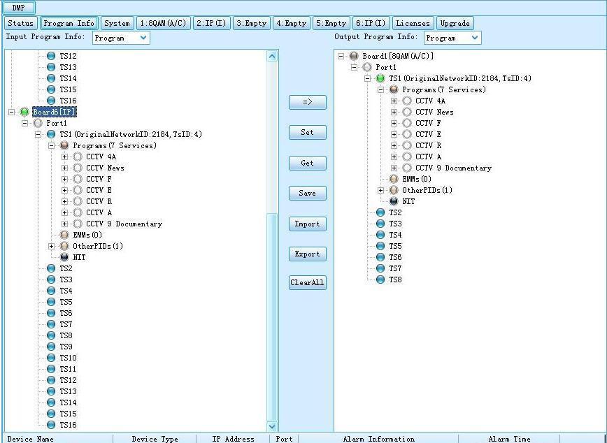
38 Yellow: the total output bit rate; Green: the effective output bit rate; Red: alarm indicator, it means the actual output bit rate (it s proportional to the amount of the programs you transfer from input port to output port in Program Info ) is more than the output bit rate of some channel you set in sub-board 2. Communicate Status indicates the communication status between NMS and DMP900 equipment. Green: the communication is normal. All the parameters in NMS are updated according to DMP900 synchronously. Red: the communication is abnormal. The parameters in NMS maybe not updated in time. You need check the network connection and restart the NMS. Program Info: this menu is to configure the input and output program of the DMP. 38 / 116


39 1 Input Program Configuration 3 Operation Buttons 2 Output Program Configuration 1 Input Program Configuration: the Input Program Configuration is on the left side of the Program Info window. It displays all the inserted modules information and the received input streams. 4XDVB-S2 Module inserted in Slot 1 Port 1 & 2 of DVB-S2 module are 39 / 116


40 Board1~6 represents the corresponding slots of the DMP. If the slot is inserted with a card module, the corresponding Board No. will be displayed on the Input Program Configuration window, and the name of the inserted module will be displayed after the Board No. For empty slot, no Board No. will be displayed. Port No.: represents each physical port of the inserted module. Scan the input TS: after the parameters of the inserted module are properly configured (refer to Chapter of this manual), select one port which is connected with input stream, and then click the mouse right button and select Scan TS menu. All the input stream of that port will be scanned and displayed. Scan the port that is fed with input stream Scan completes and receives data 40 / 116

41 2 Output Program Configuration: In the Output Program Configuration window, it shows the inserted module which can be set to transmit output stream. These kinds of modules include the Gigabit IP module, ASI module, 8-QAM and 4-OFDM module, etc. Settings on the Output Program please refer to Chapter of this manual. 3 Operation Buttons: the operation buttons include 4 different function buttons: Transfer button: to transfer the selected stream/pid from the input program window to the output program window. Set button: to apply the changes to the NMS. The setting will lose if the NMS is close or DMP is powered off. 41 / 116

42 To obtain/refresh the current parameters status of the DMP mainboard. To save the configuration. The saved data can be kept after NMS is closed or DMP power off. Import a configuration file. file. Export the current settings of the DMP and save as a configuration To eliminate all the settings in the input and output window. System: the System setting provides the system information of the DMP mainboard and inserted modules, including the mainboard IP address, Subnet Mask, Gateway, Trap IP address, MAC address and hardware/software version of each module. 42 / 116
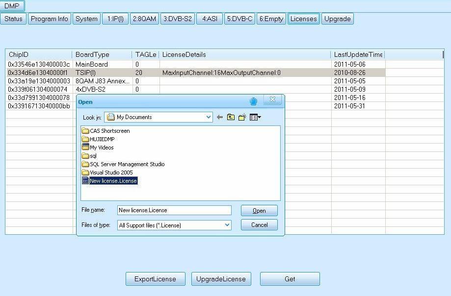
43 License: Wellav DMP provides very flexible license management on its modules. User can purchase new license to expand the module capability along with the business development, e.g. to update the license of a QAM module to let it support more channel output. License update procedure: Select License tab in the NMS. In the License main interface, select a module which you want to update the license. Click ExportLicense button to save the license file of the selected module, e.g. to export the old license as license backup.license 43 / 116

44 Send the license file license backup.license to Wellav for an updated license. Select UpgradeLicense button to import the new license file from Wellav. 44 / 116
45 45 / 116

46 License update succeeds. Upgrade: In the Upgrade tab, user can upgrade the software version of the DMP mainboard and its module components. The upgrade usually is either to fix any bug or implement new features. Improper upgrade operation might damage the DMP. Contact your service provider before the upgrade. Make sure the network connection and power supply is in good condition before the upgrade. NEVER TURN OFF THE DMP, CUT OFF THE POWER SUPPLY OR UNPLUG ANY MODULAR CARD DURING THE UPGRADE. Standard upgrade procedures: Select Upgrade tab and open the Upgrade interface; 46 / 116


47 Click Select File button to open the upgrade files; After selecting the upgrade file, the upgrade file will be listed in the Optional window. Click the button to transfer the upgrade file from the left Optional window to the right Selected window. 47 / 116


48 Note: 1. For some sub-modules upgrade, the upgrade files will be automatically put into the Selected window after selecting the file. 2. To unselect the upgrade file, double click the left mouse button on the selected file to remove it from the selected list. Click the Start button to start the upgrade. The upgrade process can be monitored in the Send Progress bar, Write Flash Progress bars and the Info window. A notifying window shows up after successful upgrade. 48 / 116

49 3.1.4 Parameters Setting of the Sub-module In accordance with the 6 modular slots of the DMP, there are total 6 module parameters setting tabs in the configuration menu. Each tab represents the corresponding slot of the DMP. Each tab displays the name of the inserted module. If the slot is empty, then the tab shows Empty as well. It is of great importance to correctly set the parameters of each module so that the DMP can work properly. Please go through this section for the module setting details before operating the DMP. DVB-C Receiving Module The DVB-C module supports receiving programs compliant with DVB-C standard from 4 different frequencies simultaneously. 4-DVB-C Receiving Module The config page of this module includes two parts: Status: indicates the basic parameter and locking status of input signal. 49 / 116

 Total Rate Indicates the total bit rate of input signal, including the valid and null packet.")
50 Setting: set the parameters for receiving the input signal. After setting all parameters, you should press the Set button to save the settings. Status The parameters of this part are derived from the input signal; they will be gotten automatically when the input signal is available, and cannot be changed by the user. Introduction to the parameters of Status Parameters Description Port Indicates which input port the channel comes from. Status Indicates whether the input signal is LOCK) or UNLOCK. Size Indicates the packet size within the input TS stream. (188 or 204) Total Rate Indicates the total bit rate of input signal, including the valid and null packet. The unit is Mbps Effective Rate Indicates the bit rate of valid packet (excluding the null packet). The unit is Mbps. Signal Strength Indicates the strength of input signal Signal Quality Indicates the quality of input signal Setting In order to receive the input signal successfully, it s important to set the correct parameters 50 / 116


51 in the setting menu. The key parameters of a received channel include Frequency, Symbol Rate, and QAM Mode. Parameters Port Frequency Symbol Rate QAM Mode Description Indicates which input port the channel comes from. Frequency on which the channel is transmitted. The unit is in KHz. Symbol rate of the input channel. The unit is in KS/s. Select the actual QAM mode of the input channel. Note: the input signals of Port 1&2 are from the RF-IN 1/2 port of tuner 1, and the input signals of Port 3&4 are from the RF-IN 3/4 port of tuner 2. Please contact your program provider for the parameters details of the channel if you are not clear about. DVB-S/S2 Receiving Module The DVB-S/S2 module supports receiving programs compliant with DVB-S or DVB-S2 standard from 4 different frequencies (transponders) simultaneously. The config page of this module includes two parts: Status: indicates the basic parameter and locking status of input signal. Setting: set the parameters for receiving the input signal. After setting all parameters, you should press Set button to save the settings. 51 / 116
 or UNLOCK.")
. The unit is Mbps. Mode Indicates which standard the input signal is, DVB-S or DVB-S2.")
52 Status The parameters of this part are derived from the input signal; they will be gotten automatically when the input signal is available, and cannot be changed by user. Introduction to the parameters of Status Parameters Description Port Indicates which input port the channel comes from. Status Indicates whether the input signal is LOCK) or UNLOCK. Size Indicates the packet size within the input TS stream. (188 or 204) Total Rate Indicates the total bit rate of input signal, including the valid and null packet. The unit is Mbps Effective Rate Indicates the bit rate of valid packet (excluding the null packet). The unit is Mbps. Mode Indicates which standard the input signal is, DVB-S or DVB-S2. FEC CodeRate Indicates the code rate which is used in FEC. C/N Indicates the real-time carrier to noise ratio. BER Indicates the real-time bit error rate. 52 / 116

53 Constellation Center Frequency Indicates the constellation used in the input signal. Indicates the center frequency from the transponder. The unit is MHz. Setting In order to receive the input signal successfully, it s important to set the correct parameters in the setting menu. Parameters of the Setting menu: Parameters Port SatFrequency SymbolRate Polarization BandSelection Type LOLowfrequency LOHighFrequency Bias Description Indicates which input port the channel comes from. Input the frequency of transponder which you want to receive programs from. The unit is MHz. Input the symbol rate of the transponder. The unit is KS/s. Select the voltage provided to LNB (13V for vertical or 18V for Horizontal). Select the band of LNB you want to use, including Auto, Forced Low and Forced High. Select the actual type of your LNB, Single Band or Dual Band. The low frequency of LNB. The unit is MHz. The high frequency of LNB. The unit is MHz. Enable or disenable the polarization setting. Note: 1. Parameters of FECCodeRate can be automatically recognized by the NMS; 2. Only LNB 1 & 3 inputs support polarization setting. LNB 2 & 4 cannot provide power (13V or 18V) to the LNB. DVB-ASI I/O Module The ASI module is equipped with four BNC-type ASI connectors, supporting four ASI input/output. The default setting of the module is: Ports 1 & 2 is for input, and Ports 3 & 4 is for output. User can specify the port to be input or output at any time through the NMS. 53 / 116
 MinRate(Mbit) Description Set each ASI port to be Input or Output. Set 188 or 204 packet size for outputs.")

54 Settings in the ASI module NMS The key parameters in this NMS interface include: Parameters Type PacketSize Mode ConstantRate(Mbit) MaxRate(Mbit) MinRate(Mbit) Description Set each ASI port to be Input or Output. Set 188 or 204 packet size for outputs. Set ASI port into CBR or VBR for output. Set constant bitrate for ASI output. Set max bitrate for ASI output. Set min bitrate for ASI output. Note: For the input parameters, it is automatically obtained by the NMS when connected with the input signal. It is in not editable status. 54 / 116


55 Gigabit IP I/O Module The IP module is equipped with two RJ45 connectors. One is for the IP stream input/output; the other is for stream output only, it s as the backup output when you set TS/IP port as output mode. The configuration of the IP module can be done through its NMS. IP Module Setting Interface By selecting the IP tab on the DMP NMS operation interface, the IP module setting interface will be displayed. The settings on the IP module include the settings on the Receiver, Transmitter and System. System Setting of the IP I/O Module 55 / 116

56 In the System setting menu, user need to set correct parameters for the IP module such as the IP address, subnet Mask, Gateway, etc, so that the module can work normally in the network. Parameters IP Address Subnet Mask Gateway MAC Address SpeedMode IGMP Version Description Set IP address of IP module. The IP address of IP module is used for communication with basic unit of DMP that should be in the same IP section with IP address of DMP. Set Subnet Mark of the IP module Set Gateway of the IP module MAC address of the IP module Set RJ45 connection speed mode. The speed mode support 100Mbit and 1000Mbit. Set IGMP Version for multicast. The IGMP version setting should match the IGMP version of the switch in the network. Receiver Setting The Receiver setting menu is to set the IP input function for receiving multicast/unicast IP stream. 56 / 116

57 Parameters ChannelSelect Enable Channel configuration EnableChannel SourceIPAddress SourcePort Protocol ColPortMatching RowPortMatching FEC Parameter Description In this ChannelSelect, user can select a channel to configure its parameters. On: enable the IP receiving function. Off: disable the IP receiving function. Note: this parameter setting applies to all channels. Enable or disable corresponding input channel Set the IP address of the multicast/unicast that are going to receive Set port of multicast/unicast Select UDP/RTP for multicast/unicast If the output IP stream quality looks not as good as the input stream, user can select to Enable these two options then to enable the FEC function. The bigger values it is, the stronger capabilities it has to correct the data mistakes. But the FECL and FECD should be less than 100. After setting all the parameters, you should press Set button to save the settings. Transmitter Setting The Transmitter setting menu is to set the IP output function for transmitting multicast/unicast IP stream to other devices. 57 / 116
58 Parameters ChannelSelect Enable Channel configuration EnableChannel SourcePort DestIPAddress Protocol EncapNumTSPackets TSPacketSize TypeofService Time To Live EnableVLAN VLAN ID FEC Parameter EnableFEC ColFECOnly InterleaveMode FECL FECD Bitrate Parameter Mode ConstantRate(Mbit) MaxRate(Mbit) MainRate(Mbit) Description In this ChannelSelect, user can select a channel to configure its transmitting parameters. On: enable the IP receiving function. Off: disable the IP receiving function. Note: this parameter setting applies to all channels. Enable or disable corresponding output channel Set port of multicast/unicast Set IP address of the multicast/unicast. Select UDP/RTP for multicast/unicast Rang 1~7. (Num 7 is recommended) Select 188/204 TS packet size Select one service type as your requirement. Type including: Normal, Min delay, Monetary cost, Max reliability, Max Throughput. Range is (Num 8 is recommended) Enable/Disable VLAN. Set VLAN ID. Enable/Disable FEC Yes for only Col FEC, no for Col&Row FEC Mode includes: Annex_a, Annex_b and Off The bigger values it is, the stronger capabilities it has to correct the data mistakes. But the FECL and FECD should be less than 100. Mode includes: CBR/VBR Set constant bitrate for output Set max bitrate for output Set min bitrate for output 8-QAM/4-COFDM Module The 8-QAM/4-COFDM module can output up to 8 separate RF QAM frequencies signals with its physical output interface. With adopting corresponding license key, the module can turn to a 4-COFDM module without changing the hardware. 58 / 116

59 8-QAM/4-COFDM module NMS configuration interface: Parameters Bandwidth RF Level SymbolRate (Channel 1~4) SymbolRate (Channel 5~8) Enable RF Frequency (KHz) Mode MaxRate ActualRate Description Select the bandwidth of output RF, 6M/7M/8M are available. Set RF output signal level in dbu, the value RF Level is 90dBu~115dBu Set symbol rate for the first four transmission frequencies Set symbol rate for the last four transmission frequencies Switch Enable or Disable for the selected channel output Set the carrier frequency for the first modulation frequency. Note: for the RF frequencies of port 2~8, they will be set automatically by the NMS base on the frequency of port 1 and the Bandwidth setting. Set modulation type of each modulators port. The modulation mode can be QAM16, QAM32, QAM64, QAM128, QAM256. The maxrate is automatically calculated by the NMS according to the QAM mode the user selects. The actualrate set by the user shall not exceed the maxrate to ensure best signal quality. The bitrate user set for the output. It is set by the user in other related sub-module such as the encoding module. 59 / 116

60 CI Descrambling Module The CI descrambling module is for descrambling the input scrambled stream via CAM module. The module supports 2 CAMs working simultaneously. In the CI module NMS interface, there are four items for user to select/configure. Only after the parameters are correctly set can the CI module work normally. Parameters CAM No. Enable/Disable switch TSClock Description Indicates which CAM the user is operating. Enable--turn on the CI module and enable the input stream to pass through the CI module and get descrambled. Disable--Disable any input stream to pass through the CI module and thus the CI module will not be functional.!please select Disable if no CAM is inserted in the CI module. The TSClock is selected according to the CAM and actual bitrate of input TS. Five options in the TSClock can be selected: 9MHz--support up to 72Mbit input TS. 9.5MHz--support up to 76Mbit input TS. 10.5MHz--support up to 84Mbit input TS. 11.5MHz--support up to 92Mbit input TS. 13MHz--support up to 104Mbit input TS.! Please select default 9MHz for the TSClock if input TS is less than 72Mbit in total bitrate. And usually a standard CAM can support Max. 72Mbit data processing unless it has 60 / 116

61 Mode ConstantRate (Mbit) instruction for higher bitrate support. Selecting a wrong CAM output bitrate will cause video mosaic issue because the actual processed data exceeds the CAM Max. handling capability. CBR--the output descrambling TS bitrate is set at a bitrate which set in the ConstantRate. VBR--the output descrambling TS bitrate is changeable depending on the input TS. To set a fixed output bitrate for the CI module. It will take effect when user selects the CBR mode.!please set a bigger bitrate value than the input TS rate and reserve a bit buffer. Note: for the descrambling operation on a program, please refer to Descramble Operation, page-51 of this manual for the details. 2-SD&HD H.264 SDI/AV Encoder Module The 2-SD&HD H.264 SDI/AV Encoder Module supports encoding 2 SDI channels or 2 AV channels simultaneously. Settings in the Encoder module NMS 61 / 116

62 Introduction to the parameters in this NMS: Parameters Channel Video Source Audio Source Video Max Encode Rate Video Min Encode Rate Video Encode Rate Audio Encode Rate Encode Rate GOP Struct Encode Mode Video PID Audio PID PCR PID PMT PID Program Number Transport Stream ID Provider Name Program Name Frame Rate Description Indicates which input port the channel comes from. To select the correct video source for the input. To select the correct audio source for the input. To set the Max. encode rate for VBR mode. To set the Min. encode rate for VBR mode. To set the encode rate for CBR mode. To choose the encoding bitrate for the audio. The total encode rate of video and audio contents. Calculated automatically by the software. To select GOP structure. Select CBR or VBR for the encoding mode. To edit the video PID. To edit the audio PID. To edit the PCR PID. To edit the PMT PID. To edit the program number. To edit the transport stream ID. To edit the program provider name. To edit the program name. To select correct frame rate according to the input source. 62 / 116
63 1GB Scrambling Module Insert the scrambler module to a DMP empty slot, and select the Scrambler tab on the NMS to enter the scrambler configuration window: CAChannel: the scrambler module supports up to 4 CAS Simulcrypt. User can configure different settings for each CAS system by select different CAChannel in this item. 63 / 116

64 To ensure the scrambler module can set up connection successfully with the CAS server, user shall configure the correct parameters on the scrambler module IP Setting button: Click this button to set a IP address for the scrambler module per the network environment. 64 / 116

65 Other key parameters settings on the scrambler module: Each CAS system has a unique SystemID when it is registered in SystemID DVB. Please contact your CAS service provider if you don t know what the ID is. ECMGIPAddress Input the CAS server IP address. ECMGIPPort EMMGTCPPort EMMGUDPPort EMMPID EMMChannelID EMMStreamID EMMDataID Shall input the same port no and ID setting as those on the CAS server. Otherwise connection cannot be set up between the CAS server and the scrambler module. After inputting the correct parameters, the scrambler module shall connect successfully with the CAS server. Next is to add the AC Data for each program of a TS stream. Click Add button on the NMS 65 / 116
, and click Add to insert the AC Data.")
66 In the Add ECM window, input the ACData (Hex), and click Add to insert the AC Data. 66 / 116
 for")
67 After finishing all the parameters setting and the AC Data insertion, click Set button on the NMS to apply for the settings. After configuring on the scrambler module setting window, user shall operate in the Program Info tab to specify which program to be scrambled and transfer to the transmission module (QAM/IP/ASI) for output. Operation steps are as following: Select the program which is to be scrambled and transfer it from the signal source to the scrambler module at Output Program Info. (To know how to transfer programs, please refer to chapter 3.1.5) In below example picture, program FujianTV1 is selected and is transferred from DVB-S2 module in Input Program Info window to scrambler module in Output Program Info window. 67 / 116

68 Edit the Network ID, TsID for the selected program, same as the setting in the CAS server for that program. Select the program name and click mouse right button to select Scramble Setting. 68 / 116


69 In the Scrambler Setting window, select an AC Data we previously input and click OK to bond with the selected program. 69 / 116

70 After the program is scrambled, the button indicators of the program name will turn to black color. The scrambling program stream will be automatically transferred to the Scrambler module in the Input Program Info window for transmission. Select the program we just scramble in the Scrambler module in Input Program Info window, and transfer it to any transmission module. The output program is already scrambled. 70 / 116

71 TC2 & TC4 Transcoder Module Introduction to the parameters on this module NMS: Parameters Channel Transcoder Type Description The channel quantity represents the supported max. transcoding channels. For 2-channel transcoding module, channel1~channel2 are available in this option, while channel1~channel4 are available for 4-channel module. Each channel transcoding parameters can be set in separated pages when selecting different channel. The transcoder module type is automatically recognized by the software and not selectable. ->H.264: Means the inserted module is a TC4 module (MPEG-2 to MPEG-4/H.264); ->MPEG-2: represents the inserted module is a TC2 module 71 / 116
72 Video Encode Mode (TC4 only) Audio Mode (TC2 only) Video Encode Rate Audio Encode Rate Encode Rate (Total) Volume (0~49) Video Standard (TC2 only) Video Max. Encode Rate Video Min. Encode Rate GOP Size (TC2 only) GOP Structure Aspect Ration Conversion Output Video Resolution (TC4 only) (MPEG-4 to MPEG-2) CBR: Constant Bitrate. The bitrate is fixed at the bitrate set in the Video Encode Rate option. VBR: Variable Bitrate. The bitrate is floating between the Maximum and Minimum bitrate range defined by the Max. and Min. Encode rate options. Select different audio encoding mode for the program. Set the encoded video bitrate, range from 1.0 to 20.0Mpbs Set the encoded audio bitrate, range from 64 to 384Kpbs Total bitrate automatically by the software which is not editable. The bitrate is summed up by audio and video bitrate. Define the output channel volume after transcoding. Level 0 means mute while level 49 is the Max. volume output. Select from PAL or NTSC. This parameter takes effect only when the Video Encode Mode is set to VBR on TC4 module. Max. Encode Rate: base on the parameter set in Video Encode Rate, it should be input a parameter from 1.75 to 2 times the encode rate. This parameter takes effect only when the Video Encode Mode is set to VBR on TC4 module. Min. Encode Rate: base on the parameter set in Video Encode Rate, it should be input a parameter from 0 to 0.75 times the encode rate. Base on the GOP structure definition and bandwidth to input an appropriate parameter. Base on the bandwidth and requirement on the video quality to select the appropriate GOP structure. Options are available for 4:3 and 16:9 aspect ratio. A list of video resolution can be selected for output video: 1920x1080 (60p/59.94p/30p/24p/60i/59.94i/50i); 1280x720 (60p/59.94p/50p); 720x480 (60i); 720x576 (50i) 72 / 116
")

73 Parameters setting page of NMS (TC2) Parameters setting page of NMS (TC4) 73 / 116
74 3.1.5 Program Input and Output Operation Note: the proper functionality of the DMP input/output depends on the correct settings of each inserted module. Please refer to Chapter to set up the parameters of each module before taking the Input/Output setting of the DMP. Click Program Info tab on the NMS to enter the configuration interface. Input Program Configuration This operation step is to get the input signal information on the inserted module. Please refer to Chapter 3.1.3, 1 Input Program Configuration of this manual for the operation details. Output Program Configuration Basic Configuration In the Output Program Configuration window, it shows the inserted module which can be set to transmit output stream. These kinds of modules include the Gigabit IP module, ASI module, 8-QAM and 4-OFDM module, etc. The operations on these modules are all the same. Operation Procedures Select the module which you want to transmit the output stream. 74 / 116
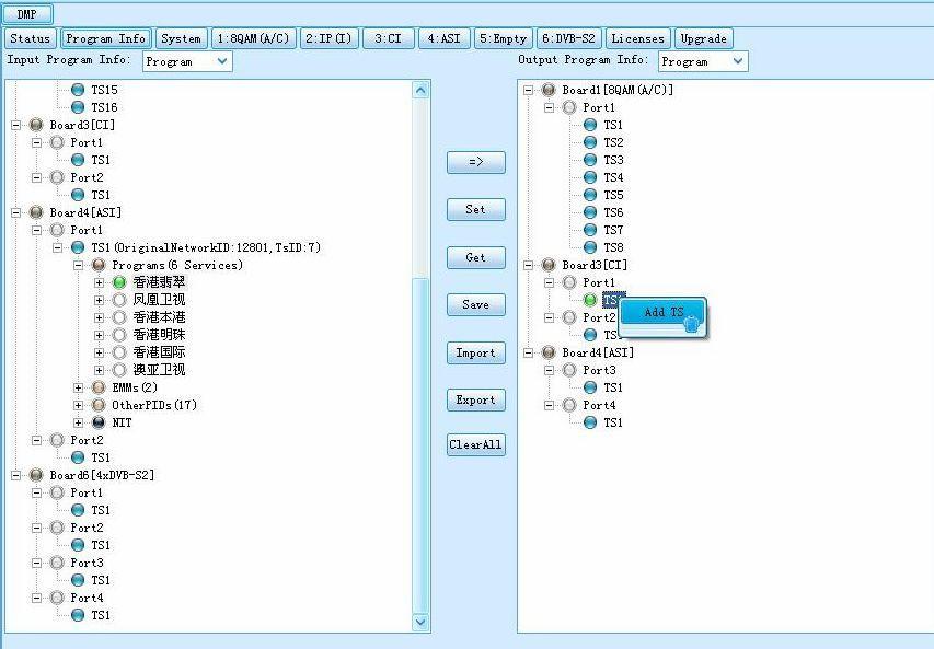
 to output the stream, and then click the right mouse button to choose Add TS. Input the Original Network ID and TS ID for the channel, and click the Add button.")
75 Name of the module The port number depends on the Physical interface of the module The TS number depends on the channel output capability of the module Select which TS (Channel) to output the stream, and then click the right mouse button to choose Add TS. Input the Original Network ID and TS ID for the channel, and click the Add button. 75 / 116
 name when it is being selected.")

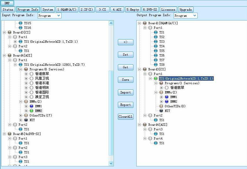
76 The input Original Network ID and TS ID will be assigned to the selected output TS (channel). To change the Original Network ID and TS ID, use the left mouse button to click the TS (channel) name when it is being selected. Then the TS (channel) name will be in editable status. To delete the inserted Original Network ID and TS ID, click the right mouse button on the TS, and select Delete. Select TS which is going to be transmitted on the left hand side Input Program Info window, and select the port, TS (channel) which are going to carry the transmission on the right hand side Output Program Info window. 76 / 116


77 Click the button to set transfer of the selected TS from the Input Program Info to the Output Program Info. Follow the save operation steps, user can set the selected input stream to be transmitted at any assigned output TS (channel). 77 / 116
 name when it is being selected.")
 Name PID Edit Click the + symbol under the channel name,")
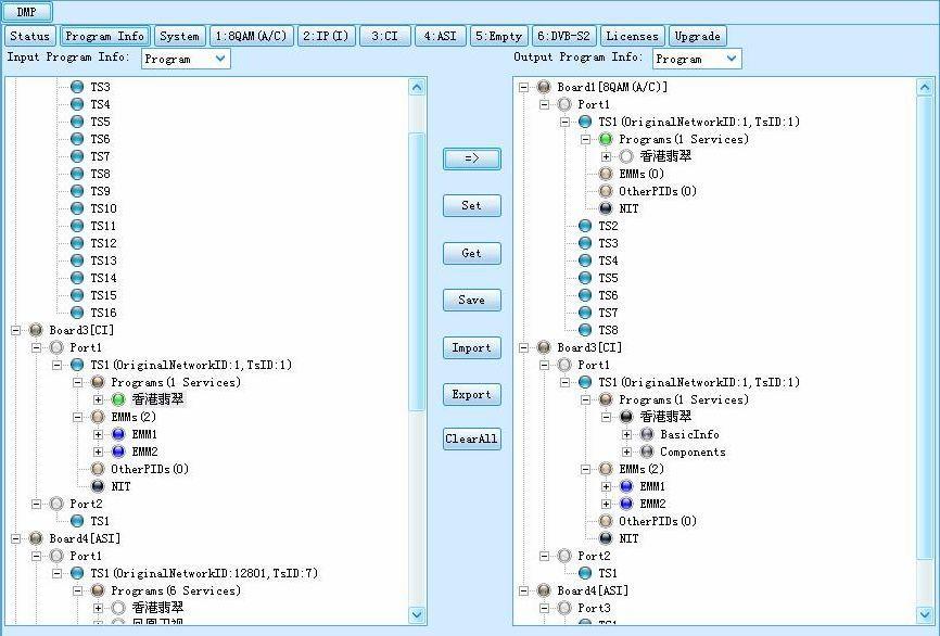
78 Advanced Configuration Channel Name Edit To change the Channel Name, use the left mouse button to click the TS (channel) name when it is being selected. Then the TS (channel) name will be in editable status. Select and change the TS (Channel) Name PID Edit Click the + symbol under the channel name, then all the elements of that channel will be expanded and displayed. 78 / 116
79 All the elements of the channel are editable. The edit shall be compliant with the related regulation of DVB. Descramble Operation Note: 1. the descramble function needs the support of a CI descrambling module. 2. the inserted CAM should be able to support the CAS of the scrambling program. 3. User needs to have a valid authorized smart card (same CAS type as the scrambling program) to work with the CAM. Operation Procedure: Select a scrambling program of a receiving module in the input window and transfer it to the corresponding CI module port (port 1 or 2) in the output window. The EMM data of the scrambling program must be transferred at the same time. 79 / 116
80 80 / 116
81 81 / 116

82 Use the right mouse button to click on the transferred program, and select Descramble menu. To cancel the descrambling operation on a program, just use the right mouse button to click the descrambling program and select menu Non-descramble. After the program is scrambled, the button indicators of the program name will turn to black color. 82 / 116
. Click Set button to apply all the settings at the final step.")
83 Back to the input program window, the descrambled programs have already been automatically transferred to the corresponding port of the CI module and waiting for setting to output. Select the descrambled programs and transfer them to any transmission modules (IP/QAM/ASI). Click Set button to apply all the settings at the final step. Operation of program descrambling finish. 83 / 116
84 84 / 116

85 Transcoding Operation Operation procedures: Select programs in Input which need transcoding processing, and follow the output program operation procedure to transfer the selected programs to transcoder output port. Program transferred for transcoding Selected program Note: When a program is transferred to transcoder module for output, a list of digits will be shown at end of the selected program name, which represents the transcoding source/target module and port. The meanings of the number are: a) Selected programs in Input window: Program name (To: X.X.X) To: means this program has been selected to transcoding output, X.X.X represents the output module No., port No. and TS No. For example, Program1 (To: 1.1.1) means Program1 has been transferred to transcoding module which installed on DMP slot1, and set to Port1 and TS1 for output. b) Selected programs in Output window: 85 / 116
 means Program1 comes from module 4, port 4 and TS1. c) For 2-channel transcoding module, only 2 outputs are available at output option, which are Port1 and Port2.")
86 Program name (From: X.X.X) (From:X.X.X) represents the input source of the program. X.X.X represents the input module No., port No. and TS No. For example, Program1 (From: 4.4.1) means Program1 comes from module 4, port 4 and TS1. c) For 2-channel transcoding module, only 2 outputs are available at output option, which are Port1 and Port2. While for 4-channel transcoding module, Port1, Port2, Port3 and Port4 are available for output. After transferring to transcoding module output, the selected programs will be re-encoding and available at the Input->Transcoder module for output transmission. Output the transcoded programs to any DMP transmission modules (TS/IP, ASI, QAM modulator, etc.) for output, and then the transcoder output operation is done. Programs available after transcoding. Programs transferred to output for transmission. Data Insertion NIT Insertion 1. Connect DMP through NMS, and complete the configuration on the output module. Here take DMP 8QAM module as an example. The DMP 8QAM 8TS output is set at frequencies 474, 482, 490, 498, 506, 514, 522 and 530, SR / 116

87 2. Switch to Program Info tab to configure the output channels at each QAM channel. Here we output total 6 programs at 3 TS channels: CCTV-1, CCTV-2 and CCTV-7 at TS1; CCTV-11, CCTV-12 at TS2; CCTV-MUSIC at TS3 87 / 116
88 3. Select a TS channel, click mouse right button to enter the PSI/SI menu. We start with TS1 firstly. 88 / 116
89 4. PSI/SI menu interface. 5. Select NIT Actual, and use mouse right button to click and select Add NIT. 89 / 116
90 6. Input Network ID and Network Name for the new NIT to distinguish with other NIT, and click Ok to continue. 7. Under the new added NIT table, find the transport_stream item and use mouse right click on it to select Add NIT TS. 90 / 116
91 8. Input the Network ID and the TS ID. The ID must be same as that set in the output TS channel. Same as the ID set in the output TS channel 91 / 116

92 9. Under the new added transport_stream, find the item transport_descriptor, use mouse right button to select to add proper descriptor base on the actual situation. We select Add Cable Descriptor here because we use 8QAM module. 10. Input the TS1 channel parameter for the cable descriptor. (for the FEC_Inner option, please always select No.conv.coding ) 92 / 116

93 After input the descriptor, click Add, then user can expand the transport_descriptor menu to check whether the new added data correct or not. Then repeat steps 7~10 to add other frequencies to this NIT table. 11. After the configurations of the NIT, do remember to click Set and then Save button in the Program Info window to apply the settings. 93 / 116
94 If needed, you can right click Transport Description Descriptor Tag 0x44 cable delivery system descriptor to modify or delete the descriptor. LCN Insertion In telecommunications, a logical channel number (LCN), also known as virtual channel, is a channel designation which differs from that of the actual radio channel (or range of frequencies) on which the signal travels. The most common reason for a television station using a virtual channel is to minimize viewer confusion when a digital transmission is airing on a different channel from the one the station used in analog mode. The virtual channel thus enables viewers to tune in the station by choosing the same channel number as they would have previously. Wellav DMP supports LCN feature in a DTV system. Through following a few simple configuration steps then you can activate this feature. 1. Check out the service ID of each program under some TS. For example, we check the first TS- TS1, the service ID can be found under BasicInfo menu if expanding the + before each program. The service ID of the 6 test programs are: CCTV-1: 301 CCTV-2: 302 CCTV-7: 303 CCTV-10: 304 CCTV-11: 305 CCTV-12: 306 CCTV-MUSIC: / 116

95 2. Select TS1 channel, click mouse right button to enter the PSI/SI menu. 95 / 116
96 3. Enter NIT Actual Transport _Streams and then select transport_descriptor with mouse right button and select Add LCN Descriptor option. In the displayed operation window, input the service ID of the programs that transmitted in this channel, and the LCN that designated for this program. The visible_service_flag 96 / 116

97 please keeps using the default setting which is 1. After the setting, click Add to confirm the settings. 4. In the Program Info window to select other TS channel which need to edit PSI/SI, and follow the operation steps 1~3 to add LCN for each program in all TS. 5. After the settings on all output TS channel, do remember to click Set and then Save button in the Program Info window to apply the settings. 97 / 116
98 OTA descriptor Insertion To do the OTA upgrade for STB, generally you need insert an OTA descriptor into the NIT under the central frequency in head-end equipments. 1. Right click the TS which you set as central frequency TS and click PSI/SI. 2. Enter NIT Actual Network Descriptors and right click it and select Add network description. 3. Input the Tag and OTA descriptor and click Add 98 / 116

99 BAT Insertion If you need insert the BAT table in some frequency, you can simply following the steps as below: 1. Right click the TS where you want to insert the BAT and click PSI/SI. 2. Find BAT and right click it. Select Add BAT and then input the Bouquet ID and Name to create the BAT. 3. Right click Transport Stream under Bouquet Descriptor and click Add Bouquet TS. To delete the BAT, right click Bouquet ID x and then click Delete. 99 / 116


100 4. Input the Original Network ID and TS ID. 5. To add the service type for some program, right click Transport Descriptor under Transport stream id and then select Add service list descriptor. 100 / 116

101 6. Input service ID and select the service type from right part, and then click Add to add the service type for this program. You can also edit or delete the existing items by clicking Edit or Delete. 7. After adding the service type for all programs, click Exit to exit it. 101 / 116


102 8. To add other private descriptor, right click Transport Descriptor under Transport stream id and then select Add other descriptors. Input the Tag and Data in Hexadecimal and click Add. 102 / 116

103 SDT Descriptor Insertion To add the SDT descriptor, please go to Program Info of the NMS. 1. Find the program you want to add the SDT descriptor in and click + before SDT Info. Right click SDT Descriptors and then click Add Description. 2. Input the Tag and Data in hexadecimal, and click Add. 103 / 116

104 3. To delete the descriptor, right click the descriptor you added and click Delete Receiving Signal Auto- Backup Function The DMP900 supports auto-backup function for the receiving signals. Once the main receiving module breaks down, the backup module automatically takes over the signal receiving function to guarantee no signal lost happen in this case. This auto-backup function can be achieved on all DMP receiving module types, including DVB-S2 module, IP Input module and ASI module. To enable this function, user shall prepare 2 same type receiving modules, feed them with same signal sources, and assign Main / Backup for the two modules. The following we take the IP module setting as an example. Settings for the DVB-S2 and ASI modules are just the same. Insert two IP (Input) modules in slot 2 and slot 6 respectively. Feeding the two modules with same signal sources. 104 / 116
105 105 / 116
106 Mouse right click on the module name, and select Main or Backup for each module. As an example, here we set module in slot 2 as the Main module, and the one in slot 6 as the Backup module. After the setting, the modules will be marked with different color buttons in front of the module names for differentiation. 106 / 116

107 Click Set button to apply for the settings as the last step. 107 / 116
108 3.1.7 Configuration importation and exportation The backup configuration files of equipments are very important for the operator in actual application. It can help operator to restore all previous configuration quickly in case that DMP900 loses configuration or you need replace the current DMP900 due to any reason, so that the DMP900 can continue operating with less break time. Export and import the entire configuration of DMP900. It includes program list, the configuration of each sub-board. 1. Go to System and click Export. 2. Input the name of the backup file and click Save to save the entire configuration of DMP / 116

109 3. To import the backup file to DMP900, go to System and click Import. 4. Select the backup file and click Save. Then the file will be imported automatically. 109 / 116

110 Export and import the program list only. Go to Program Info and click Export or Import to export or import the program list. Export and import the configuration of one sub-board only. Go to the sub-board which you want to export configuration from or import configuration into, and click Export or Import to export or import the sub-board configuration. 3.2 Operation through Front Panel For some basic operation, such as checking the DMP and sub-board information, and working status, besides using the NMS, user can also operate via the front panel control buttons and menu. For detailed configuration on each module and advanced application, it is recommended to operate via NMS. 110 / 116
111 3.2.1 Front Panel Control Buttons 1. Navigation Keys: Up/Down/Left/Right buttons. Used for moving the cursor during the operation Menu: o Enter a menu or Return to previous/upper level menu. 3. OK: to confirm the edit in the menu. 111 / 116

112 3.2.2 Front Panel Operation Menu Structure 112 / 116
Simple Media Platform Quick Installation Guide V1.0-N. Simple Media Platform. Quick Installation Guide
 Simple Media Platform Quick Installation Guide 1. Installation Instruction 1.1 Mounting unit to a 19 rack When selecting the installation site, try to comply with the following: Protective Ground - The
Z-IP Stream 004/008. User Guide and Installation Manual. Four or Eight Input QAM Encoder / Modulator
 Z-IP Stream 004/008 User Guide and Installation Manual Four or Eight Input QAM Encoder / Modulator MPEG-2 / H.264 HD ENCODER with QAM /IP/ & ASI Outputs Contents Safety Precautions... 3 Package Contents...
UMH160 Integrated Digital Receiver Quick Installation Guide
 UMH160 Integrated Digital Receiver Quick Installation Guide Wellav Technologies Ltd. 1 Preface About This Document This document provides introductions and guidelines to users about how to install and
AES/EOU R-AUDIO2 R-AUDIO1 L-AUDIO1 L-AUDIO2 CVBS CVBS OUT R-AUDIO1 R-AUDIO2 ASI OUT2 GPI/LS DATA
 160R-Base R-AUDIO1 R-AUDIO2 AES/EOU ASI OUT RF OUT RF IN L-AUDIO1 L-AUDIO2 CVBS ASI IN GPI/LS DATA 160R-AD GPI/LS DATA CVBS OUT R-AUDIO1 R-AUDIO2 ASI OUT2 ASI IN2 RF OUT2 RF IN2 RF OUT1 RF IN1 Introduction
Professional HD Integrated Receiver Decoder
 Professional HD Integrated Receiver Decoder User Manual V1.00-C Preface About This Manual This manual provides introductions to users about how to operate the device correctly. The content includes introduction
Operation and Installation Guide
 Operation and Installation Guide HDS2800 Series Encoder Modulator High Definition (HD) Digital COFDM MPEG2 and H.264 Modulator with IP Multicast. 19 Rack Mount Revision 4.0 Firmware version Released File
HD Digital MPEG2 Encoder / QAM Modulator
 HD Digital MPEG2 Encoder / QAM Modulator HDMI In QAM Out series Get Going Guide ZvPro 800 Series is a one or two-channel unencrypted HDMI-to-QAM MPEG 2 Encoder / QAM Modulator, all in a compact package
AVE HOME FAGOR CVBS TO DVB-T ENCODER MODULATOR. Fagor Electr6nica
 AVE HOME CVBS TO DVB-T ENCODER MODULATOR FAGOR Fagor Electr6nica TABLE OF CONTENTS 1. SPECIFICATIONS... 12 1.1 Product Overview... 12 1.2 Appearance and Description... 12 1.3 Diagram... 13 1.4 Characteristics...
HD Digital MPEG2 Encoder / QAM Modulator
 HD Digital MPEG2 Encoder / QAM Modulator YPrPb VGA In QAM Out series Get Going Guide ZvPro 600 Series is a one or two-channel Component or VGA-to-QAM MPEG 2 Encoder/ Modulator, all in a compact package
Operation and Installation Guide
 Operation and Installation Guide HDS2800 Series Encoder Modulator High Definition (HD) Digital COFDM MPEG2 and H.264 Modulator with IP Multicast. 19 Rack Mount Wall Mount Revision 0.1 Firmware version
DM-1CH SD DVB-T MODULATOR INSTRUCTION MANUAL
 DM-1CH SD DVB-T MODULATOR INSTRUCTION MANUAL 2. Caution Statements and Table of Contents Table of Contents 2. Caution Statements and Table of contents 3. Important Safety Instructions 4. Important Safety
TV4U QUAD DVB-S2 to DVB-C TRANSMODULATOR
 INSTRUCTION MANUAL Features of the new DVB-C transmodulators line Through the use of the FPGA technology the transmodulators provides the highest performance at the lowest price. Four carriers are formed
HD Digital MPEG2 Encoder / QAM Modulator Get Going Guide
 series HD Digital MPEG2 Encoder / QAM Modulator Get Going Guide HDb2640 HDb2620 HDb2540 HDb2520 The HDbridge 2000 Series is a combination HD MPEG 2 Encoder and frequency-agile QAM Modulator, all in a 1RU
HD-1603 Single Input MPEG-4 DVB-T HD Encoder/Modulator User Guide and Install Manual
 ZyCastR digi-mod HD Range digi-mod HD-1603 www.digi-modbyzycast.com HD-1603 Single Input MPEG-4 DVB-T HD Encoder/Modulator User Guide and Install Manual Table of Contents www.digi-modbyzycast.com Safety
Digital CATV Head End Modular Bank
 Digital CATV Head End Modular Bank User Manual (ver. A) http://www.pbi-china.com 目录 1. SUMMARY...1 2. BASIC OPERATION ON HDMS...2 2.1 Minimum requirements for PC...2 2.2 Installation...2 2.3 Edit IP addresses
AMD-53-C TWIN MODULATOR / MULTIPLEXER AMD-53-C DVB-C MODULATOR / MULTIPLEXER INSTRUCTION MANUAL
 AMD-53-C DVB-C MODULATOR / MULTIPLEXER INSTRUCTION MANUAL HEADEND SYSTEM H.264 TRANSCODING_DVB-S2/CABLE/_TROPHY HEADEND is the most convient and versatile for digital multichannel satellite&cable solution.
7881IRDA Series QUICK START GUIDE
 7881IRDA Series QUICK START GUIDE Copyright 2013-2015 EVERTZ MICROSYSTEMS LTD. 5292 John Lucas Drive, Burlington, Ontario, Canada L7L 5Z9 Phone: +1 905-335-3700 Sales: sales@evertz.com Fax: +1 905-335-3573
HD Digital Set-Top Box Quick Start Guide
 HD Digital Set-Top Box Quick Start Guide Eagle Communications HD Digital Set-Top Box Important Safety Instructions WARNING TO REDUCE THE RISK OF FIRE OR ELECTRIC SHOCK, DO NOT EXPOSE THIS PRODUCT TO RAIN
DVB IP CONVERTER FOR IPTV HEADENDS with INTEGRATED RECEIVER & DECODER & REMUXER
 DVB IP CONVERTER FOR IPTV HEADENDS with INTEGRATED RECEIVER & DECODER & REMUXER PRODUCT DESCRIPTION The DMM-151/152 is a high-density, cost-effective modular DVB to IP gateway system and DVB streamer for
Evolution Digital HD Set-Top Box Important Safety Instructions
 Evolution Digital HD Set-Top Box Important Safety Instructions 1. Read these instructions. 2. Keep these instructions. 3. Heed all warnings. 4. Follow all instructions. 5. Do not use this apparatus near
CAUTION RISK OF ELECTRIC SHOCK NO NOT OPEN
 Evolution Digital HD Set-Top Box Important Safety Instructions 1. Read these instructions. 2. Keep these instructions. 3. Heed all warnings. 4. Follow all instructions. 5. Do not use this apparatus near
Check our knowledge base at
 USER MANUAL Check our knowledge base at www.paralinx.net/support Copyright 2015 Paralinx LLC All Rights Reserved TABLE OF CONTENTS 1 Important Notice 10 LCD Screen 2 Safety Instructions 11 Indicators 3
DVB IP CONVERTER FOR IPTV HEADENDS with INTEGRATED RECEIVER & DECODER & REMUXER
 DVB IP CONVERTER FOR IPTV HEADENDS with INTEGRATED RECEIVER & DECODER & REMUXER PRODUCT DESCRIPTION The DMM-151 is a high-density, cost-effective modular DVB to IP gateway system and DVB streamer for IPTV
Common Media Platform
 CMP100 Common Media Platform Introduction Remote Network Management Unified Access to the Signal 4RU High Density Design Dual Power Supply 16 Hot-Swappable Modules N+1 Input Backup 1+1 Output Backup Introduction
Table of Contents. 1. Safety Use. 2. General Description. 3. Connection Diagram. 4. Operations and Management. 4.1 Display Status. 4.
 DTM-HD01 Thank you for buying this encoder modulator. Please read this manual carefully to install, use and maintain the encoder modulator in the best conditions of performance. Keep this manual for future
HD-1600 Single Input MPEG-4 DVB-T HD Encoder/Modulator User Guide and Install Manual
 digi-mod HD Range digi-mod HD-1600 www.resi-linx.com HD-1600 Single Input MPEG-4 DVB-T HD Encoder/Modulator User Guide and Install Manual Table of Contents Safety Precautions 2 Package Contents 2 Product
SD4650 DVB-T HD MODULATOR. User Manual
 SD4650 DVB-T HD MODULATOR User Manual 0 TABLE OF CONTENT 1 GENERAL...2 1.1 Description...2 1.2 Specifications...3 2 INSTALLATION...4 2.1 What s in the Box...4 One power cable...4 2.2 Connection...4 2.2.1
MediaKind RX
 MediaKind RX8330 The MediaKind RX8330 Distribution Receiver provides feature-rich multi-format standard definition decoding capability with high quality SDI output for video distribution applications.
User s Manual HDMI Modulator ATSC 8VSB/QAM 65/256. Model No : HDM100
 User s Manual HDMI Modulator ATSC 8VSB/QAM 65/256 Model No : HDM100 Contents 1. Safety Instructions & Precautions. 1 2. Operation Guide.. 2 2-1. Connection Diagram. 2 2-2. Front Panel.... 3 2-3. Rear Panel.....
HD168Bi Quad CVBS/HDMI HD DVBT Encoder Modulator U S E R M A N U A L
 HD168Bi Quad CVBS/HDMI HD DVBT Encoder Modulator U S E R M A N U A L Contents 1. GENERAL 1.1 Description 1.2 Specifications 2. INSTALLATION 2.1 What s in the Box 2.2 Connection 2.2.1 DEVICE Programming
T3316 IP QAM Modulator User Manual
 T3316 IP QAM Modulator User Manual SW Version: 1.02 HW version: 0.70.0.0 Web NMS version: 1.02 Intended Audience About This Manual This user manual has been written to help people who have to use, to integrate
CompactMax-2 DVB-S/S2 TO DVB-T2 TRANSMODULATOR - 0 MI2100 -
 CompactMax-2 DVB-S/S2 TO DVB-T2 TRANSMODULATOR - 0 MI2100 - SAFETY NOTES Read the user s manual before using the equipment, mainly "SAFETY RULES" paragraph. The symbol on the equipment means "SEE USER
HD4112 Quad HDMI MPEG2 HD DVBT Encoder Modulator U S E R M A N U A L
 HD4112 Quad HDMI MPEG2 HD DVBT Encoder Modulator U S E R M A N U A L HD4112 Manual Rev 1 Contents 1. GENERAL 1.1 Description 1.2 Specifications 2. INSTALLATION 2.1 What s in the Box 2.2 Connection 2.2.1
User manual Transmodulators. Ref. 5103S/5103T/5103Q/5130
 User manual Transmodulators Ref. 5103S/5103T/5103Q/5130 Contents 1 Introduction 2 1.1 The ProQuad range................................ 2 1.2 Modular system solution.............................. 4 1.3
User guide. IP output module - Art. No A
 User guide IP output module - Art. No. 492072 891080A GB Contents Contents Disposal... 3 Box content... 3 IP output module... 3 Labels... 4 Installation of IP modules... 5 Installation of extender boards...
The first TV Smart Headend designed for Hospitality SOLUTIONS FOR IN-ROOM ENTERTAINMENT PROVIDERS AND INTEGRATORS
 The first TV Smart Headend designed for Hospitality SOLUTIONS FOR IN-ROOM ENTERTAINMENT PROVIDERS AND INTEGRATORS 1 FLOW IN...3 FLOW SEC...4 FLOW ENC...5 FLOW OUT...6 FLOW HUB...7 FLOW BASE...8 FLOW PSU...9
Professional 4-Channel DVB Receiver and Transmodulator Item: 5213
 IDLV-3440DM Professional 4-Channel DVB Receiver and Transmodulator Item: 5213 IDLV-3440DM integrates 4 DVB Receiver and Transmodulator in one 1U 19 chassis. It provides operators an ideal DTV headend setup
World Class Modular MPEG-4 Digital Headend. 10 IRD 7U Rack can deliver up to 150 Channels (FTA + PAY) 56 FTA with 2 Gigabit 5U Rack (300~600 channels)
 56 FTA with 2 Gigabit 5U Rack (300~600 channels)") Product Briefs 10 IRD Rack can deliver (FTA + PAY) We use Professional Digital Satellite receivers with ASI and input and output interfaces which offers real time professional receive, demodulation, and
Product Briefs 10 IRD Rack can deliver (FTA + PAY) We use Professional Digital Satellite receivers with ASI and input and output interfaces which offers real time professional receive, demodulation, and
Model#: IN-MDRI3MF. Hardware User Manual. 3MP Indoor Mini Dome with Basic WDR, Fixed lens. (PoE) Ver. 2013/02/04
 Ver. 2013/02/04") Model#: IN-MDRI3MF 3MP Indoor Mini Dome with Basic WDR, Fixed lens Hardware User Manual (PoE) Ver. 2013/02/04 Table of Contents 0. Precautions 3 1. Introduction 4 Package Contents... 4 Features and Benefits...
Model#: IN-MDRI3MF 3MP Indoor Mini Dome with Basic WDR, Fixed lens Hardware User Manual (PoE) Ver. 2013/02/04 Table of Contents 0. Precautions 3 1. Introduction 4 Package Contents... 4 Features and Benefits...
Register your product and get support at SDV5122/27. EN User manual
 Register your product and get support at www.philips.com/welcome SDV5122/27 User manual Contents 1 Important 4 Safety 4 Notice for USA 5 Notice for Canada 5 Recycling 6 English 2 Your SDV5122 7 Overview
DX3316 IP QAM Modulator User Manual
 DX3316 IP QAM Modulator User Manual SW Version: 1.02 HW version: 0.70.0.0 Web NMS version: 1.02 DEXIN DIGITAL TECHNOLOGY 20142014 CORP. LTD. Intended Audience About This Manual This user manual has been
Operating Instructions
 Operating Instructions SDI Input board Model No. AV-HS04M1 РУССКИЙ FRANÇAIS DEUTSCH ENGLISH ESPAÑOL ITALIANO Before operating this product, please read the instructions carefully and save this manual for
28 4K LED monitor. User Manual M284K
 28 4K LED monitor User Manual M284K CONTENTS Safety Information... 2 What s included..... 4 Getting Started....... 8 Troubleshooting.... 14 Specification.... 15 2 of 15 SAFETY INFORMATION Read these instructions
DVISm. DVISm - Mini Digital Video Insertion System. Quick Start Guide. Patent Pending
 DVISm Patent Pending DVISm - Mini Digital Video Insertion System Quick Start Guide Although every effort has been taken to ensure the accuracy of this document it may be necessary, without notice, to make
Digital Video Recorder
 Digital Video Recorder Quick Operation Guide UD.6L0202B0067A02 Thank you for purchasing our product. If there is any question or request, please do not hesitate to contact dealer. This manual is applicable
Installation & Operational Manual
 Radiant Communications Corporation 5001 Hadley Road South Plainfield NJ 07080 Tel (908) 757-7444 Fax (908) 757-8666 WWW.RCCFIBER.COM QRF5000M MDU ENCODER Installation & Operational Manual Rev.A2 1. Introduction
TV4U DVB-S2 to DVB-S2 TRANSMODULATOR
 TV4U to TRANSMODULATOR TV4U to TRANSMODULATOR INSTRUTION MANUAL TV4U to TRANSMODULATOR The main application of to transmodulator Experience of MVDS terrestrial broadcasting shows that carrier must be restored
Model#: IN-DI2MIRF 2MP Indoor Dome with True Day/Night, IR, Basic WDR, Fixed lens
 Model#: IN-DI2MIRF 2MP Indoor Dome with True Day/Night, IR, Basic WDR, Fixed lens Hardware User Manual (PoE) Ver.2013/01/17 Table of Contents 0. Precautions 3 1. Introduction 4 Package Contents...4 Features
Digital Tuner Streamer
 Digital Tuner Streamer This Manual Apply to the MTRX 4/8 Tuner To IPTV Systems On 8 Tuners Systems, The inputs are all assigned to the 8 Tuners Only and no asi Web-NMS Version: 1.03 Software: 1.00 Hardware:
MediaKind RX8200 SkyUK CA
 MediaKind RX8200 SkyUK CA Advanced Modular Receiver - SkyUK CA The MediaKind RX8200 Advanced Modular Receiver is the industry standard Integrated Receiver Decoder (IRD) for decoding content feeds. RX8200
Professional HD Integrated Receiver Decoder
 Professional HD Integrated Receiver Decoder GEOSATpro DSR-180ASI with 708CC User Manual V1.00-C For Support, call 888-483-4673 Preface About This Manual This manual provides introductions to users about
2.0 Wall Mount TV Soundbar Instruction Manual
 8010275 2.0 Wall Mount TV Soundbar Instruction Manual Read all of the instructions before using this soundbar and keep the manual in a safe place for future reference. Safety Information CA UT IO N RISK
 Register your product and get support at www.philips.com/welcome SWW1890 User manual Contents 1 Important 4 Safety 4 English 2 Your Philips Wireless HD Net Connect 5 What is in the box 5 3 Overview 6
QAM MODULATOR CI. 4 x DVB-S/S2/T/T2/C+CI 4 x DVB-T/C + IP. Operation Manual
 QAM MODULATOR CI 4 x DVB-S/S2/T/T2/C+CI 4 x DVB-T/C + IP Operation Manual 1 1. IMPORTANT SAFETY PRECAUTIONS INFORMATION READ THE FOLLOWING WARNINGS BEFORE YOU USE YOUR DEVICE WARNING The following safety
TP160 IRD. Professional HD Integrated Receiver Decoder User Manual V1.0RC
 TP160 IRD Professional HD Integrated Receiver Decoder User Manual V1.0RC Preface Symbols Definition For the symbols that might appear in this document, the meanings they represent are as the following:
SAT IF distribution system
 7. Technical specifications Type cs43 RF input frequency range pr. 50-350 MHz inputs number 4 level pr. 55...88 dbµv 60...93 dbµv symbol rate 3 45 Ms/s return loss/impedance > 0 db/75 Ω LNB powering/control
Network Video Decoder NVD-20. Contents
 Contents Warnings and Precautions... 4 Warranty... 5 Standard Warranty... 5 Two Year Warranty... 5 Disclaimer of Product & Services... 6 Disposal... 6 Packing List... 6 Product Overview... 7 Features...
DXI-800 DVB-S/S2/T to IP streamer User Manual
 DXI-800 DVB-S/S2/T to IP streamer User Manual 1. Purpose of use DXI-800 is HD compatible IP streamer designed for a processing satellite and terrestrial signals to data broadcast (IP) connected to Ethernet.
Single & Dual Input HD Digital DVB-T Modulators
 Radio Frequency Range Installation Diagram digi-mod HD-1000DM / HD-2000DM www.resi-linx.com Single & Dual Input HD Digital DVB-T Modulators ANT IN 1 2 3 4 AUX MOD RF IN TV OUTPUTS MOD RF IN (PWR/IR PASS)
Refs , HDTV ENCODER/MODULATOR - Dual Component to QAM HDTV ENCODER/MODULATOR - Dual Component to QAM (EAS) QUICK INSTALLATION GUIDE
 QUICK INSTALLATION GUIDE") Refs. 563801, 563811 EN (EAS) QUICK INSTALLATION GUIDE w w w. t e l e v e s. c o m Safety instructions Caution statements Product inspection - Inspect the equipment for shipping damage. Should any damage
Refs. 563801, 563811 EN (EAS) QUICK INSTALLATION GUIDE w w w. t e l e v e s. c o m Safety instructions Caution statements Product inspection - Inspect the equipment for shipping damage. Should any damage
User Manual. UNIVERSE Ref. 8600
 User Manual UNIVERSE Ref. 8600 No part of this manual may be copied, reproduced, transmitted, transcribed or translated into any language without permission. Unitron reserves the right to change the specifications
QAM HD Integrated Receiver Decoder with SDI/HDMI/ASI/IP Signal Outputs. User Manual B-IRD-HD-PRO-Q HD IRD
 QAM HD Integrated Receiver Decoder with SDI/HDMI/ASI/IP Signal Outputs User Manual B-IRD-HD-PRO-Q HD IRD DIRECTORY Chapter 1 Product Outline... 1 1.1 Outline... 1 1.2 Features... 1 1.3 Specifications...
user manual Colosseum 8500D
 user manual Colosseum 8500D No part of this manual may be copied, reproduced, transmitted, transcribed or translated into any language without permission. Unitron reserves the right to change the specifications
OWNER'S MANUAL MODEL: DTV-2000 STANDBY/ON
 OWNER'S MANUAL MODEL: DTV-2000 STANDBY/ON CH+ CH- TABLE OF CONTENTS SAFETY PRECAUTIONS IMPORTANT SAFETY INSTRUCTIONS and FEATURES ACCESSORIES and LOADING BATTERIES REMOTE CONTROL UNIT FRONT PANEL and REAR
4400 Modular Series with 8VSB Receiver
 4400 Modular Series with 8VSB Receiver Receive, Demux & Protect Broadcast Feeds with Automatic Failover Between Fiber & OTA Sources Receive and stream in IP, all major and minor channels from 8VSB broadcast
-TECH DIGITAL. Explore The High DefinitionWorld. Website: Hot Line: [US] USER MANUAL
![-TECH DIGITAL. Explore The High DefinitionWorld. Website: Hot Line: [US] USER MANUAL](/thumbs/80/80689593.jpg "-TECH DIGITAL. Explore The High DefinitionWorld. Website: Hot Line: [US] USER MANUAL") -TECH DIGITAL Explore The High DefinitionWorld Website: www.jtechdigital.com Hot Line: 1-888-610-2818[US] USER MANUAL J-Tech Digital ProAV H.264 Encoder/Decoder Many to Many HDMI Extender RoHS 1 Operating
-TECH DIGITAL Explore The High DefinitionWorld Website: www.jtechdigital.com Hot Line: 1-888-610-2818[US] USER MANUAL J-Tech Digital ProAV H.264 Encoder/Decoder Many to Many HDMI Extender RoHS 1 Operating
DIGICAST DTVANE. DMB-9020 HD Professional IRD OVERVIEW
 OVERVIEW Conforming to MPEG-2(MP@ML), DMB-9020 HD Professional IRD supports DVB-S2 Tuner standard, and adopts high-quality decoding of MPEG-2, MPEG-4, and H.264 in broadcast level. Its CI descrambling
DCP Internet DCP-1000AV SDI/HDMI/AES & XLR
 Digital TV Equipment System Digital Contents Processing Platform DCP-1000 brings a compact flexible solutions that allow the users to build or update the DTV or IPTV headend to meet a variety of requirements
ITV-EN460d MPEG-4 AVC Encoder
 ITV-EN460d MPEG-4 AVC Encoder The ITV-EN460d MPEG-4 AVC Encoder is a real time compression solution that delivers unrivalled HD and SD video quality. The solution provides operators with the most powerful,
4IN1 IP QAM Modulator USER S MANUAL
 4IN1 IP QAM Modulator USER S MANUAL Catalog 1. SAFETY INSTRUCTION... 1 2. SYSTEM DIAGRAM AND WORK PRINCIPLE... 1 2.1 SYSTEM DIAGRAM... 1 2.2 WORKING PRINCIPLE... 2 3 FEATURE... 3 4 SPECIFICATIONS... 4
User Manual. HDMI Modulator Ref & SW Release
 User Manual HDMI Modulator Ref. 8201 & 8202 SW 1.1.1.Release No part of this manual may be copied, reproduced, transmitted, transcribed or translated into any language without permission. Unitron reserves
QRF5000 MDU ENCODER. Data Sheet
 Radiant Communications Corporation 5001 Hadley Road South Plainfield NJ 07080 Tel (908) 757-7444 Fax (908) 757-8666 WWW.RCCFIBER.COM QRF5000 MDU ENCODER Data Sheet Version 1.1 1 Caution Verify proper grounding
 Register your product and get support at www.philips.com/welcome SWS3435S/27 SWS3435H/37 EN User manual Contents 1 Important 4 Safety 4 English 2 Your SWS3435 6 Overview 6 3 Installation 7 Connect the
DMOD1200MS. HDMI Modulator. User Manual PLEASE READ THE MANUAL COMPLETELY BEFORE USE V.17.09
 DMOD1200MS HDMI Modulator User Manual PLEASE READ THE MANUAL COMPLETELY BEFORE USE V.17.09 CONTENTS 1. INTRODUCTION 1.1. Product Description 1.2. Package Contents 1.3. Hardware Installation 1.4. Safety
MyM Pro 3S/6S Installation guide
 MyM Pro 3S/6S Installation guide CONTENT 1. Introduction 2. Unpacking the unit 3. Connections and indications 4. IP settings 5. Menus and settings web ui 5.1 Overview menu 5.2 Input settings 5.3 Output
CompactMax-4 DVB-S/S2 TO ISDB-T TRANSMODULATOR - 0 MI2101 -
 CompactMax-4 DVB-S/S2 TO ISDB-T TRANSMODULATOR - 0 MI2101 - SAFETY NOTES Read the user s manual before using the equipment, mainly "SAFETY RULES" paragraph. The symbol on the equipment means "SEE USER
Applications & Features of the SB- SDQM- 2130
 Applications & Features of the SB- SDQM- 2130 Retrofit Existing 12 in 1 Analog Head Ends Into Standard Definition QAM Analog to Digital in one easy step Allows insertion of operators scrambled programming
HDMI 5x1 Switch B-240-HDSWTCH-5X1 INSTALLATION MANUAL
 HDMI 5x1 Switch B-240-HDSWTCH-5X1 INSTALLATION MANUAL IMPORTANT SAFETY INSTRUCTIONS To reduce the risk of fire or electric shock, read and follow all instructions and warnings in this manual. Keep this
User Manual High Definition Digital Set Top Box DVBT9070 Please read this User Manual carefully to ensure proper use of this product and keep this man
 User Manual High Definition Digital Set Top Box DVBT9070 Please read this User Manual carefully to ensure proper use of this product and keep this manual for future reference. Important Safety Instructions
ATTACHING & REMOVING THE BASE
 TV53DB ATTACHING & REMOVING THE BASE 1. To install or remove the neck, screw in or remove the 4 screws indicated in the picture. 2. To install the base, place the display unit flat on a table. Afterwards
PD1600. Satellite Gateways. Media Distribution. Headend in a Box. Applications. Features
 Satellite Gateways Media Distribution Headend in a Box (front view) ATX s is an ultra-compact headend in a box for the secure delivery of cable, satellite & IPTV content to MDUs, headend in the sky (HITS)
IxStream Headend. Quick Guide - Begin working with the IxStream headend. IX-Streamer, rev 1.1
 IxStream Headend Quick Guide - Begin working with the IxStream headend IX-Streamer, rev 1.1 Introduction... 3 Example setup... 3 Access the headend... 4 Important Concepts... 5 Push Config... 5 EMM...
DTE-1000 MPEG2 SD ENCODER
 DTE-1000 MPEG2 SD ENCODER MPEG2 system with IP and ASI output Technical documentation/instruction set/software manual Composed by: Merkl Tamás, Körmendi Ferenc, Gyebnár Zoltán Teletechnika Ltd. 7th Edition
IMPORTANT SAFETY INSTRUCTIONS
 IMPORTANT SAFETY INSTRUCTIONS 1. Read, follow and keep these instructions safely. 2. Heed all warnings. 1. Do not use this apparatus near water. 2. Clean only with dry cloth. 3. Do not block any ventilation
MON8-1 1U 8-Channel Multi-Display Video Monitor
 MON8-1 1U 8-Channel Multi-Display Video Monitor with Eight Backlit 1.75" LCD Displays, Eight CVBS Video Inputs, and Eight Loop-through Outputs Document P/N 821568 Rev-A User Manual CONTENTS Title and Contents...
MyM-3S Micro Master. Installation Guide. English. design for TV
 MyM-3S Micro Master Installation Guide design for TV 1 CONTENT 1. Introduction 2. Unpacking the unit 3. Connections and indications 4. IP settings 5. Menus and settings 5.1 Overview menu 5.2 Input settings
Contents. Disclaimer of Product and Services
 Instruction Manual Contents FCC COMPLIANCE STATEMENT... 3 WARNINGS AND PRECAUTIONS... 3 WARRANTY... 4 STANDARD WARRANTY... 4 THREE YEAR WARRANTY... 4 DISPOSAL... 4 INTRODUCTION... 5 FEATURES... 5 GO KMU-100
MyM Pro T2 Installation guide
 MyM Pro T2 Installation guide CONTENT 1. Introduction 2. Unpacking the unit 3. Connections and indications 4. IP settings 5. Menus and settings web ui 5.1 Overview menu 5.2 Input settings 5.3 Output settings
MON8-1/SDI 1U 8-Channel SDI Digital Multi-Display Video Monitor
 MON8-1/SDI 1U 8-Channel SDI Digital Multi-Display Video Monitor (Document P/N 821626, Rev-A) with Eight Backlit 1.8" LCD Displays, Eight SDI Video Inputs, Eight SDI Re-Clocked Outputs, and Eight CVBS (Analog)
OmniHub CMP201 CMP203 INTRODUCTION
 OmniHub RESET Module Status 1 2 3 4 5 6 CMP201 OmniHub MGMT1 MGMT2 DATA1 DATA2 CMP201 Module Status 1 2 3 4 5 6 CMP203 RESET OUT OmniHub MGMT1 MGMT2 DATA1 DATA2 CMP203 INTRODUCTION OmniHub is a new generation
Table of Contents FCC COMPLIANCE STATEMENT... 4 WARNINGS AND PRECAUTIONS... 4 WARRANTY... 5 STANDARD WARRANTY... 5 TWO YEAR WARRANTY... 5 DISPOSAL...
 1 Table of Contents FCC COMPLIANCE STATEMENT... 4 WARNINGS AND PRECAUTIONS... 4 WARRANTY... 5 STANDARD WARRANTY... 5 TWO YEAR WARRANTY... 5 DISPOSAL... 6 1. INTRODUCTION... 7 FEATURES... 7 2. CONNECTIONS
DSR-7400 Series. Commercial Integrated Satellite Receiver/Transcoder. Highlights. Product Overview
 DSR-7400 Series Commercial Integrated Satellite Receiver/Transcoder Highlights DSR-7412 provides 24 transcoded output services (12 HD and 12 down-converted SD) DSR-7401 transcodes and down-converts up
ZXV10 B760H ZXV10 B760E RichMedia Box User Guide
 ZTE CORPORATION NO.55,Hi-techRoadSouth,ShenZhen,P.R.China Postcode:518057 Tel: (86) 755 26771900 800-9830-9830 Fax: (86) 755 26772236 URL: http://support.zte.com.cn E-mail: doc@zte.com.cn ZXV10 B760H ZXV10
16 channels transmodulator S2C16
 16 channels transmodulator S2C16 Vers. 1.01 USER S MANUAL S2C16 - SAT to QAM transmodulator 1. Product description S2C16 is a 16 channel transmodulator with DVB-S/S2 input and DVB-C output. It has 4 main
AVerCaster Combo F236. English. Francais Italiano Espanol Português Nederlands. Quick Guide
 AVerCaster Combo F236 English Francais Italiano Espanol Português Nederlands Quick Guide European Community Compliance Statement Class B This product is herewith confirmed to comply with the requirements
DS-7200HVI/HFI-SH Series DVR Quick Operation Guide
 DS-7200HVI/HFI-SH Series DVR Quick Operation Guide UD.6L0202B0019A01 Thank you for purchasing our product. If there is any question or request, please do not hesitate to contact dealer. This manual is
FS3. Quick Start Guide. Overview. FS3 Control
 FS3 Quick Start Guide Overview The new FS3 combines AJA's industry-proven frame synchronization with high-quality 4K up-conversion technology to seamlessly integrate SD and HD signals into 4K workflows.
ADR-1000AS Compact Modular SMATV Headend
 ADR-1000AS Compact Modular SMATV Headend ADR-1000AS is a compact modular SMATV headend, supporting up to 16 channels in one 19 4U chassis. It integrates multiple functions including DTV signal reception,
CI-218 / CI-303 / CI430
 CI-218 / CI-303 / CI430 Network Camera User Manual English AREC Inc. All Rights Reserved 2017. l www.arec.com All information contained in this document is Proprietary Table of Contents 1. Overview 1.1
USER MANUAL DUX-TX DUX-RX HDMI EXTENDER
 USER MANUAL DUX-TX DUX-RX HDMI EXTENDER Table of Contents Important Safety Instructions...03 Introduction...04 Features...04 Packing List...05 Specifications...06 DUX-TX Transmitter...06 DUX-RX Receiver...07