Personal Information Page
|
|
|
- Brett McKenzie
- 5 years ago
- Views:
Transcription

1 Rev
2 Personal Information Page Installing Dealer Name Date of Installation Day Month Year Type of System Executive MD500 MD MHDTV MD5Slim MSD60 Freedom (not recommended) Serial Number of Controller Comments: 2
3 Table of Content: Page Nomad 2 Controller Bill of Materials...4 Nomad 2 Specifications...4 Using the Nomad 2 Universal Controller First Time Installation...5 Test Dish Functions...5 Explanation Display Options Front Panel...6 Dish Services and their Assigned Satellites...6 Front Panel LED s...7 Explanation Nomad 2 Hardware Rear Panel...8 Control Cable Wiring Diagram...8 Operation Procedures...10 Nomad 2 Visual Setup Diagram...11 Products Used with the Nomad Wiring Configuration Programming, Service, and Satellite Selection...15 MD Limited Coverage..16 Clearance Diagram...17 Nomad 2 Quick Guide...18 Trouble Shooting and Error Codes...19 Technical Support Information Special Notes Stowing Your Dish...20 Dish Network Receivers...20 Software Upgrade Procedures..21 Warranty...Insert 3
4 NOMAD 2 Universal Controller Bill of Materials: The NOMAD 2 Universal Controller Systems (when shipped with a mount of choice) is shipped with the following components: Components shipped with NOMAD 2 Controller: - NOMAD 2 Universal Controller - 12 VDC 4 AMP Power Supply - NOMAD 2 Universal Controller User Manual Components shipped with your MOUNT of choice: - 30 Control Cable - 30 Coax Cable NOMAD 2 Universal Controller Specifications: - 11 Wide Deep Height lbs. Weight - Voltage Requirements: 12VDC 4 AMP power supply (supplied) 4
.")
5 Using the NOMAD 2 Universal Controller Dish Pro Series Receiver(s) (300,500,800) are a required component when using the Model MD500. First Time Installation: 1- Plug in all necessary cable connections to the back of the NOMAD 2 (see diagram on pg. 8). Note: Plugging the receiver and NOMAD 2 controller into an independent power strip is recommended. 2- Connect coax from NOMAD 2 to Mount. Second Satellite Receiver connection IMPORTANT!! (Labeled To Nomad 2) 2- Set the Nomad 2 to the proper satellite mode (the programming service that you are using) by using the Quick Guide for DirecTV, Dish Network, Etc. You will also need to know whether or not your unit is a non-skewable unit [Executive18 or 24 ], or a skewable unit [MD500, MHDTV]. 3- To get into the Program Mode.. a. Turn the Nomad power OFF b. Hold both the Find and Stow buttons down and hit the Power Button ON c. Continue to hold Find and Stow button down for an additional 5 seconds after releasing the Power button d. Release the Find and Stow buttons. At this point and the front display lights will show the current satellite mode of the unit (Note: No Lights indicate Dish Network Non-Skewable mode. e. Use the Find and Stow buttons to cycle through the light patterns until the desired configuration is shown. f. Turn the Power off to store the programmed settings [See page 14 Satellite Mode Guide and page 17 Quick Guide for configurations and more detailed instructions] 4- To run the MANDATORY Test Dish function, hit the power button, wait 10 seconds for the Nomad to finish the startup sequence then, press the Find and Stow buttons simultaneously. This procedure must be performed following any configuration change. 5
6 BUTTONS: NOMAD 2 UNIVERSAL CONTROLLER FRONT PANEL POWER: (Provides power to the Nomad 2 Controller) FIND: (Find Satellite) Pressing the Find button will begin the dish search to locate and lock onto the main satellite. For non-skewable single LNB dishes pressing the Find button, while on satellite enables you to switch between multiple satellites. Pressing the find button, while locked onto a satellite, will go to the next satellite in order such as: DIRECTV will toggle between 101 and 119. Dish Network will toggle between satellites 110 and 119. Dish Network International East will toggle between satellites 61.5, 110, and 119. Dish Network International West will toggle between satellites 110, 119 and 148 Dish Network High Definition will toggle between satellites 110, 119 and 129 (Note: You must have a High Definition receiver to receive the High Definition signals) Bell ExpressVu will toggle between satellites 82 and 91. Programming Services and their Assigned Satellites 1. Dish Network Can use satellite(s) 110 & 119 [also 61.5 and 148] 2. DIRECTV Can use satellite(s) 101, 110 and 119 (110 takes a special LNB which is included with the Skewable MHDTV System) 3. Bell ExpressVu Can use satellite(s) 82 & 91 STOW: (Stowing the Dish) Pressing this button returns the dish to its stowed or travel position. 6
.")
7 FRONT PANEL LED S: LNB: When lit, this LED indicates the coax cable from the receiver has been correctly connected to the NOMAD 2 Universal Controller, and the receiver has power. (Note: The LNB LED is illuminated once the coax cable of the receiver has been connected, but does NOT indicate the Controller has power). LOCK: When lit, this LED indicates the strongest or highest signal strength of the satellite has been achieved and is locked onto the desired satellite. DVB: When lit, indicates that the DVB is powered up and ready to identify satellites. PEAK: When lit, this LED indicates the dish has found a signal and is adjusting for the strongest or highest signal strength of the satellite. It will turn off after satellite lock has been achieved. FIND: When the Find button has been pressed, the Find LED will blink (indicating that the dish is moving) until a satellite has been found and identified and can establish a connection. Once the satellite has been identified, the Find LED will remain solid. (The Stow LED also blinks indicating motor movement.) If the Nomad 2 is locked onto a satellite with a skewable dish, pressing the Find button again will activate a re-peak routine which will verify the dish alignment to the satellite for optimum signal level for the skewable dishes, the MD500 (for Dish Network) and the MHDTV (for DirecTV). Pressing the Find button on nonskewable dishes (Executive 18 and 24 ) allows you to toggle between satellites. STOW: When the Stow button is pressed, the Stow LED will blink indicating motor movement as the dish is being stowed. Once the dish has been stowed, the Stow LED will remain solid for a short period of time and then the power will automatically turn off. 7

 P1 P2 P3 +12V -GND Unused Control Cable: Connects the mount by way of a 9 pin conductor cable to the NOMAD 2")
 Wiring to 9 Pin Control Connector Black-Brown-Red-Orange-Yellow-Green-Blue-White-Purple (Purple")
8 NOMAD 2 UNIVERSAL CONTROLLER REAR VIEW Power Connector To Satellite Receiver Satellite In From Dish Control Cable Maintenance Port Power Connector: Is used to connect the 12 VDC 4 AMP power supply to provide power to the NOMAD 2 Universal Controller. (Note: Only use the power supply provided by MotoSAT.) P1 P2 P3 +12V -GND Unused Control Cable: Connects the mount by way of a 9 pin conductor cable to the NOMAD 2 Universal Controller. The cable is color coordinated for exact connection configuration. (See Figure Below) Wiring to 9 Pin Control Connector Black-Brown-Red-Orange-Yellow-Green-Blue-White-Purple (Purple is only used on Skewable Mounts, and not required on Non-Skewable Mounts) 8
9 Maintenance Port: Used to provide software upgrades. Satellite in (on Receiver): Coax connection used to connect the NOMAD 2 Universal Controller to the satellite/lnb connection on the satellite receiver. From Dish: Coax connection from the dish to the NOMAD 2 Universal Controller. 9
10 OPERATION PROCEDURES TO FIND A SATELLITE If the Mount Type is SKEWABLE (Models MD500, MHDTV and Star Choice) 1. Turn ON power. 2. After 5-10 seconds (after Nomad power up sequencing) press the FIND button. The dish will search out and lock onto the proper programmed satellite. 3. To initiate a REPEAK Skewable Mounts ONLY - Pressing the Find button, when the signal strength shows weakness, will re-peak the dish for a higher signal quality when using the twin LNB skewable dish model(s) MD500 or triple LNB MDHDTV ONLY. (Note: Single LNB, non-skewable dishes re-peak during satellite transition or acquisition.) If the Mount Type is NON-SKEWABLE (Executive (One LNB)) 1. Turn ON power. 2. After 5-10 seconds (after Nomad power up sequencing) press the FIND button. The dish will search out and lock onto the proper programmed satellite. 3. Pressing the FIND button while on satellite will initiate a FIND NEXT SATELLITE routine. TO STOW THE DISH 1. Press the STOW button and the dish will stow, or return, to the proper travel position. After the dish has been properly stowed, the power will automatically turn OFF. 10
11 NOMAD 2 VISUAL SETUP DIAGRAM All Open Face Stowable Systems Satellite Mode Guide: Configuration TROUBLESHOOTING 11
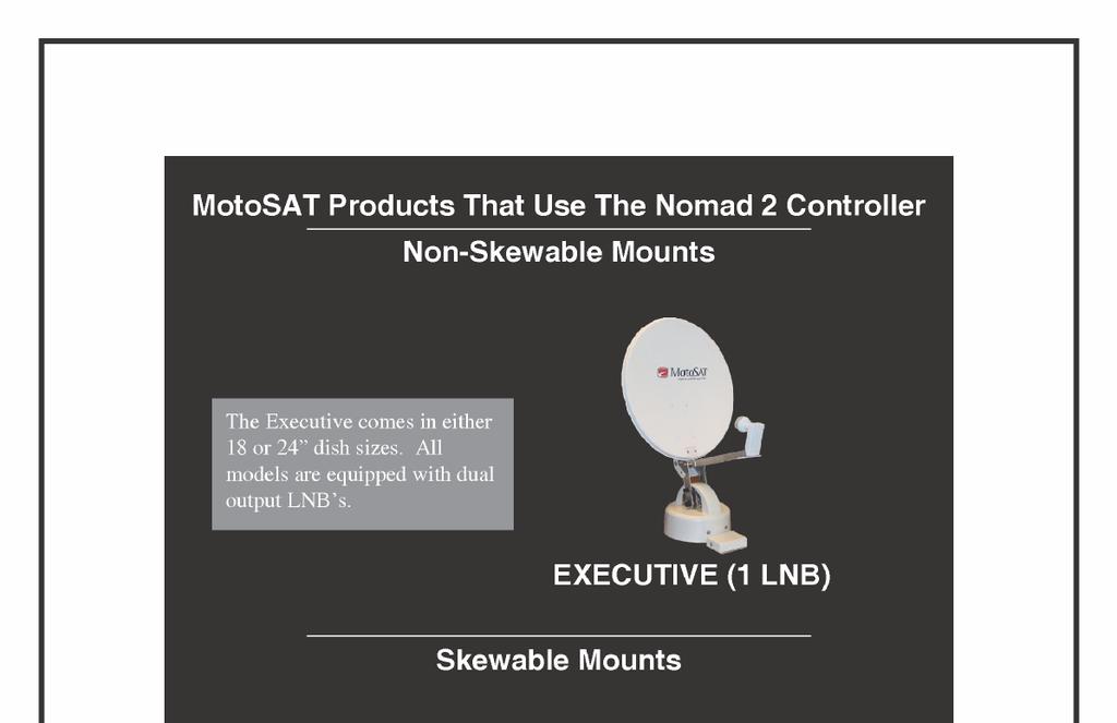
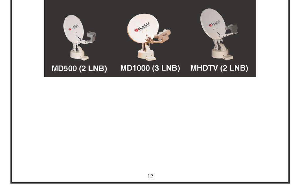
12 12
13 WIRING TABLE Open Face TV Mounts The Control Cable, 9 conductors, colored coded, 22Awg stranded that connects to the mount with a twist lock connector is configured in the following manner: Color Code Pin Designation Mount Destination Black 1 Motor, Azimuth Positive *Brown 2 Motor, Azimuth/Skew Negative *Red 3 Motor, Elevation/Skew Positive Orange 4 Motor, Elevation Negative Yellow 5 Sensor, Count Azimuth Green 6 Sensor, Ground Azimuth/Elevation Blue 7 Sensor Count Elevation White 8 Power, Mount LED **Purple 9 Sensor, Count Skew Counts per Degree * The Brown and Red wire perform a dual function when used on a Skewable (MD500/MD1000/MHDTV/Star Choice) mounts. These wires control the Skew motors when directed by the Nomad 2 Controller. Applying 12 volt power directly to these wires will skew the dish. **The Purple cable is for use on skewable dishes but it WILL NOT effect the operations of a nonskewable dish when it is connected (or not connected). The Mount is coil wrapped inside with the following cables and wire: 2 ea RG179 Teflon coated coax cables (can do four (4) if required) 1 ea Control Cable, 9 conductor cable, colored coded, 22Awg stranded. This cable is molded with a twist lock connector on one end and manually terminated at the Nomad 2 end with a 9 pin connector. 2 or 4 ea RG179 coax cables terminate at the LNB will provide additional cabling for multiple receivers. 1 ea Black and White 22Awg stranded wires carry the positive (white) voltage and ground (black) to the LED which is used to illuminate the dish face. For any questions or comments please contact our Technical Support Department at Ext
14 Programming Modes To get into the Program Mode.. 1. Turn the Nomad power OFF 2. Hold both the Find and Stow buttons down and hit the Power Button ON 3. Continue to hold Find and Stow button down for an additional 5 seconds after releasing the Power button 4. Release the Find and Stow buttons at this point and the front display lights will show the current satellite mode of the unit (Note: No Lights indicate Dish Network Non-Skewable mode. 5. Use the Find and Stow buttons to cycle through the light (LED) patterns until the desired configuration is shown. 6. Turn the Power off to store the programmed settings. 7. When you turn Power back on, you can do a Test Dish or Find satellite. 14
15 NOMAD 2 PROGRAMMING MODES By Service For software version V25 or higher MODEL NUMBER Skewable Orbital Position Multi Sat Nomad 2 LED(s) DIRECTV Executive 18"/24" NO 101 Only NO FIND Executive 18"/24" NO 101 or 119 NO PEAK / FIND MHDTV YES 101 / 110 / 119 YES FIND / STOW DISH NETWORK Executive 18"/24" NO 119 or 110 NO NO LIGHTS Executive 18"/24" NO 119 or 110 or 61.5 NO DVB / PEAK/ FIND Executive 18"/24" NO 119 or 110 or 129 NO LOCK / FIND Executive 18"/24" NO 119 or 110 or 148 NO LOCK MD500 YES 119 / 110 YES STOW MD YES 119 / 110 / 129 YES LOCK / STOW BELL EXPRESSVU Executive 18"/24" NO 82 or 91 NO PEAK MD500 YES 82 / 91 YES PEAK / STOW STAR CHOICE MSC60 YES / YES PEAK / FIND / STOW SHOW MODE (for display purposes) SKEWABLE YES Continuous Motion N/A DVB / FIND / STOW NON-SKEWABLE NO Continuous Motion N/A DVB / PEAK Note: The FREEDOM (fixed dome) will function with the Nomad 2. It is not recommended. It may be programmed as a NON-SKEWABLE system for any of the above NON-SKEWABLE configurations. At the push of the SATELLITE Button it will toggle sequentially though the satellites for which it is programmed. Nomad 2 Program LED s. 15
16 NOTE: The MD has 2 limitations that can affect its operation. 1. The MD has the same limitations that exist with the Dish Network D home coverage. Coverage is limited due to the footprint of the satellite signal on the 129 High Definition Satellite. You will be able to receive programming on the other two (2) satellites (110 and 119 ) when in the shaded areas but may have limited or no coverage of the 129 satellite. This limited coverage may extend past the shaded areas but is known to be a problem within the shaded areas. Please call Dish Network ( ) for any additional information. 2. The size of the dish makes wind loading a factor. While under most circumstances you will not be affected but when winds reach an excess of 25 MPH (depending upon the direction of the wind) you could experience the mount being moved off the satellite. If this should happen, simply press the FIND button and the system will re-peak for signal strength or re-find as required. 16
17 CLEARANCE DIAGRAMS 17
18 First Time Setup We have introduced an exciting new product, the Nomad 2. It has incorporated all the features that you (the dealer and consumer) have asked for. We are excited about it and know that you will be also. To help you become familiar with the programming, and to assist you in the first turn on, we are offering this Quick Guide to programming. After all connections are made please take the time to read through this guide once and then follow each step as outlined: TO PROGRAM Step 1: Make sure your Nomad 2 is turned OFF: Note: The Nomad 2 is OFF when the green light next to the power button is not lit. Step 2: Locate the FIND, STOW and POWER buttons on the Nomad 2: Read the following steps carefully before beginning With your right hand Press and hold down together the FIND and STOW buttons, while continuing to hold.. Use your left hand to Press the POWER button once and release Your right hand will continue holding down the FIND and STOW buttons for an additional 5-7 seconds. This will put the Nomad 2 into a Program Mode. Step 3: Refer to the diagram on page 15 in the Nomad 2 Manual to determine what Program Mode settings you will need for the type of MotoSAT system you have: Use the FIND or STOW button to navigate through the different settings on the front LED panel of the Nomad 2. When the light configuration on the Nomad 2 matches the selected diagram on the page 14, press the POWER button once to turn off the Nomad 2. This will store the configuration that you have set. Step 4: Turn on the Nomad 2 by pressing the POWER button. Wait 5-7 seconds for the Nomad 2 to perform startup sequences. TO TEST DISH Step 5: Complete a Test Dish by: Push both the FIND and STOW buttons at the same time. You will see the STOW light blink. It is indicating that the dish is moving. When the Test Dish is completed, the STOW light will stop blinking and go solid. TO LOCATE SATELLITE Step 6: Press the FIND button. This will locate your satellite(s) based upon the configuration settings that have been programmed. Thanks for buying a MotoSAT product. 18
19 TROUBLESHOOTING ERROR CODES ARE FLASHING LED LIGHTS AT 1 SECOND INTERVALS Stow Flashing: This is not an error but indicates the motors are moving. Find Flashing: Invalid Mode selected, Skewable vs. Non-Skewable. Find and Stow Flashing: Invalid Mode. Peak Flashing: Motor Time Out. No counts in Elevation. Peak and Stow Flashing: Motor Time Out. No counts in Azimuth. Peak and Find Flashing: Motor Time Out. No counts in Skew. Peak, Find and Stow Flashing: Limit Error in Elevation movement. DVB Flashing: Limit Error in Azimuth movement. DVB and Stow Flashing: Limit Error in Skew movement. DVB and Peak Flashing: Only Main satellite found. DVB, Peak and Stow Flashing: Main satellite not found but Secondary satellite was. DVB, Peak, Find and Stow Flashing: Signal lost, NO LNB Power Lock Flashing: No satellite found. Lock and Stow Flashing: Over Temperature on Satellite Receiver. Lock and Find Flashing: Dish did not raise high enough. Lock, Find and Stow Flashing: Coax cables on reversed on back of Nomad. Lock, Peak, Find and Stow Flashing: Could not find main satellite after Skew. Lock and DVB flashing: EEPROM failure. Lock, DVB and Stow flashing: AGC Control Failure. NOTE: Before calling Technical Support please perform a Test Dish and press Find one more time before you call. MotoSAT Customer/Technical Service ( Ext. 338) - Available Mon-Fri 8:00 a.m. to 5:00 p.m. Mountain Standard Time. Please have your MotoSAT Model # and Satellite Receiver Brand prior to calling Customer/Technical Support. 19
20 Special Notes Stowing the dish when all else fails. If you are able to go onto the roof - 1. Unplug the Green 9 pin connector from the back of the NOMAD 2. This will release dynamic braking that holds the mount in position. The mount may now be rotated manually. 2. Go to the roof where you can apply a slight amount of force to move the dish into an acceptable position for traveling.. In Azimuth, rotate the mount in a counter clock wise direction to move to the proper stowed position. 3. Plug the Green 9 pin connector back into the Nomad Call Tech Support when you can perform additional trouble shooting. If you are unable to go onto the roof The dish can be manipulated by applying 12 volt DC power to specific wires in the control cable located in the back of the NOMAD 2. The 12 Volts going to your NOMAD 2 controller (3 pin green connector) can be used as the 12 volt DC power source (see page 8.) 1. ELEVATION - Orange and Red wires (reversing polarity will change direction.) 2. AZIMUTH - Black and Brown (reversing polarity will change direction.) 3. SKEW - Brown and Red wires (reversing polarity will change direction.) If a chain or motor/gearbox assembly is broken, the dish will have to be stowed by hand. Dish Network receivers NON-SKEWABLE Open Faced mounts. If your satellite receiver is a Dish 500 or Dish Pro and you remove it from your home to your RV, you will need to perform a Check Switch while the non-skewable dish is in the STOWED POSITION. Your screen upon completion of the Check Switch should have 8 X s in the check boxes meaning that the Check Switch failed. This procedure must be accomplished before you FIND satellite. Failure to do so will result in improper operation of the receiver. 20
21 Nomad 1 & Nomad 2 Software Update 29 Jun 07 Required Equipment 1. Computer with 9 Pin Serial Port out (or adaptor). 2. Special 9-15 Pin Serial Cable (MotoSAT Part # CBL-SERIAL-DATA-10). A special configured cable that is available only through MotoSAT. Cost $19.00 PS&H. Overview Nomad & Nomad 2 Software Update This procedure outlines how to update the Nomad series controllers via your computer. A few key things to note are: *An automatic software upgrade module (MotoSAT Part # Module-Nomad (1) or (2)) is available through MotoSAT if a computer isn t available. This module attaches directly to the back of the Nomad series controller enabling it to load the new software. It can be ordered at No Charge. Customer will pay shipping (both ways). Module must be returned otherwise customer will be billed $65.00 against their Credit Card. Contact MotoSAT s Tech Support for more information.* For Any further questions, please contact MotoSAT s Tech Support team at: support@motosat.com Updating the Nomad 1 & Nomad 2 Controller Step 1-Opening HyperTerminal TURN OFF THE NOMAD CONTROLLER You now need to start a program on your computer to communicate with the Nomad. This Program is called HYPERTERMINAL. It can be found by clicking the START BUTTON, then 21


22 click ALL PROGRAMS, then click ACCESSORIES, then click COMMUNICATIONS, then click HYPERTERMINAL. Step 2- Configuring HyperTerminal Name your HyperTerminal Connection UPGRADE. You now need to choose your port you wish to use to connect to your Nomad. Generally COM 1 is the best choice. You must now enter properties for connecting using COM 1. 22

23 For the NOMAD 1, use the following: NOMAD 1 Bits per second: 9600 Data bits: 8 Parity: None Stop bits: 1 Flow control: Xon / Xoff For the NOMAD 2, use the following: NOMAD 2 Bits per second: Data bits: 8 Parity: None Stop bits: 1 Flow control: Xon / Xoff 23

![YOUR HYPERTERMINAL SETTINGS ARE NOW CONFIGURED Step 3- Loading software to the Nomad TURN ON YOUR CONTROLLER AND PRESS THE * KEY [SHIFT+8] ON THE](/docs-images/87/96788842/images/24-1.jpg "KEYBOARD, WITHIN 3 SECONDS AFTER POWERING THE CONTROLLER ON.")
24 After clicking OK, In the HyperTerminal window, click FILE, then PROPERTIES, then click the SETTINGS tab. Click the ASCII SETUP button. Change the LINE DELAY setting from 0, to 100. YOUR HYPERTERMINAL SETTINGS ARE NOW CONFIGURED Step 3- Loading software to the Nomad TURN ON YOUR CONTROLLER AND PRESS THE * KEY [SHIFT+8] ON THE KEYBOARD, WITHIN 3 SECONDS AFTER POWERING THE CONTROLLER ON. IF NOTHING APPEARS YOU HAVE CHOSEN THE WRONG COM PORT-REFER TO THE HYPERTERMINAL SETUP AND RECONFIGURE IF YOU SEE GAIN ADJUSTED YOU HAVE TAKEN TOO LONG TO PRESS THE * KEY. RETRY THE CONTROLLER POWER ON CYCLE AGAIN 24
25 If done correctly, the following screen will appear: At the local> prompt, type fbulk and press the ENTER key. YOU WILL RECEIVE THE local> PROMPT BACK At the local> prompt, type fload and press the ENTER key. YOU WILL NOT RECEIVE THE local> PROMPT THIS TIME You can now send software to the Nomad for updating. On the HyperTerminal window click TRANSFER, then click SEND TEXT FILE. Browse for the Nomad file you wish to send to the Nomad controller. Usually it can be found on your DESKTOP, or in MY DOCUMENTS. 25

26 The file will then load indicated by stars across the screen as shown below: When the software has been loaded, you will again receive the local> prompt. Type default at this prompt, then press the ENTER button. YOUR NOMAD 1 or 2 HAS NOW BEEN UPGRADED! YOU MUST NOW RUN A TEST DISH IN ORDER TO ENSURE PROPER FUNCTIONALITY. Nomad 1 Test Dish Procedure You will need to run a TESTDISH. Do this by turning off the nomad, placing Switch 1 in the on or up position, turning on the nomad, and waiting for the test dish to finish. Turn off the nomad, change Switch 1 back to the off or down position and turn the nomad back on. BE SURE TO HAVE THE 3 RD SWITCH UP IF THE DISH YOU ARE USING HAS A SKEWABLE FACE! Nomad 2 Test Dish Procedure Simply press the SEARCH AND STOW BUTTONS AT THE SAME TIME. This will run a test dish on your system South Milestone Dr. Salt Lake City, UT
OSD. EXECUTIVE / MiniDome USERS MANUAL. USING THE MOTOSAT DISH POINTING SYSTEM EXECUTIVE / MiniDome OSD
 EXECUTIVE / MiniDome OSD USERS MANUAL USING THE MOTOSAT DISH POINTING SYSTEM EXECUTIVE / MiniDome OSD MotoSAT Corporation Created April 22, 2003 1-800-247-7486 CONGRATULATIONS! on your purchase of your
EAGLE RE-1 CONTROLLER For Use On MotoSAT HD Mounts
 EAGLE RE-1 CONTROLLER For Use On MotoSAT HD Mounts Supported Systems HD SL5 DirecTV HD DP3 Dish Network HD SC2 SHAW HD DP3 BELL TV EXECUTIVE DirecTV 101 Dish Network 119 MSC-60 SHAW MD-500 Dish Network
EAGLE RE-1 CONTROLLER
 EAGLE RE-1 CONTROLLER For Use On ALL MotoSAT Mounts Supported Systems HD SL5 DirecTV HD DP3 Dish Network HD SC2 SHAW HD DP3 BELL TV EXECUTIVE 18" DirecTV 101 Dish Network 119 MSC-60 SHAW MD-500 Dish Network
SATELLITE TV OPERATION / TECHNICAL MANUAL. Eagle II Controller
 SATELLITE TV OPERATION / TECHNICAL MANUAL Eagle II Controller 10 May 2018 2 Index Warnings... 4 Mount Definitions... 5 Controller Views... 6 Configuration and Software Versions... 8 Menus and Operations...
SATELLITE TV OPERATION / TECHNICAL MANUAL. Eagle II Controller
 SATELLITE TV OPERATION / TECHNICAL MANUAL Eagle II Controller 8 Nov 2017 2 Index Warnings... 4 Mount Definitions... 5 Controller Views... 6 Configuration and Software Versions... 8 Menus and Operations...
Installing a MotoSat MD500 for Dish Network on a RB Born Free
 Installing a MotoSat MD500 for Dish Network on a 2005 24RB Born Free 1 2005 24RB July 2006 I have Dish network using satellites 110 and 119 and had decided on using the MotoSat MD500 rather than the dome
Satellite TV. Nomad SD2 USER GUIDE. Software Version 100 or higher. ALL RIGHTS RESERVED Rev 4 Mar, Nomad SD2 Manual
 Satellite TV Nomad SD2 USER GUIDE Software Version 100 or higher ALL RIGHTS RESERVED Rev 4 Mar, 10 901-Nomad SD2 Manual INDEX DEFINITIONS 3 FEATURES 4 Front Panel description 5 Rear Panel description 6
DataSAT ACU-2 Controller Wiring Configuration - Operation
 DataSAT ACU-2 Controller Wiring Configuration - Operation This manual covers basic wiring, antenna controller configurations, and typical operation. For proper operation, wiring and configuration are very
USER MANUEL. SNIPE 2 Ref R13
 USER MANUEL SNIPE 2 Ref. 0141317R13 Contents 1. General Information 1-1. Introduction 1-2. Proper use and operation 1-3. Safety notes......... 2 3 3 2. Contents 2-1. Accessory included 2-2. Name of parts......
Troubleshooting Guide 9630 Series
 Troubleshooting Guide 9630 Series Satellite Solutions for Mobile Markets 11200 Hampshire Avenue South, Bloomington, MN 55438-2453 Phone: (800) 982-9920 Fax: (952) 922-8424 www.kingcontrols.com 1305-SEMI
Fully ly Automaticti. Motorised Satellite t TV System. User s manual. ver 3.0.
 ver 3.0 Fully ly Automaticti Motorised Satellite t TV System User s manual Customer Help Line: 1300 139 255 Support Email: support@satkingpromax.com.au Website: www.satkingpromax.com.au www.satkingpromax.com.au
Field Service Procedure Replacement GACP Control Panel Kit, ST24
 1. Brief Summary: Troubleshooting document for diagnosing a fault with and replacing the Graphic Antenna Control Panel (GACP) for the ST24 antenna. 2. Checklist: Verify Power to the GACP Verify Communications
RV SATELLITE ANTENNA AUTOMATIC SKEW TWIN LNB SSA-850
 RV SATELLITE ANTENNA AUTOMATIC SKEW TWIN LNB SSA-850 INSTALLATION AND OPERATION MANUAL Please ensure that this manual is read in full prior to installing or using this sphere satellite unit. Design and
MESA FIXED AUTOMATIC. Andrews/Raven Installer Manual // MESA. Rev 23 June MESA A/R Installation
 MESA FIXED AUTOMATIC // MESA Andrews/Raven Installer Manual 901-MESA A/R Installation Rev 23 June 10 A/R Installer Manual WHAT IS A MESA The MESA is a three (3) axis (Azimuth, Elevation and Skew) Automatic
Portable Automatic Satellite System. Model VQ2000
 Portable Automatic Satellite System with built-in DVB for positive satellite identification Model VQ2000 Operating Instructions Satellite Solutions for Mobile Markets 11200 Hampshire Avenue South, Bloomington,
RF Mogul. Operation Manual. MotoSAT J1/D4 Controllers. Firmware Upgrade for
 RF Mogul Firmware Upgrade for MotoSAT J1/D4 Controllers Operation Manual Version 14.01 13 April 2014 Index SDC1 Satellite Dish Controller Features 1 Getting Started 2 Quick Setup 2 Front Panel Operation
Fully ly Automaticti. Motorised Satellite t TV System. User s manual REV
 REV. 1.0 Fully ly Automaticti Motorised Satellite t TV System User s manual Customer Help Line: 1300 139 255 Support Email: support@satkingpromax.com.au Website: www.satkingpromax.com.au www.satkingpromax.com.au
Portable In-Motion Automatic Satellite System. Model VQ3000
 Portable In-Motion Automatic Satellite System with built-in DVB for positive satellite identification Model VQ3000 Operating Instructions Satellite Solutions for Mobile Markets 11200 Hampshire Avenue South,
Specifications. Compatible Receivers. Compatible Satellites. DIRECTV Sat DISH Sat DIRECTV Receiver Compatibility
 Quick Setup Make sure the Carryout G2 antenna is in a location with a clear view of the southern sky. Connect the provided coaxial cable from the primary receiver to the MAIN port on the base. Connect
GEOSATpro GS120. DiSEqC 1.2 Motorized H-H H Motor
 DiSEqC 1.2 Motorized H-H H Motor GEOSATpro GS120 Compatible with DiSEqC 1.2 & USALS Receivers Adjustable Hardware Limiters for 140 Degree Coverage Goto X Preprogrammed for North American Satellites LED
MESA FIXED AUTOMATIC. PRODELIN Installer Manual // MESA. Rev 23 June MESA Prodelin Installation
 MESA FIXED AUTOMATIC // MESA PRODELIN Installer Manual 901-MESA Prodelin Installation Rev 23 June 10 WHAT IS A MESA The MESA is a three (3) axis (Azimuth, Elevation and Skew) Automatic Fixed Mounting system.
TracVision Interface Box Circular Configuration for North America. TracVision Interface Box User s Guide
 TracVision Interface Box Circular Configuration for North America TracVision Interface Box User s Guide TracVision Interface Box Circular Configuration for North America User s Guide This user s guide
Field Service Procedure Replacement PCU Kit, ST24
 1. Brief Summary: Troubleshooting document for diagnosing a fault with and replacing the main PCU PCB on the ST24 antenna. 2. Checklist: Verify Initialization Built In Test 3. Theory of Operation: The
Contents. 1. General Information. 2. Contents. 3. Operating Instruction. 4. Program update. 5. Trouble Shooting. 6. Specifications
 Contents 1. General Information 1-1. Introduction 1-2. Proper use and operation 1-3. Safety Notes 2. Contents 2-1. Accessory Include 2-2. Name of parts 3. Operating Instruction 3-1. Connection Diagram
Receiver Description and Installation
 Receiver Front Panel Smart Card Door Behind this door is a slot for a future smart card. No smart card is included with this receiver. Arrow Buttons Use the ARROW buttons to change channels on the nearby
Dealer Training Test. Winegard Dealer Training
 Dealer Training Test Winegard Dealer Training Test 105 General Information 1. Most RV wiring uses two types of coax cable, RG-59 and RG-6. Which type of coax cable should be used for satellite applications?
In-Motion Automatic Satellite System. Model V30
 In-Motion Automatic Satellite System with built-in DVB for positive satellite identification Model V30 Installation and Operating Instructions Satellite Solutions for Mobile Markets 11200 Hampshire Avenue
In-Motion Automatic Satellite System. Model V30
 In-Motion Automatic Satellite System with built-in DVB for positive satellite identification Model V30 Installation and Operating Instructions Satellite Solutions for Mobile Markets 11200 Hampshire Avenue
RF Mogul. Quick Start. Model: SDC1. Satellite Dish Controller
 RF Mogul Satellite Dish Controller Model: SDC1 Quick Start 29 February 2012 Minimum required hardware to find a Satellite! This Quick Start document is for connecting and operating a General Dynamics C125M
TracVision R6DX Installation Guide
 TracVision R6DX Installation Guide TracVision R6DX Installation Guide KVH s Premier Satellite TV System for RVs These instructions explain how to install the TracVision R6DX on an RV or motor coach. Complete
TracVision R6DX Installation Guide
 TracVision R6DX Installation Guide These instructions explain how to install the TracVision R6DX satellite TV antenna system on an RV or motor coach. Complete instructions on how to use the system are
Master Clock Controller. User Guide. pyramidtimesystems.com
 Master Clock Controller User Guide pyramidtimesystems.com TABLE OF CONTENTS TABLE OF CONTENTS... PRODUCT OVERVIEW... FEATURES... 3 CONTENTS... 4 WALL MOUNTING... 5 INSTALLATION... 6 PROGRAMMING... 7-8
DSIM-GI Installation Guide Revision P
 Installation Guide Revision P 1. Quick Start Instructions for Single Pilot AGC Operatation 1. With the ADU jumper in Auto position, turn ADU pot to MIN amplifier output level. Then place the ADU jumper
15 Marine Satellite System. Model 1200-KU
 15 Marine Satellite System with built-in DVB for positive satellite identification Model 1200-KU Installation and Operating Instructions Satellite Solutions for Mobile Markets 11200 Hampshire Avenue South,
Troubleshooting Guide
 Troubleshooting Guide 9760 Series 9762 Series Satellite Solutions for Mobile Markets 11200 Hampshire Avenue South, Bloomington, MN 55438-2453 Phone: (800) 982-9920 Fax: (952) 922-8424 www.kingcontrols.com
WINEGARD INSTALLATION MANUAL. Model GM Carryout Ladder Mount for mounting pipes with outer diameters between 1 to 1-1/8
 WINEGARD INSTALLATION MANUAL Model GM-3000 Carryout Ladder Mount for mounting pipes with outer diameters between 1 to 1-1/8 WARNING: DO NOT USE THE LADDER MOUNT AS A STEP! NOT INTENDED FOR USE WITH THE
User Guide. Do not return antenna to place of purchase
 User Guide For help, email help@winegard.com or call 1-800-788-4417 For Receivers and Programming, call 1-866-609-9374 For up-to-date information on receiver compatibility and programming, visit www.winegard.com/receivers
Kramer Electronics, Ltd. USER MANUAL. Models: VS-162AV, 16x16 Audio-Video Matrix Switcher VS-162AVRCA, 16x16 Audio-Video Matrix Switcher
 Kramer Electronics, Ltd. USER MANUAL Models: VS-162AV, 16x16 Audio-Video Matrix Switcher VS-162AVRCA, 16x16 Audio-Video Matrix Switcher Contents Contents 1 Introduction 1 2 Getting Started 1 3 Overview
For receivers and programming, call
 Instruction Manual for DISH Users www.winegard.com/mobile For receivers and programming, call 1-866-609-9374 For up-to-date information on receiver compatibility and programming, visit www.winegard.com/receivers
Installation Manual. Automatic Multi-Satellite TV Antenna. Model SK-1000 TRAV LER DISH /Bell TV Antenna
 Installation Manual Automatic Multi-Satellite TV Antenna Model SK-1000 TRAV LER DISH /Bell TV Antenna www.winegard.com/mobile For Technical Services, email help@winegard.com or call 1-800-788-4417 For
TracVision R6 & Multi-service Interface Box. User s Guide
 TracVision R6 & Multi-service Interface Box User s Guide Welcome to TracVision R6 TracVision User s Guide R6 Satellite TV Antenna & Interface Box This manual provides detailed instructions on the proper
Instruction Manual for DIRECTV Users
 Instruction Manual for DIRECTV Users www.winegard.com/mobile For receivers and programming, call 1-866-609-9374 For up-to-date information on receiver compatibility and programming, visit www.winegard.com/receivers
Installation / Set-up of Autoread Camera System to DS1000/DS1200 Inserters
 Installation / Set-up of Autoread Camera System to DS1000/DS1200 Inserters Written By: Colin Langridge Issue: Draft Date: 03 rd July 2008 1 Date: 29 th July 2008 2 Date: 20 th August 2008 3 Date: 02 nd
Fully Automatic Satellite TV System
 Fully Automatic Satellite TV System Are you looking for a fully automatic satellite TV system that is easy to install and very easy to use? The SatKing Pro Max is the most advanced Motorised Satellite
TracVision 95W LNB Installation
 TracVision 95W LNB Installation To enable a TracVision system to receive DIRECTV international programming from the linear satellite located at 95W, a 95W LNB must be installed in a secondary M7SK or M9
UC1000 Universal Controller
 UC1000 Universal Controller Makes the KING Quest Satellite Antenna System compatible with DIRECTV DISH Bell TV Please read the! BEFORE YOU START! section on the inside of this cover before using the UC1000
INSTALLATION AND OPERATION INSTRUCTIONS EVOLUTION VIDEO DISTRIBUTION SYSTEM
 INSTALLATION AND OPERATION INSTRUCTIONS EVOLUTION VIDEO DISTRIBUTION SYSTEM ATTENTION: READ THE ENTIRE INSTRUCTION SHEET BEFORE STARTING THE INSTALLATION PROCESS. WARNING! Do not begin to install your
Master Clock Controller. User Guide. pyramidtimesystems.com
 Master Clock Controller User Guide pyramidtimesystems.com TABLE OF CONTENTS TABLE OF CONTENTS... PRODUCT OVERVIEW... FEATURES... 3 CONTENTS... 4 WALL MOUNTING... 5 INSTALLATION... 6 PROGRAMMING... 7-8
Master Clock Controller. User Guide. pyramidtimesystems.com
 Master Clock Controller User Guide pyramidtimesystems.com TABLE OF CONTENTS TABLE OF CONTENTS... PRODUCT OVERVIEW... FEATURES... 3 CONTENTS... 4 WALL MOUNTING... 5 INSTALLATION... 6 PROGRAMMING... 7-8
Satellite Dish Installation Manual (Ver. 2) 1
 1") Satellite Dish Installation Manual Provided by DiscoverNet, Inc. Satellite Dish Installation Manual (Ver. 2) 1 Table of Contents Section 1: Introduction Page 3 Section 2: Recommended Tools and Materials
Satellite Dish Installation Manual Provided by DiscoverNet, Inc. Satellite Dish Installation Manual (Ver. 2) 1 Table of Contents Section 1: Introduction Page 3 Section 2: Recommended Tools and Materials
Chapter 4. Dish Antenna Installation. Installing a DISH 500 Antenna. Finding the Satellites
 These instructions guide you through the installation of a satellite system which includes your receiver (included with this manual), and a DISH Pro DISH 500 antenna system that can be identified by the
Field Service Procedure Replacement PCU Kit, Coastal
 1. Brief Summary: Troubleshooting document for diagnosing a fault with and replacing the PCU assembly on the coastal series antennas. 2. Checklist: Initialization Rate Sensor Outputs Run the Built In Test
Installation Manual. Automatic Multi-Satellite TV Antenna. Model SK-7003 TRAV LER Shaw Direct Antenna
 Installation Manual Automatic Multi-Satellite TV Antenna Model SK-7003 TRAV LER Shaw Direct Antenna www.winegard.com/mobile For Technical Services, email help@winegard.com or call 1-800-788-4417 Product
Specifications. Dual Satellite Tracking Meter. With a built in 22Khz tone generator. Overview
 Dual Satellite Tracking Meter 38.8 With a built in Khz tone generator Specifications Power demand over 800 ma will result in an Over Current indication. Compatible With STARBAND Receivers Input Frequency:
Guide for Using DIRECTV SWM Technology with Winegard Mobile Satellite TV Antennas
 Guide for Using DIRECTV SWM Technology with Winegard Mobile Satellite TV Antennas For up-to-date information on receiver compatibility & programming, visit www.winegard.com/receivers 2452242 Receivers
Installation Manual. Automatic Multi-Satellite TV Antenna. Model SK-7003 TRAV LER Shaw Direct Antenna
 Installation Manual Automatic Multi-Satellite TV Antenna Model SK-7003 TRAV LER Shaw Direct Antenna www.winegard.com/mobile For Technical Services, email help@winegard.com or call 1-800-788-4417 Product
TracVision M3 DX Version. Circular Configuration. TracVision M3 User s Guide
 TracVision M3 DX Version Circular Configuration TracVision M3 User s Guide TracVision M3DX Circular Configuration User s Guide This user s guide provides all of the basic information you need to operate,
Non-Hopper Receiver Installation
 TABLE OF CONTENTS Wally on page ViP General Setup on page ViP 922 on page WALLY The Wally will install the same way the current ViP 211 receivers do The Wally does not support more than one TV and does
Troubleshooting. 1. Symptom: Status indicator (Red LED) on SSR is constant on. 2. Symptom: Output indicator (Yellow LED) on SSR is flashing.
 on SSR is constant on. 2. Symptom: Output indicator (Yellow LED) on SSR is flashing.") Product Data Electrical Data SST (Transmitter) SSR (Receiver) Supply voltage 18 30 V dc Max. Voltage ripple 15 % (within supply range) Current consumption 100 ma (RMS) 75 ma Digital - 100 ma Max. outputs
Product Data Electrical Data SST (Transmitter) SSR (Receiver) Supply voltage 18 30 V dc Max. Voltage ripple 15 % (within supply range) Current consumption 100 ma (RMS) 75 ma Digital - 100 ma Max. outputs
Instruction Manual. Do not return antenna to place of purchase. Power Inserter. See page 2 for setup instructions
 Instruction Manual SD SD/HD SD/HD Do not return antenna to place of purchase Power Inserter See page 2 for setup instructions 2452360 Specifications Compatible with DIRECTV, DISH, & Bell TV programming
SNG-2150C User s Guide
 SNG-2150C User s Guide Avcom of Virginia SNG-2150C User s Guide 7730 Whitepine Road Revision 001 Richmond, VA 23237 USA GENERAL SAFETY If one or more components of your earth station are connected to 120
RSSL1:1-KuXER. Outdoor Unit (ODU) Ku Ext Ref LNB Redundancy System with external 10 MHz Reference System. Mux/Tee. Coax cable
 Ku Ext Ref LNB Redundancy System with external 10 MHz Reference System. Mux/Tee. Coax cable") RSSL1:1-KuXER Ku Ext Ref LNB Redundancy System with external 10 MHz Reference System Outdoor Unit (ODU) Waveguide Switch & Status LNB 1 Coax cable Interface Terminal LNB 2 Indoor Unit Outdoor Unit Indoor
RSSL1:1-KuXER Ku Ext Ref LNB Redundancy System with external 10 MHz Reference System Outdoor Unit (ODU) Waveguide Switch & Status LNB 1 Coax cable Interface Terminal LNB 2 Indoor Unit Outdoor Unit Indoor
APOLLO DESIGN TECHNOLOGY 4130 Fourier Drive Fort Wayne, IN USA Phone: Fax:
 APOLLO DESIGN TECHNOLOGY 4130 Fourier Drive Fort Wayne, IN 46818 USA Phone: +01.260.497.9191 Fax: +01.260.497.9192 www.apollodesign.net 07.26.10 Operating Manual [ Table of Contents ] Safety Information.
ATLANTA ASF 2033HD+ DVB-S/S2 METER. User`s Manual
 ATLANTA ASF 2033HD+ DVB-S/S2 METER User`s Manual Buttons and Indicators... 2 How to measure... 3 Main menu... 4 LNB Setting... 4 Edit Satellite... 6 Spectrum Chart... 7 Constellation... 9 Angle Calculation...
DSIM-AF Installation Guide Revision B
 Installation Guide Revision B 1. Quick Start Instructions for Single Pilot AGC Operatation 1. Remove the RF module cover and install the DSIM-AF AGC module into the amplifier. 2. Turn the ALC switch to
POINTS POSITION INDICATOR PPI4
 POINTS POSITION INDICATOR PPI4 Monitors the brief positive operating voltage across points motors when they are switched Lights a corresponding led on a control panel to show the last operation of each
Satellite Television. A Guide to TracVision LF/SF. owner s manual. Installation Instructions User s Guide Technical Manual. KVH TracVision LF/SF
 A Guide to TracVision LF/SF owner s manual Installation Instructions User s Guide Technical Manual KVH TracVision LF/SF Satellite Television TracVision LF/SF Owner s Manual Addendum (ECO # 6857) The following
Automatic Satellite System. Model V20
 Automatic Satellite System with built-in DVB for positive satellite identification Model V20 Installation and Operating Instructions Satellite Solutions for Mobile Markets 11200 Hampshire Avenue South,
Vorne Industries. 87/719 Analog Input Module User's Manual Industrial Drive Itasca, IL (630) Telefax (630)
 Telefax (630)") Vorne Industries 87/719 Analog Input Module User's Manual 1445 Industrial Drive Itasca, IL 60143-1849 (630) 875-3600 Telefax (630) 875-3609 . 3 Chapter 1 Introduction... 1.1 Accessing Wiring Connections
Vorne Industries 87/719 Analog Input Module User's Manual 1445 Industrial Drive Itasca, IL 60143-1849 (630) 875-3600 Telefax (630) 875-3609 . 3 Chapter 1 Introduction... 1.1 Accessing Wiring Connections
WINEGARD. Operation Manual Made in the U.S.A. For up-to-date information on receiver compatibility and programming, visit
 WINEGARD Carryout Automatic Portable Satellite TV Antenna Operation Manual Made in the U.S.A. For up-to-date information on receiver compatibility and programming, visit www.winegard.com/receivers For
DLM471S-5.1 MULTICHANNEL AUDIO LEVEL MASTER OPERATION MANUAL IB B. (Mounted in RMS400 Rack Mount & Power Supply) (One of 4 Typical Cards)
 (One of 4 Typical Cards)") DLM471S-5.1 (Mounted in RMS400 Rack Mount & Power Supply) MULTICHANNEL AUDIO LEVEL MASTER (One of 4 Typical Cards) OPERATION MANUAL IB6432-02B TABLE OF CONTENTS PAGE 1.0 GENERAL DESCRIPTION 2 2.0 INSTALLATION
DLM471S-5.1 (Mounted in RMS400 Rack Mount & Power Supply) MULTICHANNEL AUDIO LEVEL MASTER (One of 4 Typical Cards) OPERATION MANUAL IB6432-02B TABLE OF CONTENTS PAGE 1.0 GENERAL DESCRIPTION 2 2.0 INSTALLATION
MODEL... MXL012/55NZ MXL012/65NZ SIMPLICITY AT IT S BEST SET UP & USER MANUAL REGISTERED COMMUNITY DESIGN NO
 SIMPLICITY AT IT S BEST MODEL... MXL012/55NZ MXL012/65NZ SET UP & USER MANUAL REGISTERED COMMUNITY DESIGN NO.2207746. PATENT PENDING SIMPLICITY AT IT S BEST THANK YOU! For purchasing this product, we trust
USER MANUAL FOR THE ANALOGIC GAUGE FIRMWARE VERSION 1.1
 by USER MANUAL FOR THE ANALOGIC GAUGE FIRMWARE VERSION 1.1 www.aeroforcetech.com Made in the USA! WARNING Vehicle operator should focus primary attention to the road while using the Interceptor. The information
RAINIERCISCOCOMMERCIALD9865 D - H - B RECEIVERQUICKTIPS.
 RAINIERCISCOCOMMERCIALD9865 D - H - B RECEIVERQUICKTIPS. PLEASE READ DOCUMENT FULLY BEFORE ATTEMPTING TO PROGRAM DATA. Pre-setup Procedure Connect with RG6u 1450 mhz or better jumper cable using compression
TracVision. with Multi-service Interface Box/Controller. TracVision M1DX User s Guide
 TracVision M1DX with Multi-service Interface Box/Controller TracVision M1DX User s Guide TracVision M1DX Multi-service Interface Box/ Controller Configuration User s Guide This user s guide provides all
In-Motion Satellite System. Model 9754 Model 9754-LP
 In-Motion Satellite System with built-in DVB for positive satellite identification Model 9754 Model 9754-LP Installation and Operating Instructions Satellite Solutions for Mobile Markets 11200 Hampshire
Satellite Television. A Guide to TracVision 6. user s guide. Operating Instructions. KVH TracVision 6
 A Guide to TracVision 6 user s guide Operating Instructions Satellite Television KVH TracVision 6 Welcome to TracVision 6 TracVision 6 User s Guide Congratulations on your choice of the TracVision 6, one
By CHANNEL VISION. Flush Mount Amplifier A0350
 Spkrs Local In IR In 24VDC A0350 10 The A0350 can be used with Channel Vision s CAT5 audio hubs to provide a powerful 50Watts per channel in the listening zone. Alternatively, the A0350 can be added to
General Wiring and Installation Guidelines. Typical Mounting Installations Electrical Connections General Guidelines Common Questions & Answers
 General Wiring and Installation Guidelines Typical Mounting Installations Electrical Connections General Guidelines Common Questions & Answers Congratulations on your purchase of a Dynapar brand encoder.
WINEGARD. TRAV LER Automatic Multi-Satellite TV Antenna. Model SK-3003 DIRECTV TRIPLE FEED INSTALLATION MANUAL. Made in the U.S.A.
 WINEGARD TRAV LER Automatic Multi-Satellite TV Antenna Model SK-3003 DIRECTV TRIPLE FEED MANUAL Made in the U.S.A. SK-3003 Winegard Company 3000 Kirkwood St. Burlington, IA 52601-2000 319/754-0600 FAX
Revision Protocol Date Author Company Description January Paul DOS REMEDIO S. Imagine Communications
 PRODUCT ADC TOPIC ODETICS TCS-90 CART MACHINE DATE: January 25, 2001 REVISION HISTORY Revision Protocol Date Author Company Description 1.1 25 January 2001 Paul DOS REMEDIO S Imagine Communications New
Revision Protocol Date Author Company Description 1.1 May 14, Seth LOUTH Revised for formatting
 PRODUCT ADC TOPIC ODETICS TCS-2000 CART MACHINE DATE: May 14, 1999 REVISION HISTORY Revision Protocol Date Author Company Description 1.1 May 14, Seth LOUTH Revised for formatting 1999 Olitzky 1.0 Aug.
Be sure to run the vehicle engine while using this unit to avoid battery exhaustion.
 CAUTION: TO REDUCE THE RISK OF ELECTRIC SHOCK DO NOT REMOVE COVER (OR BACK) NO USER-SERVICEABLE PARTS INSIDE REFER SERVICING TO QUALIFIED SERVICE PERSONNE; Please Read all of these instructions regarding
Cellular Signal Booster
 Connect 4G-X Cellular Signal Booster !! IT IS VERY MPORTANT TO POWER YOUR SIGNAL BOOSTER US NG A SURGE PROTECTED AC POWER STRIP WITH AT LEAST A 1000 JOULE RATING. FAILURE TO DO THIS WILL VOID YOUR WARRANTY
Safety Information. Camera System. If you back up while looking only at the monitor, you may cause damage or injury. Always back up slowly.
 Table of Contents Introduction...3 Safety Information...4-6 Before Beginning Installation...7 Installation Guide...8 Wiring Camera & Monitor...9-10 Replacement Installation Diagram...11 Clip-On Installation
PORTABLE SATELLITE TV SYSTEM VQ1000 OPERATION MANUAL
 PORTABLE SATELLITE TV SYSTEM VQ1000 OPERATION MANUAL Notes: Introduction Congratulations on your purchase of the ultra-portable VuQube Satellite TV Antenna. The VuQube is equipped with a wireless remote
Satellite Television. A Guide to TracVision LF/SF. owner s manual. Installation Instructions User s Guide Technical Manual. KVH TracVision LF/SF
 A Guide to TracVision LF/SF owner s manual Installation Instructions User s Guide Technical Manual KVH TracVision LF/SF Satellite Television TracVision LF/SF Owner s Manual Addendum (ECO #s 6768, 6797)
Extra long-range RFID (proximity) card reader
 card reader") GP90A Extra long-range RFID (proximity) card reader (1) Features: Extra long reading range of up to 90 cm with ISO-size passive RFID cards*, over 100 cm with special optimized passive cards High-precision
GP90A Extra long-range RFID (proximity) card reader (1) Features: Extra long reading range of up to 90 cm with ISO-size passive RFID cards*, over 100 cm with special optimized passive cards High-precision
WINEGARD. RoadTrip Digital Satellite Mobile TV Antenna for Two Receivers. OPERATION MANUAL Made in the U.S.A. U.S. Patent Nos.
 WINEGARD RoadTrip Digital Satellite Mobile TV Antenna for Two Receivers RoadTrip SD - Stationary Satellite TV Antenna RoadTrip SDi - In-Motion Satellite TV Antenna OPERATION MANUAL Made in the U.S.A. U.S.
JAMAR TRAX RD Detector Package Power Requirements Installation Setting Up The Unit
 JAMAR TRAX RD The TRAX RD is an automatic traffic recorder designed and built by JAMAR Technologies, Inc. Since the unit is a Raw Data unit, it records a time stamp of every sensor hit that occurs during
VHF + UHF Amplified HDTV Antenna Model OA8000 & OA8001 Installation Instructions Reception Frequencies
 VHF + UHF Amplified HDTV Antenna Model OA8000 & OA8001 Installation Instructions Reception Frequencies VHF: 54-216 MHz UHF: 470-698 MHz FM: 87.9-107.9 MHz Voltage Input: AC110-120V / AC220-240V Working:
VBOX III 100Hz GPS Speed Sensor. User Guide. Page 1 of 21. VBOX III SPS User Guide
 VBOX III 100Hz GPS Speed Sensor User Guide Page 1 of 21 VBOX III OVERVIEW... 3 INTRODUCTION... 4 FEATURES... 4 STANDARD INVENTORY... 5 OPTIONAL ACCESSORIES... 5 OPERATION... 6 GETTING STARTED... 12 VBOX.EXE
FRONT PANEL FUNCTIONAL SPECIFICATIONS
 FRONT PANEL FUNCTIONAL SPECIFICATIONS 1- On-Off Switch : for use to turn on and turn off of the device 2- Sat Select Button : for use transition to the satellite receivers 3- Sat Select Indicator : Shows
MS2540 Current Loop Receiver with RS485 Communication
 MS2540 Current Loop Receiver with RS485 Communication User Manual Metal Samples Company A Division of Alabama Specialty Products, Inc. 152 Metal Samples Rd., Munford, AL 36268 Phone: (256) 358 4202 Fax:
Bonding. Black Ground Wire Indicates # 17ga CCS Bond. Green Bonding Wire Indicates # 10ga Solid Copper. External Wall
 SWiM Integrated LNB Installation KaKu - HD DVR SWiM compatible Single tuner SWiM compatible 4 way single port DC power passing splitter rated from 2-2150MHz BBC s are not required in this scenario Weather
Syntor X Flash Memory Module Revision C
 Syntor X Flash Memory Module Revision C The PIEXX SynXFlash memory module, along with the supplied PC software, replaces the original SyntorX code plugs and allows you to easily set modify and update your
TracVision M5/M7 User s Guide
 TracVision M5/M7 GyroTrac Configuration TracVision M5/M7 User s Guide TracVision M7 with Auto Skew Important Information About Your System Important Information About Your TracVision M7 System with Auto
SOURCE COMMANDER MSS433 A/V SELECTOR OWNER S MANUAL INSTALLATION GUIDE
 SOURCE COMMANDER MSS433 R L V R L V R L V R L V M U L T I S T A T I O N A/V SELECTOR OWNER S MANUAL INSTALLATION GUIDE OWNER S MANUAL/INSTALLATION GUIDE WARNING! THE CLARION MSS433 MULTISTATION A/V SELECTOR
Operating Manual for Clock / Auxiliary Displays for VHX systems
 Operating Manual for Clock / Auxiliary Displays for VHX systems The VHX auxiliary display module is designed to work with a Dakota Digital VHX system and will not function properly on its own. With this
Connecting To and Programming the LPC2148 Blue Board. Method 1 ISP (In-System Programming) w/ Flash Magic
 w/ Flash Magic") Connecting To and Programming the LPC2148 Blue Board We have two primary methods of programming the LPC2148 Blue Board. We can use the supplied bootloader with ISP (In-System Programming) or JTAG (better
Connecting To and Programming the LPC2148 Blue Board We have two primary methods of programming the LPC2148 Blue Board. We can use the supplied bootloader with ISP (In-System Programming) or JTAG (better