Introduction. Accessories. Pan/Tilt Control Panel AW-RP400 NOTE
|
|
|
- Annabella Benson
- 5 years ago
- Views:
Transcription
1
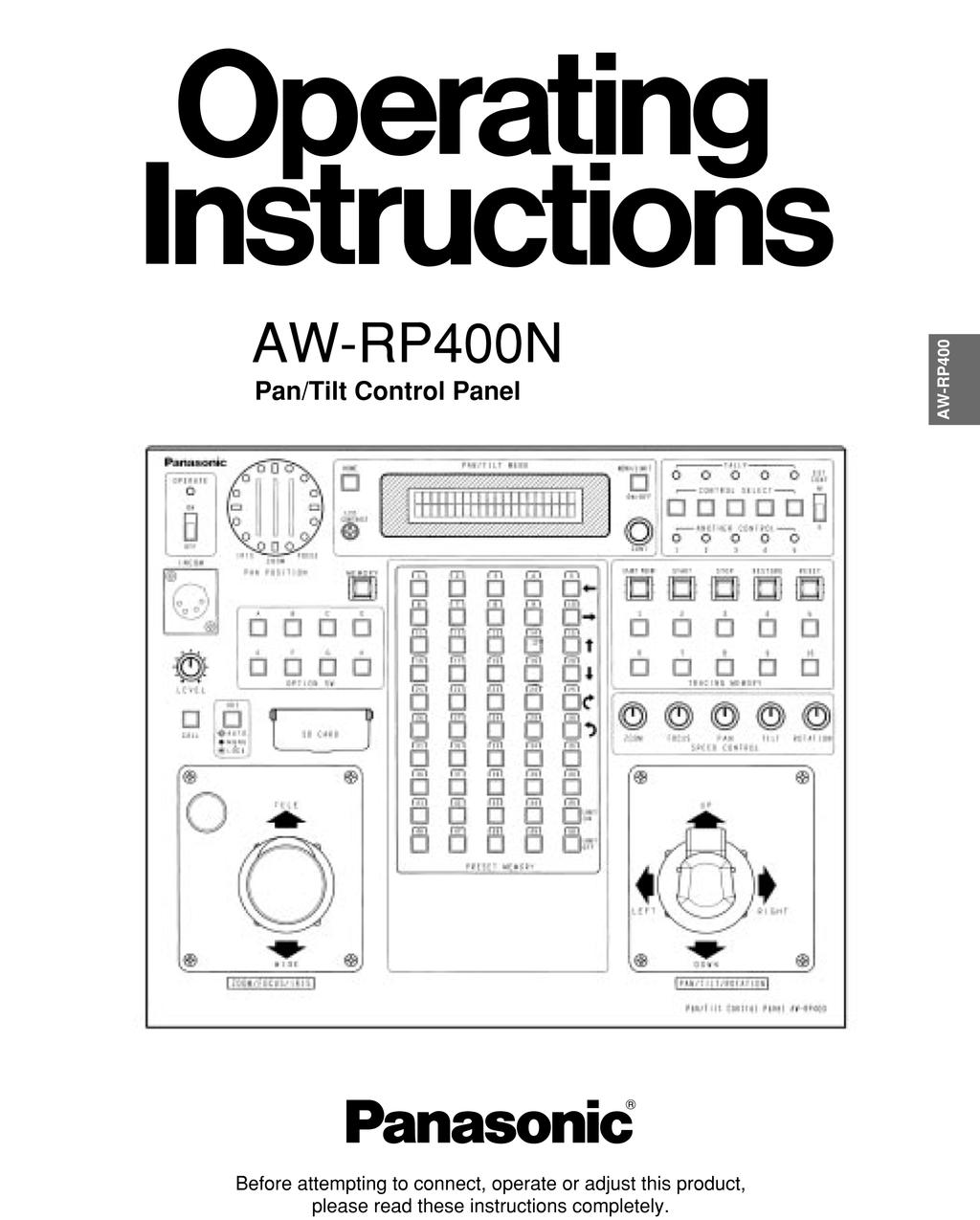
2 Pan/Tilt Control Panel AW-RP400 Introduction This pan/tilt control panel enables up to five AW-PH400 indoor pan/tilt heads to be controlled. By connecting the AW-CB400 remote operation panel or WV-CB700A remote control box to the control panel, the convertible cameras mounted on the pan/tilt heads can be controlled at the same time. By installing an additional control panel, two of the five units in the pan/tilt head system can be controlled at the same time. Up to ten tracing memories can be accommodated. Up to 50 preset memories can be set. The connection distance between the control panel and pan/tilt head system can be extended up to a maximum of 500 meters. NOTE The AW-RP400 cannot be used to control the model AW-PH300, AW-PH300A, AW-PH350, AW-PH500 or AW-PH600 pan/tilt heads. Before using the control panel, the movement range (limiters) of the pan/tilt head system must be set without fail. When the AW-RP400 control panel is to be discarded at the end of its service life, ask a specialized contractor to dispose of it properly in order to protect the environment. Accessories Zoom switch... 1 Plug (D-SUB 15-pin) for tally/incom system... 1 set Rack-mounting adaptors... 2 Mounting screws (M4!8 mm)
3 Parts and their function Pan/Tilt Control Panel AW-RP400 $ Front panel ; < = A B C D E F G H I J K AW-RP : L 1 EXT CONT [M/S] switch This switch is normally kept at the [M] (master) position. When an additional AW-RP400 control panel has been installed, set the EXT CONT switch on the additional unit to [S] (slave). If no additional AW-RP400 control panel is going to be installed, the EXT CONT switch on this control panel must be kept at the [M] (master) position without fail. 2 OPERATE lamp This lights up green when the (3) OPERATE switch is at ON. It goes off when the switch is set to OFF. 3 OPERATE [OFF/ON] switch When this switch is set to [ON], the power supply from the connected pan/tilt heads to the cameras is turned on, and system control is enabled. When it is set to [OFF], the power supply from the connected pan/tilt heads to the cameras is turned off. NOTE The centering of the joystick and zoom switch is adjusted when the OPERATE switch has been set to [ON]. Therefore, do not touch the joystick or zoom switch while this switch is at the [ON] position. When an additional AW-RP400 control panel is installed and used, it will not be possible to exercise control from the slave control panel unless the OPERATE switches not only on the slave control panel but on the master control panel as well are set to [ON]. Remember to set the OPERATE switch on the slave control panel to [ON] first before setting the OPERATE switch on the master control panel to [ON]. 4 INCOM jack The INCOM (inter-communication) headset is connected here. 5 LEVEL control Use this to adjust the volume of the headset s receiver. 6 CALL button When this button is pressed, the buzzer of the connected control panel sounds, and the CALL button lamp lights. 23
4 Pan/Tilt Control Panel AW-RP400 Parts and their function 7 IRIS [AUTO/MANU/LOCK] button Use this to select the method for adjusting the lens iris of the cameras in the currently selected pan/tilt head system. Each time it is pressed, the setting is switched in the sequence of AUTO, MANU and LOCK. AUTO: The cameras automatically adjust the lens iris in accordance with the light quantity, and the IRIS button lamp lights. MANU: The lens iris is adjusted manually using the IRIS dial. At this setting, the IRIS button lamp is off. LOCK: The lens iris is locked at the manually adjusted setting. It does not move even when the (9) IRIS dial is turned. In this status, the IRIS button lamp flashes slowly. While MANU or LOCK is selected, the IRIS button lamp starts flashing quickly when the IRIS dial is turned: this indicates that the lens iris cannot be controlled even when the (9) IRIS dial is turned. The IRIS button on the control panel does not work when the WV-CB700A remote control box is connected to the control panel. Select AUTO or MANU using the IRIS [AUTO/MAN] button on the WV-CB700A. 8 SD CARD slot This slot is where the SD memory cards are inserted. The pan/tilt head and camera setting can be stored on these cards. 9 IRIS dial The lens iris can be adjusted by turning this dial while the (7) IRIS [AUTO/MANU/LOCK] button is set to MANU. The iris is opened by turning the dial clockwise and stopped down by turning it counterclockwise. The IRIS dial on the control panel does not work when the WV-CB700A remote control box is connected to the control panel. Adjust the iris using the IRIS control on the WV-CB700A. : ZOOM lever/focus dial Use the ZOOM lever to adjust the lens zoom. The TELE (telephoto) and WIDE (wide angle) settings are established by the direction in which the lever is tilted; the zooming speed is adjusted by the angle to which the lever is tilted. The lens is focused using the FOCUS dial on the top of the lever. ; PAN POSITION indicator Sixteen LEDs are used to display the position of the pan/tilt head in the horizontal rotational direction for 200 degrees to the left or right. When the pan/tilt head is rotated to the right by more than 180 degrees up to 200 degrees, the 180-degree LED flashes, and LEDs on its left light. Conversely, when the pan/tilt head is rotated to the left by more than 180 degrees up to 200 degrees, the 180- degree LED flashes, and LEDs on its right light. < IRIS indicator The position of the lens iris in the currently selected pan/tilt head system is indicated by a 6-step display (CLOSE > OPEN). = ZOOM indicator The position of the lens zoom in the currently selected pan/tilt head system is indicated by a 6-step display (WIDE > TELE). > FOCUS indicator The position of the lens focus in the currently selected pan/tilt head system is indicated by a 6-step display (NEAR > FAR).? OPTION switches [A to H] The NOT USE, DEF, WIP, HEATER/FAN, LAMP, OPTION, ND, EXT and AF functions can be allocated to OPTION switches A to H by menu HOME button Press this to move the pan/tilt head and roll unit to the home position. A LCD CONTRAST control Use this to adjust the contrast of the LCD panel. 0o 90 to the left 90 to the right 180 to the left or right 24
5 Parts and their function Pan/Tilt Control Panel AW-RP400 B MEMORY button When one of the (C) PRESET MEMORY selection buttons [1] to [50] is pressed while holding down the MEMORY button, the settings of the pan/tilt head system can be registered in that PRESET MEMORY selection button. The MEMORY button flashes if the pan/tilt head selected by the (H) CONTROL SELECT button is not connected or its power has not been turned on. C PRESET MEMORY selection buttons [1] to [50] Use these buttons to call the settings registered in them. When data has been registered in the tracing memories, the recording/play time displays appear. D LCD panel The current setting statuses are displayed on this panel. E MENU/LIMIT button Hold down this button for two or more seconds to turn the setting menu ON or OFF. When (C) PRESET MEMORY selection button [5], [10], [15], [20], [25] or [30] is pressed while holding down the MENU/LIMIT button, ON/OFF control over the limiters can be exercised. F CONT dial This is used for the setting menu operations. G TALLY lamps [1] to [5] When tally signals are supplied to the (O) TALLY/INCOM connectors [1] to [5] on the rear panel, the lamps with the numbers corresponding to those connectors light up. When tally signals are supplied to the tally connectors [1] to [5] of the AW-CB400 remote operation panel, if this panel is connected to the pan/tilt control panel, the lamps with the numbers corresponding to those connectors also light up. H CONTROL SELECT buttons [1] to [5] The (R) CONTROL OUT TO PAN/TILT HEAD [P1] to [P5] connectors on the rear panel can be selected by pressing buttons [1] to [5]. The button lamps corresponding to the numbers of the buttons selected light, and the selected pan/tilt head systems can be controlled. When the (S) MONI SEL OUT connector on this control panel is connected to the MONI SEL IN connector on the AW-RC400 cable compensation unit, the images of the camera connected to the MONI1 or MONI2 connector on the AW-RC400 can be output. When two AW-RP400 control panels are connected, the combination of the control panels which select the monitor output can be set on the menu. I ANOTHER CONTROL lamps [1] to [5] When another AW-RP400 control panel is connected, these lamps indicate the numbers of the pan/tilt head systems selected by the additional AW-RP400 control panel. J TRACING MEMORY [START POINT, START, STOP, RESTORE, RESET, 1 to 10] buttons Use these for the tracing memory operations. For details on operation, refer to the tracing memory section. K SPEED controls [ZOOM/FOCUS/PAN/TILT/ROTATION] These enable the pan/tilt head, lens and roll unit control speeds to be adjusted. By turning these controls as far as they will go in the counterclockwise direction, operation of the pan/tilt heads and lenses can be prevented even when control is exercised using the joystick, etc. L PAN/TILT lever/rotation control switch Use these to adjust the direction of the pan/tilt heads. When the lever is tilted to the left or right, the pan/tilt heads move toward the left or right; when it is tilted up or down, they move upward or downward. The movement speed can be adjusted by the angle to which the lever is tilted. Further, the angle of the AW-RL400 roll unit can be adjusted using the ROTATION control switch on the front of the lever. By pressing the top part of the ROTATION control switch, the roll unit rotates clockwise; by pressing the bottom part, it rotates counterclockwise. The speed of the rotation changes in accordance with the amount of pressure applied. AW-RP400 25
6 Pan/Tilt Control Panel AW-RP400 Parts and their function $ Rear panel N O P Q M R S T U M EXT CONT IN/OUT connectors When an additional AW-RP400 control panel is to be provided, connect these connectors on the two AW-RP400 control panels using a 10BASE-T (equivalent to UTP category 5) straight cable. Master control panel AW-RP400 Slave control panel AW-RP400 O TALLY/INCOM connector Connect this to the TALLY/INCOM connector on the video switcher or other unit. When the TALLY input connector is set to the GND level, the TALLY lamp on the control panel or pan/tilt head lights. Do not apply a voltage in excess of 5V to this connector. EXT CONT IN EXT CONT IN ?>=<;:9 Pin layout as seen from the back panel of AW-RP400 EXT CONT OUT 10BASE-T 10BASE-T straight cable EXT CONT OUT NCAMERA CONTROL IN FROM RCB [P1] to [P5] connectors Connect the WV-CB700A remote control boxes to these connectors. The cameras installed on the pan/tilt heads corresponding to the ports where the WV-CB700A boxes have been connected can then be controlled. When even one WV-CB700A box is connected, the cameras cannot be controlled from the AW-CB400 remote operation panel even if the AW-CB400 is connected. Pin No. Signal name 1 TALLY1 9 TALLY2 2 TALLY3 10 TALLY4 3 TALLY5 11 TALLY GND MIC+ 14 MIC 7 INCOM GND 15 SP 8 SP+ Use the accessory plug (D-SUB 15-pin) to connect the tally/incom signals to the system. Connect a 4-wire INCOM system to the INCOM connector. When an additional control panel has been provided or when the AW-CB400 remote operation panel has been connected, the tally or INCOM function of all the units will take effect if tally or INCOM signals are connected to one of the units. 26
7 Parts and their function Pan/Tilt Control Panel AW-RP400 P REMOTE connector Connect an external unit to this connector to control the pan/tilt head systems from a PC or other external unit. Connect the connector to the PC using the AW-CA50T9 RS-232C cable. Q DC 12V IN socket Connect the AW-PS505 AC adaptor (sold separately) to this socket. RCONTROL OUT TO PAN/TILT HEAD [P1] to [P5] connectors Connect these connectors to the IP/RP connectors on the AW-PH400 indoor pan/tilt heads using 10BASE-T (equivalent to UTP category 5) straight cables. The cables can be extended up to a maximum of 500 meters. S MONI SEL OUT connector Connect this connector to the MONI SEL OUT connector on the AW-RC400 cable compensation unit using a 10BASE-T (equivalent to UTP category 5) straight cable. You can monitor the images of the system selected by the AW-RP400 from the MONITOR1 connector on the AW-RC400 and the images of the system selected by the AW-CB400 from the MONITOR2 connector on the AW-RC400. If two AW-RP400 units are connected, you can monitor the images of the system selected by the master AW-RP400 from the MONITOR1 connector on the AW-RC400 and the images of the system selected by the slave AW-RP400 from the MONITOR2 connector on the AW-RC400. AW-RP400 T CAMERA CONTROL IN FROM ROP connector Connect the AW-CB400 remote operation panel to this connector using the connecting cable packed with the AW-CB400. The cameras installed on the pan/tilt heads can now be controlled from the AW-CB400. U Ground terminal Connect this terminal to ground. 27
8 Pan/Tilt Control Panel AW-RP400 Menu settings $ Operation method 1 The menu setting items are displayed when the MENU/LIMIT switch is held down for two or more seconds. AW-RP400 P/T CONTROL PANEL 2 If nothing appears on the bottom line of the LCD display, turn the CONT dial to select a menu item. PRIORITY ; 3 When the CONT dial is pressed, what has been set appears on the bottom line. If more than one setting is involved in the menu item, the settings on the bottom line are switched each time the dial is pressed. ; DIRECTION SET ; DIRECTION PAN NORMAL 4 When a setting is displayed, the setting can be changed by turning the CONT dial. 5 Press the CONT dial successively: all the detailed settings come to an end, and the display on the bottom line is cleared, enabling another menu item to be selected. 6 To exit the setting menu, hold down the MENU/LIMIT switch for two or more seconds. Even when a setting is displayed on the bottom line of the LCD display, the menu is exited when the MENU/LIMIT switch is held down for two or more seconds. ; DIRECTION TILT NORMAL ; DIRECTION TILT REVERSE ; DIRECTION ; AW-RP400 P/T CONTROL PANEL 28
9 Menu settings Pan/Tilt Control Panel AW-RP400 $ List of menu items and settings Menu item Setting Description Initial value PRIORITY MASTER, SLAVE MASTER DIRECTION PAN TILT ZOOM FOCUS NORMAL, REVERSE NORMAL IRIS ROTATION TILT RANGE 190, SPEED WITH ZOOM POS. OFF, 1, 2, 3 OFF MEMORY LENGTH 60s, 120s, 300s, 600s 60s PRESET SPEED 1 to IRIS CONTROL BOTH, RP400, CB400 BOTH ROTATION SWITCH ROTATION, FOCUS, ZOOM, IRIS ROTATION OPTION SWITCH A B C D NOT USE, DEF, WIP, HEATER/FAN, NOT USE E LAMP, OPTION, ND, EXT, AF F G H CONTROL SELECT MODE INTERLOCK, UN-INTERLOCK INTERLOCK BUZZER OFF, ON ON AUTO RUN START No. 1 to 50 1 END No. 1 to INTERVAL 1s to 30s 1s OPERATE STOP, RUN STOP SD CARD STORE, LOAD AW-RP400 PRIORITY (MASTER/SLAVE) When two AW-RP400 pan/tilt control panels have been connected, the priority of the CONTROL SELECT buttons is to be set. When MASTER is selected as the setting, the master AW-RP400 has priority; when SLAVE is selected, the slave AW-RP400 has priority. If the AW-RP400 control panel with a high priority has selected the pan/tilt heads, which were selected by the AW-RP400 control panel with a low priority, the CONTROL SELECT button lamps on the AW-RP400 control panel with the low priority start flashing to indicate that the control rights have been ceded to the other control panel. This setting is performed using the master AW-RP400 control panel. 29
10 Pan/Tilt Control Panel AW-RP400 Menu settings DIRECTION settings (PAN, TILT, ZOOM, FOCUS, IRIS, ROTATION: NORMAL/REVERSE) When the lever or dial is operated, the DIRECTION menu item enables the operational direction of PAN, TILT, ZOOM, FOCUS, IRIS or ROTATION to be set as the user desires. PAN: TILT: ZOOM: FOCUS: When NORMAL is selected, the pan/tilt head moves toward the left when the PAN/TILT lever is tilted to the LEFT and toward the right when it is tilted to the RIGHT. When REVERSE is selected, the head moves in the opposite direction. When NORMAL is selected, the pan/tilt head moves upward when the PAN/TILT lever is tilted toward UP and down when it is tilted toward DOWN. When REVERSE is selected, the head moves in the opposite direction. When NORMAL is selected, the lens zoom moves toward the telephoto end when the ZOOM lever is tilted toward TELE and toward the wide-angle end when it is tilted toward WIDE. When REVERSE is selected, the zoom moves in the opposite direction. When NORMAL is selected, the lens focus moves toward FAR when the FOCUS dial is turned clockwise and toward NEAR when it is turned counterclockwise. When REVERSE is selected, the lens focus moves in the opposite direction. IRIS: When NORMAL is selected, the lens iris moves toward open when the IRIS dial is turned clockwise and toward closed when it is turned counterclockwise. When REVERSE is selected, the lens iris moves in the opposite direction. ROTATION: When NORMAL is selected, the pan/tilt head moves clockwise when the top of the ROTATION control switch is pressed and counterclockwise when the bottom is pressed. When REVERSE is selected, the head moves in the opposite direction. TILT RANGE setting (190/300 degrees) This menu item is used to set the tilting range of the AW-PH400. Normally, the 190 degrees setting is used. SPEED WITH ZOOM POS. setting (OFF/1/2/3) At the OFF setting, the pan and tilt speed does not change in accordance with the zoom position. At the 1, 2 or 3 setting, the panning and tilting of the pan/tilt head slows down as the zoom approaches the telephoto end, making it easier to adjust the pan or tilt position even at the telephoto end. The higher the number selected for the setting, the slower the pan and tilt speed at the telephoto end, and the easier it is to adjust the position using a zoom lens with a high magnification rate. PRESET SPEED setting (1 to 25) During preset memory data play, this menu item enables the movement speed to the preset positions to be set to one of 25 steps. The higher the setting, the faster the movement speed to the preset positions; conversely, the lower the setting, the slower the movement speed. IRIS CONTROL setting (BOTH/RP400/CB400) When the AW-CB400 remote operation panel has been connected to the AW-RP400 control panel, this menu item is used to set which control panel is to be used to adjust the lens iris. At the BOTH setting, the lens iris can be controlled from both the AW-RP400 and AW-CB400. At the RP400 setting, it can be controlled only from the AW-RP400; similarly, at the CB400 setting, it can be controlled only from the AW-CB400. ROTATION SWITCH setting (ROTATION/FOCUS/ZOOM/IRIS) This menu item enables ROTATION, FOCUS, ZOOM or IRIS to be selected as the function to be controlled by the ROTATION switch. 30
11 Menu settings Pan/Tilt Control Panel AW-RP400 OPTION SWITCH A to H settings (NOT USE / DEF / WIP / HEATER/FAN / LAMP / OPTION / ND / EXT / AF) The following functions can be allocated to OPTION buttons A to H. Different functions can be allocated for different pan/tilt heads. NOT USE: DEF: The button is disabled. This controls the ON and OFF states of the defroster function when using a pan/tilt head system equipped with this function. Each time the button is pressed, ON is switched to OFF or vice versa. When the defroster function is ON, the lamp of the button to which this function has been allocated is lighted; when it is OFF, the lamp is off. WIP: This controls the ON and OFF states of the wiper function when using a pan/tilt head system equipped with this function. Each time the button is pressed, ON is switched to OFF or vice versa. When the wiper function is ON, the lamp of the button to which this function has been allocated is lighted; when it is OFF, the lamp is off. HEATER/FAN: This controls the ON and OFF states of the heater/fan function when using a pan/tilt head system equipped with this function. Each time the button is pressed, ON is switched to OFF or vice versa. When the heater/fan function is ON, the lamp of the button to which this function has been allocated is lighted; when it is OFF, the lamp is off. LAMP: OPTION: ND: EXT: AF: This controls the ON/OFF switching of the power from the AC outlet which is used for the AC adaptor s lamp when using an AC adaptor for a pan/tilt head provided with a lamp control function. Each time the button is pressed, ON is switched to OFF or vice versa. When the lamp is ON, the button to which the function is allocated lights; when it is OFF, the button goes off. If the lamp fails at the ON setting, the button blinks. This controls the short-circuit and open-circuit states of the AC adaptor s OPTION CONTROL OUT connector when using an AC adaptor for a pan/tilt head system equipped with the OPTION switch control function. Each time the button is pressed, short circuit is switched to open circuit or vice versa. When short-circuited, the lamp of the button to which this function has been allocated is lighted; when open-circuited, the lamp is off. This controls the ON and OFF states of the ND filter when using a lens equipped with an ND filter. Each time the button is pressed, ON is switched to OFF or vice versa. When the ND filter is ON, the lamp of the button to which this function has been allocated is lighted; when it is OFF, the lamp is off. This controls the ON and OFF states of the extender when using a lens equipped with an extender. Each time the button is pressed, ON is switched to OFF or vice versa. When the extender is ON, the lamp of the button to which this function has been allocated is lighted; when it is OFF, the lamp is off. This controls the ON and OFF states of the auto focus function when using a lens equipped with this function. Each time the button is pressed, ON is switched to OFF or vice versa. When the auto focus function is ON, the lamp of the button to which this function has been allocated is lighted; when it is OFF, the lamp is off. AW-RP400 MEMORY LENGTH setting (60s/120s/300s/600s) This menu item is used to set the tracing memory data recording time and the number of memories. 60s : 60 sec.! 10 memories 120s : 120 sec.! 5 memories 300s : 300 sec.! 2 memories 600s : 600 sec.! 1 memory When data has already been registered in a tracing memory, the setting for the recording time and number of memories cannot be changed. To reset a setting, delete the registered data in the tracing memory first. 31
12 Pan/Tilt Control Panel AW-RP400 Menu settings CONTROL SELECT MODE setting (INTERLOCK/UN-INTERLOCK) This menu item is for selecting the method used to select the pan/tilt head and camera when the AW-CB400 remote operation panel has been connected to the AW-RP400 control panel. INTERLOCK: When the pan/tilt head and camera system are selected by the AW-RP400 or AW-CB400, the same system is selected by the other unit as well. UN-INTERLOCK: A different pan/tilt head and camera system can be selected by the AW-RP400 and AW-CB400. When two AW-RP400 units are connected, INTERLOCK is always set regardless of this menu item s setting. BUZZER setting (OFF/ON) This menu item is used to select ON or OFF for the buzzer inside the control panel. The buzzer does not sound at the OFF setting. The buzzer sounds when the CALL button has been pressed or when a tracing memory operation (record, play or change) is started, suspended or ended. AUTO RUN setting (START No., END No., INTERVAL) This menu item enables the presets of the pan/tilt head to be repeated automatically. START No. (1 to 50): This sets the first number of the preset to be repeated. END No. (1 to 50): This sets the last number of the preset to be repeated. INTERVAL (1s to 30s): This sets the stop time at the preset position. Up to 30 seconds can be set in 1-second increments for the stop time. OPERATE (STOP/RUN): When RUN is selected, the presets from the START No. to STOP No. are played repeatedly; when STOP is selected, operation stops. When the PAN/TILT lever is operated, STOP is selected automatically, and operation stops. SD CARD setting The menu setting data of this control panel, the preset memory data of the pan/tilt heads and the setting data of the cameras can be stored on SD memory cards. If the MENU button is pressed while STORE is displayed, the display changes to EXECUTE, and the settings are saved on the SD memory card. The process is completed when the EXECUTE display is cleared from the screen. If the MENU button is pressed while LOAD is displayed, the display changes to EXECUTE, and the settings on the SD memory card are called and loaded into the unit, pan/tilt head and camera. The process is completed when the EXECUTE display is cleared from the screen. Confine the use of the SD memory card to this unit only, and refrain from using it with a personal computer, digital camera or other device. Do not eject the SD memory card, turn off the power or set the OPERATE switch to OFF while EXECUTE is displayed. The tracing memory data is not stored. 32
13 How to mount the AW-RP400 in a rack Pan/Tilt Control Panel AW-RP400 <NOTE> The AW-RP400 is 320 mm wide. If it is to be installed in a full-size rack (which accommodates units totaling 420 mm in width), provide panels or other parts to supplement the AW-RP400 s width so that it will fill the rack width-wise. If the AW-RP400 is joined to the AW-CB400, the resulting width will be equivalent to that of the full width of the rack (which accommodates units totaling 420 mm in width). 1 Use the accessory mounting screws (M4!8 mm) to attach the rack-mounting adaptors. Rack-mounting adaptor 320mm AW-RP400 AW-RP400 Accessory mounting screws (M4!8 mm) 4 pcs 33
14 Pan/Tilt Control Panel AW-RP400 How to change the position of the connector panel The position of the connector panel can be changed from the rear panel to the bottom panel. Before changing the position, turn off the power. Screws!5 (bottom panel) 1 Remove the five bottom panel screws, and remove the blank panel. Remove the blank panel. Screws!5 (rear panel) 2 Remove the five rear panel screws, and remove the connector panel. Remove the connector panel. Screws!5 (rear panel) 3 Secure the blank panel to the rear panel using the screws. Blank panel 4 Remove the two rubber feet from the blank panel. Remove the two rubber feet. Screws!5 (bottom panel) 5 Secure the connector panel to the bottom panel using the screws. Connector panel 34
15 How to replace the zoom switch Pan/Tilt Control Panel AW-RP400 Before replacing the zoom switch, turn off the power. 1 Remove the four screws that secure the zoom lever. Screws!4 AW-RP400 2 Pull out the zoom lever, disconnect the two cables from the circuit board inside, and remove the zoom lever. 3 Plug the two cables extending from the zoom switch into the connectors on the circuit board inside. 4 Secure the zoom switch using the four screws. Screws!4 35
16 Pan/Tilt Control Panel AW-RP400 Replacing the consumable parts The joysticks and zoom switch are consumables. Replace them if they are not working properly. Ask your dealer to do the replacement work. 36
17 Specifications Pan/Tilt Control Panel AW-RP400 Supply voltage: Power consumption: DC 12.0 V Approx. 13 W 1 indicates safety information. Input connectors DC 12V IN: XLR, 4 pins CONTROL IN FROM ROP: D-SUB 29-pin, cable supplied with AW-CB400 remote operation panel CONTROL IN FROM RCB: 10-pin round connector, cable supplied with WV-CB700A EXT CONT IN: RJ45, additional AW-RP400 control signal input; 10BASE-T straight cable (UTP category 5), max. 500 meters REMOTE: 50-pin D-SUB connector, external control input, AW-CA50T9 Output connectors CONTROL OUT TO PAN/TILT HEAD: RJ45, pan/tilt head control signal output; 10BASE-T straight cable (UTP category 5), max. 500 meters MONI SEL OUT: RJ45, monitor switching signal output; 10BASE-T straight cable (UTP category 5), max. 50 meters EXT CONT OUT: RJ45, additional AW-RP400 control signal output; 10BASE-T straight cable (UTP category 5), max. 500 meters AW-RP400 Input/output connectors INCOM (top panel): TALLY/INCOM: Switch functions: Adjustment functions: XLR, 4 pins D-SUB, 15-pin TALLY: Contact input (Do not apply a voltage in excess of 5V to this connector.) INCOM: 4-wire system Master/slave switching, OPERATE control, home position, menu/limit switch, optional function operations, pan/tilt head selection, lens iris AUTO/MANU/LOCK switching, preset memory data operations, tracing memory data operations, call LCD contrast, INCOM level, lens iris, zoom, focus, pan/tilt/rotation, zoom speed, focus speed, pan speed, tilt speed, rotation speed, menu settings Ambient operating temperature: 14 F to 113 F ( 10 C to +45 C) Storage temperature: Ambient operating humidity: Dimensions (W!H!D): Weight: Finish: 4 F to 140 F ( 20 C to +60 C) 30% to 90% (no condensation) 12-5/8!3-3/8!10-1/2 (320!85!266 mm) Approx. 8.4 lbs (3.8 kg) Color resembling Munsell 3.5 paint Weight and Dimensions indicated above are approximate. Specifications are subject to change without notice. 37
18 Cable Compensation Unit AW-RC400 Introduction The AW-RC400 is capable of providing cable compensation for analog composite, analog Y/C or analog component signals in five channels up to 500 meters (when the BELDEN 8281 connecting cable or its equivalent is used). It features a 5µs advance function for the sync signals in order to provide easy support for a system (another cable compensation unit is required) in which the coaxial cable connected between this AW-RC400 cable compensation unit and the camera is longer than 500 meters. NOTE Input either sync signals to the sync signal input connector on the AW-RC400 cable compensation unit or input video signals to one of the video channels (input composite signals or Y signals with sync to video input connector 1). If neither of these signals is input, the monitor selection will not be controlled. The AW-RC400 provides cable compensation for the three Y, Pr and Pb signal channels by means of a single control. This means that the Y, Pr and Pb signals cannot be adjusted separately. In the same way, the Y and C signals cannot be adjusted separately. The AW-RC400 is a cable compensation unit and, as such, it does not come with signal conversion functions (for converting component signals into composite signals, for instance). When the cable compensation unit is to be discarded at the end of its service life, ask a specialized contractor to dispose of it properly in order to protect the environment. Accessories Rack-mounting adaptors... 2 Mounting screws (M4!8 mm)
19 Parts and their function Cable Compensation Unit AW-RC >=<?@A ; : 9 B Front panel Rear panel 6 C 87 1 Power LED This lights up green when the (2) POWER switch is set to ON while a DC 12V voltage is supplied to the (7) DC 12V IN socket. 2 POWER switch Set this to ON to turn on the cable compensation unit s power. Part of the power supply circuitry will still operate even when the power switch is at the OFF position. To turn off the power completely, disconnect the AC adaptor. 3 Cable length setting switches [0 to 5] Set these switches according to the length of the coaxial cable connected. [0] is used to provide the minimum amount of cable compensation, and [5] the maximum amount. As a general guideline, set to [1] if the coaxial cable is 100 meters long, and [2] if it is 200 meters long. 4 Y LEVEL control Use this to adjust the output level of the cable compensation output signals (video output). 5 F RESPONSE control Use this to adjust the amount of cable compensation (frequency response compensation) for the cable compensation output signals. 6 SHORT/LONG selector switch This is normally used at the SHORT position. Set it to LONG if the coaxial cable from the camera is a long one and the camera s sync adjustment range is insufficient, or if the cable compensation unit is used as part of a system (another cable compensation unit is required) in which the coaxial cable (BELDEN 8281 or equivalent) connected to the camera is longer than 500 meters. 7 DC 12V IN socket This is the power input socket. Connect the AW-PS301 AC adaptor (sold separately) here. 8 MONI SEL IN connector Control signals for selecting the video signals output to the MONITOR1 or 2 connector are supplied to this connector. Connect it to the MONI SEL OUT connector on AW-RP400 pan/tilt control panel using a 10BASE-T straight cable (equivalent to UTP category 5). It is then possible to output the video signals of the camera selected by the AW-RP400 or the AW-CB400 remote operation panel which is connected to the AW-RP400, to the MONITOR1 or MONITOR2 connector. 9 G/L IN connectors The sync signals (black burst signals) are input here. These connectors are automatically terminated internally by a 75-ohm resistance. The top and bottom connectors have the same specifications, and the signals can be connected to either one. The termination is released if BNC cables are connected to both input connectors (when they are used in a loop-through configuration). : G/L OUT connectors [1 to 5] The genlock signals supplied to the G/L IN connector can be distributed and output to five cameras. Use sync signal outputs 1 to 5 to correspond to video signal channels 1 to 5. The signals of sync signal output connector 1 are supplied to the camera connected to video input connector 1. AW-RC400 39
20 Cable Compensation Unit AW-RC400 Parts and their function ; MONITOR1, 2 connectors The video signals of the cameras selected by the AW-RP400 pan/tilt control panel or the AW-CB400 remote operation panel which is connected to the AW-RP400 are output from these connectors. The output signals are cable-compensated signals of the same type as the input signals. For instance, if a channel to which composite signals have been input is selected, these composite signals will be cable-compensated and output. < Y/VIDEO IN connectors [1 to 5] The analog video signals are input to these connectors. They are terminated internally by a 75-ohm resistance. Either Y (component signals or Y of the Y/C signals with sync) or VIDEO (composite) signals are supplied. B AC adaptor storage space The AC adaptor can be stored here when the ambient temperature in the location where the cable compensation unit has been installed is under 86 F (30 C). Remove the two screws, and remove the storage space cover. Stow the AW-PS301 AC adaptor in such a way that the pull-out cable will not be stressed. Trouble will occur in the AC adaptor if the ambient temperature exceeds 86 F (30 C), in which case it should not be stored in the space. C Cable clamp This is used to clamp the cable of the AW-PS301 AC adaptor in place and prevent it from coming loose. = Pr/C IN connectors [1 to 5] The analog video signals are input to these connectors. They are terminated internally by a 75-ohm resistance. Either Pr (R-Y among the component signals) or C (C of the Y/C signals) signals are supplied. > Pb IN connectors [1 to 5] The analog video signals are input to these connectors. They are terminated internally by a 75-ohm resistance. The Pb (B-Y among the component signals) signals are supplied.? Y/VIDEO OUT connectors [1 to 5] The analog video signals are output from these connectors. Cable-compensated Y or VIDEO (composite) signals that are in accordance with the input signals are output. Y signals are output if component Y signals have been input to the Y/VIDEO IN connectors [1 to 5], and composite signals are output if composite signals have been Pr/C OUT connectors [1 to 5] The analog video signals are output from these connectors. Cable-compensated Pr or C signals that are in accordance with the input signals are output. Pr signals are output if Pr signals have been input to the Pr/C IN connectors [1 to 5], and C signals are output if C signals have been input. A Pb OUT connectors [1 to 5] The analog video signals are output from these connectors. Cable-compensated Pb signals are output if Pb signals have been input to the Pb IN connectors [1 to 5]. 40
21 How to mount the AW-RC400 in a rack Cable Compensation Unit AW-RC400 Use the accessory rack-mounting adaptors and accessory mounting screws (M4!8 mm) to mount the unit in a rack. POWER switch 1 Set the POWER switch at the OFF position to turn off the power. 2 Remove four feet on the bottom of the unit. Remove four feet. Rack-mounting adaptor AW-RC400 3 Place the rack-mounting adaptors to the both ends of the unit, and fix it using four mounting screws. Mounting screws 41
22 Cable Compensation Unit AW-RC400 Specifications Supply voltage: Power consumption: DC 12.0 V Approx. 9 W 1 indicates safety information. Input connectors DC 12V IN: G/L IN: VIDEO/Y, Pr/C, Pb: MONI SEL IN: Output connectors G/L OUT: VIDEO/Y, Pr/C, Pb: MONITOR OUT1/2: For connecting optional accessory AC adaptor (AW-PS301) BNC!2, automatically terminated by 75-ohm resistance, loop-through output, black burst BNC!3 (5 sets), 75-ohm termination Composite Y/C Component (Y/Pr/Pb) RJ45 Connecting cable: 10BASE-T straight cable (UTP category 5), max. 50 meters BNC!5, 75-ohm output, BELDEN 8281 connecting cable, max meters BNC!3 (5 sets), 75-ohm output Composite Y/C Component (Y/Pr/Pb) (Cable compensation adjustment is required) BNC!3 (2 sets), 75-ohm output Switch and adjustment functions: Power ON/OFF; cable length setting 0/1/2/3/4/5; sync signal setting SHORT/LONG; cable compensation amount adjustment; video level adjustment Ambient operating temperature: 14 F to 113 F ( 10 C to +45 C) Storage temperature: Ambient operating humidity: Dimensions (W!H!D): Weight: Finish: 4 F to 140 F ( 20 C to +60 C) 30% to 90% (no condensation) 16-9/16!3-7/16!9-13/16 (420!88!250 mm) Approx. 8.2 lbs (3.7 kg) AV ivory paint (color resembling Munsell 7.9Y6.8/0.8) Weight and Dimensions indicated above are approximate. Specifications are subject to change without notice. 42
23 Introduction The AW-RL400 roll unit enables a camera to be rotated when it is used in combination with the AW-PH400 indoor pan/tilt head. NOTE Roll Unit AW-RL400 Since the roll unit causes the camera to rotate, the user should ensure that all the wiring such as the camera cable and lens cable will not become entangled when the roll unit is operated. When the roll unit is to be discarded at the end of its service life, ask a specialized contractor to dispose of it properly in order to protect the environment. Accessories Pan/tilt head connecting cable... 1 AW-RL400 43
24 Roll Unit AW-RL400 Parts and their function Rotary ring 2 Camera mounting screw (U1/4-20UNC) After mounting the camera, secure it firmly using this screw. 3 Camera mounting plate (A) (B) Mount the camera on this plate using the camera mounting screws. 5 Roll unit anchoring screw holes This is where the roll unit is secured to the rotary arm of the pan/tilt head. 6 Pan/tilt head connector Connect this to the OPTION connector on the pan/tilt head using the pan/tilt head connecting cable supplied. 4 Camera mounting plate anchoring screws After mounting the camera on the camera mounting plate, anchor it to the roll unit using these screws. 44
25 Installation Roll Unit AW-RL400 1 Attach the pan/tilt head s rotary arm to the roll unit using the three mounting screws (M5!22 mm, with flat washers, pan/tilt head accessory). 2 Attach the rotary arm to the pan/tilt head using the mounting screws (M5!22 mm, with flat washers, pan/tilt head accessory). Roll unit Rotary arm Camera mounting plate (consisting of 2 separate sub plates) AW-RL400 3 Loosen the two screws of camera mounting plate which is already installed to the roll unit. Then remove the camera mounting plate. Camera mounting plate (consisting of 2 separate sub plates) Screws When assembling the units, use the Allen key (provided), wrench and screwdriver, and secure the units by tightening the screws firmly. After mounting the units, check there is no play in the way they are mounted. 45
26 Roll Unit AW-RL400 Installation 4 Separate the camera mounting plate, which was removed in step 3, into its two sub plates. Separate the camera mounting plate into sub plate (A) and sub plate (B) by loosening the clamping screw. Clamping screw 5 Follow the steps below to mount the camera mounting sub plates, which were separated in step 4, onto the camera body. When the AW-E750, AW-E650 or AW-E350 is used as the camera (1) Remove the screw attached to camera mounting sub plate (A), and use it to mount camera mounting sub plate (B) onto the tripod mounting seat. (2) Mount camera mounting sub plate (A) onto camera mounting sub plate (B). When the AW-E655 is used as the camera (1) Mount camera mounting sub plate (A) onto the tripod mounting seat using the two camera mounting screws. Be absolutely sure to use a screwdriver or other tool to tighten the two camera mounting screws so that the camera mounting plate is secured firmly. 46
27 Installation Roll Unit AW-RL400 6 Attach the camera mounting plate to the roll unit in a way contrary to the procedure of removing it in step 3. Camera mounting plate s screws AW-RL400 7 Using the pan/tilt head connecting cable provided, connect the [OPTION] connector on the pan/tilt head connector panel and the connector on the roll unit. OPTION connector Lens cable Pan/tilt head connecting cable 8 After the roll unit, camera body and pan/tilt head have been mounted, complete the installation by mounting the lens. 9 Connect the lens cable connectors to the camera body and pan/tilt head. 47
28 Roll Unit AW-RL400 Specifications Supply voltage: Power consumption: DC 24 V Approx. 24 W 1 indicates safety information. Pan/tilt head connector: Performance: Connected to pan/tilt head using cable supplied Maximum load-bearing capability: 8.8 lbs (4 kg) Rotary range: 380 degrees (approx. ±190 degrees) Maximum operating speed: 60 degrees/sec. Repeatability: Less than ±1 degree Ambient operating temperature: 32 F to 113 F (0 C to +45 C) Storage temperature: Ambient operating humidity: Dimensions (W!H!D): Weight: Finish: 4 F to 140 F ( 20 C to +60 C) 30% to 90% (no condensation) 8-1/16!7-13/16!10-1/4 (205!198!260 mm) Approx. 8.6 lbs (3.9 kg) AV ivory paint (color resembling Munsell 7.9Y6.8/0.8) Weight and Dimensions indicated above are approximate. Specifications are subject to change without notice. 48
29 Connections Turn off the power of all the equipment before proceeding with the connections. Use the AW-PS505 as the AC adaptor for the AW-RP400 pan/tilt control panel. Use the DC cable supplied with the AW-PS505 to connect the DC 12V IN socket on the AW-RP400 with the DC 12V OUT socket on the AW-PS505. Connect the AC power cable supplied with the AW-PH400 for the AW-PH400 indoor pan/tilt head. Use the AC adaptor (optional accessory) for the AW-RC400 cable compensation unit. Use 10BASE-T straight cables to connect the IP/RP connectors on the pan/tilt heads with the CONTROL OUT TO PAN/TILT HEAD (1 to 5) connectors on the AW-RP400. The maximum extension distance is 500 meters when using UTP category 5 cables or their equivalent. Use the camera cables supplied with the pan/tilt head to connect the AW-PH400 to the convertible camera. Connect the iris control cable of the motorized zoom lens to the IRIS connector on the camera, and connect the zoom/focus cable to the LENS I/F connector on the pan/tilt head. Use either the AW-CB400 remote operation panel or WV-CB700A remote control box for camera control. The AW-CB400 and WV-CB700A cannot be used together. When using the AW-CB400, use the cable (10 m) supplied with the AW-CB400 to connect the CAMERA CONTROL IN FROM ROP connector on the AW-RP400 with the I/F CONNECTOR on the AW-CB400. Five cameras can be controlled from the AW-CB400. Power is supplied through this cable from the AW-RP400 to the AW-CB400 so the AC adaptor need not be connected to the AW-CB400. When using the WV-CB700A, use the RCB cables (2 m) supplied with the WV-CB700A to connect the CAMERA CONTROL IN FROM RCB (1 to 5) connectors on the AW-RP400 with the RCB connectors on the WV-CB700A. Only one camera can be controlled from the WV-CB700A. If there is a multiple number of cameras, one AW-CB700A will be required for each camera. It is also necessary to align the number of the CONTROL OUT TO PAN/TILT HEAD connectors connected to the cameras to be controlled with the CAMERA CONTROL IN FROM RCB connectors used to connect the WV-CB700A. Use the 10BASE-T straight cable to connect the MONI SEL OUT connector on the AW-RP400 with the MONI SEL IN connector on the AW-RC400. The maximum extension distance is 50 meters when using a UTP category 5 cable or its equivalent. By connecting these MONI SEL connectors, the video signals of the camera selected by the AW-RP400 can be output from the MONITOR1 connector and the video signals of the camera selected by the AW-CB400 can be output from the MONITOR2 connector. When the WV-CB700A is used, MONITOR2 cannot be switched. Use a coaxial cable to connect the AW-RC400 and AW-PH400. Supply the genlock signals from a unit such as a signal generator to the G/L IN connector on the AW-RC400, and connect the G/L OUT (1 to 5) connectors on the AW-RC400 with the G/L IN connectors on the pan/tilt heads. When using composite signals, connect the VIDEO connectors on the pan/tilt heads and Y/VIDEO IN connectors (1 to 5) on the AW-RC400. Also connect the Y/VIDEO OUT connectors on the AW-RC400 to switchers or monitors. When using Y/C signals, connect the Y connectors and Pr/C connectors on the pan/tilt heads to the Y/VIDEO IN connectors and Pr/C IN connectors, respectively, on the AW-RC400. Also connect the Y/VIDEO OUT connectors and Pr/C OUT connectors on the AW-RC400 to switchers or monitors. When using component signals, connect the Y connector, Pr/C connector and Pb connector on the pan/tilt head to the Y/VIDEO IN connector, Pr/C IN connector and Pb IN connector, respectively, on the cable compensation unit. Also connect the Y/VIDEO OUT connectors, Pr/C OUT connectors and Pb OUT connectors on the AW-RC400 to switchers or monitors. 49
30 Connections Motorized zoom lens Iris control Zoom/focus control AW-PH400 Indoor Pan/Tilt Head Camera cable supplied with AW-PH400 Convertible camera Pan/tilt head/camera control signals Genlock signals Video signals AC power cable supplied with AW-PH400 Video signal output AW-CB400 Remote Operation Panel AW-RP400 Pan/tilt control panel AW-RC400 Cable Compensation Unit Genlock signal input Cable supplied with AW-CB400 (AW-CB400 power and camera control signals) AW-PS505 AC adaptor AW-PS301 AC adaptor Monitor for AW-RP400 Monitor switching signals Monitor signals 1 Monitor for AW-CB400 Monitor signals 2 50
31 Example of system configuration Convertible camera Indoor Pan/Tilt Head AW-PH400 G/L Composite video or component video signals Pan/tilt head and camera control MONITOR1 MONITOR2 To switcher, monitor Genlock signals Monitor Monitor switching Monitor Cable provided with AW-CB400 AW-PS301 AC adaptor AW-RC400 Cable Compensation Unit Headset Headset AW-PS505 AC adaptor Pan/Tilt Control Panel AW-RP400 Remote Operation Panel AW-CB400 51
32 Operating procedures $ Turning on the power 1 When using one AW-RP400, set its EXT CONT [M/S] switch to the [M] position. When two AW-RP400 units are used, set the EXT CONT [M/S] switch on the AW-RP400 to which the pan/tilt head is connected to the [M] (master) position and the switch on the AW-RP400 to which the pan/tilt head is not connected to the [S] (slave) position. 2 Turn on the power. Follow the sequence below to turn on the power when one AW-RP400 is going to be used: Set the power switch of the AC adaptor used for the AW-RP400 and the AC power switch on the AW-PH400 to [ON], set the OPERATE switch on the AW-CB400 to [ON], and then set the OPERATE switch on the AW-RP400 to [ON]. Follow the sequence below to turn on the power when two AW-RP400 units are going to be used: Set the OPERATE switches of the AW-CB400 and of the AW-RP400 set as the slave to [ON], and then set the OPERATE switch on the AW-RP400 set as the master to [ON]. $ Setting the movement range (limiters) of the AW-PH400 indoor pan/tilt head If there are any objects obstructing the movement of the AW-PH400 indoor pan/tilt head in the immediate vicinity, set restrictions on the movement range (limiters: left, right, top and bottom limits of rotation). When the AW-RL400 roll unit is connected to the AW-RP400, set the movement limits (clockwise and counterclockwise limits) of the roll unit as well. Before using these units, set these limits without fail. When it is shipped, the AW-PH400 is set up to be placed on a stand or base. If it is to be suspended from the ceiling, the mounting direction switch must be set without fail. If this setting is not performed correctly, the directions of the pan/tilt operations will be reversed, and the movement range (limiter) settings of the pan/tilt head will not be stored in the memory properly. For details on the setting methods and related aspects, refer to Setting the mounting direction switch in the operating instructions for the AW-PH400. Now proceed with the settings for the AW-RP400 pan/tilt control panel. 1 Use the CONTROL SELECT buttons to select the pan/tilt head whose movement range (limiters) is to be set. 2 To set the left limit, use the PAN/TILT lever to rotate the pan/tilt head as far as the left limit which is to be set. While holding down the MENU/LIMIT button, press the PRESET MEMORY button [5]. Once the limit is set, the lamp of the PRESET MEMORY button [45] will light. To release the setting, press the PRESET MEMORY button [5] again while holding down the MENU/LIMIT button. Once the setting is released, the lamp of the PRESET MEMORY button [50] will light. 3 To set the right limit, use the PAN/TILT lever to rotate the pan/tilt head as far as the right limit which is to be set. While holding down the MENU/LIMIT button, press the PRESET MEMORY button [10]. Once the limit is set, the lamp of the PRESET MEMORY button [45] will light. To release the setting, press the PRESET MEMORY button [10] again while holding down the MENU/LIMIT button. Once the setting is released, the lamp of the PRESET MEMORY button [50] will light. 4 To set the top limit, use the PAN/TILT lever to rotate the pan/tilt head as far as the top limit which is to be set. While holding down the MENU/LIMIT button, press the PRESET MEMORY button [15]. Once the limit is set, the lamp of the PRESET MEMORY button [45] will light. To release the setting, press the PRESET MEMORY button [15] again while holding down the MENU/LIMIT button. Once the setting is released, the lamp of the PRESET MEMORY button [50] will light. 5 To set the bottom limit, use the PAN/TILT lever to rotate the pan/tilt head as far as the bottom limit which is to be set. While holding down the MENU/LIMIT button, press the PRESET MEMORY button [20]. Once the limit is set, the lamp of the PRESET MEMORY button [45] will light. To release the setting, press the PRESET MEMORY button [20] again while holding down the MENU/LIMIT button. Once the setting is released, the lamp of the PRESET MEMORY button [50] will light. 52
Panasonic Broadcast. AW-HE100 Menu Information
 Panasonic Broadcast AW-HE100 Menu Information Basic menu operations Menus are displayed on the monitor when the unit s settings are to be selected. The monitor is connected to the video signal output connector
Hybrid Control Panel AW-RP501. Before attempting to connect or operate this product, please read these instructions completely.
 Hybrid Control Panel AW-RP501 Before attempting to connect or operate this product, please read these instructions completely. CAUTION: TO REDUCE THE RISK OF ELECTRIC SHOCK, DO NOT REMOVE COVER (OR BACK).
3CCD Color Video Camera BRC-300 BRC-300P. USA Security Systems
 NTSC/PAL 3CCD Color Video Camera P For More Information Please Call * (888) 875-6091 * info@usasecuritysystems.com * http:// MAIN FEATURES Sony s new is a revolutionary all-in-one compact robotic color
Preliminary - March Operating Instructions. HD Integrated Camera. Model No. AW-HE100N
 Preliminary - March 2008 Operating Instructions HD Integrated Camera Model No. AW-HE100N Installation Instructions provided separately Before operating this product, please read the instructions carefully
Telemetry Receiver Installation Guide
 BBV Telemetry Receiver Installation Guide Models covered Rx400P Building Block Video Ltd., Unit 1, Avocet Way, Diplocks Industrial Estate, Hailsham, East Sussex, UK. Tel: +44 (0)1323 842727 Fax: +44 (0)1323
Operating Manual. Automated Gear. Apollo Design Technology, Inc Fourier Drive Fort Wayne, IN USA
 Operating Manual Automated Gear Apollo Design Technology, Inc. 4130 Fourier Drive Fort Wayne, IN 46818 USA PH: +01(260)497-9191 FX: +01(260)497-9192 www.apollodesign.net 11-25-09 5-6 POWERING UP THE RIGHT
Kramer Electronics, Ltd. USER MANUAL. Model: VS x 1 Sequential Video Audio Switcher
 Kramer Electronics, Ltd. USER MANUAL Model: VS-120 20 x 1 Sequential Video Audio Switcher Contents Contents 1 Introduction 1 2 Getting Started 1 2.1 Quick Start 2 3 Overview 3 4 Installing the VS-120 in
Dragonfly Quad. User Manual V1.4. Order code: EQLED101
 Dragonfly Quad User Manual V1.4 Order code: EQLED101 Safety advice WARNING FOR YOUR OWN SAFETY, PLEASE READ THIS USER MANUAL CAREFULLY BEFORE YOUR INITIAL START-UP! Before your initial start-up, please
1x12 VGA & Audio over CAT5 Splitter
 SP-9112 1x12 VGA & Audio over CAT5 Splitter User Manual rev: 160322 Made in Taiwan Safety and Notice The SP-9112 1x12 VGA & Audio over CAT5 Splitter has been tested for conformance to safety regulations
PLL1920M LED LCD Monitor
 PLL1920M LED LCD Monitor USER'S GUIDE www.planar.com Content Operation Instructions...1 Safety Precautions...2 First Setup...3 Front View of the Product...4 Rear View of the Product...5 Installation...6
Part names (continued) Remote control
 Remote control") Introduction Part names (continued) Remote control (1) STANDBY ( 25) (1) (2) ON ( 25) (3) (3) ID - 1 / 2 / 3 / 4 s ( 18) (4) (4) COMPUTER 1 ( 27) (7) (5) COMPUTER 2 * (8) (6) COMPUTER 3 * (10) (13) (7)
Introduction Part names (continued) Remote control (1) STANDBY ( 25) (1) (2) ON ( 25) (3) (3) ID - 1 / 2 / 3 / 4 s ( 18) (4) (4) COMPUTER 1 ( 27) (7) (5) COMPUTER 2 * (8) (6) COMPUTER 3 * (10) (13) (7)
(1) ADDENDUM FOR SYSTEM CONTROLLER WV-CU950/WV-CU650: MATRIX SWITCHER WJ-SX150 SERIES OPERATING PROCEDURES INSTALLATIONS AND CONNECTIONS
 ADDENDUM FOR SYSTEM CONTROLLER WV-CU950/WV-CU650: MATRIX SWITCHER WJ-SX150 SERIES OPERATING PROCEDURES INSTALLATIONS AND CONNECTIONS") Addendum for WV-CU950, WV-CU650 and WJ-SX150 Series The descriptions in this document are applicable when WJ-SX150A Administrator Console and the firmware of this unit (matrix switcher) are Ver. 2.04 or
Addendum for WV-CU950, WV-CU650 and WJ-SX150 Series The descriptions in this document are applicable when WJ-SX150A Administrator Console and the firmware of this unit (matrix switcher) are Ver. 2.04 or
CONTRACTORS SPECIFICATION
 VICON PRODUCT SPECIFICATION NOTES SPEC NO. REV. SEC. SUPERSEDES PRODUCT SPECIFICATION 735-594 735 1299 10 MODEL: V1902VCT PRODUCT CODES: REFER TO TABLE 1 DESCRIPTION: VICOAX TRANSMITTER FOR A COAXIAL CONTROL
Displays Open Frame Monitor Model Number: AND-TFT-150Bxx
 Displays 15.0 Open Frame Monitor Model Number: AND-TFT-150Bxx The AND-TFT-150Bxx 15.0 Open Frame Monitor series are rugged, high performance Industrial LCD Monitors, designed for commercial and industrial
ET-YFB200G S P E C F I L E. Digital LINK Switcher. As of May Specifications and appearance are subject to change without notice.
 S P E C F I L E Product Number : Product Name : Digital LINK Switcher As of May 2015. Specifications and appearance are subject to change without notice. 1/8 Description This DIGITAL LINK switcher is designed
Quick Reference Guide
 Multimedia Projector Quick Reference Guide MODEL 103-011100-01 Projection lens is optional. English Use this book as a reference guide when setting up the projector. For detailed information about installation,
Telemetry Receiver Installation Guide
 BBV Telemetry Receiver Installation Guide Models covered Rx200 Building Block Video Ltd., Unit 1, Avocet Way, Diplocks Industrial Estate, Hailsham, East Sussex, UK. Tel: +44 (0)1323 842727 Fax: +44 (0)1323
P-2 Installing the monitor (continued) Carry out as necessary
 Carry out as necessary") P-2 Installing the monitor (continued) Carry out as necessary Using the monitor without the bezel MDT552S satisfies the UL requirements as long as it is used with the bezel attached. When using the monitor
P-2 Installing the monitor (continued) Carry out as necessary Using the monitor without the bezel MDT552S satisfies the UL requirements as long as it is used with the bezel attached. When using the monitor
A. All equipment and materials used shall be standard components that are regularly manufactured and used in the manufacturer s system.
 SPECTRA MINI SERIES DOME SYSTEM, NTSC/PAL TECHNICAL SPECIFICATIONS SECURITY SYSTEM DIVISION -- 28 ELECTRONIC SAFETY AND SECURITY LEVEL 1 28 20 00 ELECTRONIC SURVEILLANCE LEVEL 2 28 23 00 VIDEO SURVEILLANCE
PT-LW330 S P E C F I L E. LCD Projectors. As of April Specifications and appearance are subject to change without notice. 1/9.
 S P E C F I L E Product Number : Product Name : LCD Projectors As of April 2014. Specifications and appearance are subject to change without notice. 19 Specifications Main unit Power supply Power consumption
Operating Instructions
 Operating Instructions SDI Input board Model No. AV-HS04M1 РУССКИЙ FRANÇAIS DEUTSCH ENGLISH ESPAÑOL ITALIANO Before operating this product, please read the instructions carefully and save this manual for
USER MANUAL. Kramer Electronics, Ltd. Models:
 Kramer Electronics, Ltd. USER MANUAL Models: VS-88A, 8 x 8 Balanced Audio Matrix Switcher VS-88V, 8 x 8 Video Matrix Switcher SD-7588V, 8 x 8 SDI Matrix Switcher Contents Contents 1 Introduction 1 2 Getting
Spectra Batten (Order code: LEDJ95)
") www.prolight.co.uk Spectra Batten (Order code: LEDJ95) Safety WARNING FOR YOUR OWN SAFETY, PLEASE READ THIS USER MANUAL CAREFULLY BEFORE YOUR INITIAL START-UP! CAUTION! Keep this equipment away from rain,
www.prolight.co.uk Spectra Batten (Order code: LEDJ95) Safety WARNING FOR YOUR OWN SAFETY, PLEASE READ THIS USER MANUAL CAREFULLY BEFORE YOUR INITIAL START-UP! CAUTION! Keep this equipment away from rain,
KingWash 7QX 7x40w,Zoom 5-60degree. User manual. Please read the instructions carefully before use TABLE OF CONTENTS
 KingWash 7QX 7x40w,Zoom 5-60degree User manual Please read the instructions carefully before use TABLE OF CONTENTS 1. Safety Instructions... 2 2. Technical Specifications... 4 3. How To Control The Unit...
Model DT-311J. And DT-311J-230V(AC) DIGITAL STROBOSCOPE INSTRUCTION MANUAL
 DIGITAL STROBOSCOPE INSTRUCTION MANUAL") Test Equipment Depot - 800.517.8431-99 Washington Street Melrose, MA 02176 - TestEquipmentDepot.com Model DT-311J And DT-311J-230V(AC) DIGITAL STROBOSCOPE INSTRUCTION MANUAL 1. GENERAL The DT-311J DIGITAL
Test Equipment Depot - 800.517.8431-99 Washington Street Melrose, MA 02176 - TestEquipmentDepot.com Model DT-311J And DT-311J-230V(AC) DIGITAL STROBOSCOPE INSTRUCTION MANUAL 1. GENERAL The DT-311J DIGITAL
Automatic Camera Tracking System
 Automatic Camera Tracking System All rights reserved. The information and specifications included are subject to change without prior notice. GONSIN CONFERENCE EQUIPMENT CO.,LTD. www.gonsin.com HD Camera
INSTRUCTIONAL MANUAL FOR LCD ZOOM MICROSCOPE
 INSTRUCTIONAL MANUAL FOR LCD ZOOM MICROSCOPE ? 8 LCD Screen? 10.4 LCD Screen LCD Zoom Microscope Instruction Manual Please read the Instruction Manual carefully before installation and keep it for future
AZ DISPLAYS, INC. COMPLETE LCD SOLUTIONS SPECIFICATIONS FOR 15.0 OPEN FRAME MONITOR
 AZ DISPLAYS, INC. COMPLETE LCD SOLUTIONS SPECIFICATIONS FOR 15.0 OPEN FRAME MONITOR PART NUMBER: AOM150X03 SERIES DATE: SEPT 04, 2008 1. Introduction: 1.1 About the Product AOM150Xxx 15.0 Open Frame Monitor
FLAT DISPLAY TECHNOLOGY
 15.0 Open Frame Monitor Model Number: LOF1506xx This product is RoHS compliant SPEC No.: SAS-1008002 Version: 0.0 Issue Date: September 6, 2010 1. Introduction: 1.1 About the Product The LOF1506xx 15.0
Commander 384. w w w. p r o l i g h t. c o. u k U S E R M A N U A L
 Commander 384 w w w. p r o l i g h t. c o. u k U S E R M A N U A L 1, Before you begin 1.1: Safety warnings...2 3 1.2: What is included...4 1.3: Unpacking instructions...4 2, Introduction 2.1: Features...4
Model 5240 Digital to Analog Key Converter Data Pack
 Model 5240 Digital to Analog Key Converter Data Pack E NSEMBLE D E S I G N S Revision 2.1 SW v2.0 This data pack provides detailed installation, configuration and operation information for the 5240 Digital
General Information. Specifications. Introduction. Safety Instructions
 General Information Introduction Thank you for your purchase of the DMX ANALYZER! That success of DMX ANALYZER is the useful features of stylish design, versatility and highly competitive price tag. There
MultiSystem Converter with built-in TBC/Genlock ID#488
 MultiSystem Converter with built-in TBC/Genlock ID#488 Operation Manual Introduction This unit is a Multisystem converter that provides broadcast quality conversion between numerous worldwide broadcast
VZ-HD3600A VZ-HD3650A VZ-HD3700A VZ-HD3780A
 User s Manual VZ-HD3600A VZ-HD3650A VZ-HD3700A VZ-HD3780A Introduction Installation and Connection Direct Remote Control Function Configuration via Menus Function VZ-HD3600A VZ-HD3650A VZ-HD3700A Appendix
Model: S-1071H 7" Broadcast On-camera 3GSDI&HDMI LCD Monitor. User Manual. Please read this User Manual throughout before using.
 Model: S-1071H 7" Broadcast On-camera 3GSDI&HDMI LCD Monitor User Manual Please read this User Manual throughout before using. Preface Congratulations on your purchase of this product. Please read this
TBC & Matrix Switcher TBC-5000 Instruction Manual
 TBC & Matrix Switcher TBC-5000 Instruction Manual www.datavideo-tek.com Rev 150509 1 Contents Warnings and Precautions... 3 Warranty... 4 Disposal... 4 Packing List... 4 TBC-5000 Features... 4 Product
Routing Swichers 248
 Routing Swichers 248 BVG-1500...248 TIME CODE READER BVG-1600...250 TIME CODE GENERATOR BVX-10/10P...252 COMPONENT COLOR CORRECTOR BVX-D10...254 DIGITAL COLOR CORRECTOR BVR-D10/D11...256 REMOTE CONTROL
SV-LCD50. Installation and User Guide. Thin-Film Transistor (TFT) Liquid Crystal Display (LCD) Color Rear Vision Monitor. Version 1.
 Liquid Crystal Display (LCD) Color Rear Vision Monitor. Version 1.") SV-LCD50 Installation and User Guide Thin-Film Transistor (TFT) Liquid Crystal Display (LCD) Color Rear Vision Monitor Version 1.00 August 2004 SV-LCD50 Installation and User Guide TFT LCD Color Rear Vision
SV-LCD50 Installation and User Guide Thin-Film Transistor (TFT) Liquid Crystal Display (LCD) Color Rear Vision Monitor Version 1.00 August 2004 SV-LCD50 Installation and User Guide TFT LCD Color Rear Vision
VITEK VTM-TLM191 VTM-TLM240
 VTM-TLM191 VTM-TLM240 19 & 24 Professional LED Monitors with HDMI, VGA, and Looping BNC VITEK FEATURES 19 & 24 Wide Screen LED Display Panel HDMI, VGA, and Looping BNC Composite Video Inputs & Stereo Audio
PT-LB300 S P E C F I L E. LCD Projectors. As of April Specifications and appearance are subject to change without notice. 1/8.
 S P E C F I L E Product Number : Product Name : As of April 2014. Specifications and appearance are subject to change without notice. 18 Specifications Main unit Power supply Power consumption LCD panel
CrossLine Generator Operation Manual
 WARRANTY MicroImage Video Systems warrants that each CL5400A is free from defects due to faulty materials or improper workmanship for a period of one (1) year. MicroImage Video Systems further warrants
INSTALLATION MANUAL FT-FOTR-1VDE-ST-S
 INSTALLATION MANUAL FT-FOTR-1VDE-ST-S 1-Channel Digital Duplex Baseband Video Transmitter and Receiver With Reverse Data Transmission & Ethernet Transmission v1.0 4/5/11 1 PACKAGE CONTENTS This package
Model 5250 Five Channel Digital to Analog Video Converter Data Pack
 Model 5250 Five Channel Digital to Analog Video Converter Data Pack E NSEMBLE D E S I G N S Revision 3.1 SW v2.0.1 This data pack provides detailed installation, configuration and operation information
Features of the Projector
 Features of the Projector User s Guide 1 Position adjustment function for a variety of projection screens Images can be projected regardless of the location. The keystone distortion that occurs as a result
Simple all-in-one design style with front stereo speakers and natural ventilation system
 LMD-B170 17-inch cost-effective, lightweight basic grade Full HD LCD monitor for versatile use Overview Lightweight and slim Full HD (1920 x 1080) LMD-B Series monitor with an excellent cost-performance
PT-TW340 S P E C F I L E. LCD Projectors. As of May Specifications and appearance are subject to change without notice. 1/8.
 S P E C F I L E Product Number : Product Name : LCD Projectors As of May 2014. Specifications and appearance are subject to change without notice. 18 Specifications Main unit Power supply Power consumption
CLOCKAUDIO. MR88 Automatic Microphone Mixer. Version 4.2
 CLOCKAUDIO MR88 Automatic Microphone Mixer Version 4.2 Clockaudio Limited,22 Arnside Road WATERLOOVILLE Hampshire. UK Tel : +44 (0)2392 251193 Fax : +44 (0)2392 251201 Email : sales@clockaudio.co.uk CONTENTS
Model: S-1071H(EFP) 7" EFP Field On-camera LCD Monitor. User Manual. Please read this User Manual throughout before using.
 7 EFP Field On-camera LCD Monitor. User Manual. Please read this User Manual throughout before using.") Model: S-1071H(EFP) 7" EFP Field On-camera LCD Monitor User Manual Please read this User Manual throughout before using. Preface Congratulations on your purchase of this product. Please read this user
Model: S-1071H(EFP) 7" EFP Field On-camera LCD Monitor User Manual Please read this User Manual throughout before using. Preface Congratulations on your purchase of this product. Please read this user
TRANSCENSION 6-CHANNEL DMX DIMMER PACK (order code: BOTE40) USER MANUAL
 USER MANUAL") www.prolight.co.uk TRANSCENSION 6-CHANNEL PACK (order code: BOTE40) USER MANUAL SAFETY WARNING FOR YOUR OWN SAFETY, PLEASE READ THIS USER MANUAL CAREFULLY BEFORE YOUR INITIAL START-UP! CAUTION! Keep this
www.prolight.co.uk TRANSCENSION 6-CHANNEL PACK (order code: BOTE40) USER MANUAL SAFETY WARNING FOR YOUR OWN SAFETY, PLEASE READ THIS USER MANUAL CAREFULLY BEFORE YOUR INITIAL START-UP! CAUTION! Keep this
Camera Control Unit 55D-BS VOLUME OPEN CABLE MIC OFF GND 2W CAMERA CABLE TALLY. Camera Adapter 55D-CA 9.39" 7.40" 5.2"
 The Telemetrics Coax/Fiber Link is an affordable camera control system with increased operating distance. Using frequency multiplexing the following signals are transmitted over a single coaxial cable:
ZN-PD. Smallest Air Particle Sensor in the Industry for In-line Measurement. Air Particle Sensor. Features
 Air Particle Sensor Smallest Air Particle Sensor in the Industry for In-line Measurement Suitable for continuous measurement. With Realtime Clean Air Monitor. Be sure to read Safety Precautions on page
Product Number : VX600 Product Name : As of August Specifications and appearance are subject to change without notice.
 S P E C F I L E Product Number : Product Name : LCD Projectors As of August 2014. Specifications and appearance are subject to change without notice. 112 Specifications Main unit Power supply Power consumption
ALO 030 MKII. 30 Watt DMX LED scanner. User manual
 ALO 030 MKII 30 Watt DMX LED scanner User manual Safety instructions WARNING! Always keep this device away from moisture and rain! Hazardous electrical shocks may occur! WARNING! Only connect this device
Manual #: UMA1074 Rev. 2 October, Hall Research Technologies, Inc 1163 Warner Ave. Tustin, CA 92780
 Component Video / VGA Over UTP Video Transmission Systems Manual #: UMA1074 Rev. 2 October, 2007 Hall Research Technologies, Inc 1163 Warner Ave. Tustin, CA 92780 Table of Contents 1.0 GENERAL DESCRIPTION...
Quick Operation Guide of LTN7700/7600 Series NVR
 Quick Operation Guide of LTN7700/7600 Series NVR UD.6L0202B0042A02 Thank you for purchasing our product. If there is any question or request, please do not hesitate to contact dealer. This manual is applicable
System Interface Unit SIU-100/100T
 System Interface Unit /100T Since its introduction, the Digital Mixer has opened up an entirely new set of opportunities for affordable PA and sound-recording applications. Recognizing the ever-increasing
LMD-1541W. 15-inch high grade LCD monitor. Overview
 LMD-1541W 15-inch high grade LCD monitor Overview Compact, slim bezel design for flexible installation The compact LMD-1541W has a slim, robust aluminium bezel and is specifically designed to suit a monitor-wall
BEAM MOVING HEAD WITH 100W OSRAM HRI LAMP AND 8-FACET PRISM USER GUIDE
 BEAM MOVING HEAD WITH 100W OSRAM HRI LAMP AND 8-FACET PRISM USER GUIDE 10410 - Version 1 / 11-2015 English Ray1R - Beam moving head with 100W OSRAM HRI LAMP and 8-facet prism 1 - Safety information Important
PT-TX400 S P E C F I L E. LCD Projectors. As of December Specifications and appearance are subject to change without notice.
 S P E C F I L E Product Number : Product Name : LCD Projectors As of December 2015. Specifications and appearance are subject to change without notice. 18 Specifications Main unit Power supply Power consumption
Installation. SAPTF33xx-1xx in the Network. Standard Configuration
 SAPTF33xx-1xx in the Network Standard Configuration One Unit A device (SAPTF33xx-100) and one device () are required for the standard configuration. The Unit A device is connected to the while the device
ArtFox Lighting. LED Beam Wash 19E. User manual. 6. Fixture Cleaning. Please read the instructions carefully before use
 6. Fixture Cleaning ArtFox Lighting LED Beam Wash 19E The cleaning of internal and external optical lenses and/or mirrors must be carried out periodically to optimize light output. Cleaning frequency depends
SPECIAL SPECIFICATION 6734 CCTV Central Equipment
 1995 Metric CSJ 0038-01-033, Etc. SPECIAL SPECIFICATION 6734 CCTV Central Equipment 1. Description. This Item shall govern for the furnishing and installation of Closed Circuit Television (CCTV) central
CM-1UTP CAMERA MASTER UTP ADAPTOR
 CM-1UTP CAMERA MASTER UTP ADAPTOR INSTRUCTION BOOK CM-1UTP.ISB TABLE OF CONTENTS FORWARD 2 VIDEO STANDARDS 2 COAXIAL CABLE vs UTP WIRE CABLE 3 MEASUREMENT 3 MOUNTING THE CM1-UTP ADAPTOR 3 UTP WIRE CABLE
ARS x4 MATRIX SWITCHER Instruction Manual
 ARS-8400 8x4 MATRIX SWITCHER Instruction Manual Thank you for purchasing one of our products. Please read this manual before using this product. When using this product, always follow the instructions
DISTRIBUTION AMPLIFIER
 MANUAL PART NUMBER: 400-0045-005 DA1907SX 1-IN, 2-OUT VGA/SVGA/XGA/UXGA DISTRIBUTION AMPLIFIER USER S GUIDE TABLE OF CONTENTS Page PRECAUTIONS / SAFETY WARNINGS... 2 GENERAL...2 GUIDELINES FOR RACK-MOUNTING...2
SCREEN WINCH SYSTEM INSTALLATION MANUAL FOR SCREENS UP TO 300 cm. of width
 SCREEN WINCH SYSTEM INSTALLATION MANUAL FOR SCREENS UP TO 300 cm. of width Before installing the screen winch system, please read the following instructions carefully: The screen winch system must be used
Sensor module. Safety instructions. Function Correct use. Product characteristics. Structure of the device. Operation. Ref.No.
 Sensor module Ref.No.: SM 1608 V03 Safety instructions Caution! Electrical devices may only be installed and fitted by electrically skilled persons. Non-compliance with the installation information could
Matrix System 500 WV-CU550C WJ-SX550C WJ-AD550. Expandable to 128 Camera Inputs and 16 Monitor Outputs
 R Matrix System 500 WV-CU550C WJ-D550 Expandable to 128 Inputs and 16 Monitor Outputs The Matrix System 500 CCTV switching and control system is engineered with the latest advancements of microprocessor
IMAGING SOLUTIONS INC. Application Note. 22 X ZOOM CCD Color Camera 20Z704/22X / 21Z704/22X
 IMAGING SOLUTIONS INC. Application Note 22 X ZOOM CCD Color Camera 20Z704/22X / 21Z704/22X Information may change without notice. This document provides technical information for the user. Videology reserves
(1) (2) (3) Bedienungs- und Montageanleitung. Safety instructions. Structure of the device
 (2) (3) Bedienungs- und Montageanleitung. Safety instructions. Structure of the device") 3 x cinch/s-video socket Order no. 33 1532 xx USB/3.5 mm audio socket Order no. 33 1539 xx VGA socket Order no. 33 1540 xx VGA socket with screw-in lift terminals Order no. 33 1541 xx High definition socket
3 x cinch/s-video socket Order no. 33 1532 xx USB/3.5 mm audio socket Order no. 33 1539 xx VGA socket Order no. 33 1540 xx VGA socket with screw-in lift terminals Order no. 33 1541 xx High definition socket
PT-LB382 S P E C F I L E. LCD Projectors. As of July Specifications and appearance are subject to change without notice. 1/9.
 S P E C F I L E Product Number : Product Name : LCD Projectors As of July 2015. Specifications and appearance are subject to change without notice. 19 Specifications Main unit Power supply Power consumption
USER S Manual NGLT104WPD NGLT150WPD LCD TV / Monitor (IP67 Grade)
") USER S Manual NGLT104WPD NGLT150WPD LCD TV / Monitor (IP67 Grade) This Manual is revisable without further notice Contents CONTENTS ------------------------------------------------------------------- 1
USER S Manual NGLT104WPD NGLT150WPD LCD TV / Monitor (IP67 Grade) This Manual is revisable without further notice Contents CONTENTS ------------------------------------------------------------------- 1
ET-YFB100G S P E C F I L E. Digital Interface Box. As of December Specifications and appearance are subject to change without notice.
 Product Number : Product Name :. Specifications and appearance are subject to change without notice. 1 / 8 Description This digital interface box is designed for use with an applicable Panasonic projector.
BEAM MOVING HEAD YODN Lamp. 132W 2R MOVING HEAD Brightness / Stability USER MANUAL. Version 1.0 beta
 BEAM MOVING HEAD YODN Lamp W R MOVING HEAD Brightness / Stability This product manual contains important information about the safe installation and use of this projector. Please read and follow these
Product Number : VZ570 Product Name : As of August Specifications and appearance are subject to change without notice.
 S P E C F I L E Product Number : Product Name : LCD Projectors As of August 2014. Specifications and appearance are subject to change without notice. 112 Specifications Main unit Power supply Power consumption
Meetinghouse Webcast Setup Guide for the Europe Area Sending Site
 Meetinghouse Webcast Setup Guide for the Europe Area Sending Site Rev 03 15 Nov 2009 Introduction This guide provides helpful information and details for successfully setting up a webcast in the Europe
Product Number : LB303 Product Name : As of October Specifications and appearance are subject to change without notice.
 S P E C F I L E Product Number : Product Name : LCD Projectors As of October 2016. Specifications and appearance are subject to change without notice. 18 Specifications Main unit Power supply Power consumption
7 3G -SDI Monitor w/ Signal Conversion QUICKSTART GUIDE
 What s included x Monitor x AC Adapter x Camera Shoe Mount (SM-0) x DV Battery Plate (Check one) Checked by DV BATTERY PLATES -: Canon 900, Sony L, Panasonic D Battery Plates VX7 c-: Canon E6, Nikon EL,
INSTALLATION MANUAL. ST-CVTMD420-WPIR-W Covert Motion Detection Color Camera. v1.3 8/11/11 1
 INSTALLATION MANUAL ST-CVTMD420-WPIR-W Covert Motion Detection Color Camera v1.3 8/11/11 1 PACKAGE CONTENTS This package contains: One ST-CVTMD420-WPIR-W covert motion detection camera One installation
17 19 PROFESSIONAL LCD COLOUR MONITOR ART
 17 19 PROFESSIONAL LCD COLOUR MONITOR ART. 41657-41659 Via Don Arrigoni, 5 24020 Rovetta S. Lorenzo (Bergamo) http://www.comelit.eu e-mail:export.department@comelit.it WARNING: TO REDUCE THE RISK OF FIRE
Litile34 OPERATION MANUAL
 Litile34 OPERATION MANUAL Seamless Tiled Panel Wall Solution for Large Area Digital Signage Display (1st Edition 3/25/2009) All information is subject to change without notice. Approved by Checked by Prepared
Weekly Timer. Mounting track 50 cm (1.64 ft) length PFP-50N 1 m (3.28 ft) length PFP-100N
 length PFP-50N 1 m (3.28 ft) length PFP-100N") Weekly Timer 1/4 DIN Size Timer Features Prompted Programming and Large LCD Display 24 hours x 7 days programming using just 5 switches 16 program steps and cycle operation Two independent 15 A control
Weekly Timer 1/4 DIN Size Timer Features Prompted Programming and Large LCD Display 24 hours x 7 days programming using just 5 switches 16 program steps and cycle operation Two independent 15 A control
User Manual. SWIT ELECTRONICS CO., LTD Model: S-4904P Wireless HD Transmission System(with Panel Receiver) Ver:A
 Ver:A") SWIT ELECTRONICS CO., LTD Model: S-4904P Wireless HD Transmission System(with Panel Receiver) User Manual Ver:A Please read this User Manual throughout before using Preface 1. All internal technologies
SWIT ELECTRONICS CO., LTD Model: S-4904P Wireless HD Transmission System(with Panel Receiver) User Manual Ver:A Please read this User Manual throughout before using Preface 1. All internal technologies
PLL2210MW LED Monitor
 PLL2210MW LED Monitor USER'S GUIDE www.planar.com Content Operation Instructions...1 Safety Precautions...2 First Setup...3 Front View of the Product...4 Rear View of the Product...5 Quick Installation...6
NewScope-7A Operating Manual
 2016 SIMMCONN Labs, LLC All rights reserved NewScope-7A Operating Manual Preliminary May 13, 2017 NewScope-7A Operating Manual 1 Introduction... 3 1.1 Kit compatibility... 3 2 Initial Inspection... 3 3
192 Channel DMX Controller
 DM-X 92 Channel DMX Controller USER MANUAL 54. 9UK Vers ion. D M X 5 2 C O N T R O L L E R S E R I E S Content. Before you begin. What is included.......2 Unpacking instructions....3 Safety instructions...
COLOR TFT LCD MONITOR. User Manual
 COLOR TFT LCD MONITOR User Manual 0 GENERAL INFORMATION Thank you for choosing our TFT LCD (liquid crystal display) monitor. This product employs integrate circuits, low power consumption, and no radiation
epos & Security Essentials Trade ONLY ONLY Trade Catalogue Call us Now on Visit Our Website
 epos & Security Essentials Trade Catalogue Trade ONLY ONLY Call us Now on 024 7668 8590 Visit Our Website www.tronicextreme.co.uk 2 Item No. 10595 Item No. 10596 TP-101 All in One Touch Screen epos System
Finally an affordable video mixer for the foundation of. your multi-format video production.
 Pick Hit Award From Broadcast Engineering Magazine at NAB 2005 Mix Multiple Input Formats Capable of mixing HD (1080i/720p:component), (S-Video, Composite) or from computer (from VGA to SXGA). Choose from
PT-LB385 S P E C F I L E. LCD Projectors. As of December Specifications and appearance are subject to change without notice.
 S P E C F I L E Product Number : Product Name : LCD Projectors. Specifications and appearance are subject to change without notice. 19 Specifications Main unit Power supply Power consumption AC100 240
TeamWork Kits Installation Guide
 TX 0 RX COM +5V APARATUS US TeamWork Kits Installation Guide TeamWork 400 and TeamWork 600 Kits The TeamWork 400 and TeamWork 600 kits consist of an HDMI switcher, system controller, Cable Cubby, and cables
19 / 20.1 / 22 WIDE SCREEN TFT-LCD MONITOR
 19 / 20.1 / 22 WIDE SCREEN TFT-LCD MONITOR V193/ V220 Series V202 Series USER MANUAL www.viewera.com Rev. 2.0 Table of Contents EMC Compliance......1 Important Precautions...2 1. Package contents....3
Operating Instructions
 Broadcast A/V Division Model No. M-LYNX-702W Dual 7 High Resolution Rack Mount Display with Waveform Operating Instructions V.1.0 Table of Contents 1. PRODUCT DESCRIPTION... 3 2. MENU SETTING... 6 3. SPECIFICATIONS...
2002 Martin Professional A/S, Denmark.
 Freekie user manual 2002 Martin Professional A/S, Denmark. All rights reserved. No part of this manual may be reproduced, in any form or by any means, without permission in writing from Martin Professional
INSTALLATION MANUAL. ST-CVTSD520-WSD-W Smoke Detector Covert Camera. v1.2 8/11/11 1
 INSTALLATION MANUAL ST-CVTSD520-WSD-W Smoke Detector Covert Camera v1.2 8/11/11 1 PACKAGE CONTENTS This package contains: One ST-CVTSD520-WSD-W smoke detector covert camera One installation manual Mounting
Projector PH1201QL. User s Manual INSTALLATION AND QUICK-START GUIDE CONNECTION GUIDE OPERATING GUIDE REFERENCE GUIDE. Model No.
 Projector PH1201QL User s Manual INSTALLATION AND QUICK-START GUIDE CONNECTION GUIDE OPERATING GUIDE REFERENCE GUIDE Model No. NP-PH1201QL About This Document Follow the instructions in this manual carefully
FOREST SHUTTLE S / L / M RECEIVER
 2 FOREST SHUTTLE S / L / M RECEIVER QUICK INSTALLATION OF ASSEMBLED TRACKS : Programming Shuttle S / L / M Receiver to a channel One pre-assembled motorized curtain track systems is standard programmed
Connevans.info. DeafEquipment.co.uk. This product may be purchased from Connevans Limited secure online store at
 Connevans.info Solutions to improve the quality of life Offering you choice Helping you choose This product may be purchased from Connevans Limited secure online store at www.deafequipment.co.uk DeafEquipment.co.uk
6.4 Chassis Monitor Model Number: LCM0642xx. SPEC No.: SAS Version: 0.0 Issue Date: April 16, Introduction:
 6.4 Chassis Monitor Model Number: LCM0642xx This product is RoHS compliant SPEC No.: SAS-0908003 Version: 0.0 Issue Date: April 16, 2010 1. Introduction: 1.1 About the Product The LCM0642xx 6.4 Chassis
K Service Source. Apple High-Res Monochrome Monitor
 K Service Source Apple High-Res Monochrome Monitor K Service Source Specifications Apple High-Resolution Monochrome Monitor Specifications Characteristics - 1 Characteristics Picture Tube 12-in. diagonal