Build A Video Switcher
|
|
|
- Rudolf Hunter
- 5 years ago
- Views:
Transcription

1 Build A Video Switcher VIDEOSISTEMAS serviciotecnico@videosistemas.com Reprinted with permission from Electronics Now Magazine September 1997 issue Copyright Gernsback Publications, Inc.,1997 VIDEOSISTEMAS Carrera 34 # Tels / Bucaramanga COLOMBIA serviciotecnico@videosistemas.com

2 BUILD A VIDEO SWITCHER FRANK MONTEGARI Watch several cameras on one monitor with this simple device With the cost of security cameras going down, adding a surveillance system for your store, office or home is becoming more practical all the time. However, you might be dismayed at the thought of having to buy a monitor for every camera that s installed. dedicating a single monitor to a single camera also runs the risk of burning the camera s image into the phosphor screen of the CRT. If you prefer a single monitor instead of the NASA-Mission Control look, you could buy a special monitor that has a video switcher built in. That type of monitor can automatically switch between several camera inputs in sequence. With that type of arrangement, you d have to watch only one screen instead of having to scan a wall of CRTs. Switching between several cameras would also prevent image burn-in on the monitor. Those types of monitors, unfortunately, are also very expensive, offsetting the cost savings of even the cheapest surveillance camera. cameras on a single monitor. The number of cameras is set by a DIP switch on the circuit board. That feature avoids blank displays if less than four cameras are used by sequencing through only the inputs that are connected to a camera. In the automatic mode, the cameras are switched at a rate that can be varied with a panel mounted control. The switching rate can be set from about once per second to about once every 20 seconds. In the manual mode, one camera output is displayed continuously. A momentary-toggle switch is then used to step through the various cameras. How it works The heart of the video switcher is a Maxim MAX454. That integrated circuit contains a four-way video multiplexer and an amplifier that operates as a low-impedance line driver. The resulting video output is high quality with very low phase distortion. The video inputs are selected by applying a binary number to the address inputs. The binary number is also used to light a series of LEDs that indicate whichh camera input is currently selected. The circuit is powered by a 9-volt AC wall-adapter transformer, two Video switchers are also available, but the cost of a switcher and a monitor could be as expensive as a monitor/switcher diodes, and two voltage regulators. combination unit. A viable alternative for a video switcher is to build your own. Thanks to some recently introduced ICs, the cost and effort of designing and building such a unit has become both quite affordable and easy. The video switcher described here can display the output of two, three, or four Circuit description Figure 1 is a schematic diagram of the video switcher. Multiplexer IC1 has four video inputs, two address inputs, one video output, one external amplifier input, and and three power terminals. The video cameras
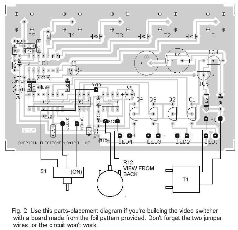
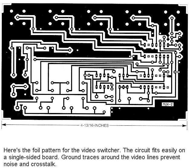
3 connect to the video inputs through J1-J4. The inputs are terminated with 75 ohm resistors R1-R4. The gain of the internal video amplifier is set by a feedback network connected to pin 13 of IC1. That feedback network consists of R5-R8 and C3. The gain is set to 2 in order to compensate for any loss through the 75 ohm terminator resistor, R9. The resulting net gain is 1 at output J5. The binary addressing circuit is built around IC2, a CD4017 decade counter. That chip produces one positive output at a time on each of its ten outputs in sequence for every clock pulse. The first four outputs at pins 3,2,4,and 7 are connected to transistors Q1- Q4. Those transistors drive LED1-LED4 through current limiting resistor R15. The outputs from IC2 (pins 2,4, and 7) are also decoded into binary logic by diodes D1-D4. The binary logic is sent to the address input lines of IC1. The number of cameras connected to the video switcher is set with S1. Each switch in S1 is connected to an output from IC2. If, for example, there are only two cameras connected to the video switcher, S1-a is closed. That connects the third output to IC2 s reset line. When IC2 advances to the third count, that output passes through S1-a to the reset, and IC2 resets to zero, activating the first camera. The sequence would be camera 1, camera 2, then back to camera 1. Closing S1-b or S1-c instead of S1-a will let the video switcher cycle through three or four cameras, respectively. Clock pulses for the counter are generated by IC3, an LMC555 CMOS timer. The pulse rate and pulse width is controlled by C4, R10, R11 and potentiometer R12. By adjusting R12, the output frequency of IC3 can be controlled between 1 Hz and 1/20 Hz. The clock pulses from IC3 are connected to IC2 through S2, a three position toggle switch. Switching S2 to the auto position lets the pulses from IC3 select the next camera at a rate set by R12. When S2 is in its center-off position, no switching takes place, and whatever camera input is selected is passed through to the output. The select position on S2 is a momentary contact. That position raises the clock input of IC2 to 5 volts, which increments the binary count and selects the next camera. When S2 is released, it springs back to its center-off position. The clock input of IC2 is then held at a low-logic level by R13. The MAX454 requires 5 volts while the other ICs require only volts. Power is supplied by AC adapter T1, rectifier diodes D5 and D6, regulators IC4 and IC5, and filter capacitors C6-C9. Construction Because of the high frequency video signals involved, the video switcher should be built on a printed circuit board. The circuit is simple enough to fit onto a single-sided board with only two jumpers needed. A foil pattern is included for etching and drilling your own board. Alternatively, an etched board can be purchased from the source given in the parts list. A feature of that board design is ground traces that run between all of the video signal traces in order to keep induced noise and crosstalk between the signals to a minimum. Weather you etch a board from the foil pattern or purchase one from the source in the parts list, use the parts-placement diagram in fig. 2 for component placement. It is easiest to install and solder the resistors and diodes first. Once those components are in place, scrap component leads can be used for the two jumper wires. Next, install S1 and sockets for IC2 and IC3. Do not use a socket for IC1, the MAX454 multiplexer. When installing J1-J5, hold the connectors tight against the board while soldering the center pin. The assembly can then be placed on a heat-resistant surface and the ground pins soldered. Because of their size and mass, a larger soldering iron might be needed to solder J1-J5. Otherwise the board might be damaged if heat is applied too long. Once the connectors are soldered in place, Q1-Q4, IC4, IC5, and all the capacitors can be installed. The LEDs should be installed next, leaving their leads long so that they
4 can be bent to reach through the front panel of the enclosure. Double-check the orientation of the polarized components, so that they are not installed backwards by accident. Once a component is soldered in place, removing it becomes much more difficult. Solder two 3-inch long wires onto the two terminals of R12 that are clockwise when viewing the potentiometer from the back. Connect those wires to the holes for R12 on the board. Three additional 3-inch long wires are soldered onto the terminals of S2. The center terminal connects to the hole near C5 and R13. The momentary-contact terminal connects to the hole near R14. The remaining terminal connects to the hole near IC3 and R10. Solder IC1 directly onto the circuit board. That will result in the shortest possible lead length for the video signals. Plug IC2 and IC3 into their sockets, being careful to handle them as static-sensitive CMOS devices. Solder the T1 leads onto the board. Examine the board for any wiring errors, bad solder joints, and incorrect components. Once the assembly is inspected, it can be tested. Testing Plug T1 into an AC outlet and measure the voltages across C8 nd C9. The voltage across C8 should measure volts. Across C9, the voltage should be -5 volts. To select two cameras, set S1-a on; to select three cameras, set set S1-b on; and to select all four cameras, set S1-c on. Only one switch at a time should be on. When switch S2 is toggled to its momentary position, the LEDs should sequence to the next indicator each time S2 is toggled. The order of the LEDs should cycle from 1 through 4 and repeat. When S2 is set to automatic, the LEDs should automatically at a rate that should vary as potentiometer R12 is adjusted. Connect cameras to J1-J4 and a monitor to J5. The video signal on the monitor should switch from camera to camera according to the LEDs. After testing is completed, drill appropriate holes in a suitable enclosure for J1-J5, LED1-LED4, S2, and R12. Mount the board in the enclosure using the mounting hardware for J1-J5 to hold it in place. Mount R12 and S2 in the front panel and bend the LEDs so they fit through the holes in the panel. The hole for the T1 wire should be drilled at a point where the two halves of the enclosure meet. Tie a knot in the wire for strain relief and place the wire in the enclosure hole with the knot on the inside of the enclosure before closing the case. That completes the project. If all has gone well, as is likely, your video switcher is now ready for use.
5 PARTS LIST SEMICONDUCTORS IC1 - MAX454 multiplexer, integrated circuit (MAXIM) IC2 - CD4017 decade counter, integrated circuit IC3 - LMC555 timer, integrated circuit IC4-78l05 voltage regulator, integrated circuit IC5-79l05 voltage regulator, integrated circuit Q1-Q4 - MPSA14, NPN transistor D1-D4-1N914, silicon diode D5, D6-1N4004, silicon diode LED1-LED4 - Light emitting diode, red RESISTORS (all resistors are 1/8 watt, 5% units unless otherwise noted) R1-R4, R9-R15-75 ohm R5-150,000 ohm R6-620 ohm R ohm R ohm R10-10,000 ohm R11-51,000 ohm R12 - I megohm potentiometer, panel mount R13, R14-100,000 ohm CAPACITORS C1,C2,C5-0.1 F, 50 WVDC, metalized film C3-6.8 pf, ceramic disc C4-10 F, 50 WVDC, low leakage electrolytic C5, C7-470 F, 25 WVDC, electrolytic C8, C9-100 F, 16 WVDC, electrolytic ADDITIONAL PARTS AND MATERIALS S1 - DIP switch, 3 position S2 - Toggle switch, single pole double throw, one momentary position (Digi-Key CK1028-ND or similar) J1-J5 - Video connector, chassis mount, F type T1-9 volt AC wall adapter transformer PC board, IC sockets, LED holders, 22 gauge hookup wire, knob, enclosure, hardware, etc.
6 IC1 MAX454 C1.1 J1 J2 J3 J4 R1 75 R2 75 R3 75 R IC1 MAX R5 R6 150K 620 C3 6.8 PF R9 75 R7 1.1K R8 1K J5-5 C2.1 R10 10K D1 D2 D3 D4 4 8 R11 7 IC Select MPSA14 51K LMC555 R12 3 S2 14 IC2 CD a b c Q4 Q3 Q2 Q1 1M C Auto R13 100K C R14 100K S1 LED4 LED3 LED2 LED1 R15 75 D6 1N C6 T1 9 VAC 470 IC4 78L05 + C VAC D5 1N4004 IC5 79L05 C9 C Fig. 1 The video switcher is built around a Maxim MAX454 multiplexer chip. Up to four cameras can be viewed on one monitor in sequence.
7
8
Bill of Materials: Super Simple Water Level Control PART NO
 Super Simple Water Level Control PART NO. 2169109 Design a simple water controller in which electrodes are required to sense high and low water levels in a tank. Whenever the water level falls below the
MONO AMPLIFIER KIT ESSENTIAL INFORMATION. Version 2.2 CREATE YOUR OWN SPEAKER DOCK WITH THIS
 ESSENTIAL INFORMATION BUILD INSTRUCTIONS CHECKING YOUR PCB & FAULT-FINDING MECHANICAL DETAILS HOW THE KIT WORKS CREATE YOUR OWN SPEAKER DOCK WITH THIS MONO AMPLIFIER KIT Version 2.2 Build Instructions
Nixie Clock Type Frank 2 Z570M
 Assembly Instructions And User Guide Nixie Clock Type Frank 2 Z570M Software version: 7R PCB Revision: 11 April 09-1 - 1. INTRODUCTION 1.1 About the clock Nixie clock type Frank 2 is a compact design with
16 Stage Bi-Directional LED Sequencer
 16 Stage Bi-Directional LED Sequencer The bi-directional sequencer uses a 4 bit binary up/down counter (CD4516) and two "1 of 8 line decoders" (74HC138 or 74HCT138) to generate the popular "Night Rider"
DIY KIT MHZ 8-DIGIT FREQUENCY METER
 This kit is a stand-alone frequency meter capable of measuring repetitive signals up to a frequency of 50MHz. It has two frequency ranges (15 and 50 MHz) as well as two sampling rates (0.1 and 1 second).
Nixie Clock Type Frank 3
 Assembly Instructions And User Guide Nixie Clock Type Frank 3 Software version: 7R PCB Version: 11 April 09-1 - 1. INTRODUCTION 1.1 About the clock Nixie clock type Frank 3 is a compact design with all
Tube Cricket Build Guide
 Tube Cricket Build Guide The Tube Cricket is a small-wattage amp that puts out about 1 watt of audio power. With a 12AU7 tube-preamp and a JRC386 power amp, the Tube Cricket gives you great tone in a compact
TKEY-K16. Touch CW automatic electronic keyer. (No moving parts no contacts) Assembly manual. Last review: March 15, 2018
 Assembly manual. Last review: March 15, 2018") TKEY-K16 Touch CW automatic electronic keyer (No moving parts no contacts) Assembly manual Last review: March 15, 2018 Commands and use manual of the K16 and Updates and news: www.ea3gcy.com Thanks for
TKEY-K16 Touch CW automatic electronic keyer (No moving parts no contacts) Assembly manual Last review: March 15, 2018 Commands and use manual of the K16 and Updates and news: www.ea3gcy.com Thanks for
EXPERIMENT #6 DIGITAL BASICS
 EXPERIMENT #6 DIGITL SICS Digital electronics is based on the binary number system. Instead of having signals which can vary continuously as in analog circuits, digital signals are characterized by only
Scanned and edited by Michael Holley Nov 28, 2004 Southwest Technical Products Corporation Document Circa 1976
 GT-6144 Graphics Terminal Kit The GT-6144 Graphics Terminal Kit is a low cost graphics display unit designed to display 96 lines of 64 small rectangles per line on a standard video monitor or a slightly
TARGET INTERFACE BOARD COIN DOOR SECTION 6. PARTS LISTING. TABLE 2 Lamp Drivers - 14 Volt Lamps
 TABLE 2 Lamp Drivers - Volt Lamps LAMP DRIVER TURNED DRIVEN BY ON By: Figure 10. Taking voltage measurement on power supply. Dart Round Game1 Game2 Game3 Game4 Bust Remove Darts Throw Darts Game Over Select
DEM 9ULNACK 3.4 GHz. PHEMT LNA amplifier complete kit assembly guide
 DEM 9ULNACK 3.4 GHz. PHEMT LNA amplifier complete kit assembly guide SPECIFICATIONS Noise Figure: < 0.8 db Gain: > 15 db Frequency Range: 3400-3500 MHz Input Voltage: 7-16 VDC Description: The 9ULNACK
INTEGRATED CIRCUITS DATA SHEET. TDA4510 PAL decoder. Product specification File under Integrated Circuits, IC02
 INTEGRATED CIRCUITS DATA SHEET File under Integrated Circuits, IC02 March 1986 GENERAL DESCRIPTION The is a colour decoder for the PAL standard, which is pin sequent compatible with multistandard decoder
Summit Systems Sound Board Modification
 Summit Systems Sound Board Modification The Summit slots fitted with the music feature play two sounds; one when the coin is inserted, and the other that plays as winning coins pass through the hopper
Nixie Clock Kit V1.08 Assembly and Operation
 Nixie Clock Kit V1.08 Assembly and Operation Hardware Revision 14.05.2005 Software Version 6.0 Revision 19.04.2006 This document is copyrighted. No parts of this documentation may be used commercially.
Multi-Key v2.4 Multi-Function Amplifier Keying Interface
 Multi-Key v2.4 Multi-Function Amplifier Keying Interface ASSEMBLY & OPERATION INSTRUCTIONS INTRODUCTION The Harbach Electronics, LLC Multi-Key is a multi-function external device designed for the safe
GEKCO SUBCARRIER REFERENCE OSCILLATOR MODEL SRO10 OPERATION/SERVICE MANUAL
 GEKCO MODEL SRO10 SUBCARRIER REFERENCE OSCILLATOR OPERATION/SERVICE MANUAL GEKCO Labs PO Box 642 Issaquah, WA 98027 (425) 392-0638 P/N 595-431 REV 5/98 Copyright c 1998 GEKCO Labs All Rights Reserved Printed
Nixie Tube Clock Type Marsden
 Assembly Instructions And User Guide Nixie Tube Clock Type Marsden Software version: RTC-1.3 PCB Revision: 16 Aug 10-1 - 1. INTRODUCTION 1.1 About the clock Nixie clock type Marsden is a compact design
RVS-8 Repeater Voting System. Assembly Manual Ver 2.1
 RVS-8 Repeater Voting System Assembly Manual Ver 2. LDG Electronics 445 Parran Road St. Leonard MD 20685 Phone: 40-586-277 Fax: 40-586-8475 e-mail: ldg@radix.net Web site: www://radix.net/~ldg Introduction:
EECS 140 Laboratory Exercise 7 PLD Programming
 1. Objectives EECS 140 Laboratory Exercise 7 PLD Programming A. Become familiar with the capabilities of Programmable Logic Devices (PLDs) B. Implement a simple combinational logic circuit using a PLD.
OPERATING INSTRUCTIONS FOR SYLVANIA. Type I08 Cathode-Ray Oscilloscope. Sylvania Electric Products Inc. Industrial Apparatus. Emporium, Pennsylvania
 OPERATING INSTRUCTIONS FOR SYLVANIA Type I08 Cathode-Ray Oscilloscope Sylvania Electric Products Inc. Industrial Apparatus Plant Emporium, Pennsylvania OPERATING INSTRUCTIONS FOR Sylvania Type 08 Cathode-Ray
ADD AN AUDIO MESSAGE TO YOUR PRODUCT WITH THIS RECORD & PLAYBACK KIT
 ADD AN AUDIO MESSAGE TO YOUR PRODUCT WITH THIS RECORD & PLAYBACK KIT BUILD INSTRUCTIONS Before you start take a look at the Printed Circuit Board (PCB). The components go in the side with the writing on
Assembly Instructions - CT1024 CRT Terminal Introduction
 Assembly Instructions - CT1024 CRT Terminal Introduction The CT1024 unit is designed to store and display two individual pages of 16 lines of 32 characters on a modified television or video monitor. Connections
TECHNOLOGY WILL SAVE US: THE LUMIPHONE
 TECHNOLOGY WILL SAVE US: THE LUMIPHONE This is a step-by-step guide to soldering your own Lumiphone. The equipment you should have at your station: goggles, soldering mat, soldering Iron, solder and side
While the parts are already inventoried at the factory, please verify the inventory check as you go:
 Thank you for purchasing the kit for building the WJ9J DTMF controller. After building, you should read the document on operation (WJ9JDTMFControllerV5.pdf) in order to use. This is also in the link in
Computer Systems Architecture
 Computer Systems Architecture Fundamentals Of Digital Logic 1 Our Goal Understand Fundamentals and basics Concepts How computers work at the lowest level Avoid whenever possible Complexity Implementation
VU-1 VU Meter Kit Volume Unit Meter
 VU-1 VU Meter Kit Volume Unit Meter Simplicity Counts, Detail Matters. No part of this document may be reproduced, either mechanically or electronically, posted online on the Internet, in whole or in part,
Mal-2 assembly guide v1.0
 Mal-2 assembly guide v.0 SONIC POTIONS Schematic and BOM The BOM can be found on Google Docs Prepare the PCB Separate the PCBs using some pliers. PCB We start with the lower PCB and assemble it beginning
EPROM pattern generator with "Genlock"
 EPROM pattern generator with "Genlock" This generator uses an EPROM to store several pictures that can then be selected by means of a thumb-wheel switch. Alternatively, if the pictures stored are in a
MASTR II BASE STATION 12/24V POWER SUPPLY 19A149979P1-120 VOLT/60 Hz 19A149979P2-230 VOLT/50 Hz
 Mobile Communications MASTR II BASE STATION 12/24V POWER SUPPLY 19A149979P1-120 VOLT/60 Hz 19A149979P2-230 VOLT/50 Hz CAUTION THESE SERVICING INSTRUCTIONS ARE FOR USE BY QUALI- FIED PERSONNEL ONLY. TO
Christmas LED Snowflake Project
 Christmas LED Snowflake Project Version 1.1 (01/12/2008) The snowflake is a follow-on from my Christmas star project from a few years ago. This year I decided to make a display using only white LEDs, shaped
LABORATORY # 1 LAB MANUAL. Digital Signals
 Department of Electrical Engineering University of California Riverside Laboratory #1 EE 120 A LABORATORY # 1 LAB MANUAL Digital Signals 2 Objectives Lab 1 contains 3 (three) parts and the objectives are
OPERATION NOTES FOR PSIDEX AUDIO PGP-1A PRE-AMPLIFIER DESCRIPTION INSTALLATION
 OPERATION NOTES FOR PSIDEX AUDIO PGP-1A PRE-AMPLIFIER DESCRIPTION The Psidex Audio Laboratory PGP- 1A is a vacuum tube based microphone preamp and program line amplifier designed to provide solid, robust
EA350. Generator Automatic Voltage Regulator Operation Manual
 Generator Automatic Voltage Regulator Operation Manual Self Excited Automatic Voltage Regulator For General Generators Compatible with Marathon SE350* * Use for reference purpose only and not a genuine
[ Photos ] [ Wares ] [ Library ] [ Dave's Web ] [ Matt's Web ] Wares [ SWISH ] [ Simple Search ] [ Trunk Calc ]
![[ Photos ] [ Wares ] [ Library ] [ Dave's Web ] [ Matt's Web ] Wares [ SWISH ] [ Simple Search ] [ Trunk Calc ]](/thumbs/85/91698811.jpg "[ Photos ] [ Wares ] [ Library ] [ Dave's Web ] [ Matt's Web ] Wares [ SWISH ] [ Simple Search ] [ Trunk Calc ]") [ Photos ] [ Wares ] [ Library ] [ Dave's Web ] [ Matt's Web ] Wares [ SWISH ] [ Simple Search ] [ Trunk Calc ] Realistic PRO-2006 Hardware Modifications Note Edited on January 1st, 1970, 00:00 UT. Improper
[ Photos ] [ Wares ] [ Library ] [ Dave's Web ] [ Matt's Web ] Wares [ SWISH ] [ Simple Search ] [ Trunk Calc ] Realistic PRO-2006 Hardware Modifications Note Edited on January 1st, 1970, 00:00 UT. Improper
LAB #6 State Machine, Decoder, Buffer/Driver and Seven Segment Display
 LAB #6 State Machine, Decoder, Buffer/Driver and Seven Segment Display LAB OBJECTIVES 1. Design a more complex state machine 2. Design a larger combination logic solution on a PLD 3. Integrate two designs
Documentation VFD clock 8 a clock
 Documentation VFD clock 8 a clock This documentation is protected by our copyright. It must not be used for commercial purposes. Congratulations on your purchase of your VFD clock. To guarantee success
Physics 123 Hints and Tips
 Physics 123 Hints and Tips Solderless Breadboards All of the analog labs and most of the digital labs will be built on the Proto-Board solderless breadboards. These provide three solderless breadboard
7 SEGMENT LED DISPLAY KIT
 ESSENTIAL INFORMATION BUILD INSTRUCTIONS CHECKING YOUR PCB & FAULT-FINDING MECHANICAL DETAILS HOW THE KIT WORKS CREATE YOUR OWN SCORE BOARD WITH THIS 7 SEGMENT LED DISPLAY KIT Version 2.0 Which pages of
MAKE AN RGB CONTROL KNOB.
 MAKE AN RGB CONTROL KNOB. This is a knob based colour changing controller that uses a custom programmed microcontroller to pack a lot of features into a small affordable kit. The module can drive up to
Constructing and Operating: The Island Keyer
 Constructing and Operating: The Island Keyer Construction: General notes about building: The components should be inserted a few at a time, soldered in place and then the leads are clipped. Note that all
A MISSILE INSTRUMENTATION ENCODER
 A MISSILE INSTRUMENTATION ENCODER Item Type text; Proceedings Authors CONN, RAYMOND; BREEDLOVE, PHILLIP Publisher International Foundation for Telemetering Journal International Telemetering Conference
Self Excited Automatic Voltage Regulator For Generator Compatible with Marathon SE350* Operation Manual
 Self Excited Automatic Voltage Regulator For Generator Compatible with Marathon SE350* Operation Manual s * Use for reference purpose only and not a genuine Marathon product. 1. INTRODUCTION Sensing Input
Nixie Clock Type Quattro'
 Assembly Instructions And User Guide Nixie Clock Type Quattro' - 1 - Issue Number Date REVISION HISTORY 2 8 Sept 2012 Errors corrected 1 27 July 2012 New document Reason for Issue - 2 - 1.1 Nixie Quattro
Obtained from Omarshauntedtrail.com
 http://www.cindybob.com/halloween/ledlighting/ledspotlights/ Introduction In our 2005 haunt providing 120V AC power to the various lights and props requiring it became a fairly large problem. Extension
Color Organ Triple Deluxe II.
 http://wwwinstructablescom/id/color-organ-triple-deluxe-ii/ Food Living Outside Play Technology Workshop Color Organ Triple Deluxe II by ledartist on January 13, 2013 Table of Contents Color Organ Triple
"shell" digital storage oscilloscope (Beta)
") "shell" digital storage oscilloscope (Beta) 1. Main board: solder the element as the picture shows: 2. 1) Check the main board is normal or not Supply 9V power supply through the connector J7 (Note: The
"shell" digital storage oscilloscope (Beta) 1. Main board: solder the element as the picture shows: 2. 1) Check the main board is normal or not Supply 9V power supply through the connector J7 (Note: The
Assembly and Operating Instructions for HiViz.com Kits
 information and inspiration for students, teachers and hobbyists About Tools Products Activities Galleries Projects FAQ Links Contact Assembly and Operating Instructions for HiViz.com Kits For best results
Total solder points: 123 Difficulty level: beginner 1. advanced AUDIO ANALYZER K8098. audio gea Give your. . high-tech ILLUSTRATED ASSEMBLY MANUAL
 Total solder points: 123 Difficulty level: beginner 1 2 3 4 5 advanced AUDIO ANALYZER K8098 ra audio gea Give your. look high-tech ILLUSTRATED ASSEMBLY MANUAL H8098IP-1 Features & Specifications Features
EA63-7D. Generator Automatic Voltage Regulator Operation Manual. Self Excited Automatic Voltage Regulator
 EA63-7D Generator Automatic Voltage Regulator Operation Manual Self Excited Automatic Voltage Regulator SP POWERWORLD LTD Willows, Waterside, Ryhall, Stamford, Lincs, PE9 4EY, UK Tel: +44 1780 756872 -
Laboratory 8. Digital Circuits - Counter and LED Display
 Laboratory 8 Digital Circuits - Counter and Display Required Components: 2 1k resistors 1 10M resistor 3 0.1 F capacitor 1 555 timer 1 7490 decade counter 1 7447 BCD to decoder 1 MAN 6910 or LTD-482EC
ASSEMBLING. the. ECEbot. Printed Circuit Board: Part Three. Due Date. The Part Three assembly steps must be completed prior to:
 ASSEMBLING the ECEbot Printed Circuit Board: Part Three Due Date The Part Three assembly steps must be completed prior to: Prepared by R.C. Maher September 2008 Copyright 2008 Department of Electrical
N3ZI Digital Dial Manual For kit with Backlit LCD Rev 4.00 Jan 2013 PCB
 N3ZI Digital Dial Manual For kit with Backlit LCD Rev 4.00 Jan 2013 PCB Kit Components Item Qty Designator Part Color/Marking PCB 1 LCD Display 1 LCD 1602 Volt Regulator 1 U1 78L05, Black TO-92 Prescaler
Monday 28 January 2013 Morning
 Monday 28 January 2013 Morning GCSE DESIGN AND TECHNOLOGY Electronics and Control Systems A514/01 Technical Aspects of Designing and Making: Electronics *A528620113* Candidates answer on the Question Paper.
SPECIAL SPECIFICATION 6911 Fiber Optic Video Data Transmission Equipment
 2004 Specifications CSJ 3256-02-079 & 3256-03-082 SPECIAL SPECIFICATION 6911 Fiber Optic Video Data Transmission Equipment 1. Description. Furnish and install Fiber Optic Video Data Transmission Equipment
N3ZI Digital Dial Manual For kit with Serial LCD Rev 3.04 Aug 2012
 N3ZI Digital Dial Manual For kit with Serial LCD Rev 3.04 Aug 2012 Kit properly assembled and configured for Standard Serial LCD (LCD Not yet connected) Kit Components Item Qty Designator Part Color/Marking
Telemetry Receiver Installation Guide
 BBV Telemetry Receiver Installation Guide Models covered Rx200 Building Block Video Ltd., Unit 1, Avocet Way, Diplocks Industrial Estate, Hailsham, East Sussex, UK. Tel: +44 (0)1323 842727 Fax: +44 (0)1323
Introduction 1. Green status LED, controlled by output signal ST. Sounder, controlled by output signal Q6. Push switch on input D6
 Introduction 1 Welcome to the GENIE microcontroller system! The activity kit allows you to experiment with a wide variety of inputs and outputs... so why not try reading sensors, controlling lights or
QUIZ BUZZER KIT TEACHING RESOURCES. Version 2.0 WHO ANSWERED FIRST? FIND OUT WITH THIS
 TEACHING RESOURCES SCHEMES OF WORK DEVELOPING A SPECIFICATION COMPONENT FACTSHEETS HOW TO SOLDER GUIDE WHO ANSWERED FIRST? FIND OUT WITH THIS QUIZ BUZZER KIT Version 2.0 Index of Sheets TEACHING RESOURCES
Model 1421 Distribution Amplifier
 Model 1421 Distribution Amplifier Installation and Operating Instructions The 1421 Distribution Amplifier provides four independent, wide bandwidth outputs from one video input. The unit is color compatible
J R Sky, Inc. tel: fax:
 STEREO OPTICAL RECORDING SYSTEM N UOPTIX STEREO OPTICAL RECORDING MONITOR LEFT SYSTEM MODE PREVIEW RECORD BIAS RECORD REV SETUP TEST RIGHT INPUT SETUP INPUT BIAS SETUP BIAS INPUT STEREO AUX MONO DIRECT
PC BOARD MOUNT DISPLAYS
 PC BOARD MOUNT DISPLAYS The Trusted Source for Innovative Control Solutions 1-717-767-6511 891 QUICK Specs Counters LCD DISPLAY SUB-CUB 1 & 2 SUB-CUB 2-8A SUB-CUB D SUB-CUB T Description Count Indication
 I R T Electronics Pty Ltd A.B.N. 35 000 832 575 26 Hotham Parade, ARTARMON N.S.W. 2064 AUSTRALIA National: Phone: (02) 9439 3744 Fax: (02) 9439 7439 International: +61 2 9439 3744 +61 2 9439 7439 Email:
Manual Version Audio/Video Switchers. AV4x1P AV8x1P AV8x1A
 AV4x1P AV8x1P AV8x1A Audio/Video Switchers Manual Version 2.01 BURST ELECTRONICS INC ALBUQUERQUE, NM 87109 USA (505) 898-1455 VOICE (505) 890-8926 TECH SUPPORT Made in USA (505) 898-0159 FAX www.burstelectronics.com
COHERENCE ONE PREAMPLIFIER
 COHERENCE ONE PREAMPLIFIER OWNER S MANUAL TABLE OF CONTENTS Introduction Features Unpacking Instructions Installation Phono Cartridge Loading Basic Troubleshooting Technical Specifications Introduction
COLOUR CHANGING USB LAMP KIT
 TEACHING RESOURCES SCHEMES OF WORK DEVELOPING A SPECIFICATION COMPONENT FACTSHEETS HOW TO SOLDER GUIDE SEE AMAZING LIGHTING EFFECTS WITH THIS COLOUR CHANGING USB LAMP KIT Version 2.1 Index of Sheets TEACHING
Reaction Game Kit MitchElectronics 2019
 Reaction Game Kit MitchElectronics 2019 www.mitchelectronics.co.uk CONTENTS Schematic 3 How It Works 4 Materials 6 Construction 8 Important Information 9 Page 2 SCHEMATIC Page 3 SCHEMATIC EXPLANATION The
Nutube.US. 6P1 Evaluation Board. User Manual
 Nutube.US 6P1 Evaluation Board User Manual Introduction The 6P1 Evaluation Board (EVB) is a vehicle for testing and evaluating the Korg Nutube 6P1 dual triode in audio circuits. This product is designed
INPUT OUTPUT GAIN DELAY. Hue Candela Strobe Controller. Hue Candela s STROBE CONTROLLER. Front Panel Actual Size 7 ¼ By 4 ¾ POWER. msec SEC 10 1.
 Hue Candela s STROBE CONTROLLER INPUT OUTPUT ON TIME POWER NO B C A GAIN X LOCK Y OUT Z Hue Candela Strobe Controller 4 5 6 7..... 8. 3. 9. 2 10.. 1 11. STEP m.. 0 10 1. 10 10 1.0 10 zero DELAY. 03. 02.
PHYS 3322 Modern Laboratory Methods I Digital Devices
 PHYS 3322 Modern Laboratory Methods I Digital Devices Purpose This experiment will introduce you to the basic operating principles of digital electronic devices. Background These circuits are called digital
VU Meter Buffer DIY Kit
 VU Meter Buffer DIY Kit Warning This document is distributed for educational purposes only. This equipment operates at potentially lethal voltages. Only trained, qualified personnel should operate, maintain,
Assembly Instructions And User Guide. Nixie FunKlock. FunKlock Issue 4 (1 February 2017)
") Assembly Instructions And User Guide Nixie FunKlock - 1 - Issue Number Date REVISION HISTORY 4 1 February 2017 New diode for D2 3 27 December 2013 C7 / C8 error page 15 2 7 November 2013 Errors corrected
Assembly Instructions And User Guide Nixie FunKlock - 1 - Issue Number Date REVISION HISTORY 4 1 February 2017 New diode for D2 3 27 December 2013 C7 / C8 error page 15 2 7 November 2013 Errors corrected
4.9 BEAM BLANKING AND PULSING OPTIONS
 4.9 BEAM BLANKING AND PULSING OPTIONS Beam Blanker BNC DESCRIPTION OF BLANKER CONTROLS Beam Blanker assembly Electron Gun Controls Blanker BNC: An input BNC on one of the 1⅓ CF flanges on the Flange Multiplexer
MSCI 222C Class Readings Schedule. MSCI 222C - Electronics 11/27/18. Copyright 2018 C.P.Rubenstein Class Seating Chart Mondays
 222-01 Class Seating Chart Mondays Electronics Door MSCI 222C Fall 2018 Introduction to Electronics Charles Rubenstein, Ph. D. Professor of Engineering & Information Science Session 11: Mon/Tues 11/19/18
Simple Way To Brighten Up A 17 Computer Monitor Picture Tube
 Simple Way To Brighten Up A 17 Computer Monitor Picture Tube By Jestine Yong http://www.electronicrepairguide.com Give a copy to a friend This article is free. You can post this article to your website.
ELECTRICAL ENGINEERING DEPARTMENT California Polytechnic State University
 EECTRICA ENGINEERING DEPARTMENT California Polytechnic State University EE 361 NAND ogic Gate, RS Flip-Flop & JK Flip-Flop Pre-lab 7 1. Draw the logic symbol and construct the truth table for a NAND gate.
MSCI 222C Fall 2018 Introduction to Electronics
 MSCI 222C Fall 2018 Introduction to Electronics Charles Rubenstein, Ph. D. Professor of Engineering & Information Science Session 11: Mon/Tues 11/19/18 & 11/20/18 (H10,Q9,L9) Mondays 1:00-3:50pm; Tuesdays
STD-525T PRECISION TIMER
 FN:STD525TM1.DOC STD-525T PRECISION TIMER DESCRIPTION The STD-525T Precision Timer measures and displays accurate elapsed time in minutes, seconds, tenths of seconds, and hundredths of seconds (MM.SS.TH)
NORTHWESTERN UNIVERSITY TECHNOLOGICAL INSTITUTE
 NORTHWESTERN UNIVERSITY TECHNOLOGICL INSTITUTE ECE 270 Experiment #8 DIGITL CIRCUITS Prelab 1. Draw the truth table for the S-R Flip-Flop as shown in the textbook. Draw the truth table for Figure 7. 2.
Synchronization circuit with synchronized vertical divider system for 60 Hz TDA2579C
 FEATURES Synchronization and horizontal part Horizontal sync separator and noise inverter Horizontal oscillator Horizontal output stage Horizontal phase detector (sync to oscillator) Triple current source
University of Illinois at Urbana-Champaign
 University of Illinois at Urbana-Champaign Digital Electronics Laboratory Physics Department Physics 40 Laboratory Experiment 3: CMOS Digital Logic. Introduction The purpose of this lab is to continue
Westrex RA1713B Auxiliary Record Electronics
 Westrex RA1713B Auxiliary Record Electronics INTRODUCTION The RA-1713B is an auxiliary electronics system for use with the Westrex RA- 1712B. It comprises a current regulated, digital readout, recorder
Digital Effects Pedal Description Ross Jongeward 10 December 2014
 Digital Effects Pedal Description Ross Jongeward 10 December 2014 1 Contents Section Number Title Page 1.1 Introduction..3 2.1 Project Electrical Specifications..3 2.1.1 Project Specifications...3 2.2.1
Bill of Materials: Magic Color PART NO
 Magic Color PART NO. 2193838 Magic color is a guessing game. With this game you can surprise your friends and leave them with amazement, how the game guesses what they have in their minds. Only two selections
DIN Connectors DIN06 E-03
 DIN Connectors DIN0 E-0 Contents Introduction HOSIDEN DIN connectors are supplied to electronic equipment manufacturers both in Japan and overseas and are very well accepted because of high quality, a
Laboratory 11. Required Components: Objectives. Introduction. Digital Displays and Logic (modified from lab text by Alciatore)
") Laboratory 11 Digital Displays and Logic (modified from lab text by Alciatore) Required Components: 2x lk resistors 1x 10M resistor 3x 0.1 F capacitor 1x 555 timer 1x 7490 decade counter 1x 7447 BCD to
Laboratory 11 Digital Displays and Logic (modified from lab text by Alciatore) Required Components: 2x lk resistors 1x 10M resistor 3x 0.1 F capacitor 1x 555 timer 1x 7490 decade counter 1x 7447 BCD to
The NorCal SMT Dummy Load Assembly and Operating Manual Rev. 1.0 January 4, 2005
 The NorCal SMT Dummy Load Assembly and Operating Manual Rev. 1.0 January 4, 2005 Copyright 2005 W3CD 1 1. Introduction The NorCal SMT Dummy Load is a practice kit for anyone wishing to gain some experience
VGA to PAL and NTSC converter
 VGA to PAL and NTSC converter Design and copyright by Tomi Engdahl 1996,1999 NOTE: There are few mistakes on the dawings shown on this page. I have recieved lots of questions related to them and I don't
Low Noise Solid State Phono Preamplifier User's Guide and Operating Information
 Bel Canto Design PHONO 1 Low Noise Solid State Phono Preamplifier User's Guide and Operating Information Bel Canto Design 212 Third Avenue North Suite 345 Minneapolis, MN 55401 Phone: (612) 317.4550 Fax:
AD9884A Evaluation Kit Documentation
 a (centimeters) AD9884A Evaluation Kit Documentation Includes Documentation for: - AD9884A Evaluation Board - SXGA Panel Driver Board Rev 0 1/4/2000 Evaluation Board Documentation For the AD9884A Purpose
ECB DIGITAL ELECTRONICS PROJECT BASED LEARNING PROJECT REPORT ON 7 SEGMENT DIGITAL STOP WATCH USING DECODER
 ECB2212 - DIGITAL ELECTRONICS PROJECT BASED LEARNING PROJECT REPORT ON 7 SEGMENT DIGITAL STOP WATCH USING DECODER SUBMITTED BY ASHRAF HUSSAIN (160051601105) S SAMIULLAH (160051601059) CONTENTS >AIM >INTRODUCTION
SPECIAL SPECIFICATION 1291 Fiber Optic Video Data Transmission Equipment
 1993 Specifications CSJ 0500-01-117 SPECIAL SPECIFICATION 1291 Fiber Optic Video Data Transmission Equipment 1. Description. This Item shall govern for the furnishing and installation of Fiber Optic Video
DDS VFO CONSTRUCTION MANUAL. DDS VFO Construction Manual Issue 1.1 Page 1
 DDS VFO CONSTRUCTION MANUAL DDS VFO Construction Manual Issue 1.1 Page 1 Important Please read before starting assembly STATIC PRECAUTION The DDS VFO kit contains the following components which can be
UNIT V 8051 Microcontroller based Systems Design
 UNIT V 8051 Microcontroller based Systems Design INTERFACING TO ALPHANUMERIC DISPLAYS Many microprocessor-controlled instruments and machines need to display letters of the alphabet and numbers. Light
Frequency counter / Digital Dial
 Frequency counter / Digital Dial The Digital Dial is primarily intended to be used as a simple means of adding a digital frequency read out to single band QRP radios. A programmable IF offset feature allows
ROUGH DRAFT. Guide. Installation. Signal Booster. Wilson. AG Pro 75 Smart Technology In-Building Wireless 800/1900 Signal Booster.
 Signal Booster Installation Guide Contents: AG Pro 75 Smart Technology In-Building Wireless 800/1900 Signal Booster Before Getting Started.... 1 Antenna Options & Accessories.................... 1 Easy
INTRODUCTION (EE2499_Introduction.doc revised 1/1/18)
") INTRODUCTION (EE2499_Introduction.doc revised 1/1/18) A. PARTS AND TOOLS: This lab involves designing, building, and testing circuits using design concepts from the Digital Logic course EE-2440. A locker
INTRODUCTION (EE2499_Introduction.doc revised 1/1/18) A. PARTS AND TOOLS: This lab involves designing, building, and testing circuits using design concepts from the Digital Logic course EE-2440. A locker
Revision 1.2d
 Specifications subject to change without notice 0 of 16 Universal Encoder Checker Universal Encoder Checker...1 Description...2 Components...2 Encoder Checker and Adapter Connections...2 Warning: High
Cryoelectronics. MS-FLL User s Manual. Mr. SQUID Flux-Locked Loop. STAR Cryoelectronics 25 Bisbee Court, Suite A Santa Fe, NM U. S. A.
 Cryoelectronics MS-FLL User s Manual Mr. SQUID Flux-Locked Loop STAR Cryoelectronics 25 Bisbee Court, Suite A Santa Fe, NM 87508 U. S. A. STAR Cryoelectronics, LLC ii Table of Contents Revision Record...
Dust Sensor using GP Y
 Dust Sensor using GP Y Dust sensors detect fine dust ( aerosol ) floating in the air. They are used to determine air quality indoor and outdoor. Limits of the GP2Y10 The GP2Y10 sensor was developed to