AUDIO VIDEO SYSTEMS
|
|
|
- Aldous Eustace Newman
- 5 years ago
- Views:
Transcription
1 AUDIO VIDEO SYSTEMS PROF. PRATIKGIRI GOSWAMI ASSISTANT PROFESSOR ELECTRONICS & COMMUNICATION DEPARTMENT, L. D. COLLEGE OF ENGINEERING
2 QUANTIZATION & ENCODING
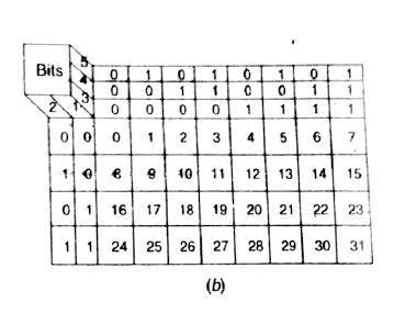
3 QUANTIZATION & ENCODING Assume that sampling its amplitude at 32 levels Period of wave shape is one second sampling at 100 ms intervals 10 samples available during each cycle. Five bit code 32 levels bit sequence as shown in figure for example, 19 is represented with bit A/D converter Clock pulses sampling rate Nyquist criterion 625/50 TV Bandwidth 5 MHz sampling rate must be 10 MHz or faster PAL System sampling rate = 3 x f sc bit rate of 200 Mbits/sec
4 QUANTIZATION & ENCODING 256 level sampling 8 bit code Black level 64 th level with code Peak White level 204 with code
5 QUANTIZATION & ENCODING Audio Quantization: sampling level can range from 64 to 128 depending on the desired sound output quality. CDs 128 sampling levels 7 bits Encoder :
6 DIGITAL SATELLITE TV Because of merits of processing signals in digital form, digital satellite transmission and reception is now common. However, signal distribution to subscribers is mostly through cable networks in analog form. Four Stages : 1. Signal Encoding 2. Processing 3. Modulation 4. Transmission
7 UP-LINK
8 SIGNAL PROCESSING Three Stages : 1. Compression 2. Encryption 3. Packetising Compression : data rate required to transmit digital information is around 200 Mbps and needs channel bandwidth of 50 MHz with provisions for very expensive processing equipments. compression techniques reduce data rate to about 3 to 6 Mbps compression algorithms done in previous chapter motion prediction MPEG etc. Audio Compression eliminating soft sounds that are near louds because their absence at Rx would not matter much on account of limitations of human ear compressed audio data rate can vary from 50 kbps for mono to near 300 kbps for stereo sounds.
9 SIGNAL PROCESSING Encryption : to prevent unauthorized reception of channels for which a special fee is to be paid encrypted before up-linking, by inserting keys keys for decryption are also transmitted with channel data to enable authorized customers to restore normal reproduction of signals. done by inserting a card called SMART CARD in decoder
10 SIGNAL PROCESSING Data Packets : besides audio and video signals, conditional information is also transmitted to the customer which includes access data, PC compatible data and program guide. combined in form of packet which also contains signals to register identity of each packet thus enabling their separation at receiving end. all the packets are time multiplexed into serial data before further processing at transmitting site.
11 RECEPTION AND DECODING
12 DIRECT-TO-HOME SATELLITE TV enables viewers to receive many channels of high quality TV programs via high powered Ku-Band satellites. no distribution cables but the Rx connects through MODEM to the customers telephone line for communication with the subscription service computer for billing purpose. differs in terms of compression from digital satellite TV economics point of view data should be compressed till significant artifacts appear. movies vs basket ball game Ku-band freq are preferred as these are not prone to interference from ground point-to-point communication and also need much smaller diameter dish antenna.
13 DIRECT-TO-HOME SATELLITE TV ku-band 11.7 to GHz high powered 12.2 to 12.7 GHz for efficient operation of DTH Transmission requires dish antennas of diameter between 50 to 90 cm depending on the location of receiving site DTH Rx Front Panel

14 DIRECT-TO-HOME SATELLITE TV TV/DTH or TV/DSB : switches between the satellite signal IN and the terrestrial antenna or cable network IN as desired on turning ON the receiving.
15 DIRECT-TO-HOME SATELLITE TV Out to with modulation on Channel 3 or 4 S video which connects Super Video to the compatible TV set or VCR Wide Band for use in conjunction with future technology such as HDTV and Interactive TV.
16 DIGITAL TV Rx
17 DIGITAL TV Rx RF signal from antenna is demodulated and amplified in tuner in the conventional way to obtain IF output. Demodulated signal is digitized and presented to DSP circuits with the aid of micro-computer. clock freq for the digital circuits is derived from the color subcarrrier burst video signal digitized with 256 levels audio digitized at around 32 KHz in 14 bit resolution
18 DIGITAL TV Rx CCU Central Control Unit Heart micro computer based device which controls and coordinates all the circuits and signal processing functions and provides a user interface. Enables a total flexibility to the user who can control receiver functions, display teletext, obtain multiple picture-in-picture displays for simultaneous viewing of different programs and zooming of the picture. Video Codec : converts analog composite video signal by high speed flash A/D converter into 8 bit digital signal
19 DIGITAL TV Rx Video Processor : separates into two channels luminance and chrominance luminance multiplier brightness, contrast in accordance with the user s choice chrominance encodes relative weightage of R, G and B in electron guns consists of a bandpass filter, an automatic color circuit, a comb filter and color decoder. two streams of signals are then sent back to the video codec which also contains D/A converters to obtain outputs in analog form. Then delay line technique is employed for averaging and later demodulation to obtain U and V outputs which are suitably combined to obtain R-Y, B-Y and G-Y
20 DIGITAL TV Rx Deflection Processing Unit : senses the standard TV signal and synchronizes the vertical and horizontal sweep generators by counting the color subcarrier and locking to it. Audio Codec : samples input signal to produce 1 bit data stream and then converts into 16 bit resolution stream at 35 KHz. The digital identification filter takes out the identification signal and tells whether the broadcast is mono, stereo or bilingual.
21 MERITS OF DIGITAL TV Rx Reduced Ghosts : due to better synchronization Reduction of 50 Hz Flicker : faster rescanning of each picture High Resolution Pictures : picture storage capacity is higher in digital possible to scan second set of lines in-between then usual scan lines thus enabling high resolution picture with the same low resolution incoming signal. Picture-in-Picture (PIP) : to see two programs at the same time Slow Motion Action : each frame can be scanned onto screen several times to freeze the frame Easy adoption to additional displays
22 MERITS OF DIGITAL TV Rx Reduced Operational Instability : effect of component aging on alignment etc and consequent instability encountered in analog receivers is eliminated self tuning and easy routine adjustments
23 DIGITAL TERRESTRIAL TV digital technology and fabrication of VLSI chips digital TV transmission by terrestrial means two decades back despite the fact that digital transmission needs more BW which is too large for a ground based broadcast system. transition from analog to digital terrestrial is slow because of replacement cost of existing equipments at the studios and transmitters. at the receiving end millions of analog Rx in use would need to be discarded or at least provided with converter Another reason for DTT not receiving much attention Satellite TV changing from analog to digital high gain dish antenna to receive broadcasts distribution to subscribers via cables degradation of quality solution DTH major limitation on number of channels available to subscriber
24 STEREO SOUND SYSTEMS Besides loudness, to enable perception of both direction and depth of sound necessary to have two completely separate channels at the Tx and independent detection and amplifying paths in the Rx. Stereo Sound Principle : obtained by placing two mic in front of the stage as shown in figure
25 STEREO SOUND SYSTEMS different lengths of sound path lines time delay in both microphones sound pattern picked up by each mic is fed to its own recording and reproduction channel listener sitting in the centre between two loudspeakers then listens the difference between two sound patterns. FM-FM Stereo
26 STEREO SOUND SYSTEMS FM-FM stereo multiplex where only one FM Tx is used to broadcast both the channel audio signals. pilot signal carrier to synchronize detection in the Rx. at Rx separate L+R and L-R components in their original form (L+R)+(L-R) = 2L and (L+R) (L-R) = 2R Stereo sound in Television accommodated in a different way as devised by PHILIPS IF spectrum consists of vision carrier, first sound carrier at 5.5 MHz and a second sound IF at MHz from vision carrier. both sound carriers are separated by 15.5 x f H to minimize interference.
27 STEREO SOUND SYSTEMS The first sound IF is freq modulated with (L+R) so that mono TV Rx can still reproduce mono sound second IF is FM modulated with 2R information To identify whether transmitted signal is mono or stereo, second IF carrier also carries an identification signal which is KHz pilot carrier amplitude modulated with Hz for stereo or Hz for dual transmission. Stereo information 2(L+R)-2R=2L
28 STEREO SOUND SYSTEMS
29 PROJECTION SYSTEMS CRT Projection on large screen brightness and clarity problems to overcome, new technology called Micro Electro-Mechanical (MEMS) was developed in which, chips like Digital Micromirror Devices (DMD) are used to develop the picture FRONT and REAR display type are now used in Home Entertainemnt Theatres with installation of Dolby Sound System. Direct View Projection System : conventional TV picture tube uses three electron beams and separate phosphors for for R, G, B one looks directly at the surface that TV uses to create the composite picture Rear Projection System : three different CRTs on splitting the video signal produce R, G, B their combined effect can produce the entire visual spectrum for this, CRTs project onto a mirror which bounces the full color image on a fairly large screen located in the upper half of TV box.
30 PROJECTION SYSTEMS Front Projection System : projection and screen are two separate units where the projector projects images onto the front of screen just like theatres Both REAR and FRONT projection configurations use tiny devices like small CRT tube or LCD panels for creating pictures. These devices are called REFLECTIVE meaning that the source incident light picks up to picture by reflecting i.e. bouncing off the device. Some other devices TRANSMITTIVE meaning that the incident light picks up picture by travelling through device which is then magnified by lenses before projections onto the screen.
31 TRANSMITTIVE TYPE CRT Transmittive Projectors : smaller around 9 CRTs are used which emit very bright light lens is put in front of CRT which magnifies image and projects Three configurations One color CRT : color image formed on its screen is magnified with one lens and projected on screen One B&W CRT with color filters : fast rotating color filter wheel with R,G, B segments placed between CRT and projection lens results in rapidly changing three color images forms single colored image due to high speed of wheel and ability of our eyes to integrate them. Three CRTs : one for each primary color three lenses Aligned such that a single colored image appears on the screen
32 TRANSMITTIVE TYPE LCD Transmittive Projectors : to make projectors light and to increase the resolution uses bright light to illuminate the LCD panel image formed is projected by lens system on the screen Transmittive Projectors gradually replaced by reflective type
33 REFLECTIVE TYPE image is formed on a small reflective chip when light shines on the chip, image is reflected off it and through a projection lens gets focused on the screen. MEMS : Two main MEMS systems : DMD and GLV (Grating Light Value) These have a moveable or deformable reflective surface on top of semiconductor chip. Chip generates voltages in response to digital information. These voltage changes the reflective surface rapidly in a controlled way to produce the image that was encoded by the digital information. Projected light bounces off the reflective surface and gets collected by the projector lens.
34 DMD also called digital light processing (DLP), developed by Texas Instruments, USA is small chip that has anywhere up to multi-million tiny mirrors on it depending on the size of the array. Each mirror consists of three physical layers and two air gap layers. The air gap layers separate three physical layers and allow the mirror to tilt +10 or -10 degree. When a voltage is applied to either of the address electrodes, the mirrors tilt representing ON or OFF in a digital signal. Projector light shines on DMD. Light hitting ON mirror will reflect through the projection lens to the screen. ON mirrors will produce bright area on the screen and OFF mirrors dark area. Each mirror is individually controlled. Combination of all mirrors produces monochrome picture on screen. To add colors, 3 color wheel is used.
35 GLV licensed by Sony consists of tiny reflective ribbons mounted over a silicon chip. Ribbons are suspended over a chip with small air gap in between. When voltage is applied below ribbon, ribbon moves towards the chip by a fraction of wavelength of illuminating light. the deformed ribbons form a diffraction grating and various orders of such a light can be combined to form the pixels of an image. The shape of ribbons and therefore image formation can be changed in as little as 20 billions of a second.
36 PROJECTION TELEVISION obtaining large picture from a relatively small picture tube for many applications such as lecture class and medical demonstrations. It is not possible to produce a picture tube with screen area exceeding 40 diagonal due tohigh cost and technological difficulties. simplest projection TV is one in which picture obtained on the screen of a picture tube is enlarged by lens system and projection on a large screen. brightness is low and necessary to darken the room improved version produces much brighter R, G and B with special tubes two piece system positions are fixed for optimum image reproduction Matsushita Electric Co. of Japan produced a complete and compact projection TV system

37 PROJECTION TELEVISION light from the projector is reflected by a mirror on the screen which is assembled along in the same unit. screen size is nearly 150 cm square grown over the years
38 FLAT PANEL DISPLAY conventional picture tube is replaced by flat panel display led to development of LCD and active matrix displays LCDs : simple dot matrix approach Active Matrix Displays : Matsushita produced initially a colour displays with 10 diagonal technology known as matrix drive and deflection in fact an array of 3000 very small electron tubes with an effective resolution of 270 scanning lines display panel measures 370 x 355 x 99 mm made up of lattice electrodes approximately 0.1 mm thick layered between insulating boards.
39 FLAT PANEL DISPLAY
40 FLAT PANEL DISPLAY has 15 very fine wire cathodes and 200 electron beam control electrodes set 200 across and 150 high, deflected in six stages. with the interlaced included, total deflection stage is 32 with output of 1,92,000 pixels in a 400 x 480 matrix. LCD : screen consists of a liquid crystal solution put-in between two glass plates on application of current acts like a shutter to allow more or less light to pass through depending on the intensity of applied charge that is proportional to the applied signal PLASMA : special solution is coated on the inner side of two glass plates has millions of phosphor coated gas bubbles containing plasma application of current triggers phosphors to emit light which in turn combine to create pictures on screen
41 PLASMA PANELS For years, the most common display technology has been the cathode ray tube or CRT. In the last few years, around 115 million new CRT computer monitors and 130 million new television sets based on CRT technology have been sold annually throughout the world. CRTs have been produced in large volumes for over 50 years and consequently, manufacturers have developed very efficient processes and enjoy great economies of scale. This means that CRT technology delivers a good performance at relatively low cost.
42 PLASMA PANELS But now there are newer, slimmer, lighter and more versatile products that are true alternatives to the traditional CRT device. Currently, the most popular technologies are: Plasma display panel, PDP. Liquid crystal display, LCD. Digital light processing, DLP. There are other technologies that are being developed such as organic light-emitting diodes (OLED), field emissive displays and surface conduction electron-emitter displays (SED). The CRT is a well tried and tested technology and remains the standard for standard definition picture quality. Nonetheless, flat panel displays (FPDs) have a number of advantages that makes them more desirable than the CRT.
43 PLASMA PANELS These advantages are: Fully flat display. Large screen formats. Thin (40 mm) suitable for wall hanging. Small in size occupying less desk space. Fully digital internal operation. Light weight 1/6th of CRT. Unaffected by magnetic fields. Fully flicker-free operation. Larger viewing area a 15 flat panel gives the same viewable screen as a 17 CRT. High resolution.
44 PLASMA PANELS On the other hand, flat panels have disadvantages, but these are different depending on the type of FPD under consideration. In general, however, FPDs are more complex, more expensive, have restricted viewing angle and use more power than the comparable conventional CRT display.
45 VIEWING ANGLE Traditional CRT displays may be viewed at virtually any angle without degradation in color or brightness. The same cannot be said of flat panel displays FPDs. FPDs are specified with a viewing angle defined as the angle (horizontal and vertical) from which the display can be correctly seen without discoloring or brightness degradation. Most FDPs have a viewing angle of 160 V and H. That means that a picture may be viewed at 80 (160 /2) from a line drawn vertically from the centre of the screen. Given that at 90 the viewer is facing the edge of panel, such a viewing angle is a very tall order. Some manufacturers claim a viewing angle as high as 170. That being said, a viewer may find that images at the extreme ends of the specified viewing angle do not provide comfortable viewing or good picture quality.
46 MATRIX FORMAT All flat panels consist of a number of picture elements, known as pixels arranged in a matrix format of rows and columns. For colour production, each pixel is sub-divided into three sub-pixels or cells.


47 RESOLUTION The resolution of an FPD is defined as the number of pixels that make up the panel. It is specified as X x Y where X and Y are the number of pixels in the horizontal and vertical directions respectively. Although a flat panel may be manufactured with any resolution, the following is the accepted standard resolutions:
48 PIXEL SPECIFICATIONS
49 PIXEL SPECIFICATIONS Typical values for a PDP are 1080 micrometer (H) and 810 micrometer (V) for a 42 in. VGA panel. For high resolution PDPs, a typical pixel pitch could be as low as 800 micrometer (H) and 500 micrometer (V). The size of a cell is normally defined by its horizontal pitch or width which is the distance between the middle point of adjacent cells. A cell also has a vertical pitch dimension which is the same as the pixel pitch (vertical). The cell pitch depends on screen size as well as resolution. A typical cell width for a PDP is between 360 and 300 micrometer. The final specification of a pixel is the rib width and height (or vertical) dimensions, typically 80 and 150 micrometer respectively for a plasma panel. For deep cell construction, the rib height is doubled.
50 3D TV Two dimensional lack of depth 3D TV : picture appears to have all the qualities of a live scene as viewed with natural vision. picture seems to extend beyond the screen at its back and also in front. our eyes see a slightly different image of the same scene while viewing and brain interprets these as a single composite image in 3D. cameras are located suitably like the eyes in practice, many such pairs accompanied with stereo sound L and R channels are independently freq modulated with 5.5 MHz sound carrier
51 3D TV Left and Right channel signals thus formed together with sync pulses are amplitude modulated with the station channel carrier in separate modulators.
52 EDTV referred to improved performance of TV systems that require different transmission standards but retain the present line number and field rates. mainly intended for new delivery media such as direct broadcasting satellite (DBS) conventional system creates problems of interference beats called cross luminance and cross colour effects associated with areas of high colour saturation new encoding system called Multiplexed Analog Components (MAC) was proposed lumi and chromi signals are time multiplexed sent in time sequence in different components in the time of a normal horizontal line
53 EDTV Compression of Signal : lumi and chromi signals are individually time compressed so as to accommodate them in 64 usec line scanning period lumi compressed by factor 3:2 and this reduces the time occupied by it from 52.5 usec to 35 usec color diff signal by factor 3:1 reducing time to 17. usec compressed lumi signal is transmissted on each line with compressed chromi components (R - Y) OR (B - Y), the complementary is trnamissted in next line. compression rates are slightly adjusted to leave about 10 usec for digital sync and sound/data signals.
54 EDTV
55 HDTV It aims at : (1) improvement in both vertical and horizontal resolution of reproduced picture by approx 2:1 over existing standards. (2) much improved colour reproduction (3) higher aspect ratio of at least 5:3 (4) stereophonic sound NHK, the Japan Broadcasting Corporation Tokyo worldwide pioneer in HDTV adopted 1125 scanning lines per frame, 60 fields per second, 2:1 interlace scan, aspect ratio 16:9 Europe its own standard EUREKA compatible with CCIR but with 1249 lines and aspect ratio 16:9 NHK Rx expensive and complex, too much RF BW required (approx 10 MHz compared to 6 MHz in NTSC) final decision on adapting a compatible system has now been taken with enough progress to fully developing it.
56 HDTV NHK MUSE System : MUSE stands for Multiple Sub-Nyquist Sampling Encoding It is an HDTV bandwidth compression scheme developed by NHK uses fundamental concepts of performance exchange of the spatiotemporal (transitory transformation) domain along with motion compression to reduce the transmission BW down to near 10 MHz. Lumi and Chromi signals are transmitted using Time Multiplexed Components (TMC). Colour information is sent sequentially with a time compression of four. TMC signal is BW reduced by means of 3-dimensional offset subsampling pattern over a four-field sequence. The stationery areas of the picture are reconstructed by temporal interpolation of samples from four fields.
57 HDTV Moving picture area final picture is reconstructed by spatial interpolation using samples from a single field moving portions of the picture are reproduced with one-quarter the spatial resolution of the stationary areas. Spatial freq response for both stationary and moving areas of the picture is shown in figure.
58 HDTV A vector representing the motion of the scene is calculated for each field at the encoder. This signal is multiplexed in the vertical blanking interval and transmitted to the receiver. In the decoder, the read-out address of pixels from previous fields are shifted according to the information provided by the motion vector so that the data can be processed in the still-picture mode. These two modes of interpolation, inter-frame processing for stationary pictures and intra-field averaging for moving portions of the picture, are switched by detecting the moving areas at the decoder. Audio transmission is done by DPSK (Digital PSK), which is multiplexed with the processed video signal in the vertical blanking interval after frequency modulation of the transmission carrier by the video signal.
59 THANK YOU PROF. PRATIKGIRI GOSWAMI
Elements of a Television System
 1 Elements of a Television System 1 Elements of a Television System The fundamental aim of a television system is to extend the sense of sight beyond its natural limits, along with the sound associated
decodes it along with the normal intensity signal, to determine how to modulate the three colour beams.
 Television Television as we know it today has hardly changed much since the 1950 s. Of course there have been improvements in stereo sound and closed captioning and better receivers for example but compared
Presented by: Amany Mohamed Yara Naguib May Mohamed Sara Mahmoud Maha Ali. Supervised by: Dr.Mohamed Abd El Ghany
 Presented by: Amany Mohamed Yara Naguib May Mohamed Sara Mahmoud Maha Ali Supervised by: Dr.Mohamed Abd El Ghany Analogue Terrestrial TV. No satellite Transmission Digital Satellite TV. Uses satellite
Multimedia. Course Code (Fall 2017) Fundamental Concepts in Video
 Fundamental Concepts in Video") Course Code 005636 (Fall 2017) Multimedia Fundamental Concepts in Video Prof. S. M. Riazul Islam, Dept. of Computer Engineering, Sejong University, Korea E-mail: riaz@sejong.ac.kr Outline Types of Video
Course Code 005636 (Fall 2017) Multimedia Fundamental Concepts in Video Prof. S. M. Riazul Islam, Dept. of Computer Engineering, Sejong University, Korea E-mail: riaz@sejong.ac.kr Outline Types of Video
Dan Schuster Arusha Technical College March 4, 2010
 Television Theory Of Operation Dan Schuster Arusha Technical College March 4, 2010 My TV Background 34 years in Automation and Image Electronics MS in Electrical and Computer Engineering Designed Television
Chapter 3 Fundamental Concepts in Video. 3.1 Types of Video Signals 3.2 Analog Video 3.3 Digital Video
 Chapter 3 Fundamental Concepts in Video 3.1 Types of Video Signals 3.2 Analog Video 3.3 Digital Video 1 3.1 TYPES OF VIDEO SIGNALS 2 Types of Video Signals Video standards for managing analog output: A.
These are used for producing a narrow and sharply focus beam of electrons.
 CATHOD RAY TUBE (CRT) A CRT is an electronic tube designed to display electrical data. The basic CRT consists of four major components. 1. Electron Gun 2. Focussing & Accelerating Anodes 3. Horizontal
NAPIER. University School of Engineering. Advanced Communication Systems Module: SE Television Broadcast Signal.
 NAPIER. University School of Engineering Television Broadcast Signal. luminance colour channel channel distance sound signal By Klaus Jørgensen Napier No. 04007824 Teacher Ian Mackenzie Abstract Klaus
Display Technologies CMSC 435. Slides based on Dr. Luebke s slides
 Display Technologies CMSC 435 Slides based on Dr. Luebke s slides Recap: Transforms Basic 2D Transforms: Scaling, Shearing, Rotation, Reflection, Composition of 2D Transforms Basic 3D Transforms: Rotation,
Television History. Date / Place E. Nemer - 1
 Television History Television to see from a distance Earlier Selenium photosensitive cells were used for converting light from pictures into electrical signals Real breakthrough invention of CRT AT&T Bell
Ch. 1: Audio/Image/Video Fundamentals Multimedia Systems. School of Electrical Engineering and Computer Science Oregon State University
 Ch. 1: Audio/Image/Video Fundamentals Multimedia Systems Prof. Ben Lee School of Electrical Engineering and Computer Science Oregon State University Outline Computer Representation of Audio Quantization
Audio and Video II. Video signal +Color systems Motion estimation Video compression standards +H.261 +MPEG-1, MPEG-2, MPEG-4, MPEG- 7, and MPEG-21
 Audio and Video II Video signal +Color systems Motion estimation Video compression standards +H.261 +MPEG-1, MPEG-2, MPEG-4, MPEG- 7, and MPEG-21 1 Video signal Video camera scans the image by following
Television System. EE 3414 May 9, Group Members: Jun Wei Guo Shou Hang Shi Raul Gomez
 Television System EE 3414 May 9, 2003 Group Members: Jun Wei Guo Shou Hang Shi Raul Gomez Overview Basic Components of TV Camera Transmission of TV signals Basic Components of TV Reception of TV signals
Monitor and Display Adapters UNIT 4
 Monitor and Display Adapters UNIT 4 TOPIC TO BE COVERED: 4.1: video Basics(CRT Parameters) 4.2: VGA monitors 4.3: Digital Display Technology- Thin Film Displays, Liquid Crystal Displays, Plasma Displays
To discuss. Types of video signals Analog Video Digital Video. Multimedia Computing (CSIT 410) 2
 2") Video Lecture-5 To discuss Types of video signals Analog Video Digital Video (CSIT 410) 2 Types of Video Signals Video Signals can be classified as 1. Composite Video 2. S-Video 3. Component Video (CSIT
Video Lecture-5 To discuss Types of video signals Analog Video Digital Video (CSIT 410) 2 Types of Video Signals Video Signals can be classified as 1. Composite Video 2. S-Video 3. Component Video (CSIT
Multimedia Systems Video I (Basics of Analog and Digital Video) Mahdi Amiri April 2011 Sharif University of Technology
 Mahdi Amiri April 2011 Sharif University of Technology") Course Presentation Multimedia Systems Video I (Basics of Analog and Digital Video) Mahdi Amiri April 2011 Sharif University of Technology Video Visual Effect of Motion The visual effect of motion is due
Course Presentation Multimedia Systems Video I (Basics of Analog and Digital Video) Mahdi Amiri April 2011 Sharif University of Technology Video Visual Effect of Motion The visual effect of motion is due
5.1 Types of Video Signals. Chapter 5 Fundamental Concepts in Video. Component video
 Chapter 5 Fundamental Concepts in Video 5.1 Types of Video Signals 5.2 Analog Video 5.3 Digital Video 5.4 Further Exploration 1 Li & Drew c Prentice Hall 2003 5.1 Types of Video Signals Component video
ANTENNAS, WAVE PROPAGATION &TV ENGG. Lecture : TV working
 ANTENNAS, WAVE PROPAGATION &TV ENGG Lecture : TV working Topics to be covered Television working How Television Works? A Simplified Viewpoint?? From Studio to Viewer Television content is developed in
PAST EXAM PAPER & MEMO N3 ABOUT THE QUESTION PAPERS:
 EKURHULENI TECH COLLEGE. No. 3 Mogale Square, Krugersdorp. Website: www. ekurhulenitech.co.za Email: info@ekurhulenitech.co.za TEL: 011 040 7343 CELL: 073 770 3028/060 715 4529 PAST EXAM PAPER & MEMO N3
Traditionally video signals have been transmitted along cables in the form of lower energy electrical impulses. As new technologies emerge we are
 2 Traditionally video signals have been transmitted along cables in the form of lower energy electrical impulses. As new technologies emerge we are seeing the development of new connection methods within
Comp 410/510. Computer Graphics Spring Introduction to Graphics Systems
 Comp 410/510 Computer Graphics Spring 2018 Introduction to Graphics Systems Computer Graphics Computer graphics deals with all aspects of 'creating images with a computer - Hardware (PC with graphics card)
An Overview of Video Coding Algorithms
 An Overview of Video Coding Algorithms Prof. Ja-Ling Wu Department of Computer Science and Information Engineering National Taiwan University Video coding can be viewed as image compression with a temporal
10 Digital TV Introduction Subsampling
 10 Digital TV 10.1 Introduction Composite video signals must be sampled at twice the highest frequency of the signal. To standardize this sampling, the ITU CCIR-601 (often known as ITU-R) has been devised.
1 Your computer screen
 U.S.T.H.B / C.E.I.L Unit 7 Computer science L2 (S2) 1 Your computer screen Discuss the following questions. 1 What type of display do you have? 2 What size is the screen? 3 Can you watch TV on your PC
Essentials of the AV Industry Welcome Introduction How to Take This Course Quizzes, Section Tests, and Course Completion A Digital and Analog World
 Essentials of the AV Industry Welcome Introduction How to Take This Course Quizzes, s, and Course Completion A Digital and Analog World Audio Dynamics of Sound Audio Essentials Sound Waves Human Hearing
A Legacy of Digital Excellence
 Digital Display Devices A Legacy of Digital Excellence Explore the world of Toshiba home theater... a definitely digital universe. State-of-the-art technology is what you have come to expect from Toshiba,
Understanding Multimedia - Basics
 Understanding Multimedia - Basics Joemon Jose Web page: http://www.dcs.gla.ac.uk/~jj/teaching/demms4 Wednesday, 9 th January 2008 Design and Evaluation of Multimedia Systems Lectures video as a medium
2.2. VIDEO DISPLAY DEVICES
 Introduction to Computer Graphics (CS602) Lecture 02 Graphics Systems 2.1. Introduction of Graphics Systems With the massive development in the field of computer graphics a broad range of graphics hardware
4. ANALOG TV SIGNALS MEASUREMENT
 Goals of measurement 4. ANALOG TV SIGNALS MEASUREMENT 1) Measure the amplitudes of spectral components in the spectrum of frequency modulated signal of Δf = 50 khz and f mod = 10 khz (relatively to unmodulated
If your sight is worse than perfect then you well need to be even closer than the distances below.
 Technical Bulletin TV systems and displays Page 1 of 5 TV systems and displays By G8MNY (Updated Jul 09) Some time ago I went to another HDTV lecture held at a local ham club (Sutton and Cheam), the previous
Television brian egan isnm 2004
 Introduction Mechanical early developments. Electrical how it works. Digital advantages over analogue. brian egan isnm Mechanical television First televisions were mechanical based on revolving disc, first
Technology White Paper Plasma Displays. NEC Technologies Visual Systems Division
 Technology White Paper Plasma Displays NEC Technologies Visual Systems Division May 1998 1 What is a Color Plasma Display Panel? The term Plasma refers to a flat panel display technology that utilizes
SHRI SANT GADGE BABA COLLEGE OF ENGINEERING & TECHNOLOGY, BHUSAWAL Department of Electronics & Communication Engineering. UNIT-I * April/May-2009 *
 SHRI SANT GADGE BABA COLLEGE OF ENGINEERING & TECHNOLOGY, BHUSAWAL Department of Electronics & Communication Engineering Subject: Television & Consumer Electronics (TV& CE) -SEM-II UNIVERSITY PAPER QUESTIONS
Video Signals and Circuits Part 2
 Video Signals and Circuits Part 2 Bill Sheets K2MQJ Rudy Graf KA2CWL In the first part of this article the basic signal structure of a TV signal was discussed, and how a color video signal is structured.
Rec. ITU-R BT RECOMMENDATION ITU-R BT PARAMETER VALUES FOR THE HDTV STANDARDS FOR PRODUCTION AND INTERNATIONAL PROGRAMME EXCHANGE
 Rec. ITU-R BT.79-4 1 RECOMMENDATION ITU-R BT.79-4 PARAMETER VALUES FOR THE HDTV STANDARDS FOR PRODUCTION AND INTERNATIONAL PROGRAMME EXCHANGE (Question ITU-R 27/11) (199-1994-1995-1998-2) Rec. ITU-R BT.79-4
BTV Tuesday 21 November 2006
 Test Review Test from last Thursday. Biggest sellers of converters are HD to composite. All of these monitors in the studio are composite.. Identify the only portion of the vertical blanking interval waveform
COPYRIGHTED MATERIAL. Introduction. 1.1 Overview of Projection Displays
 1 Introduction 1.1 Overview of Projection Displays An electronic display is a device or system which converts electronic signal information representing video, graphics and/or text to a viewable image
Motion Video Compression
 7 Motion Video Compression 7.1 Motion video Motion video contains massive amounts of redundant information. This is because each image has redundant information and also because there are very few changes
Basically we are fooling our brains into seeing still images at a fast enough rate so that we think its a moving image.
 Basically we are fooling our brains into seeing still images at a fast enough rate so that we think its a moving image. The formal definition of a Moving Picture... A sequence of consecutive photographic
Module 7. Video and Purchasing Components
 Module 7 Video and Purchasing Components Objectives 1. PC Hardware A.1.11 Evaluate video components and standards B.1.10 Evaluate monitors C.1.9 Evaluate and select appropriate components for a custom
Display Systems. Viewing Images Rochester Institute of Technology
 Display Systems Viewing Images 1999 Rochester Institute of Technology In This Section... We will explore how display systems work. Cathode Ray Tube Television Computer Monitor Flat Panel Display Liquid
Reading. Display Devices. Light Gathering. The human retina
 Reading Hear & Baker, Computer graphics (2 nd edition), Chapter 2: Video Display Devices, p. 36-48, Prentice Hall Display Devices Optional.E. Sutherland. Sketchpad: a man-machine graphics communication
VIDEO Muhammad AminulAkbar
 VIDEO Muhammad Aminul Akbar Analog Video Analog Video Up until last decade, most TV programs were sent and received as an analog signal Progressive scanning traces through a complete picture (a frame)
Studies for Future Broadcasting Services and Basic Technologies
 Research Results 3 Studies for Future Broadcasting Services and Basic Technologies OUTLINE 3.1 Super-Surround Audio-Visual Systems With the aim of realizing an ultra high-definition display system with
Learning to Use The VG91 Universal Video Generator
 Learning to Use The VG91 Universal Video Generator Todays TV-video systems can be divided into 3 sections: 1) Tuner/IF, 2) Video and 3) Audio. The VG91 provides signals to fully test and isolate defects
COPYRIGHTED MATERIAL. Introduction to Analog and Digital Television. Chapter INTRODUCTION 1.2. ANALOG TELEVISION
 Chapter 1 Introduction to Analog and Digital Television 1.1. INTRODUCTION From small beginnings less than 100 years ago, the television industry has grown to be a significant part of the lives of most
4. Video and Animation. Contents. 4.3 Computer-based Animation. 4.1 Basic Concepts. 4.2 Television. Enhanced Definition Systems
 Contents 4.1 Basic Concepts Video Signal Representation Computer Video Format 4.2 Television Conventional Systems Enhanced Definition Systems High Definition Systems Transmission 4.3 Computer-based Animation
1. Broadcast television
 VIDEO REPRESNTATION 1. Broadcast television A color picture/image is produced from three primary colors red, green and blue (RGB). The screen of the picture tube is coated with a set of three different
An Alternative Architecture for High Performance Display R. W. Corrigan, B. R. Lang, D.A. LeHoty, P.A. Alioshin Silicon Light Machines, Sunnyvale, CA
 R. W. Corrigan, B. R. Lang, D.A. LeHoty, P.A. Alioshin Silicon Light Machines, Sunnyvale, CA Abstract The Grating Light Valve (GLV ) technology is being used in an innovative system architecture to create
Mahdi Amiri. April Sharif University of Technology
 Course Presentation Multimedia Systems Video I (Basics of Analog and Digital Video) Mahdi Amiri April 2014 Sharif University of Technology Video Visual Effect of Motion The visual effect of motion is due
Display Devices & its Interfacing
 Display Devices & its Interfacing 3 Display systems are available in various technologies such as i) Cathode ray tubes (CRTs), ii) Liquid crystal displays (LCDs), iii) Plasma displays, and iv) Light emitting
Technical Bulletin 625 Line PAL Spec v Digital Page 1 of 5
 Technical Bulletin 625 Line PAL Spec v Digital Page 1 of 5 625 Line PAL Spec v Digital By G8MNY (Updated Dec 07) (8 Bit ASCII graphics use code page 437 or 850) With all this who ha on DTV. I thought some
Lecture Flat Panel Display Devices
 Lecture 13 6.111 Flat Panel Display Devices Outline Overview Flat Panel Display Devices How do Displays Work? Emissive Displays Light Valve Displays Display Drivers Addressing Schemes Display Timing Generator
RICHLAND COLLEGE School of Engineering Business & Technology Rev. 0 W. Slonecker Rev. 1 (8/26/2012) J. Bradbury
 J. Bradbury") RICHLAND COLLEGE School of Engineering Business & Technology Rev. 0 W. Slonecker Rev. 1 (8/26/2012) J. Bradbury INTC 1307 Instrumentation Test Equipment Teaching Unit 8 Oscilloscopes Unit 8: Oscilloscopes
RICHLAND COLLEGE School of Engineering Business & Technology Rev. 0 W. Slonecker Rev. 1 (8/26/2012) J. Bradbury INTC 1307 Instrumentation Test Equipment Teaching Unit 8 Oscilloscopes Unit 8: Oscilloscopes
Midterm Review. Yao Wang Polytechnic University, Brooklyn, NY11201
 Midterm Review Yao Wang Polytechnic University, Brooklyn, NY11201 yao@vision.poly.edu Yao Wang, 2003 EE4414: Midterm Review 2 Analog Video Representation (Raster) What is a video raster? A video is represented
Secrets of the Studio. TELEVISION CAMERAS Technology and Practise Part 1 Chris Phillips
 Secrets of the Studio TELEVISION CAMERAS Technology and Practise Part 1 Chris Phillips Television Cameras Origins in Film Television Principles Camera Technology Studio Line-up Developments Questions of
Chapter 3. Display Devices and Interfacing
 Chapter 3 Display Devices and Interfacing Monitor Details Collection of dots Matrix of dots creates character Monochrome monitor screen is collection of 350 *720 350 rows and each rows having 720 dots
Types of CRT Display Devices. DVST-Direct View Storage Tube
 Examples of Computer Graphics Devices: CRT, EGA(Enhanced Graphic Adapter)/CGA/VGA/SVGA monitors, plotters, data matrix, laser printers, Films, flat panel devices, Video Digitizers, scanners, LCD Panels,
General Items: Reading Materials: Miscellaneous: Lecture 8 / Chapter 6 COSC1300/ITSC 1401/BCIS /19/2004. Tests? Questions? Anything?
 General Items: Tests? Questions? Anything? Reading Materials: Miscellaneous: F.Farahmand 1 / 14 File: lec7chap6f04.doc What is output? - A computer processes the data and generates output! - Also known
RECOMMENDATION ITU-R BT.1201 * Extremely high resolution imagery
 Rec. ITU-R BT.1201 1 RECOMMENDATION ITU-R BT.1201 * Extremely high resolution imagery (Question ITU-R 226/11) (1995) The ITU Radiocommunication Assembly, considering a) that extremely high resolution imagery
Television System Team Members:
 Television System Team Members: Jun Wei Guo Shou Hang Shi Raul Gomez May 9, 2003 Introduction of the television set: Television, or TV, is one the best sources for news, entertainment, and communications.
Digital Light Processing
 A Seminar report On Digital Light Processing Submitted in partial fulfillment of the requirement for the award of degree of Bachelor of Technology in Computer Science SUBMITTED TO: www.studymafia.org SUBMITTED
L14 - Video. L14: Spring 2005 Introductory Digital Systems Laboratory
 L14 - Video Slides 2-10 courtesy of Tayo Akinwande Take the graduate course, 6.973 consult Prof. Akinwande Some modifications of these slides by D. E. Troxel 1 How Do Displays Work? Electronic display
Lecture 14: Computer Peripherals
 Lecture 14: Computer Peripherals The last homework and lab for the course will involve using programmable logic to make interesting things happen on a computer monitor should be even more fun than the
MULTIMEDIA TECHNOLOGIES
 MULTIMEDIA TECHNOLOGIES LECTURE 08 VIDEO IMRAN IHSAN ASSISTANT PROFESSOR VIDEO Video streams are made up of a series of still images (frames) played one after another at high speed This fools the eye into
ZONE PLATE SIGNALS 525 Lines Standard M/NTSC
 Application Note ZONE PLATE SIGNALS 525 Lines Standard M/NTSC Products: CCVS+COMPONENT GENERATOR CCVS GENERATOR SAF SFF 7BM23_0E ZONE PLATE SIGNALS 525 lines M/NTSC Back in the early days of television
Design of VGA Controller using VHDL for LCD Display using FPGA
 International OPEN ACCESS Journal Of Modern Engineering Research (IJMER) Design of VGA Controller using VHDL for LCD Display using FPGA Khan Huma Aftab 1, Monauwer Alam 2 1, 2 (Department of ECE, Integral
Audiovisual Archiving Terminology
 Audiovisual Archiving Terminology A Amplitude The magnitude of the difference between a signal's extreme values. (See also Signal) Analog Representing information using a continuously variable quantity
Basic TV Technology: Digital and Analog
 Basic TV Technology: Digital and Analog Fourth Edition Robert L. Hartwig AMSTERDAM. BOSTON. HEIDELBERG LONDON. NEW YORK. OXFORD PARIS. SAN DIEGO. SAN FRANCISCO SINGAPORE. SYDNEY TOKYO ELSEVIER Focal Press
Sep 09, APPLICATION NOTE 1193 Electronic Displays Comparison
 Sep 09, 2002 APPLICATION NOTE 1193 Electronic s Comparison Abstract: This note compares advantages and disadvantages of Cathode Ray Tubes, Electro-Luminescent, Flip- Dot, Incandescent Light Bulbs, Liquid
Projection Series from JVC
 Projection Models Projection Series from JVC When you think of quality consumer electronics one name that invariably comes to mind is JVC. Having great products in all areas of consumer electronics, we
Rec. ITU-R BT RECOMMENDATION ITU-R BT * WIDE-SCREEN SIGNALLING FOR BROADCASTING
 Rec. ITU-R BT.111-2 1 RECOMMENDATION ITU-R BT.111-2 * WIDE-SCREEN SIGNALLING FOR BROADCASTING (Signalling for wide-screen and other enhanced television parameters) (Question ITU-R 42/11) Rec. ITU-R BT.111-2
EECS150 - Digital Design Lecture 12 Project Description, Part 2
 EECS150 - Digital Design Lecture 12 Project Description, Part 2 February 27, 2003 John Wawrzynek/Sandro Pintz Spring 2003 EECS150 lec12-proj2 Page 1 Linux Command Server network VidFX Video Effects Processor
Research & Development of Surface-Discharge Color Plasma Display Technologies. Tsutae Shinoda
 esearch & Development of Surface-Discharge Color Plasma Display Technologies Tsutae Shinoda Peripheral System Laboratories,Fujitsu Laboratories Ltd. 64, Nishiwaki, Ohkubo-cho, Akashi 674-8555 Japan Abstract
Digital Video Telemetry System
 Digital Video Telemetry System Item Type text; Proceedings Authors Thom, Gary A.; Snyder, Edwin Publisher International Foundation for Telemetering Journal International Telemetering Conference Proceedings
ADVANCED TELEVISION SYSTEMS. Robert Hopkins United States Advanced Television Systems Committee
 DVNCED TELEVISION SYSTEMS Robert Hopkins United States dvanced Television Systems Committee STRCT This paper was first presented as a tutorial to engineers at the Federal Communications Commission (FCC)
GLOSSARY. 10. Chrominan ce -- Chroma ; the hue and saturation of an object as differentiated from the brightness value (luminance) of that object.
 of that object.") GLOSSARY 1. Back Porch -- That portion of the composite picture signal which lies between the trailing edge of the horizontal sync pulse and the trailing edge of the corresponding blanking pulse. 2. Black
GLOSSARY 1. Back Porch -- That portion of the composite picture signal which lies between the trailing edge of the horizontal sync pulse and the trailing edge of the corresponding blanking pulse. 2. Black
User Requirements for Terrestrial Digital Broadcasting Services
 User Requirements for Terrestrial Digital Broadcasting Services DVB DOCUMENT A004 December 1994 Reproduction of the document in whole or in part without prior permission of the DVB Project Office is forbidden.
Overview of All Pixel Circuits for Active Matrix Organic Light Emitting Diode (AMOLED)
") Chapter 2 Overview of All Pixel Circuits for Active Matrix Organic Light Emitting Diode (AMOLED) ---------------------------------------------------------------------------------------------------------------
Chapter 2 Overview of All Pixel Circuits for Active Matrix Organic Light Emitting Diode (AMOLED) ---------------------------------------------------------------------------------------------------------------
VGA Port. Chapter 5. Pin 5 Pin 10. Pin 1. Pin 6. Pin 11. Pin 15. DB15 VGA Connector (front view) DB15 Connector. Red (R12) Green (T12) Blue (R11)
 DB15 Connector. Red (R12) Green (T12) Blue (R11)") Chapter 5 VGA Port The Spartan-3 Starter Kit board includes a VGA display port and DB15 connector, indicated as 5 in Figure 1-2. Connect this port directly to most PC monitors or flat-panel LCD displays
Chapter 5 VGA Port The Spartan-3 Starter Kit board includes a VGA display port and DB15 connector, indicated as 5 in Figure 1-2. Connect this port directly to most PC monitors or flat-panel LCD displays
2D/3D Multi-Projector Stacking Processor. User Manual AF5D-21
 2D/3D Multi-Projector Stacking Processor User Manual AF5D-21 Thank you for choosing AF5D-21 passive 3D processor. AF5D-21 is an advanced dual channel passive 3D processor with 10 bits high end scaler and
Elegance Series Components / New High-End Audio Video Products from Esoteric
 Elegance Series Components / New High-End Audio Video Products from Esoteric Simple but elegant 3 inch height achieved in a new and original chassis Aluminum front panel. Aluminum and metal casing. Both
Spatial Light Modulators XY Series
 Spatial Light Modulators XY Series Phase and Amplitude 512x512 and 256x256 A spatial light modulator (SLM) is an electrically programmable device that modulates light according to a fixed spatial (pixel)
Liquid Crystal Display (LCD)
") Liquid Crystal Display (LCD) When coming into contact with grooved surface in a fixed direction, liquid crystal molecules line up parallelly along the grooves. When coming into contact with grooved surface
Liquid Crystal Display (LCD) When coming into contact with grooved surface in a fixed direction, liquid crystal molecules line up parallelly along the grooves. When coming into contact with grooved surface
White Paper. 6P RGB Laser Projection: New Paradigm for Stereoscopic 3D. Goran Stojmenovik, PhD
 White Paper 6P RGB Laser Projection: New Paradigm for Stereoscopic 3D Goran Stojmenovik, PhD With the 6P (six primary) laser projection systems becoming mainstream and being capable of generating brighter
Analog TV Systems: Monochrome TV. Yao Wang Polytechnic University, Brooklyn, NY11201
 Analog TV Systems: Monochrome TV Yao Wang Polytechnic University, Brooklyn, NY11201 yao@vision.poly.edu Outline Overview of TV systems development Video representation by raster scan: Human vision system
Displays. History. Cathode ray tubes (CRTs) Modern graphics systems. CSE 457, Autumn 2003 Graphics. » Whirlwind Computer - MIT, 1950
 Modern graphics systems. CSE 457, Autumn 2003 Graphics. » Whirlwind Computer - MIT, 1950") History Displays CSE 457, Autumn 2003 Graphics http://www.cs.washington.edu/education/courses/457/03au/» Whirlwind Computer - MIT, 1950 CRT display» SAGE air-defense system - middle 1950 s Whirlwind II
History Displays CSE 457, Autumn 2003 Graphics http://www.cs.washington.edu/education/courses/457/03au/» Whirlwind Computer - MIT, 1950 CRT display» SAGE air-defense system - middle 1950 s Whirlwind II
High-resolution screens have become a mainstay on modern smartphones. Initial. Displays 3.1 LCD
 3 Displays Figure 3.1. The University of Texas at Austin s Stallion Tiled Display, made up of 75 Dell 3007WPF LCDs with a total resolution of 307 megapixels (38400 8000 pixels) High-resolution screens
3. Displays and framebuffers
 3. Displays and framebuffers 1 Reading Required Angel, pp.19-31. Hearn & Baker, pp. 36-38, 154-157. Optional Foley et al., sections 1.5, 4.2-4.5 I.E. Sutherland. Sketchpad: a man-machine graphics communication
Digital Television Fundamentals
 Digital Television Fundamentals Design and Installation of Video and Audio Systems Michael Robin Michel Pouiin McGraw-Hill New York San Francisco Washington, D.C. Auckland Bogota Caracas Lisbon London
Software Analog Video Inputs
 Software FG-38-II has signed drivers for 32-bit and 64-bit Microsoft Windows. The standard interfaces such as Microsoft Video for Windows / WDM and Twain are supported to use third party video software.
Part 1: Introduction to Computer Graphics
 Part 1: Introduction to Computer Graphics 1. Define computer graphics? The branch of science and technology concerned with methods and techniques for converting data to or from visual presentation using
RECOMMENDATION ITU-R BT (Questions ITU-R 25/11, ITU-R 60/11 and ITU-R 61/11)
") Rec. ITU-R BT.61-4 1 SECTION 11B: DIGITAL TELEVISION RECOMMENDATION ITU-R BT.61-4 Rec. ITU-R BT.61-4 ENCODING PARAMETERS OF DIGITAL TELEVISION FOR STUDIOS (Questions ITU-R 25/11, ITU-R 6/11 and ITU-R 61/11)
Rec. ITU-R BT.61-4 1 SECTION 11B: DIGITAL TELEVISION RECOMMENDATION ITU-R BT.61-4 Rec. ITU-R BT.61-4 ENCODING PARAMETERS OF DIGITAL TELEVISION FOR STUDIOS (Questions ITU-R 25/11, ITU-R 6/11 and ITU-R 61/11)
ENERGY STAR Program Requirements Product Specification for Televisions. Eligibility Criteria Version 5.3
 ENERGY STAR Program Requirements Product Specification for Televisions Eligibility Criteria Version 5.3 Following is the Version 5.3 ENERGY STAR Product Specification for Televisions. A product shall meet
PROFESSIONAL D-ILA PROJECTOR DLA-G11
 PROFESSIONAL D-ILA PROJECTOR DLA-G11 A new digital projector that projects true S-XGA images with breakthrough D-ILA technology Large-size projection images with all the sharpness and clarity of a small-screen
VIDEO 101: INTRODUCTION:
 W h i t e P a p e r VIDEO 101: INTRODUCTION: Understanding how the PC can be used to receive TV signals, record video and playback video content is a complicated process, and unfortunately most documentation
An Overview of the Performance Envelope of Digital Micromirror Device (DMD) Based Projection Display Systems
 Based Projection Display Systems") An Overview of the Performance Envelope of Digital Micromirror Device (DMD) Based Projection Display Systems Dr. Jeffrey B. Sampsell Texas Instruments Digital projection display systems based on the DMD
An Overview of the Performance Envelope of Digital Micromirror Device (DMD) Based Projection Display Systems Dr. Jeffrey B. Sampsell Texas Instruments Digital projection display systems based on the DMD
Tutorial on the Grand Alliance HDTV System
 Tutorial on the Grand Alliance HDTV System FCC Field Operations Bureau July 27, 1994 Robert Hopkins ATSC 27 July 1994 1 Tutorial on the Grand Alliance HDTV System Background on USA HDTV Why there is a
PMCL300 Series TFT LCD Monitor 17-INCH, 19-INCH, OR 19-INCH WIDE, WITH MULTIMODE FUNCTIONALITY
 PRODUCT SPECIFICATION viewing solutions PMCL300 Series TFT LCD Monitor 17-INCH, 19-INCH, OR 19-INCH WIDE, WITH MULTIMODE FUNCTIONALITY Product Features Space-Saving, Flat Panel Design Picture-Frame-Style
Lecture Flat Panel Display Devices
 Lecture 1 6.976 Flat Panel Display Devices Outline Overview of 6.976 Overview Flat Panel Display Devices Course website http://hackman.mit.edu Reading Assignment: Article by Alt and Noda, IBM Journal of