PCT LR, LS, LT, LU, LY, MA, MD, ME, MG, MK, MN, MW,
|
|
|
- Ellen Fisher
- 5 years ago
- Views:
Transcription
1 (12) INTERNATIONAL APPLICATION PUBLISHED UNDER THE PATENT COOPERATION TREATY (PCT) (19) World Intellectual Property Organization International Bureau (43) International Publication Date (10) International Publication Number 30 July 2009 ( ) PCT WO 2009/ Al (51) International Patent Classification: (74) Agent: STEFFEY, Charles E.; Schwegman, Lundberg & G09G 5/00 ( ) Woessner, P.A., P.O. Box 2938, Minneapolis, Minnesota (21) International Application Number: (US). PCT/US2009/ (81) Designated States (unless otherwise indicated, for every (22) International Filing Date: 2 1 January 2009 ( ) kind of national protection available): AE, AG, AL, AM, AO, AT,AU, AZ, BA, BB, BG, BH, BR, BW, BY, BZ, CA, (25) Filing Language: English CH, CN, CO, CR, CU, CZ, DE, DK, DM, DO, DZ, EC, EE, (26) Publication Language: English EG, ES, FI, GB, GD, GE, GH, GM, GT, HN, HR, HU, ID, IL, IN, IS, JP, KE, KG, KM, KN, KP, KR, KZ, LA, LC, LK, (30) Priority Data: LR, LS, LT, LU, LY, MA, MD, ME, MG, MK, MN, MW, 61/01 1, January 2008 ( ) US MX, MY, MZ, NA, NG, NI, NO, NZ, OM, PG, PH, PL, PT, (71) Applicant (for all designated States except US): WMS RO, RS, RU, SC, SD, SE, SG, SK, SL, SM, ST, SV, SY, TJ, GAMING INC. [US/US]; 800 South Northpoint Blvd., TM, TN, TR, TT, TZ, UA, UG, US, UZ, VC, VN, ZA, ZM, Waukegan, Illinois (US). ZW (72) Inventors; and (84) Designated States (unless otherwise indicated, for every (75) Inventors/Applicants (for US only): WARD,Matthew J. kind of regional protection available): ARIPO (BW, GH, [US/US]; 3841 Medford Circle, Northbrook, Illinois GM, KE, LS, MW, MZ, NA, SD, SL, SZ, TZ, UG, ZM, (US). PRYOR, David Michael [US/US]; 548 Citadel Cir., ZW), Eurasian (AM, AZ, BY, KG, KZ, MD, RU, TJ, TM), Westmont, IL (US). GRIFFIN, John Lee [US/US]; European (AT,BE, BG, CH, CY, CZ, DE, DK, EE, ES, FI, 4444 W. Wilson Ave., Chicago, IL (US). FR, GB, GR, HR, HU, IE, IS, IT, LT, LU, LV, MC, MK, [Continued on next page] (54) Title: INTELLIGENT IMAGE RESIZING FOR WAGERING GAME MACHINES (57) Abstract: Systems and 200 methods resize images for a wagering game. The images are resized by analyzing the content of the image, and removing or adding data from/to the image in accordance with the content analysis. The content analysis may include determining an energy level, where portions of the image having a low energy level are adjusted, and portions having a higher energy level are not adjusted, or adjusted less. 206 FIG.
2 MT, NL, NO, PL, PT, RO, SE, SI, SK, TR), OAPI (BF, BJ, Published: CF, CG, CI, CM, GA, GN, GQ, GW, ML, MR, NE, SN, with international search report TD, TG).
3 INTELLIGENT IMAGE RESIZING FOR WAGERING GAME MACHINES Related Applications This patent application claims the priority benefit of U.S. Provisional Patent Application Serial No. 61/011,913 filed January 21, 2008 and entitled "INTELLIGENT IMAGE RESIZING FOR WAGERING GAME MACHINES", the content of which is incorporated herein by reference in its entirety. Field The embodiments relate generally to wagering game machines and more particularly to resizing graphical images for wagering games presented on wagering game machines. Limited Copyright Waiver A portion of the disclosure of this patent document contains material to which the claim of copyright protection is made. The copyright owner has no objection to the facsimile reproduction by any person of the patent document or the patent disclosure, as it appears in the U.S. Patent and Trademark Office file or records, but reserves all other rights whatsoever. Copyright 2008 WMS Gaming Inc. All Rights Reserved. Background Wagering game machine makers continually provide new and entertaining games. One way of increasing entertainment value associated with casino-style wagering games (e.g., video slots, video poker, video blackjack, and the like) includes offering a variety of base games and bonus events. However, despite the variety of base games and bonus events, players often lose interest in repetitive wagering game content. In order to maintain player interest, wagering game machine makers frequently update wagering game content with new game themes, game settings, bonus events, game software, and other
4 electronic data. Further, entertainment value may be increased by providing an enhanced visual game play experience. Additionally, wagering games may be presented on a variety of differing wagering game platforms, each having different display characteristics. Brief Description of the Drawings Figure 1 is a block diagram of an architecture, including a control system, for a wagering game machine according to an example embodiment. Figure 2 is a block diagram of a software architecture for a wagering game machine according to an example embodiment. Figure 3 is a block diagram of a networked system of wagering game machines and servers according to example embodiments. Figure 4 is a flowchart illustrating methods for resizing graphical images for a wagering game machine according to example embodiments. Figures 5A and 5B are block diagrams illustrating example image portions used to illustrate the resizing operation of embodiments of the invention. Figures 6A and 6B are example before and after example images used to illustrate the resizing operation of embodiments of the invention. Figure 7 provides example screens illustrating the resizing operation of alternative embodiments of the invention. Figure 8 provides example screens illustrating the resizing operation of further alternative embodiments of the invention. Figure 9 provides example screens illustrating resizing areas of an image to simulate animation according to example embodiments of the invention. Figure 10 is a flowchart illustrating methods for keying pick areas of graphical images for a wagering game machine according to example embodiments. Figures 1IA - 1ID are block diagrams illustrating example images portions used to illustrate keying pick areas according to embodiments of the invention. Figure 12 is a flowchart illustrating methods for resizing layers of graphical images for a wagering game machine according to example embodiments.
5 Figures 13A- 13D are block diagrams illustrating example images portions used to illustrate resizing layers according to embodiments of the invention. Figure 14 is a perspective view of a wagering game machine, according to example embodiments of the invention. Figure 15 is a perspective view of a portable wagering game machine according to an example embodiment. Detailed Description In the following detailed description of exemplary embodiments of the invention, reference is made to the accompanying drawings which form a part hereof, and in which is shown by way of illustration specific exemplary embodiments in which the invention may be practiced. These embodiments are described in sufficient detail to enable those skilled in the art to practice the invention, and it is to be understood that other embodiments may be utilized and that logical, mechanical, electrical and other changes may be made without departing from the scope of the inventive subject matter. Some portions of the detailed descriptions which follow are presented in terms of algorithms and symbolic representations of operations on data bits within a computer memory. These algorithmic descriptions and representations are the ways used by those skilled in the data processing arts to most effectively convey the substance of their work to others skilled in the art. An algorithm is here, and generally, conceived to be a self-consistent sequence of steps leading to a desired result. The steps are those requiring physical manipulations of physical quantities. Usually, though not necessarily, these quantities take the form of electrical or magnetic signals capable of being stored, transferred, combined, compared, and otherwise manipulated. It has proven convenient at times, principally for reasons of common usage, to refer to these signals as bits, values, elements, symbols, characters, terms, numbers, or the like. It should be borne in mind, however, that all of these and similar terms are to be associated with the appropriate physical quantities and are merely convenient labels applied to these quantities. Unless specifically stated otherwise as apparent from the following discussions, terms such as "processing" or "computing" or "calculating" or "determining" or "displaying" or the like, refer to the action and
6 processes of a computer system, or similar computing device, that manipulates and transforms data represented as physical (e.g., electronic) quantities within the computer system's registers and memories into other data similarly represented as physical quantities within the computer system memories or registers or other such information storage, transmission or display devices. In the Figures, the same reference number is used throughout to refer to an identical component which appears in multiple Figures. Signals and connections may be referred to by the same reference number or label, and the actual meaning will be clear from its use in the context of the description. In general, the system and method embodiments described below provide for the presentation of a wagering game on a wagering game machine where various images and portions of images may be resized in an intelligent manner by analyzing the content of the image to determine how to resize the image. The description of the various embodiments is to be construed as exemplary only and does not describe every possible instance of the invention. Numerous alternatives could be implemented, using combinations of current or future technologies, which would still fall within the scope of the claims. The following detailed description is, therefore, not to be taken in a limiting sense, and the scope of the present invention is defined only by the appended claims. Figure 1 is a block diagram illustrating a wagering game machine architecture 100, including a control system, according to example embodiments of the invention. As shown in Figure 1, the wagering game machine 106 includes a central processing unit (processor) 126 connected to main memory 128, which may store wagering game software 132. In one embodiment, the wagering game software can include software associated with presenting wagering games, such as video poker, video blackjack, video slots, video lottery, etc., in whole or part. In addition, wagering game software 132 may include bonus rounds, themes, advertising content, attract mode content, pay tables, denomination tables, audio files, video files, operating system files and other software associated with a wagering game or the operation of a wagering game machine. The processor 126 is also connected to an input/output (I/O) bus 122, which facilitates communication between the wagering game machine's components. The I/O bus 122 may be connected to a payout mechanism 108,
7 graphics processing unit 154, primary display 110, secondary display 112, value input device 114, player input device 116, information reader 118, and/or storage unit 130. The player input device 116 can include the value input device 114 to the extent the player input device 116 is used to place wagers. The I/O bus 122 may also be connected to an external system interface 124, which is connected to external systems 104 (e.g., wagering game networks). In general, graphics processing unit 154 processes three-dimensional graphics data and may be included as part of primary display 110 and/or secondary display 112. Graphics processing unit 154 includes components that may be used to provide a real-time three-dimensional rendering of a threedimensional space based on input data. Graphics processing unit 154 may be implemented in software, hardware, or a combination of software and hardware. In some embodiments, graphics processing unit 154 provides a set of one or more components that provide real-time three dimensional computer graphics for a wagering game application or other software running on a wagering game machine. Graphics processing unit 154 may also be referred to as a game engine. In some embodiments, graphics processing unit 154 provides an underlying set of technologies in an operating system independent manner such that a wagering game may be easily adapted to run on multiple platforms, including various hardware platforms such as stand-alone and portable wagering game machines and various software platforms such as Linux, UNIX, Mac OS X and Microsoft Windows families of operating systems. In some embodiments, graphics processing unit 154 may include various combinations of one or more components such as a rendering engine ("renderer") for two dimensional or three dimensional graphics, a physics engine and/or components providing collision detection, sound, scripting, animation, artificial intelligence, networking, and scene graphs. A scene graph is generally considered to be an object-oriented representation of a three dimensional game world and is designed for efficient rendering of vast virtual worlds. Thus in various embodiments, a real-time rendering of a three-dimensional model such as a scene graph is provided for a wagering game application or other software operating on a wagering game machine. The components described above may be implemented in various combinations of software, hardware and/or firmware. Further, while shown as
8 part of a control system 100 for a wagering game machine, graphics processing unit 154 or portions thereof may reside on systems external to the wagering game machine, such as on a game server. In some embodiments, the components of graphics processing unit 154 may be replaced or extended with more specialized components. For example, in particular embodiments, graphics processing unit 154 may be provided as a series of loosely connected components that can be selectively combined to create a custom graphics engine for a wagering game application. As noted above, various components may be present or associated with a graphics processing unit 154. For example, a graphics engine 140 may be provided for use with graphics processing unit 154. Various graphics engines are known in the art and may be used in various embodiments of the invention. In some embodiments, the graphics engine comprises a RenderWare graphics engine, available from Criterion Software. Some graphics engines 140 provide real-time 3D rendering capabilities while other components outside of the graphics engine provide other functionality used by wagering games. These types of graphics engines 140 may be referred to as a "rendering engine," or "3D engine". In some embodiments, the graphics processing unit 154 and/or graphics engine 140 may utilize and be designed substantially in accordance with various versions of a graphics API such as Direct3D or OpenGL which provides a software abstraction of a graphics processing unit or video card. Further, in some embodiments, low-level libraries such as DirectX, SDL (Simple DirectMedia Layer), and OpenAL may also be used in presenting a wagering game in order to assist in providing hardware-independent access to other computer hardware such as input devices (mouse, keyboard, and joystick), network cards, and sound cards. Wagering game software 132 may be loaded from storage unit 130, or it may be loaded from external systems 104 such as servers of other systems on a wagering game network (as illustrated in FIG. 3). In general, wagering game software 132 comprises modules or units that operate to present one or more wagering game upon which monetary value may be wagered. During the course of presenting the wagering games, images composed of graphical objects are displayed on primary display 110 and/or secondary display 112. The graphical
9 objects may represent various wagering game elements such as reels, cards, dice, symbols, animations, etc., and may also represent elements of a bonus round or other ancillary wagering game software component. The graphical objects may be combined in various manners to create images and sub-images. The images and sub-images may be resized as described below in response to the execution environment and in response to events occurring during a wagering game. Some embodiments of the invention include an audio subsystem 120. Audio subsystem 120 provides audio capabilities to the wagering game machine and may comprise an audio amplifier coupled to speakers or an audio jack, and may further include an audio programming source on a memory such as a CD, DVD, flash memory etc. In one embodiment, the wagering game machine 106 can include additional peripheral devices and/or more than one of each component shown in Figure 1. For example, the peripherals may include a bill validator, a printer, a coin hopper, a button panel, or any of the many peripherals now found in wagering game machines or developed in the future. Further, in some embodiments, the wagering game machine 106 can include multiple external system interfaces 124 and multiple processors 126. In one embodiment, any of the components can be integrated or subdivided. Additionally, in one embodiment, the components of the wagering game machine 106 can be interconnected according to any suitable interconnection architecture (e.g., directly connected, hypercube, etc.). In one embodiment, any of the components of the wagering game machine architecture 100 (e.g., the wagering game presentation unit 132 or portable wagering game management unit) can include hardware, firmware, and/or software for performing the operations described herein. Machinereadable media includes any mechanism that provides (i.e., stores and/or transmits) information in a form readable by a machine (e.g., a wagering game machine, computer, etc.). For example, tangible machine-readable media includes read only memory (ROM), random access memory (RAM), magnetic disk storage media, optical storage media, flash memory machines, etc. Machine-readable media also includes any media suitable for transmitting software over a network. In operation, a player may use the portable wagering game machine to
10 activate a play of a wagering game on the machine. Using the available input mechanisms such as value input device 114 or devices coupled through player input device 116, the player may select any variables associated with the wagering game and place his/her wager to purchase a play of the game. In a play of the game, the processor 126 generates at least one random event using a random number generator (RNG) and provides an award to the player for a winning outcome of the random event. Alternatively, the random event may be generated by a remote computer using an RNG or pooling schema and then transmitted to the wagering game machine. The processor 126 operates the displays 110 and 112 to represent the random event(s) and outcome(s) in a visual form that can be understood by the player. In some embodiments, a wagering game segment may be triggered based on certain events. For example, a bonus round may be triggered. Figure 2 is a block diagram of a software architecture 200 for a wagering game machine according to an example embodiment. As shown in Figure 2, the wagering game architecture includes a hardware platform 202, a boot program 204, an operating system 206, and a game framework 208 that includes one or more wagering game software components 210. In various embodiments, the hardware platform 202 may include a thin-client, thick-client, or some intermediate derivation. The hardware platform 202 may also be configured to provide a virtual client. The boot program 204 may include a basic input/output system (BIOS) or other initialization program that works in conjunction with the operating system 206 to provide a software interface to the hardware platform 202. The game framework 208 may include standardized game software components either independent or in combination with specialized or customized game software components that are designed for a particular wagering game. In one example embodiment, the wagering game software components 210 may include software operative in connection with the hardware platform 202 and operating system 206 to present wagering games, such as video poker, video blackjack, video slots, video lottery, etc., in whole or part. According to another example embodiment, the software components 210 may include software operative to accept a wager from a player. According to another example embodiment, one or more of the software components 210 may be provided as part of the operating system 206 or other software used in the wagering game
11 system 200 (e.g., libraries, daemons, common services, etc.). Framework 208 may also include an image resizer 230. Image resizer 230 receives an input image 220 and resizes the input image 220 according to input parameters 222 to produce a resized image 240. The input image 220 may be a complete image that is to be displayed on a display of a wagering game machine, or it may be a portion of an image (e.g. a sub-image) that is to be combined with other sub-images to form a complete image. The input image 222 may include pixel data, and also may include weighting data used to control how the image is resized. Additionally, input parameters 222 may be used by image resizer 230 to control the extent of the resizing and how the resizing is accomplished. Input parameters 222 may include the resolution of the target display (e.g., the display on which the image is to be presented), a target size, size thresholds, or other data indicating how the image is to be resized. Further, the input parameters may be inferred, for example, a resolution may be inferred from the type of display or wagering game machine. While input image 220 and size parameters 222 are shown as part of the game framework 208, input image 220 and/or size parameters 222 may be obtained from a variety of sources, including various storage units of a wagering game machine (e.g., hard drives, RAM, Compact Flash etc.). Further, input image 220 and/or size parameters 222 may be obtained from network sources, including the wagering game network illustrated below in Figure 3. Additionally, image resizer 230 may be provided on a server or other machine or system in a wagering game network and transmit resized image data to a wagering game machine. Further details on the operation of an image resizer 230 according to embodiments of the invention are provided below. While Figures 1 and 2 describe example embodiments of a wagering game machine hardware and software architecture, Figure 3 shows how a plurality of wagering game machines can be connected in a wagering game network. Figure 3 is a block diagram illustrating a wagering game network 300, according to example embodiments of the invention. As shown in Figure 3, the wagering game network 300 includes a plurality of casinos 312 connected to a communications network 314.
12 Each of the plurality of casinos 312 includes a local area network 316, which may include a wireless access point 304, wagering game machines 302, and a wagering game server 306 that can serve wagering games over the local area network 316. As such, the local area network 316 includes wireless communication links 310 and wired communication links 308. The wired and wireless communication links can employ any suitable connection technology, such as Bluetooth, , Ethernet, public switched telephone networks, SONET, etc. In one embodiment, the wagering game server 306 can serve wagering games and/or distribute content to devices located in other casinos 312 or at other locations on the communications network 314. The wagering game machines 302 and wagering game server 306 can include hardware and machine-readable media including instructions for performing the operations described herein. The wagering game machines 302 described herein can take any suitable form, such as floor standing models, handheld mobile units, bartop models, workstation-type console models, etc. Further, the wagering game machines 302 can be primarily dedicated for use in conducting wagering games, or can include non-dedicated devices, such as mobile phones, personal digital assistants, personal computers, etc. In one embodiment, the wagering game network 300 can include other network devices, such as accounting servers, wide area progressive servers, player tracking servers, and/or other devices suitable for use in connection with embodiments of the invention. In various embodiments, wagering game machines 302 and wagering game servers 306 work together such that a wagering game machine 302 may be operated as a thin, thick, or intermediate client. For example, one or more elements of game play may be controlled by the wagering game machine 302 (client) or the wagering game server 306 (server). Game play elements may include executable game code, lookup tables, configuration files, game outcome, audio or visual representations of the game, game assets or the like. In a thinclient example, the wagering game server 306 may perform functions such as determining game outcome or managing assets, while the wagering game machine 302 may be used merely to present the graphical representation of such outcome or asset modification to the user (e.g., player). In a thick-client example, game outcome may be determined locally (e.g., at the wagering game
13 machine 302) and then communicated to the wagering game server 306 for recording or managing a player's account. Thus as noted above, a server may provide image data for resizing on various wagering game machines in the network, or the server itself may resize image data as described below and provided the resized image data to wagering game machines. The wagering game machines may use different parameters in order to determine an appropriate size of a resized image. For example, machines configured with different resolutions may be able to provide the same wagering game, with each of the wagering game machines resizing the wagering game images according to the display and/or processing capabilities of the individual wagering game machine. Similarly, functionality not directly related to game play may be controlled by the wagering game machine 302 (client) or the wagering game server 306 (server) in embodiments. For example, power conservation controls that manage a display screen's light intensity may be managed centrally (e.g., by the wagering game server 306) or locally (e.g., by the wagering game machine 302). Other functionality not directly related to game play may include presentation of advertising, software or firmware updates, system quality or security checks, etc. Example Wireless Environment In some embodiments, the wireless access point 304 can be part of a communication station, such as wireless local area network (WLAN) communication station including a Wireless Fidelity (WiFi) communication station, or a WLAN access point (AP). In these embodiments, the wagering game machines 302 can be part of a mobile station, such as WLAN mobile station or a WiFi mobile station. In some other embodiments, the wireless access point 304 can be part of a broadband wireless access (BWA) network communication station, such as a Worldwide Interoperability for Microwave Access (WiMax) communication station, as the wireless access point 304 can be part of almost any wireless communication device. In these embodiments, the wagering game machines 302 can be part of a BWA network communication station, such as a WiMax communication station.
14 In some embodiments, any of the wagering game machines 302 can part of a portable wireless communication device, such as a personal digital assistant (PDA), a laptop or portable computer with wireless communication capability, a web tablet, a wireless telephone, a wireless headset, a pager, an instant messaging device, a digital camera, a television, or other device that can receive and/or transmit information wirelessly. hi some embodiments, the wireless access point 304 and the wagering game machines 302 can communicate RF signals in accordance with specific communication standards, such as the Institute of Electrical and Electronics Engineers (IEEE) standards including IEEE (a), (b), (g), l(h) and/or l(n) standards and/or proposed specifications for wireless local area networks, but they can also be suitable to transmit and/or receive communications in accordance with other techniques and standards. In some BWA network embodiments, the wireless access point 304 and the wagering game machines 302 can communicate RF signals in accordance with the IEEE and the IEEE (e) standards for wireless metropolitan area networks (WMANs) including variations and evolutions thereof. However, they can also be suitable to transmit and/or receive communications in accordance with other techniques and standards. For more information with respect to the IEEE and IEEE standards, please refer to "IEEE Standards for Information Technology Telecommunications and Information Exchange between Systems" - Local Area Networks - Specific Requirements - Part 11 "Wireless LAN Medium Access Control (MAC) and Physical Layer (PHY), ISO/IEC : 1999", and Metropolitan Area Networks - Specific Requirements - Part 16: "Air Interface for Fixed Broadband Wireless Access Systems," Can 2005 and related amendments/versions. In other embodiments, the wireless access point 304 and the wagering game machines 302 can communicate in accordance with a short-range wireless standard, such as the Bluetooth short-range digital communication protocol. It will be appreciated from the above that various components of a wagering game architecture and/or their functionality may be distributed in various manners. For example, all of the components and functionality may reside in a wagering game machine, or various portions may reside in part on a wagering game machine and in part on a server or other network attached
15 device. The scope of the inventive subject matter is meant to include all of these environments. Figure 4 is a flowchart illustrating a method 400 for resizing graphical images for a wagering game machine according to example embodiments. The methods to be performed by an operating environment such as control system 100 and network system 300 constitute computer programs made up of computer-executable instructions. Describing the methods by reference to a flowchart enables one skilled in the art to develop such programs including such instructions to carry out the method on suitable processors for gaming machines (the processor or processors of the computer executing the instructions from computer-readable media). The methods illustrated in FIG. 4 are inclusive of acts that may be taken by an operating environment executing an exemplary embodiment of the invention. In some embodiments, method 400 begins at block 402 by initiating the presentation of a wagering game upon which monetary value may be wagered. The wagering game may be any type of wagering game such as video versions of a slots, poker, keno, bingo, pachinko, craps or any other type of wagering game. The wagering game has graphical objects that define elements of image to be displayed for the wagering game. For example, graphical objects may be used to define and render reels, symbols, tokens, characters, text, fields, backgrounds or any other object that is displayed as part of an image for a wagering game or a bonus game of a wagering game. At block 404, a system executing the method receives an indication that an image, or portion of an image is to be resized. The resizing of an image may be indicated based on a variety of events or factors. For example, in some embodiments, an image may be resized based on the different resolutions or display capabilities of a target wagering game machine. This may be desirable when there are various type of hardware platforms having different display capabilities. For example, a wagering game may be available on both a standalone, non portable wagering game machine (see e.g., Figure 14) and a portable version (see e.g., Figure 15). One set of base images may be maintained for a wagering game where the image may be resized depending on the platform executing a particular wagering game using the image. In alternative embodiments, an image may be resized base on the
16 addition or subtraction of other elements from a final image. Such addition or subtraction may include the addition of other wagering games to the display, the addition of help screen images, advertising images, or other images to the display, or the removal of objects from an image as the objects are selected by a user. In further alternative embodiments, the resizing of an image may be indicated when a scene is to be animated. Various examples of indications and events that cause an image to be resized are provided below. At block 406, the system analyzes the content of the image in order to determine how the image is to be resized, hi some embodiments, the "energy" values for each pixel are determined. Various embodiments may employ various algorithms or functions to determine the energy value for the pixels in an image. For example, some embodiments determine an energy value by calculating the difference in intensity around the subject pixel. A high energy value indicates more change in intensity of pixels surrounding the subject pixel while a low energy value indicates that there is not much change in the intensity of the pixels surrounding the subject pixel. Examples of such energy functions include L l and L2-norm of the gradient, saliency measure, Harris-corners measure, eye gaze measurement, output of face detectors, el error, entropy, segmentation, and Histogram of Gradients (HoG). These energy functions are further described in Avidan, S., Shamir, A Seam Carvingfor Content-Aware Image Resizing. ACM Trans. Graph. 26, 3, Article 10 (July 2007) and references cited therein, which are hereby incorporated by reference. The choice of a particular energy function to use may be configured for the system, for example, as part of the resizing parameters 222. At block 408, the system resizes the image according to the content analysis of block 406 and any resizing parameters that have been provided. In some embodiments, the system performs seam carving to repeatedly remove (decreasing image size) or add (increasing image size) one or more horizontal and/or vertical seams for the image until the image reaches a desired size. In general, a seam may be described as a connected path through an image. The path is selected to include low energy pixels such that pixels that are more important to the image (e.g., high energy pixels) are preserved. In some embodiments, a horizontal and/or vertical seam may be determined by minimizing a cost function for the seam, where the cost is the sum of the energy
17 values. In some embodiments, pixels that would otherwise be considered unimportant (e.g., have relatively low energy values compared to surrounding pixels), may be indicated as important using various mechanisms. In some embodiments, a weighting may be applied to the energy value of pixels considered to be important. Alternatively, the energy values themselves may be adjusted for areas that are important to the image. Example embodiments using such weighting or adjustment are described below. Further details on the selection of pixels for a seam are provided in Seam Carvingfor Content-Aware Image Resizing, which has been previously incorporated by reference. At block 410, the resized display image is displayed. Figures 5A and 5B are diagrams illustrating an example images providing "before" and "after" portions of resized image data. In figure 5A, an example of an 8 pixel by 8 pixel image data 510 is provided where the value in each position represents the "energy" at that position and where a horizontal seam is to be identified before the image is resized. As noted above, the energy of a particular position may be calculated in a variety of manners now known in the art or developed in the future. The highlighted pixel positions represent a horizontal seam wherein the horizontal seam includes pixel positions having the least energy. Image data 512 is an 8 pixel by 7 pixel portion of image data representing image data 510 after it has been resized by removing pixels in the image that are part of the horizontal seam. The energy values illustrated in image data 512 have been left as they were in image data 510 in order to illustrate the shifting of pixel data. However it should be noted that in actual applications, the energy values would change to reflect the new updated image. In Figure 5B, an example of an 8 pixel by 8 pixel image data 520 is provided where the value in each position represents the "energy" at that position and where a vertical seam is to be identified before the image is resized. The highlighted pixel positions represent a vertical seam wherein the vertical seam includes pixel positions having the least energy. Image data 522 is a 7 pixel by 8 pixel portion of image data representing image data 520 after it has been resized by removing pixels in the image that are part of the vertical seam. Again, the energy values illustrated in image data 522 have been left as they
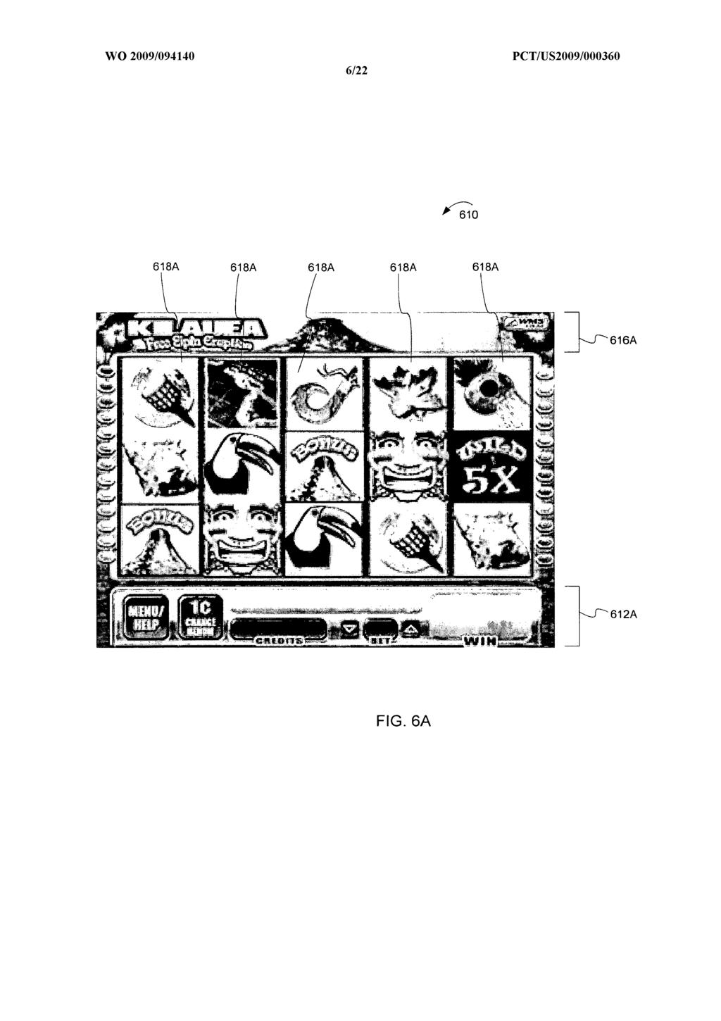
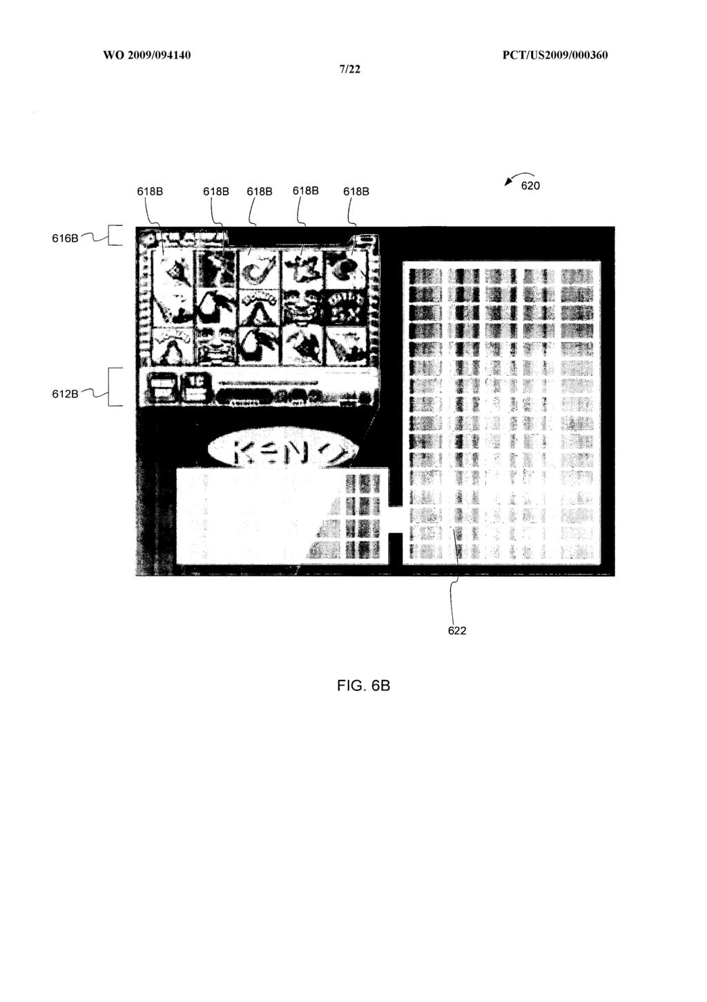
18 were in image data 520 in order to illustrate the shifting of pixel data. However it should be noted that in actual applications, the energy values would change to reflect the new updated image. Figures 6A and 6B are example "before" and "after" images used to illustrate the resizing operation of embodiments of the invention. In this example, the addition of a new game provides the indication that the screen image is to be resized. Figure 6A illustrates a "before" image 610. In general, before image 610 includes a user interface area 612, title bar 616, and reels 618. User interface area 612 includes meters (e.g., credit meters), bet amount, denomination, amount won, and help/menu button. Other information may be presented in the user interface area 612 and such information is within the scope of the inventive subject matter. Reels 618 include reel symbols that are used to display the randomly generated outcome of a wagering game. Although Figure 6A shows reels and reel symbols, other types of symbols in other configurations could be used and are within the scope of the inventive subject matter. Examples of such symbols include cards as part of a poker hand or other card came, dice, roulette balls, and other symbols used in wagering games. Title bar 616 provides the name of the wagering game, and may also provide other information or graphics. Figure 6B illustrates an "after" image 620. In the example shown, a new game 622 (a keno game for this example) has been added to the display such that two wagering games are displayed simultaneously. In order to accommodate the space required for the new game 622, the reel based game display 610 has been resized using the methods described above. In particular, user interface area 6 12A, reels 618A and title bar 616A of screen 610 have been resized to 612B, 618B and 616B respectively. Further, the user interface area 612B, reels 618B and title bar 616B have been resized at different rates by removing differing numbers of horizontal and vertical seams to reflect the relative importance. Such resizing may be accomplished as discussed above by weighting the energy levels or adjust the energy levels of the pixels of the respective areas to reflect their importance to the overall image hi some embodiments, resizing particular graphical objects may be controlled by a threshold value such that the weighting is adjusted upon reaching the threshold. This allows objects to be resized to
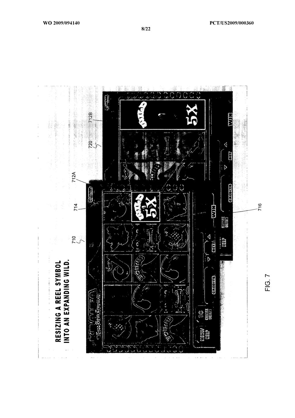
19 various limits, and the rate of resizing adjusted such that resizing slows or halts for particular graphical objects. Further, some embodiments may maintain multiple thresholds for resizing graphical objects in an image. Alternatively, once a resize threshold has been reached, the graphical object may be converted to a different representation. For example, an image representing a wagering game may be reduced in size using content aware resizing until a predetermined threshold is reached where the game is no longer easily playable. At this threshold, the wagering game image may be converted to an icon allowing the player to play other wagering games concurrently displayed on the screen. The user may then interact with the icon to resume playing the wagering game represented by the icon. Size thresholds may be used in other ways in various embodiments. For example, a symbol may be resized (either by a player or autonomously by the system). Once the symbol reaches a particular size, the symbol may be enhanced or replaced with another symbol, which may continue to be resized. For example, upon enlarging a symbol to a particular threshold, a pay table may replace or appear in the symbol. Figure 7 provides example screens 710 and 720 illustrating the resizing operation of alternative embodiments of the invention. In this example, the appearance of a particular wagering game symbol indicates the need for resizing of at least a portion of a screen image. Screen 710 illustrates a "before" image reflecting an image before resizing. The image includes reel symbols 712A, 714 and 716 on a vertical spinning reel. Reel symbol 712A is a wild symbol. Further, reel symbol 712 A is what is known as an "expanding wild", a symbol that expands during wagering game play to cover multiple symbol areas. Screen 720 is a screen image of an example screen after the wild symbol has been resized using the methods discussed above. In the example shown, horizontal seams have been added to reel symbol 712A to create expanded reel symbol 712B. The expanded wild symbol 712B covers the space occupied by symbols 714 and 716. Although reel symbols have been used in the example shown in Figures 7A and 7B, other symbols such as cards, dice, roulette balls and wheels, bingo cards and balls, etc. may be used and are within the scope of the inventive subject matter. Figure 8 provides example screens illustrating the resizing operation of
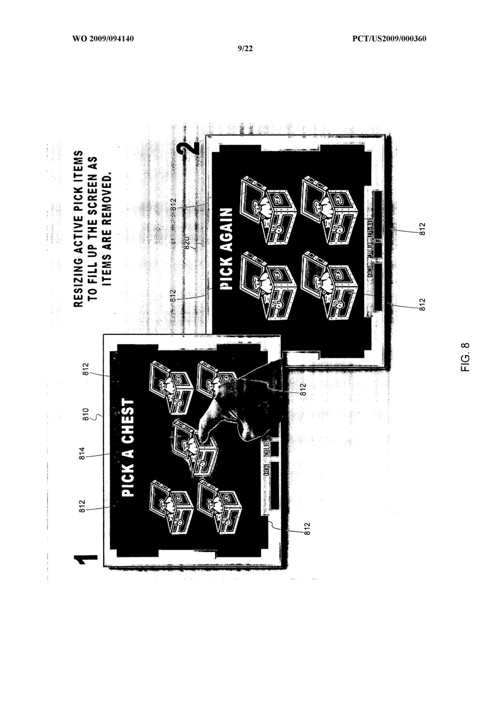
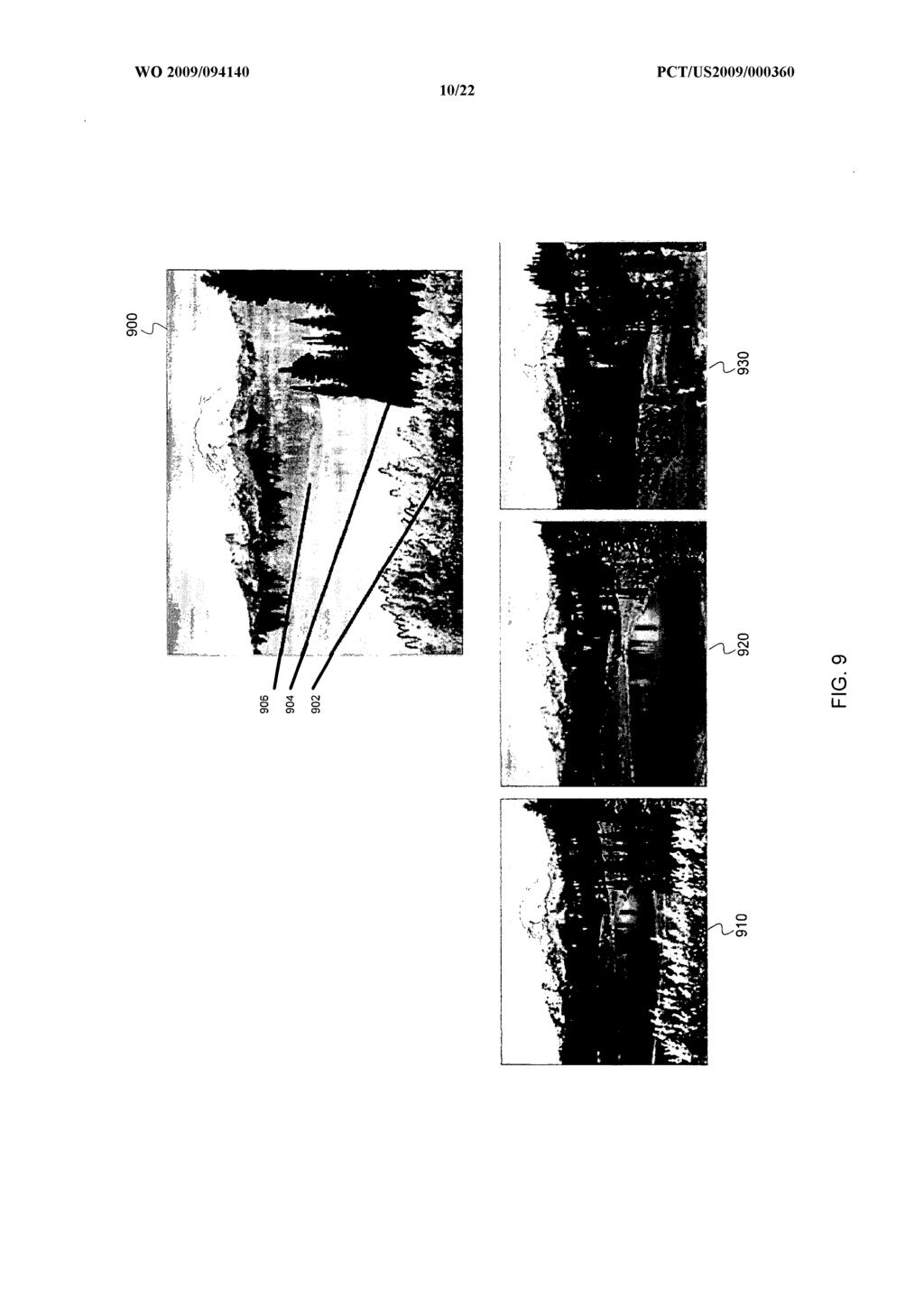
20 further alternative embodiments of the invention. In this example, the selection of a symbol indicates that at least a portion of the screen image needs to be resized. The example illustrated in Figure 8 shows a "before" image 810 and an "after" image 820. For the purposes of this example, images 810 and 820 represent screens providing an interface to select treasure chests 812, 814. Once selected, the selected treasure chest is removed from the screen. In the example shown, chest 814 has been selected as illustrated in screen image 810. The image is adjusted such that chest 814 is not shown in image 820. Further, the image is resized such that the remaining chests 812 fill in where chest 814 was removed. The resizing may be accomplished using the systems and methods described above. In some embodiments, the image portion representing chests 812 may have their corresponding energy values weighted or adjusted such that seams are added to the image to expand the chests in horizontal and/or vertical directions. Thus the remaining chests appear to fill up the screen as other chests are selected and removed. Figure 9 provides example screens illustrating resizing areas of an image to simulate animation according to example embodiments of the invention. Thus in this example, the start of an animation during the presentation of a wagering game indicates that portions of the screen image need to be resized. In the example shown, a multiplane scene animation of a scene 900 is described. In this example, the image for scene 900 is divided into a foreground area 902, a middleground area 904, and a background area 906. The foreground, middleground, and background areas may be encoded in a variety of manners. In order to animate the scene, each areas is resized at different rates to create the illusion of moving through distance. For example, foreground area 902 may be resized at a greater rate than the middleground area 904, which in turn is resized at a greater rate than background area 906. Background area 906 may be resized at the lowest rate, or not resized at all. The resizing of each individual area may be accomplished using the seam carving method described above, in which seams are added to expand an area and seams are removed to shrink an area. Such expansion and shrinking through resizing provides the illusion of movement either close to, or away from the scene 900. Screen images 910, 920 and 930 illustrates the change in the size of the foreground, middleground and background areas at various points in time as the animation progresses. Those of
21 skill in the art will appreciate that although three areas have been shown in this example, that other numbers of areas may be used and are within the scope of the inventive subject matter. Figure 10 is a flowchart illustrating a method 1000 for keying pick areas of graphical images for a wagering game machine according to example embodiments. In some embodiments, the method begins at block 1002 by initiating the presentation of a wagering game upon which monetary value may be wagered. The wagering game may be any type of wagering game such as video versions of a slots, poker, keno, bingo, pachinko, craps or any other type of wagering game. The wagering game has graphical objects that define elements of image to be displayed for the wagering game. For example, graphical objects may be used to define and render reels, symbols, tokens, characters, text, fields, backgrounds or any other object that is displayed as part of an image for a wagering game or a bonus game of a wagering game. Some or all of the graphical objects may be pickable objects, that is, they may be capable of being selected by a user interface utilizing a touch screen or pointer device. At block 1004, a system executing the method receives keys that represent the importance of certain graphical objects in the image. For example, the pickable objects may be keyed as "important" such that they are not resized as much as other parts of the image. The keying may be used to adjust or determine weights or energy levels in the seam carving method described above such that the important objects are not resized as much as other objects. In some embodiments, keying an object is accomplished by isolating the important object on the screen, perhaps by using a simple key color, or by determining saturation levels of the graphic. At block 1006, a system executing the method receives an indication that an image, or portion of an image is to be resized. The resizing of an image may be indicated based on a variety of events or factors. For example, the user may have indicated that the screen is to be resized using a user interface, thereby causing the content aware methods described above to resize the image. Alternatively, the system may determine that the image is to be resized in response the addition or change to wagering game, user interface element, wagering game portal interface element, help screen images, advertising images or other change resulting in the addition or removal of elements from a current
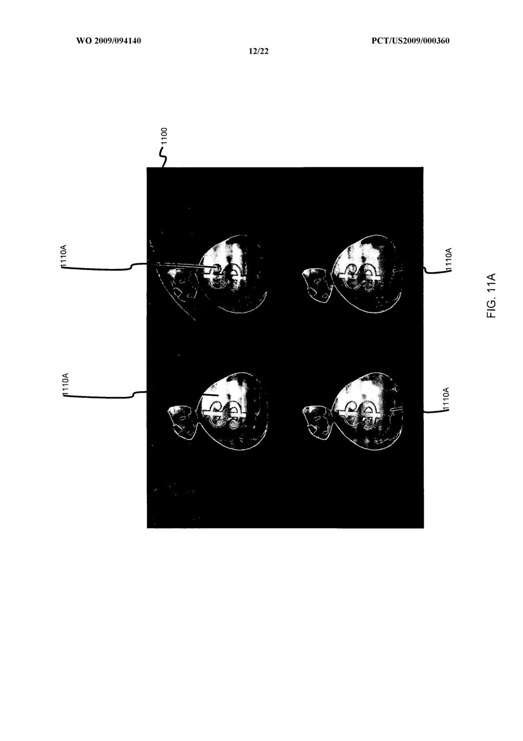
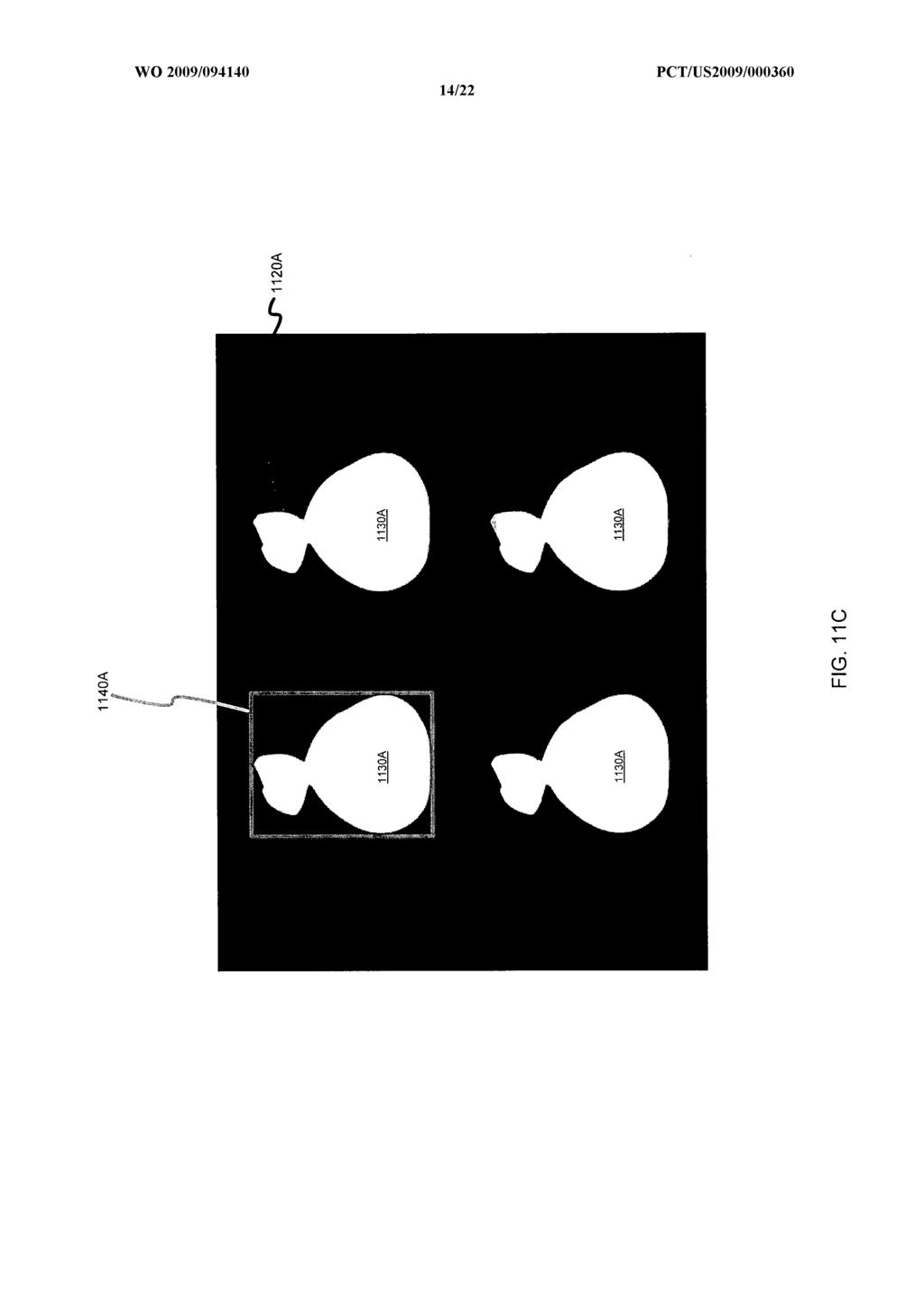
22 screen image. At block 1008, the system resizes the image. As noted above, the system analyzes the content as described above with reference to block 406 in order to determine how the image is to be resized. Further, as noted above, pixel energy values may be used to determine how the image is to be resized. Additionally, the key values may be analyzed received at block 1004 may be used to determine how the image to be resized or to adjust the energy value or weighting. The system then resizes the image according to the content analysis of block 406 and any resizing parameters that have been provided. As discussed above, in some embodiments, the system performs seam carving to repeatedly remove (decreasing image size) or add (increasing image size) one or more horizontal and/or vertical seams for the image until the image reaches a desired size. In some embodiments, graphical elements that have been keyed as important (e.g. pickable items) may be limited with respect to how small or how large the element may become after resizing. Imposing such limits is desirable because it prevents pickable items from becoming too small. At block 1010, the pick area for the pickable items in the image is adjusted such that it matches the size of the resized pickable graphic elements. At block 1012, the resized display image is displayed. Figures l l A - H D are block diagrams illustrating example images portions used to illustrate keying pickable objects and pick areas according to embodiments of the invention. Figure 1IA illustrates an initial screen image 1100, with assorted pickable objects 111OA (e.g., money bags) positioned on screen. Screen image 1100 may be a full screen image. Figure 1I B illustrates a resized screen image 1IOOB that has been resized from initial screen 1100A. The image has been resized as indicated by the arrows in Figure 1IB. The image may be resized in response to any of a number of different events (perhaps by dragging a corner), and in the example has been resized down to a restricted smaller size (restricted because it can't be too difficult to pick from the resized objects). Resizing is accomplished using the content aware analysis described above in which horizontal and/or vertical seams have been removed from the image. The positions and size of pickable objects 111OB relative to the background have changed so as to make good use of the available space. In the example shown, the pickable objects have been
23 defined as important, and they scale less to maintain a larger pick area. As illustrated in Figure 1IB, the pickable objects 111OB (i.e., the money bags) have less background space around them as they are scaled down when compared to screen 1100A. Figure 11C illustrates keying according to an embodiment of the invention. In the example shown in Figure 11C, the pickable objects 1130A (i.e., the money bags) have been keyed as white and the background is keyed as black. In some embodiments, the visual resizing of pickable objects may be maintained with one piece of art if the pickable objects are assigned, or keyed. For this example, we can isolate the important element on the screen, perhaps by using a simple key color, or by determining a saturation levels of the graphic. The keying may also designate the touch screen element's bounding box 1140A. Figure 1ID illustrates resizing of keyed objects and bounding boxes according to embodiments of the invention m Figure 1ID, screen image 1120A has been resized to image 1120B, with the keyed objects 1130B corresponding to the resized pickable objects 1130A. Further, bounding box 1140B has been resized in accordance with the resizing of the pickable objects and their associated key. As can be seen from the above, the systems and methods illustrated above provide a mechanism for a player or system to resize the images of a wagering game where the pickable objects are changed on the fly to any size in between a maximum and minimum sizes and where the pick area is maintained as the pickable object is resized. Figure 12 is a flowchart illustrating a method 1200 for resizing layers of graphical images for a wagering game machine according to example embodiments hi some embodiments, method 1200 begins at block 1202 by initiating the presentation of a wagering game upon which monetary value may be wagered. The wagering game may be any type of wagering game such as video versions of a slots, poker, keno, bingo, pachinko, craps or any other type of wagering game. The wagering game has graphical objects that define elements of image to be displayed for the wagering game. For example, graphical objects may be used to define and render reels, symbols, tokens, characters, text, fields, backgrounds or any other object that is displayed as part of an image for a wagering game or a bonus game of a wagering game. The
24 graphical objects may be arranged in multiple layers in order to facilitate pickable objects as described above, or for convenience or efficiency in rendering a screen for a wagering game. Any number of layers may exist. At block 1204, a system executing the method receives an indication that an image, or portion of an image is to be resized. The resizing of an image may be indicated based on a variety of events or factors, as has been described above. For example, in some embodiments, an image may be resized based on the different resolutions or display capabilities of a target wagering game machine. In alternative embodiments, an image may be resized base on the addition or subtraction of other elements from a final image. Such addition or subtraction may include the addition of other wagering games to the display, the addition of help screen images, advertising images, or other images to the display, or the removal of objects from an image as the objects are selected by a user. In further alternative embodiments, the resizing of an image may be indicated when a scene is to be animated. At block 1206, the system flattens the layers into a single image. In general, flattening layers of an image combines two or more separate image layers into a single layer. At block 1208, the system then analyzes the content of the flattened image as described above with reference to block 406 of Figure 4. At block 1210, the system resizes the flattened image according to the content analysis of block 1208 and any resizing parameters that have been provided. As described above, in some embodiments, the system performs seam carving on the flattened image to repeatedly remove (decreasing image size) or add (increasing image size) one or more horizontal and/or vertical seams for the flattened image until the flattened image reaches a desired size. At block 1212, the system restores the layering for the image, separating the image layers from the flattened and resized image. The layers thus reflect the resizing performed at block The system may use keys or indicators in the image data to determine the appropriate layer for various portions of the image. Separating the flattened image into layers is desirable because it allows for system and players to interact in an appropriate manner after the layers are resized. At block 1210, the resized image is displayed.
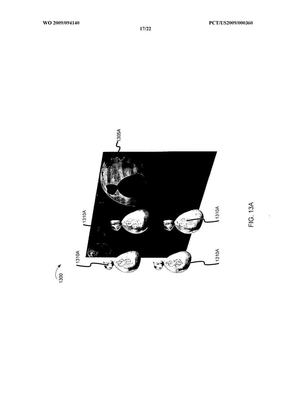
25 Figures 13A - 13D are block diagrams illustrating example images portions used to illustrate resizing layered images according to embodiments of the invention, and as described above in Figure 12. Figure 13A illustrates an initial image In the example shown image 1300 has two layers, a background layer 1305 and a second layer having images of pickable items 1310 (e.g., treasure bags). It should be noted that while two layers are illustrated in Figure 13A, other numbers of layers could be used and are within the scope of the inventive subject matter. For example, reels, bonus games and other wagering game elements may be placed in various layers. Figure 13B illustrates an image 1320A after the layers in image 1300 have been flatted. Pickable items 1310 are now part of layer 1320A. Figure 13C illustrates a resized image 1320B that represents image 1320A after it has been resized using the methods described above. For example, seam carving or other content aware resizing methods may be applied to the image to remove portions of the image that are not important to the overall image. Figure 13D illustrates an image 1330 where the layers have been separated from the flatted image 1320B. Pickable elements 1320B are illustrated in a layer that has been separated from background layer 1305B. Example Wagering Game Machine Figure 14 is a perspective view of a wagering game machine, according to example embodiments of the invention. Referring to Figure 14, a wagering game machine 1400 is used in gaming establishments, such as casinos. According to embodiments, the wagering game machine 1400 can be any type of wagering game machine and can have varying structures and methods of operation. For example, the wagering game machine 1400 can be an electromechanical wagering game machine configured to play mechanical slots, or it can be an electronic wagering game machine configured to play video casino games, such as blackjack, slots, keno, poker, blackjack, roulette, etc. The wagering game machine 1400 comprises a housing 1412 and includes input devices, including value input devices 1418 and a player input device For output, the wagering game machine 1400 includes a primary display 1414 for displaying information about a basic wagering game. The
26 primary display 1414 can also display information about a bonus wagering game and a progressive wagering game. The wagering game machine 1400 also includes a secondary display 1416 for displaying wagering game events, wagering game outcomes, and/or signage information. While some components of the wagering game machine 1400 are described herein, numerous other elements can exist and can be used in any number or combination to create varying forms of the wagering game machine The value input devices 1418 can take any suitable form and can be located on the front of the housing The value input devices 1418 can receive currency and/or credits inserted by a player. The value input devices 1418 can include coin acceptors for receiving coin currency and bill acceptors for receiving paper currency. Furthermore, the value input devices 1418 can include ticket readers or barcode scanners for reading information stored on vouchers, cards, or other tangible portable storage devices. The vouchers or cards can authorize access to central accounts, which can transfer money to the wagering game machine The player input device 1424 comprises a plurality of push buttons on a button panel 1426 for operating the wagering game machine In addition, or alternatively, the player input device 1424 can comprise a touch screen 1428 mounted over the primary display 1414 and/or secondary display The various components of the wagering game machine 1400 can be connected directly to, or contained within, the housing Alternatively, some of the wagering game machine's components can be located outside of the housing 1412, while being communicatively coupled with the wagering game machine 1400 using any suitable wired or wireless communication technology. The operation of the basic wagering game can be displayed to the player on the primary display The primary display 1414 can also display a bonus game associated with the basic wagering game. The primary display 1414 can include a cathode ray tube (CRT), a high resolution liquid crystal display (LCD), a plasma display, light emitting diodes (LEDs), or any other type of display suitable for use in the wagering game machine Alternatively, the primary display 1414 can include a number of mechanical reels to display the outcome. In Figure 14, the wagering game machine 1400 is an "upright" version in which the primary display 1414 is oriented vertically relative to the player.
27 Alternatively, the wagering game machine can be a "slant-top" version in which the primary display 1414 is slanted at about a thirty-degree angle toward the player of the wagering game machine In yet another embodiment, the wagering game machine 1400 can exhibit any suitable form factor, such as a free standing model, bartop model, mobile handheld model, or workstation console model. Further, in some embodiments, the wagering game machine 1400 may be include an attached chair assembly, and may include audio speakers designed to provide an enhanced audio environment. For example, a "surround sound" system may be included as part of the wagering game machine and may be integrated with the attached chair. A player begins playing a basic wagering game by making a wager via the value input device The player can initiate play by using the player input device's buttons or touch screen The basic game can include arranging a plurality of symbols along a payline 1432, which indicates one or more outcomes of the basic game. Such outcomes can be randomly selected in response to player input. At least one of the outcomes, which can include any variation or combination of symbols, can trigger a bonus game. In some embodiments, the wagering game machine 1400 can also include an information reader 1452, which can include a card reader, ticket reader, bar code scanner, RFID transceiver, or computer readable storage medium interface. In some embodiments, the information reader 1452 can be used to award complimentary services, restore game assets, track player habits, etc. Example Portable Wagering Game Machine Figure 15 shows an example embodiment of a portable wagering game machine The portable wagering game machine 1500 can include any suitable electronic handheld or mobile device configured to play a video casino game such as blackjack, slots, keno, poker, blackjack, and roulette. The wagering game machine 1500 comprises a housing 1512 and includes input devices, including a value input device 1518 and a player input device For output, the wagering game machine 1500 includes a primary display 1514, and may include a secondary display 1516, one or more speakers 1517, one or more player-accessible ports 1519 (e.g., an audio output jack for headphones, a video headset jack, etc.), and other conventional I/O devices and ports, which may or
28 may not be player-accessible. In the embodiment depicted in Figure 15, the wagering game machine 1500 includes a secondary display 1516 that is rotatable relative to the primary display The optional secondary display 1516 can be fixed, movable, and/or detachable/attachable relative to the primary display Either the primary display 1514 and/or secondary display 1516 can be configured to display any aspect of a non-wagering game, wagering game, secondary game, bonus game, progressive wagering game, group game, sharedexperience game or event, game event, game outcome, scrolling information, text messaging, s, alerts or announcements, broadcast information, subscription information, and wagering game machine status. The player-accessible value input device 1518 can comprise, for example, a slot located on the front, side, or top of the casing 1512 configured to receive credit from a stored-value card (e.g., casino card, smart card, debit card, credit card, etc.) inserted by a player. The player-accessible value input device 1518 can also comprise a sensor (e.g., an RF sensor) configured to sense a signal (e.g., an RF signal) output by a transmitter (e.g., an RF transmitter) carried by a player. The player-accessible value input device 1518 can also or alternatively include a ticket reader, or barcode scanner, for reading information stored on a credit ticket, a card, or other tangible portable credit or funds storage device. The credit ticket or card can also authorize access to a central account, which can transfer monetary value to the wagering game machine Still other player-accessible value input devices 1518 can require the use of touch keys 1530 on the touch-screen display (e.g., primary display 1514 and/or secondary display 1516) or player input devices Upon entry of player identification information and, preferably, secondary authorization information (e.g., a password, PIN number, stored value card number, predefined key sequences, etc.), the player can be permitted to access a player's account. As one potential optional security feature, the wagering game machine 1500 can be configured to permit a player to only access an account the player has specifically set up for the wagering game machine Other conventional security features can also be utilized to, for example, prevent unauthorized access to a player's account, to minimize an impact of any unauthorized access to a player's account, or to prevent unauthorized access to any personal information or funds temporarily stored on the wagering game machine 1500.
29 The player-accessible value input device 1518 can itself comprise or utilize a biometric player information reader which permits the player to access available funds on a player's account, either alone or in combination with another of the aforementioned player-accessible value input devices In an embodiment wherein the player-accessible value input device 1518 comprises a biometric player information reader, transactions such as an input of value to the wagering game machine 1510, a transfer of value from one player account or source to an account associated with the wagering game machine 1500, or the execution of another transaction, for example, could all be authorized by a biometric reading, which could comprise a plurality of biometric readings, from the biometric device. Alternatively, to enhance security, a transaction can be optionally enabled only by a two-step process in which a secondary source confirms the identity indicated by a primary source. For example, a player-accessible value input device 1518 comprising a biometric player information reader can require a confirmatory entry from another biometric player information reader 1552, or from another source, such as a credit card, debit card, player ID card, fob key, PIN number, password, hotel room key, etc. Thus, a transaction can be enabled by, for example, a combination of the personal identification input (e.g., biometric input) with a secret PIN number, or a combination of a biometric input with an authentication fob input, or a combination of a fob input with a PIN number, or a combination of a credit card input with a biometric input. Essentially, any two independent sources of identity, one of which is secure or personal to the player (e.g., biometric readings, PIN number, password, etc.) could be utilized to provide enhanced security prior to the electronic transfer of any funds. In another aspect, the value input device 1518 can be provided remotely from the wagering game machine The player input device 1524 may include a plurality of push buttons on a button panel for operating the wagering game machine In addition, or alternatively, the player input device 1524 can comprise a touch screen mounted to the primary display 1514 and/or secondary display In one aspect, the touch screen is matched to a display screen having one or more selectable touch keys 1530 selectable by a user's touching of the associated area of the screen using a finger or a tool, such as a stylus pointer. A player enables a desired
30 function either by touching the touch screen at an appropriate touch key 1530 or by pressing an appropriate push button on the button panel. The touch keys 1530 can be used to implement the same functions as push buttons. Alternatively, the push buttons 1526 can provide inputs for one aspect of the operating the game, while the touch keys 1530 can allow for input needed for another aspect of the game. The various components of the wagering game machine 1500 can be connected directly to, or contained within, the casing 1512, as seen in Figure 15, or can be located outside the casing 1512 and connected to the casing 1512 via a variety of wired (tethered) or wireless connection methods. Thus, the wagering game machine 1500 can comprise a single unit or a plurality of interconnected (e.g., wireless connections) parts which can be arranged to suit a player's preferences. The operation of the basic wagering game on the wagering game machine 1500 is displayed to the player on the primary display The primary display 1514 can also display a bonus game associated with the basic wagering game. The primary display 1514 preferably takes the form of a high resolution LCD, a plasma display, an LED, or any other type of display suitable for use in the wagering game machine The size of the primary display 1514 can vary from, for example, about a 2-3" display to a 15" or 17" display. In at least some embodiments, the primary display 1514 is a 7"- 10" display. In one embodiment, the size of the primary display can be increased. Optionally, coatings or removable films or sheets can be applied to the display to provide desired characteristics (e.g., anti-scratch, anti-glare, bacterially-resistant and anti-microbial films, etc.). In at least some embodiments, the primary display 1514 and/or secondary display 1516 can have a 16:9 aspect ratio or other aspect ratio (e.g., 4:3). The primary display 1514 and/or secondary display 1516 can also each have different resolutions, different color schemes, and different aspect ratios. A player typically begins play of the basic wagering game on the wagering game machine 1500 by making a wager (e.g., via the value input device 1518 or an assignment of credits stored on the portable wagering game machine 1500 via the touch screen keys 1530, player input device 1524, or buttons 1526) on the wagering game machine In some embodiments, the basic game can comprise a plurality of symbols arranged in an array, and
31 includes at least one payline 1532 that indicates one or more outcomes of the basic game. Such outcomes can be randomly selected in response to the wagering input by the player. At least one of the plurality of randomly selected outcomes can be a start-bonus outcome, which can include any variations of symbols or symbol combinations triggering a bonus game. In some embodiments, the player-accessible value input device 1518 of the wagering game machine 1500 can double as a player information reader 1552 that allows for identification of a player by reading a card with information indicating the player's identity (e.g., reading a player's credit card, player ID card, smart card, etc.). The player information reader 1552 can alternatively or also comprise a bar code scanner, RFED transceiver or computer readable storage medium interface. In one embodiment, the player information reader 1552 comprises a biometric sensing device. In some embodiments, a portable wagering game machine 1500 can part of a portable wireless communication device, such as a personal digital assistant (PDA), a laptop or portable computer with wireless communication capability, a web tablet, a wireless telephone, a wireless headset, a pager, an instant messaging device, a digital camera, a television, or other device that can receive and/or transmit information wirelessly. Conclusion Systems and methods for presenting a wagering game in which a portion or elements of the wagering game are resized using seam carving have been described. Although specific embodiments have been illustrated and described herein, it will be appreciated by those of ordinary skill in the art that any arrangement which is calculated to achieve the same purpose may be substituted for the specific embodiments shown. This application is intended to cover any adaptations or variations of the inventive subject matter. The terminology used in this application is meant to include all of these environments. It is to be understood that the above description is intended to be illustrative, and not restrictive. Many other embodiments will be apparent to those of skill in the art upon reviewing the above description. Therefore, it is manifestly intended that this invention be limited only by the following claims and equivalents thereof.
32 The Abstract is provided to comply with 37 C.F.R. 1.72(b) to allow the reader to quickly ascertain the nature and gist of the technical disclosure. The Abstract is submitted with the understanding that it will not be used to limit the scope of the claims.
33 What is claimed is: CLAIMS 1. A method comprising: presenting on a wagering game machine having at least one processor a wagering game upon which monetary value may be wagered, the wagering game including one or more graphical images; receiving an indication that an image of the one or more images is to be resized; analyzing the content of the image; resizing the image according to the content; and displaying the resized image. 2. The method of claim 1, wherein analyzing the content of the image comprises determining an energy level for portions of the image and wherein resizing the image comprises removing portions of the image in accordance with the energy level. 3. The method of claim 2, wherein removing portions of the image includes removing a horizontal or vertical seam from the image. 4. The method of claim 1, wherein analyzing the content of the image comprises determining an energy level for portions of the image and wherein resizing the image comprises adding image data to the image in accordance with the energy level. 5. The method of claim 4, wherein adding image data to the image includes adding a horizontal or vertical seam from the image. 6. The method of claim 1, wherein the indication comprises an indication that a expanding wild symbol is to be displayed and wherein resizing the image comprises resizing image data representing the expanding wild symbol.
34 7. The method of claim 1, wherein the indication comprises an indication that a second wagering game is to be displayed and wherein image data representing the wagering game is resized such that the wagering game and the second wagering game may be displayed simultaneously. 8. The method of claim 1, wherein the image includes a plurality of pickable items, and wherein the indication comprises an indication that a pickable item has selected, and further wherein the image is resized such that the pickable items that have not been selected are resized to increase in size. 9. The method of claim 1, wherein the image includes a plurality of layers, and further comprising animating the image, wherein animating the images includes resizing at least some of the plurality of layers at different rates from each other. 10. The method of claim 2, further comprising adjusting the energy level for one or more graphical elements in the image. 11. The method of claim 10, wherein the graphical elements represent pickable elements and wherein the energy level is adjusted such that the pickable element is resized at a different rate from other graphical elements in the image. 12. The method of claim 10, further comprising receiving key values indicating the pickable element. 13. The method of claim 12, further comprising determining a pick box in accordance with the resized pickable element.
35 14. A computer-readable medium having stored thereon computerexecutable instructions to cause one or more processors to perform a method, the method comprising: presenting a wagering game upon which monetary value may be wagered, the wagering game including one or more graphical images in a plurality of image layers; receiving an indication that the plurality of image layers is to be resized; flattening the plurality of layers into a flattened image layer; analyzing the content of the flattened image layer; resizing the flattened image layer according to the content; separating the flattened image layer into a plurality of resized image layers; and displaying the resized image layers. 15. The computer-readable medium of claim 14, wherein analyzing the flattened image layer includes determining energy levels for portions of the image. 16. The computer-readable medium of claim 14, wherein at least one of the image layers includes pickable objects, reel symbols, or a bonus game image. 17. An apparatus comprising: a processor operable to present a wagering game upon which monetary value may be wagered, the wagering game having one or more graphical images, and further operable to receive an indication that an image is to be resized; an image resizer operable to analyze the content of the image and resize the image according to the content; and a graphics processor operable to display the resized image. 18. The apparatus of claim 17, wherein the image resizer determines an energy level for portions of the image and removes portions of the image in accordance with the energy level.
36 19. The apparatus of claim 18, wherein the image resizer removes a horizontal or vertical seam from the image. 20. The apparatus of claim 19, wherein the horizontal or vertical seam comprises a path through the image having a lower overall energy cost than other paths through the image.
37
38
39
40
41
42
43
44
45
46
47
48
49
50
51
52
53
(12) INTERNATIONAL APPLICATION PUBLISHED UNDER THE PATENT COOPERATION TREATY (PCT)
 INTERNATIONAL APPLICATION PUBLISHED UNDER THE PATENT COOPERATION TREATY (PCT)") (12) INTERNATIONAL APPLICATION PUBLISHED UNDER THE PATENT COOPERATION TREATY (PCT) (19) World Intellectual Property Organization International Bureau (10) International Publication Number (43) International
(12) INTERNATIONAL APPLICATION PUBLISHED UNDER THE PATENT COOPERATION TREATY (PCT) (19) World Intellectual Property Organization International Bureau (10) International Publication Number (43) International
TEPZZ A_T EP A1 (19) (11) EP A1 (12) EUROPEAN PATENT APPLICATION. (43) Date of publication: Bulletin 2015/10
 (11) EP A1 (12) EUROPEAN PATENT APPLICATION. (43) Date of publication: Bulletin 2015/10") (19) TEPZZ 84 9 6A_T (11) EP 2 843 926 A1 (12) EUROPEAN PATENT APPLICATION (43) Date of publication: 04.03.1 Bulletin 1/ (1) Int Cl.: H04M 19/08 (06.01) H04L 12/ (06.01) (21) Application number: 136194.
(19) TEPZZ 84 9 6A_T (11) EP 2 843 926 A1 (12) EUROPEAN PATENT APPLICATION (43) Date of publication: 04.03.1 Bulletin 1/ (1) Int Cl.: H04M 19/08 (06.01) H04L 12/ (06.01) (21) Application number: 136194.
#9 Lane 32, Wu-Fu 1 Rd., Lu-Chu, Taoyuan City (TW).
.") (12) INTERNATIONAL APPLICATION PUBLISHED UNDER THE PATENT COOPERATION TREATY (PCT) (19) World Intellectual Property Organization International Bureau (43) International Publication Date (10) International
(12) INTERNATIONAL APPLICATION PUBLISHED UNDER THE PATENT COOPERATION TREATY (PCT) (19) World Intellectual Property Organization International Bureau (43) International Publication Date (10) International
TEPZZ 996Z 5A_T EP A1 (19) (11) EP A1 (12) EUROPEAN PATENT APPLICATION. (51) Int Cl.: G06F 3/06 ( )
 (11) EP A1 (12) EUROPEAN PATENT APPLICATION. (51) Int Cl.: G06F 3/06 ( )") (19) TEPZZ 996Z A_T (11) EP 2 996 02 A1 (12) EUROPEAN PATENT APPLICATION (43) Date of publication: 16.03.16 Bulletin 16/11 (1) Int Cl.: G06F 3/06 (06.01) (21) Application number: 14184344.1 (22) Date of
(19) TEPZZ 996Z A_T (11) EP 2 996 02 A1 (12) EUROPEAN PATENT APPLICATION (43) Date of publication: 16.03.16 Bulletin 16/11 (1) Int Cl.: G06F 3/06 (06.01) (21) Application number: 14184344.1 (22) Date of
TEPZZ A_T EP A1 (19) (11) EP A1. (12) EUROPEAN PATENT APPLICATION published in accordance with Art.
 (11) EP A1. (12) EUROPEAN PATENT APPLICATION published in accordance with Art.") (19) TEPZZ 8946 9A_T (11) EP 2 894 629 A1 (12) EUROPEAN PATENT APPLICATION published in accordance with Art. 13(4) EPC (43) Date of publication: 1.07.1 Bulletin 1/29 (21) Application number: 12889136.3
(19) TEPZZ 8946 9A_T (11) EP 2 894 629 A1 (12) EUROPEAN PATENT APPLICATION published in accordance with Art. 13(4) EPC (43) Date of publication: 1.07.1 Bulletin 1/29 (21) Application number: 12889136.3
EP A2 (19) (11) EP A2 (12) EUROPEAN PATENT APPLICATION. (43) Date of publication: Bulletin 2011/39
 (11) EP A2 (12) EUROPEAN PATENT APPLICATION. (43) Date of publication: Bulletin 2011/39") (19) (12) EUROPEAN PATENT APPLICATION (11) EP 2 368 716 A2 (43) Date of publication: 28.09.2011 Bulletin 2011/39 (51) Int Cl.: B41J 3/407 (2006.01) G06F 17/21 (2006.01) (21) Application number: 11157523.9
(19) (12) EUROPEAN PATENT APPLICATION (11) EP 2 368 716 A2 (43) Date of publication: 28.09.2011 Bulletin 2011/39 (51) Int Cl.: B41J 3/407 (2006.01) G06F 17/21 (2006.01) (21) Application number: 11157523.9
EP A2 (19) (11) EP A2 (12) EUROPEAN PATENT APPLICATION. (43) Date of publication: Bulletin 2012/20
 (11) EP A2 (12) EUROPEAN PATENT APPLICATION. (43) Date of publication: Bulletin 2012/20") (19) (12) EUROPEAN PATENT APPLICATION (11) EP 2 43 301 A2 (43) Date of publication: 16.0.2012 Bulletin 2012/20 (1) Int Cl.: G02F 1/1337 (2006.01) (21) Application number: 11103.3 (22) Date of filing: 22.02.2011
(19) (12) EUROPEAN PATENT APPLICATION (11) EP 2 43 301 A2 (43) Date of publication: 16.0.2012 Bulletin 2012/20 (1) Int Cl.: G02F 1/1337 (2006.01) (21) Application number: 11103.3 (22) Date of filing: 22.02.2011
PCT WO 2007/ Al
 (12) INTERNATIONAL APPLICATION PUBLISHED UNDER THE PATENT COOPERATION TREATY (PCT) (19) World Intellectual Property Organization International Bureau (43) International Publication Date (10) International
SELECTING A HIGH-VALENCE REPRESENTATIVE IMAGE BASED ON IMAGE QUALITY. Inventors: Nicholas P. Dufour, Mark Desnoyer, Sophie Lebrecht
 Page 1 of 74 SELECTING A HIGH-VALENCE REPRESENTATIVE IMAGE BASED ON IMAGE QUALITY Inventors: Nicholas P. Dufour, Mark Desnoyer, Sophie Lebrecht TECHNICAL FIELD methods. [0001] This disclosure generally
TEPZZ A_T EP A1 (19) (11) EP A1 (12) EUROPEAN PATENT APPLICATION. (51) Int Cl.: H04S 7/00 ( ) H04R 25/00 (2006.
 (11) EP A1 (12) EUROPEAN PATENT APPLICATION. (51) Int Cl.: H04S 7/00 ( ) H04R 25/00 (2006.") (19) TEPZZ 94 98 A_T (11) EP 2 942 982 A1 (12) EUROPEAN PATENT APPLICATION (43) Date of publication: 11.11. Bulletin /46 (1) Int Cl.: H04S 7/00 (06.01) H04R /00 (06.01) (21) Application number: 141838.7
(19) TEPZZ 94 98 A_T (11) EP 2 942 982 A1 (12) EUROPEAN PATENT APPLICATION (43) Date of publication: 11.11. Bulletin /46 (1) Int Cl.: H04S 7/00 (06.01) H04R /00 (06.01) (21) Application number: 141838.7
TEPZZ 94 98_A_T EP A1 (19) (11) EP A1 (12) EUROPEAN PATENT APPLICATION. (43) Date of publication: Bulletin 2015/46
 (11) EP A1 (12) EUROPEAN PATENT APPLICATION. (43) Date of publication: Bulletin 2015/46") (19) TEPZZ 94 98_A_T (11) EP 2 942 981 A1 (12) EUROPEAN PATENT APPLICATION (43) Date of publication: 11.11.1 Bulletin 1/46 (1) Int Cl.: H04S 7/00 (06.01) H04R /00 (06.01) (21) Application number: 1418384.0
(19) TEPZZ 94 98_A_T (11) EP 2 942 981 A1 (12) EUROPEAN PATENT APPLICATION (43) Date of publication: 11.11.1 Bulletin 1/46 (1) Int Cl.: H04S 7/00 (06.01) H04R /00 (06.01) (21) Application number: 1418384.0
METHOD, COMPUTER PROGRAM AND APPARATUS FOR DETERMINING MOTION INFORMATION FIELD OF THE INVENTION
 1 METHOD, COMPUTER PROGRAM AND APPARATUS FOR DETERMINING MOTION INFORMATION FIELD OF THE INVENTION The present invention relates to motion 5tracking. More particularly, the present invention relates to
TEPZZ 889A_T EP A1 (19) (11) EP A1 (12) EUROPEAN PATENT APPLICATION. (43) Date of publication: Bulletin 2017/35
 (11) EP A1 (12) EUROPEAN PATENT APPLICATION. (43) Date of publication: Bulletin 2017/35") (19) TEPZZ 889A_T (11) EP 3 211 889 A1 (12) EUROPEAN PATENT APPLICATION (43) Date of publication:.08.17 Bulletin 17/3 (21) Application number: 163970. (22) Date of filing: 26.02.16 (1) Int Cl.: H04N 7/
(19) TEPZZ 889A_T (11) EP 3 211 889 A1 (12) EUROPEAN PATENT APPLICATION (43) Date of publication:.08.17 Bulletin 17/3 (21) Application number: 163970. (22) Date of filing: 26.02.16 (1) Int Cl.: H04N 7/
(12) Publication of Unexamined Patent Application (A)
 Publication of Unexamined Patent Application (A)") Case #: JP H9-102827A (19) JAPANESE PATENT OFFICE (51) Int. Cl. 6 H04 M 11/00 G11B 15/02 H04Q 9/00 9/02 (12) Publication of Unexamined Patent Application (A) Identification Symbol 301 346 301 311 JPO File
Case #: JP H9-102827A (19) JAPANESE PATENT OFFICE (51) Int. Cl. 6 H04 M 11/00 G11B 15/02 H04Q 9/00 9/02 (12) Publication of Unexamined Patent Application (A) Identification Symbol 301 346 301 311 JPO File
WO 2013/ Al. 14 November 2013 ( ) P O P C T
 P O P C T") (12) INTERNATIONAL APPLICATION PUBLISHED UNDER THE PATENT COOPERATION TREATY (PCT) (19) World Intellectual Property Organization International Bureau (10) International Publication Number (43) International
(12) INTERNATIONAL APPLICATION PUBLISHED UNDER THE PATENT COOPERATION TREATY (PCT) (19) World Intellectual Property Organization International Bureau (10) International Publication Number (43) International
o VIDEO A United States Patent (19) Garfinkle u PROCESSOR AD OR NM STORE 11 Patent Number: 5,530,754 45) Date of Patent: Jun.
 Garfinkle u PROCESSOR AD OR NM STORE 11 Patent Number: 5,530,754 45) Date of Patent: Jun.") United States Patent (19) Garfinkle 54) VIDEO ON DEMAND 76 Inventor: Norton Garfinkle, 2800 S. Ocean Blvd., Boca Raton, Fla. 33432 21 Appl. No.: 285,033 22 Filed: Aug. 2, 1994 (51) Int. Cl.... HO4N 7/167
United States Patent (19) Garfinkle 54) VIDEO ON DEMAND 76 Inventor: Norton Garfinkle, 2800 S. Ocean Blvd., Boca Raton, Fla. 33432 21 Appl. No.: 285,033 22 Filed: Aug. 2, 1994 (51) Int. Cl.... HO4N 7/167
(12) Patent Application Publication (10) Pub. No.: US 2008/ A1
 Patent Application Publication (10) Pub. No.: US 2008/ A1") (19) United States US 2008O144051A1 (12) Patent Application Publication (10) Pub. No.: US 2008/0144051A1 Voltz et al. (43) Pub. Date: (54) DISPLAY DEVICE OUTPUT ADJUSTMENT SYSTEMAND METHOD (76) Inventors:
(19) United States US 2008O144051A1 (12) Patent Application Publication (10) Pub. No.: US 2008/0144051A1 Voltz et al. (43) Pub. Date: (54) DISPLAY DEVICE OUTPUT ADJUSTMENT SYSTEMAND METHOD (76) Inventors:
Designated contracting state (EPC) AT BE BG CH CY CZ DE DK EE ES FI FR GB GR HU IE IS IT LI LT LU LV MC NL PL PT RO SE SI SK TR
 AT BE BG CH CY CZ DE DK EE ES FI FR GB GR HU IE IS IT LI LT LU LV MC NL PL PT RO SE SI SK TR") Title (en) METHOD FOR EVACUATING BUILDINGS DIVIDED INTO SECTIONS Title (de) VERFAHREN ZUR EVAKUIERUNG VON IN SEKTIONEN EINGETEILTEN GEBÄUDEN Title (fr) PROCEDE POUR EVACUER DES BATIMENTS DIVISES EN SECTIONS
Title (en) METHOD FOR EVACUATING BUILDINGS DIVIDED INTO SECTIONS Title (de) VERFAHREN ZUR EVAKUIERUNG VON IN SEKTIONEN EINGETEILTEN GEBÄUDEN Title (fr) PROCEDE POUR EVACUER DES BATIMENTS DIVISES EN SECTIONS
TEPZZ 55_Z ZA_T EP A1 (19) (11) EP A1 (12) EUROPEAN PATENT APPLICATION
 (11) EP A1 (12) EUROPEAN PATENT APPLICATION") (19) TEPZZ 55_Z ZA_T (11) EP 2 551 030 A1 (12) EUROPEAN PATENT APPLICATION (43) Date of publication: 30.01.2013 Bulletin 2013/05 (21) Application number: 12176888.1 (51) Int Cl.: B21D 28/22 (2006.01) H02K
(19) TEPZZ 55_Z ZA_T (11) EP 2 551 030 A1 (12) EUROPEAN PATENT APPLICATION (43) Date of publication: 30.01.2013 Bulletin 2013/05 (21) Application number: 12176888.1 (51) Int Cl.: B21D 28/22 (2006.01) H02K
Press Publications CMC-99 CMC-141
 Press Publications CMC-99 CMC-141 MultiCon = Meter + Controller + Recorder + HMI in one package, part I Introduction The MultiCon series devices are advanced meters, controllers and recorders closed in
Feature Codes VERSION 1.0.2
 Feature Codes VERSION 1.0.2 01 Credit Play 51 Reserved 02 Double/Nothing Feature 52 Coincident Multi-Stop Reel Symbols 03 Multi-Player 53 Reserved 04 House-Set Credit Play 54 Programming For Bill Acceptor
(12) Patent Application Publication (10) Pub. No.: US 2013/ A1
 Patent Application Publication (10) Pub. No.: US 2013/ A1") US 2013 0083040A1 (19) United States (12) Patent Application Publication (10) Pub. No.: US 2013/0083040 A1 Prociw (43) Pub. Date: Apr. 4, 2013 (54) METHOD AND DEVICE FOR OVERLAPPING (52) U.S. Cl. DISPLA
US 2013 0083040A1 (19) United States (12) Patent Application Publication (10) Pub. No.: US 2013/0083040 A1 Prociw (43) Pub. Date: Apr. 4, 2013 (54) METHOD AND DEVICE FOR OVERLAPPING (52) U.S. Cl. DISPLA
(51) Int Cl.: H04L 1/00 ( )
 Int Cl.: H04L 1/00 ( )") (19) TEPZZ Z4 497A_T (11) EP 3 043 497 A1 (12) EUROPEAN PATENT APPLICATION published in accordance with Art. 153(4) EPC (43) Date of publication: 13.07.2016 Bulletin 2016/28 (21) Application number: 14842584.6
(19) TEPZZ Z4 497A_T (11) EP 3 043 497 A1 (12) EUROPEAN PATENT APPLICATION published in accordance with Art. 153(4) EPC (43) Date of publication: 13.07.2016 Bulletin 2016/28 (21) Application number: 14842584.6
(12) Patent Application Publication (10) Pub. No.: US 2005/ A1
 Patent Application Publication (10) Pub. No.: US 2005/ A1") (19) United States US 20050008347A1 (12) Patent Application Publication (10) Pub. No.: US 2005/0008347 A1 Jung et al. (43) Pub. Date: Jan. 13, 2005 (54) METHOD OF PROCESSING SUBTITLE STREAM, REPRODUCING
(19) United States US 20050008347A1 (12) Patent Application Publication (10) Pub. No.: US 2005/0008347 A1 Jung et al. (43) Pub. Date: Jan. 13, 2005 (54) METHOD OF PROCESSING SUBTITLE STREAM, REPRODUCING
(12) Patent Application Publication (10) Pub. No.: US 2006/ A1. (51) Int. Cl. SELECT A PLURALITY OF TIME SHIFT CHANNELS
 Patent Application Publication (10) Pub. No.: US 2006/ A1. (51) Int. Cl. SELECT A PLURALITY OF TIME SHIFT CHANNELS") (19) United States (12) Patent Application Publication (10) Pub. No.: Lee US 2006OO15914A1 (43) Pub. Date: Jan. 19, 2006 (54) RECORDING METHOD AND APPARATUS CAPABLE OF TIME SHIFTING INA PLURALITY OF CHANNELS
(19) United States (12) Patent Application Publication (10) Pub. No.: Lee US 2006OO15914A1 (43) Pub. Date: Jan. 19, 2006 (54) RECORDING METHOD AND APPARATUS CAPABLE OF TIME SHIFTING INA PLURALITY OF CHANNELS
(12) United States Patent
 United States Patent") (12) United States Patent USOO71 6 1 494 B2 (10) Patent No.: US 7,161,494 B2 AkuZaWa (45) Date of Patent: Jan. 9, 2007 (54) VENDING MACHINE 5,831,862 A * 11/1998 Hetrick et al.... TOOf 232 75 5,959,869
(12) United States Patent USOO71 6 1 494 B2 (10) Patent No.: US 7,161,494 B2 AkuZaWa (45) Date of Patent: Jan. 9, 2007 (54) VENDING MACHINE 5,831,862 A * 11/1998 Hetrick et al.... TOOf 232 75 5,959,869
(12) Patent Application Publication (10) Pub. No.: US 2007/ A1
 Patent Application Publication (10) Pub. No.: US 2007/ A1") (19) United States (12) Patent Application Publication (10) Pub. No.: US 2007/0230902 A1 Shen et al. US 20070230902A1 (43) Pub. Date: Oct. 4, 2007 (54) (75) (73) (21) (22) (60) DYNAMIC DISASTER RECOVERY
(19) United States (12) Patent Application Publication (10) Pub. No.: US 2007/0230902 A1 Shen et al. US 20070230902A1 (43) Pub. Date: Oct. 4, 2007 (54) (75) (73) (21) (22) (60) DYNAMIC DISASTER RECOVERY
(12) Patent Application Publication (10) Pub. No.: US 2004/ A1
 Patent Application Publication (10) Pub. No.: US 2004/ A1") (19) United States US 2004O184531A1 (12) Patent Application Publication (10) Pub. No.: US 2004/0184531A1 Lim et al. (43) Pub. Date: Sep. 23, 2004 (54) DUAL VIDEO COMPRESSION METHOD Publication Classification
(19) United States US 2004O184531A1 (12) Patent Application Publication (10) Pub. No.: US 2004/0184531A1 Lim et al. (43) Pub. Date: Sep. 23, 2004 (54) DUAL VIDEO COMPRESSION METHOD Publication Classification
TEPZZ 797Z A T EP A2 (19) (11) EP A2 (12) EUROPEAN PATENT APPLICATION. (51) Int Cl.: G06K 9/00 ( ) G06K 9/22 (2006.
 (11) EP A2 (12) EUROPEAN PATENT APPLICATION. (51) Int Cl.: G06K 9/00 ( ) G06K 9/22 (2006.") (19) TEPZZ 797Z A T (11) EP 2 797 032 A2 (12) EUROPEAN PATENT APPLICATION (43) Date of publication: 29..14 Bulletin 14/44 (1) Int Cl.: G06K 9/00 (06.01) G06K 9/22 (06.01) (21) Application number: 1416179.4
(19) TEPZZ 797Z A T (11) EP 2 797 032 A2 (12) EUROPEAN PATENT APPLICATION (43) Date of publication: 29..14 Bulletin 14/44 (1) Int Cl.: G06K 9/00 (06.01) G06K 9/22 (06.01) (21) Application number: 1416179.4
(12) Patent Application Publication (10) Pub. No.: US 2015/ A1
 Patent Application Publication (10) Pub. No.: US 2015/ A1") US 20150358554A1 (19) United States (12) Patent Application Publication (10) Pub. No.: US 2015/0358554 A1 Cheong et al. (43) Pub. Date: Dec. 10, 2015 (54) PROACTIVELY SELECTINGA Publication Classification
US 20150358554A1 (19) United States (12) Patent Application Publication (10) Pub. No.: US 2015/0358554 A1 Cheong et al. (43) Pub. Date: Dec. 10, 2015 (54) PROACTIVELY SELECTINGA Publication Classification
International film co-production in Europe
 International film co-production in Europe A publication May 2018 Index 1. What is a co-production? 2. Legal instruments for co-production 3. Production in Europe 4. Co-production volume in Europe 5. Co-production
(51) Int Cl.: G10L 19/00 ( ) G10L 19/02 ( ) G10L 21/04 ( )
 Int Cl.: G10L 19/00 ( ) G10L 19/02 ( ) G10L 21/04 ( )") (19) TEPZZ 6Z485B_T (11) EP 2 260 485 B1 (12) EUROPEAN PATENT SPECIFICATION (45) Date of publication and mention of the grant of the patent: 03.04.2013 Bulletin 2013/14 (21) Application number: 09776910.3
(19) TEPZZ 6Z485B_T (11) EP 2 260 485 B1 (12) EUROPEAN PATENT SPECIFICATION (45) Date of publication and mention of the grant of the patent: 03.04.2013 Bulletin 2013/14 (21) Application number: 09776910.3
E. R. C. E.E.O. sharp imaging on the external surface. A computer mouse or
 USOO6489934B1 (12) United States Patent (10) Patent No.: Klausner (45) Date of Patent: Dec. 3, 2002 (54) CELLULAR PHONE WITH BUILT IN (74) Attorney, Agent, or Firm-Darby & Darby OPTICAL PROJECTOR FOR DISPLAY
(12) Patent Application Publication (10) Pub. No.: US 2003/ A1
 Patent Application Publication (10) Pub. No.: US 2003/ A1") US 2003O22O142A1 (19) United States (12) Patent Application Publication (10) Pub. No.: US 2003/0220142 A1 Siegel (43) Pub. Date: Nov. 27, 2003 (54) VIDEO GAME CONTROLLER WITH Related U.S. Application Data
US 2003O22O142A1 (19) United States (12) Patent Application Publication (10) Pub. No.: US 2003/0220142 A1 Siegel (43) Pub. Date: Nov. 27, 2003 (54) VIDEO GAME CONTROLLER WITH Related U.S. Application Data
(12) Patent Application Publication (10) Pub. No.: US 2004/ A1. Kusumoto (43) Pub. Date: Oct. 7, 2004
 Patent Application Publication (10) Pub. No.: US 2004/ A1. Kusumoto (43) Pub. Date: Oct. 7, 2004") US 2004O1946.13A1 (19) United States (12) Patent Application Publication (10) Pub. No.: US 2004/0194613 A1 Kusumoto (43) Pub. Date: Oct. 7, 2004 (54) EFFECT SYSTEM (30) Foreign Application Priority Data
US 2004O1946.13A1 (19) United States (12) Patent Application Publication (10) Pub. No.: US 2004/0194613 A1 Kusumoto (43) Pub. Date: Oct. 7, 2004 (54) EFFECT SYSTEM (30) Foreign Application Priority Data
Evolution to Broadband Triple play An EU research and policy perspective
 Evolution to Broadband Triple play An EU research and policy perspective Jeanne De Jaegher European Commission DG Information Society and Media http://www.cordis.lu/ist/directorate_d/audiovisual/index.htm
2) }25 2 O TUNE IF. CHANNEL, TS i AUDIO
 }25 2 O TUNE IF. CHANNEL, TS i AUDIO") US 20050160453A1 (19) United States (12) Patent Application Publication (10) Pub. N0.: US 2005/0160453 A1 Kim (43) Pub. Date: (54) APPARATUS TO CHANGE A CHANNEL (52) US. Cl...... 725/39; 725/38; 725/120;
US 20050160453A1 (19) United States (12) Patent Application Publication (10) Pub. N0.: US 2005/0160453 A1 Kim (43) Pub. Date: (54) APPARATUS TO CHANGE A CHANNEL (52) US. Cl...... 725/39; 725/38; 725/120;
Pivoting Object Tracking System
 Pivoting Object Tracking System [CSEE 4840 Project Design - March 2009] Damian Ancukiewicz Applied Physics and Applied Mathematics Department da2260@columbia.edu Jinglin Shen Electrical Engineering Department
TEPZZ 7 9_Z B_T EP B1 (19) (11) EP B1 (12) EUROPEAN PATENT SPECIFICATION
 (11) EP B1 (12) EUROPEAN PATENT SPECIFICATION") (19) TEPZZ 7 9_Z B_T (11) EP 2 739 2 B1 (12) EUROPEAN PATENT SPECIFICATION (4) Date of publication and mention of the grant of the patent: 27.07.16 Bulletin 16/ (21) Application number: 12823933.2 (22)
(19) TEPZZ 7 9_Z B_T (11) EP 2 739 2 B1 (12) EUROPEAN PATENT SPECIFICATION (4) Date of publication and mention of the grant of the patent: 27.07.16 Bulletin 16/ (21) Application number: 12823933.2 (22)
IN THE UNITED STATES PATENT AND TRADEMARK OFFICE TITLE OF THE INVENTION
 Atty. Docket No.: UAZ-001100PV UAZ Ref. No.: UA13-130 Provisional Application IN THE UNITED STATES PATENT AND TRADEMARK OFFICE TITLE OF THE INVENTION GESTURE IDENTIFICATION AND REPLICATION Inventors: ALON
Advanced Setup Guide
 Advanced Setup Guide The only warranties for Hewlett-Packard products and services are set forth in the express statements accompanying such products and services. Nothing herein should be construed as
(12) United States Patent (10) Patent No.: US 6,275,266 B1
 United States Patent (10) Patent No.: US 6,275,266 B1") USOO6275266B1 (12) United States Patent (10) Patent No.: Morris et al. (45) Date of Patent: *Aug. 14, 2001 (54) APPARATUS AND METHOD FOR 5,8,208 9/1998 Samela... 348/446 AUTOMATICALLY DETECTING AND 5,841,418
USOO6275266B1 (12) United States Patent (10) Patent No.: Morris et al. (45) Date of Patent: *Aug. 14, 2001 (54) APPARATUS AND METHOD FOR 5,8,208 9/1998 Samela... 348/446 AUTOMATICALLY DETECTING AND 5,841,418
UNITED STATES PATENT AND TRADEMARK OFFICE BEFORE THE PATENT TRIAL AND APPEAL BOARD. LG ELECTRONICS, INC. Petitioner. ATI TECHNOLOGIES ULC Patent Owner
 UNITED STATES PATENT AND TRADEMARK OFFICE BEFORE THE PATENT TRIAL AND APPEAL BOARD LG ELECTRONICS, INC. Petitioner v. ATI TECHNOLOGIES ULC Patent Owner Case: IPR2015-00322 Patent 6,784,879 PETITION FOR
Voluntary Product Accessibility Template
 Date: October 12, 2016 Product Name: Samsung NE Smart HealthCare TV series Product Version Number: HG43NE593SFXZA Vendor Company Name: Samsung Electronics America, Inc. Vendor Contact Name: Sylvia Lee
(12) United States Patent (10) Patent No.: US 6,462,508 B1. Wang et al. (45) Date of Patent: Oct. 8, 2002
 United States Patent (10) Patent No.: US 6,462,508 B1. Wang et al. (45) Date of Patent: Oct. 8, 2002") USOO6462508B1 (12) United States Patent (10) Patent No.: US 6,462,508 B1 Wang et al. (45) Date of Patent: Oct. 8, 2002 (54) CHARGER OF A DIGITAL CAMERA WITH OTHER PUBLICATIONS DATA TRANSMISSION FUNCTION
USOO6462508B1 (12) United States Patent (10) Patent No.: US 6,462,508 B1 Wang et al. (45) Date of Patent: Oct. 8, 2002 (54) CHARGER OF A DIGITAL CAMERA WITH OTHER PUBLICATIONS DATA TRANSMISSION FUNCTION
Data Sheet Fujitsu USB 3.0 Port Replicator PR08
 Data Sheet Fujitsu USB 3.0 Port Replicator PR08 Connect everything with a single plug The Fujitsu USB 3.0 Port Replicator PR08 is the solution for notebooks without a dedicated docking connector or in
Automatic optimization of image capture on mobile devices by human and non-human agents
 Automatic optimization of image capture on mobile devices by human and non-human agents 1.1 Abstract Sophie Lebrecht, Mark Desnoyer, Nick Dufour, Zhihao Li, Nicole A. Halmi, David L. Sheinberg, Michael
(12) Patent Application Publication (10) Pub. No.: US 2013/ A1
 Patent Application Publication (10) Pub. No.: US 2013/ A1") (19) United States US 2013 0100156A1 (12) Patent Application Publication (10) Pub. No.: US 2013/0100156A1 JANG et al. (43) Pub. Date: Apr. 25, 2013 (54) PORTABLE TERMINAL CAPABLE OF (30) Foreign Application
(19) United States US 2013 0100156A1 (12) Patent Application Publication (10) Pub. No.: US 2013/0100156A1 JANG et al. (43) Pub. Date: Apr. 25, 2013 (54) PORTABLE TERMINAL CAPABLE OF (30) Foreign Application
(12) United States Patent
 United States Patent") (12) United States Patent Ali USOO65O1400B2 (10) Patent No.: (45) Date of Patent: Dec. 31, 2002 (54) CORRECTION OF OPERATIONAL AMPLIFIER GAIN ERROR IN PIPELINED ANALOG TO DIGITAL CONVERTERS (75) Inventor:
(12) United States Patent Ali USOO65O1400B2 (10) Patent No.: (45) Date of Patent: Dec. 31, 2002 (54) CORRECTION OF OPERATIONAL AMPLIFIER GAIN ERROR IN PIPELINED ANALOG TO DIGITAL CONVERTERS (75) Inventor:
The transition to Digital Terrestrial TV and utilisation of the digital dividend in Europe
 ITU NMHH Workshop on Spectrum Management and Transition to DTT The transition to Digital Terrestrial TV and utilisation of the digital dividend in Europe Andreas Roever* Principal Administrator Broadcast
Part 1 Basic Operation
 This product is a designed for video surveillance video encode and record, it include H.264 video Compression, large HDD storage, network, embedded Linux operate system and other advanced electronic technology,
(12) Patent Application Publication (10) Pub. No.: US 2011/ A1
 Patent Application Publication (10) Pub. No.: US 2011/ A1") (19) United States US 2011 0320948A1 (12) Patent Application Publication (10) Pub. No.: US 2011/0320948 A1 CHO (43) Pub. Date: Dec. 29, 2011 (54) DISPLAY APPARATUS AND USER Publication Classification INTERFACE
(19) United States US 2011 0320948A1 (12) Patent Application Publication (10) Pub. No.: US 2011/0320948 A1 CHO (43) Pub. Date: Dec. 29, 2011 (54) DISPLAY APPARATUS AND USER Publication Classification INTERFACE
Module 8 VIDEO CODING STANDARDS. Version 2 ECE IIT, Kharagpur
 Module 8 VIDEO CODING STANDARDS Lesson 27 H.264 standard Lesson Objectives At the end of this lesson, the students should be able to: 1. State the broad objectives of the H.264 standard. 2. List the improved
Intelligent Monitoring Software IMZ-RS300. Series IMZ-RS301 IMZ-RS304 IMZ-RS309 IMZ-RS316 IMZ-RS332 IMZ-RS300C
 Intelligent Monitoring Software IMZ-RS300 Series IMZ-RS301 IMZ-RS304 IMZ-RS309 IMZ-RS316 IMZ-RS332 IMZ-RS300C Flexible IP Video Monitoring With the Added Functionality of Intelligent Motion Detection With
(12) Patent Application Publication (10) Pub. No.: US 2014/ A1
 Patent Application Publication (10) Pub. No.: US 2014/ A1") (19) United States US 2014O1 O1585A1 (12) Patent Application Publication (10) Pub. No.: US 2014/0101585 A1 YOO et al. (43) Pub. Date: Apr. 10, 2014 (54) IMAGE PROCESSINGAPPARATUS AND (30) Foreign Application
(19) United States US 2014O1 O1585A1 (12) Patent Application Publication (10) Pub. No.: US 2014/0101585 A1 YOO et al. (43) Pub. Date: Apr. 10, 2014 (54) IMAGE PROCESSINGAPPARATUS AND (30) Foreign Application
Compressed Air Management Systems SIGMA AIR MANAGER Pressure flexibility Switching losses Control losses next.
 Compressed Air Management Systems SIGMA AIR MANAGER Pressure flexibility Switching losses Control losses next.generation Sigma Air Manager Integrated performance for maximum energy savings An orchestra
DISTRIBUTION STATEMENT A 7001Ö
 Serial Number 09/678.881 Filing Date 4 October 2000 Inventor Robert C. Higgins NOTICE The above identified patent application is available for licensing. Requests for information should be addressed to:
(12) Patent Application Publication (10) Pub. No.: US 2007/ A1
 Patent Application Publication (10) Pub. No.: US 2007/ A1") US 20070011710A1 (19) United States (12) Patent Application Publication (10) Pub. No.: Chiu (43) Pub. Date: Jan. 11, 2007 (54) INTERACTIVE NEWS GATHERING AND Publication Classification MEDIA PRODUCTION
US 20070011710A1 (19) United States (12) Patent Application Publication (10) Pub. No.: Chiu (43) Pub. Date: Jan. 11, 2007 (54) INTERACTIVE NEWS GATHERING AND Publication Classification MEDIA PRODUCTION
(12) United States Patent (10) Patent No.: US 7,952,748 B2
 United States Patent (10) Patent No.: US 7,952,748 B2") US007952748B2 (12) United States Patent (10) Patent No.: US 7,952,748 B2 Voltz et al. (45) Date of Patent: May 31, 2011 (54) DISPLAY DEVICE OUTPUT ADJUSTMENT SYSTEMAND METHOD 358/296, 3.07, 448, 18; 382/299,
US007952748B2 (12) United States Patent (10) Patent No.: US 7,952,748 B2 Voltz et al. (45) Date of Patent: May 31, 2011 (54) DISPLAY DEVICE OUTPUT ADJUSTMENT SYSTEMAND METHOD 358/296, 3.07, 448, 18; 382/299,
Dell Wyse 5030 PCoIP Zero Client
 Dell Wyse 5030 PCoIP Zero Client User Guide Regulatory Model: PxN Regulatory Type: PxN001 Notes, cautions, and warnings NOTE: A NOTE indicates important information that helps you make better use of your
Accessibility Planar Touchscreens
 Accessibility Planar Touchscreens The table below is a summary of how Planar's PT touchscreen LCD monitors meet the government's standards for accessibility (Section 508). For more information about the
(12) Patent Application Publication (10) Pub. No.: US 2006/ A1. (51) Int. Cl.
 Patent Application Publication (10) Pub. No.: US 2006/ A1. (51) Int. Cl.") (19) United States US 20060034.186A1 (12) Patent Application Publication (10) Pub. No.: US 2006/0034186 A1 Kim et al. (43) Pub. Date: Feb. 16, 2006 (54) FRAME TRANSMISSION METHOD IN WIRELESS ENVIRONMENT
(19) United States US 20060034.186A1 (12) Patent Application Publication (10) Pub. No.: US 2006/0034186 A1 Kim et al. (43) Pub. Date: Feb. 16, 2006 (54) FRAME TRANSMISSION METHOD IN WIRELESS ENVIRONMENT
ITU-T Y Reference architecture for Internet of things network capability exposure
 I n t e r n a t i o n a l T e l e c o m m u n i c a t i o n U n i o n ITU-T Y.4455 TELECOMMUNICATION STANDARDIZATION SECTOR OF ITU (10/2017) SERIES Y: GLOBAL INFORMATION INFRASTRUCTURE, INTERNET PROTOCOL
Processor time 9 Used memory 9. Lost video frames 11 Storage buffer 11 Received rate 11
 Processor time 9 Used memory 9 Lost video frames 11 Storage buffer 11 Received rate 11 2 3 After you ve completed the installation and configuration, run AXIS Installation Verifier from the main menu icon
ELC-MVS01 Multi-format Control Room Automation Software
 ELC-MVS01 Multi-format Control Room Automation Software Enhanced Live-production Control System Over the years, Sony has continuously evolved the MVS platform with hardware and software that combine high
Device Management Requirements
 Device Management Requirements Approved Version 2.0 09 Feb 2016 Open Mobile Alliance OMA-RD-DM-V2_0-20160209-A [OMA-Template-ReqDoc-20160101-I] OMA-RD-DM-V2_0-20160209-A Page 2 (14) Use of this document
Boonton 4540 Remote Operation Modes
 Application Note Boonton 4540 Remote Operation Modes Mazumder Alam Product Marketing Manager, Boonton Electronics Abstract Boonton 4540 series power meters are among the leading edge instruments for most
TRANSMITTING SPORTS AND ENTERTAINMENT DATA TO WIRELESS HAND HELD DEVICES OVER A TELECOMMUNICATIONS NETWORK CROSS-REFERENCE TO RELATED APPLICATIONS
 TRANSMITTING SPORTS AND ENTERTAINMENT DATA TO WIRELESS HAND HELD DEVICES OVER A TELECOMMUNICATIONS NETWORK CROSS-REFERENCE TO RELATED APPLICATIONS [0001] This application is a continuation of U.S. Serial
Multiband Noise Reduction Component for PurePath Studio Portable Audio Devices
 Multiband Noise Reduction Component for PurePath Studio Portable Audio Devices Audio Converters ABSTRACT This application note describes the features, operating procedures and control capabilities of a
(12) Patent Application Publication (10) Pub. No.: US 2010/ A1
 Patent Application Publication (10) Pub. No.: US 2010/ A1") US 2010O283828A1 (19) United States (12) Patent Application Publication (10) Pub. No.: US 2010/0283828A1 Lee et al. (43) Pub. Date: Nov. 11, 2010 (54) MULTI-VIEW 3D VIDEO CONFERENCE (30) Foreign Application
US 2010O283828A1 (19) United States (12) Patent Application Publication (10) Pub. No.: US 2010/0283828A1 Lee et al. (43) Pub. Date: Nov. 11, 2010 (54) MULTI-VIEW 3D VIDEO CONFERENCE (30) Foreign Application
(12) United States Patent (10) Patent No.: US 7.043,750 B2. na (45) Date of Patent: May 9, 2006
 United States Patent (10) Patent No.: US 7.043,750 B2. na (45) Date of Patent: May 9, 2006") US00704375OB2 (12) United States Patent (10) Patent No.: US 7.043,750 B2 na (45) Date of Patent: May 9, 2006 (54) SET TOP BOX WITH OUT OF BAND (58) Field of Classification Search... 725/111, MODEMAND CABLE
US00704375OB2 (12) United States Patent (10) Patent No.: US 7.043,750 B2 na (45) Date of Patent: May 9, 2006 (54) SET TOP BOX WITH OUT OF BAND (58) Field of Classification Search... 725/111, MODEMAND CABLE
USOO A United States Patent (19) 11 Patent Number: 5,822,052 Tsai (45) Date of Patent: Oct. 13, 1998
 11 Patent Number: 5,822,052 Tsai (45) Date of Patent: Oct. 13, 1998") USOO5822052A United States Patent (19) 11 Patent Number: Tsai (45) Date of Patent: Oct. 13, 1998 54 METHOD AND APPARATUS FOR 5,212,376 5/1993 Liang... 250/208.1 COMPENSATING ILLUMINANCE ERROR 5,278,674
USOO5822052A United States Patent (19) 11 Patent Number: Tsai (45) Date of Patent: Oct. 13, 1998 54 METHOD AND APPARATUS FOR 5,212,376 5/1993 Liang... 250/208.1 COMPENSATING ILLUMINANCE ERROR 5,278,674
Dm 200. (12) Patent Application Publication (10) Pub. No.: US 2007/ A1. (19) United States. User. (43) Pub. Date: Oct. 18, 2007.
 Patent Application Publication (10) Pub. No.: US 2007/ A1. (19) United States. User. (43) Pub. Date: Oct. 18, 2007.") (19) United States (12) Patent Application Publication (10) Pub. No.: US 2007/0242068 A1 Han et al. US 20070242068A1 (43) Pub. Date: (54) 2D/3D IMAGE DISPLAY DEVICE, ELECTRONIC IMAGING DISPLAY DEVICE,
(19) United States (12) Patent Application Publication (10) Pub. No.: US 2007/0242068 A1 Han et al. US 20070242068A1 (43) Pub. Date: (54) 2D/3D IMAGE DISPLAY DEVICE, ELECTRONIC IMAGING DISPLAY DEVICE,
VERINT EDGEVR 200 INTELLIGENT DIGITAL VIDEO RECORDER (Rev A)
") VERINT EDGEVR 200 INTELLIGENT DIGITAL VIDEO RECORDER (Rev A) TECHNICAL SPECIFICATIONS SECURITY SYSTEM DIVISION 28 ELECTRONIC SAFETY AND SECURITY LEVEL 1 28 20 00 ELECTRONIC SURVEILLANCE LEVEL 2 28 23 00
VERINT EDGEVR 200 INTELLIGENT DIGITAL VIDEO RECORDER (Rev A) TECHNICAL SPECIFICATIONS SECURITY SYSTEM DIVISION 28 ELECTRONIC SAFETY AND SECURITY LEVEL 1 28 20 00 ELECTRONIC SURVEILLANCE LEVEL 2 28 23 00
Selection Results for the STEP traineeships published on the 9th of April, 2018
 Selection Results for the STEP traineeships published on the 9th of April, 2018 Please, have in mind: - The selection results are at the moment incomplete. We are still waiting for the feedback from several
Licensing and Authorisation Procedures Lessons from the MAVISE task force
 Licensing and Authorisation Procedures Lessons from the MAVISE task force May 2017 Gilles Fontaine Head of Department for Market Information Background MAVISE task force -> identification of differences
Summary Table Voluntary Product Accessibility Template. Supporting Features. Supports. Supports. Supports. Supports
 Date: 15 November 2017 Name of Product: Lenovo 500 Wireless Combo Keyboard and Mouse Summary Table Voluntary Product Accessibility Template Section 1194.21 Software Applications and Operating Systems Section
(12) Patent Application Publication (10) Pub. No.: US 2015/ A1
 Patent Application Publication (10) Pub. No.: US 2015/ A1") (19) United States (12) Patent Application Publication (10) Pub. No.: US 2015/0116196A1 Liu et al. US 2015O11 6 196A1 (43) Pub. Date: Apr. 30, 2015 (54) (71) (72) (73) (21) (22) (86) (30) LED DISPLAY MODULE,
(19) United States (12) Patent Application Publication (10) Pub. No.: US 2015/0116196A1 Liu et al. US 2015O11 6 196A1 (43) Pub. Date: Apr. 30, 2015 (54) (71) (72) (73) (21) (22) (86) (30) LED DISPLAY MODULE,
STB Front Panel User s Guide
 S ET-TOP BOX FRONT PANEL USER S GUIDE 1. Introduction The Set-Top Box (STB) Front Panel has the following demonstration capabilities: Pressing 1 of the 8 capacitive sensing pads lights up that pad s corresponding
EP A2 (19) (11) EP A2 (12) EUROPEAN PATENT APPLICATION. (43) Date of publication: Bulletin 2009/24
 (11) EP A2 (12) EUROPEAN PATENT APPLICATION. (43) Date of publication: Bulletin 2009/24") (19) (12) EUROPEAN PATENT APPLICATION (11) EP 2 068 378 A2 (43) Date of publication:.06.2009 Bulletin 2009/24 (21) Application number: 08020371.4 (51) Int Cl.: H01L 33/00 (2006.01) G02F 1/13357 (2006.01)
(19) (12) EUROPEAN PATENT APPLICATION (11) EP 2 068 378 A2 (43) Date of publication:.06.2009 Bulletin 2009/24 (21) Application number: 08020371.4 (51) Int Cl.: H01L 33/00 (2006.01) G02F 1/13357 (2006.01)
(12) Patent Application Publication (10) Pub. No.: US 2012/ A1
 Patent Application Publication (10) Pub. No.: US 2012/ A1") (19) United States US 2012O114336A1 (12) Patent Application Publication (10) Pub. No.: US 2012/0114336A1 Kim et al. (43) Pub. Date: May 10, 2012 (54) (75) (73) (21) (22) (60) NETWORK DGITAL SIGNAGE SOLUTION
(19) United States US 2012O114336A1 (12) Patent Application Publication (10) Pub. No.: US 2012/0114336A1 Kim et al. (43) Pub. Date: May 10, 2012 (54) (75) (73) (21) (22) (60) NETWORK DGITAL SIGNAGE SOLUTION
(12) Patent Application Publication (10) Pub. No.: US 2007/ A1
 Patent Application Publication (10) Pub. No.: US 2007/ A1") US 20070O8391 OA1 (19) United States (12) Patent Application Publication (10) Pub. No.: US 2007/0083910 A1 Haneef et al. (43) Pub. Date: Apr. 12, 2007 (54) METHOD AND SYSTEM FOR SEAMILESS Publication Classification
US 20070O8391 OA1 (19) United States (12) Patent Application Publication (10) Pub. No.: US 2007/0083910 A1 Haneef et al. (43) Pub. Date: Apr. 12, 2007 (54) METHOD AND SYSTEM FOR SEAMILESS Publication Classification
Systems and methods of camera-based fingertip tracking
 University of Central Florida UCF Patents Patent Systems and methods of camera-based fingertip tracking 6-12-2012 Andrew Sugaya University of Central Florida Find similar works at: http://stars.library.ucf.edu/patents
Product Information. EIB 700 Series External Interface Box
 Product Information EIB 700 Series External Interface Box June 2013 EIB 700 Series The EIB 700 units are external interface boxes for precise position measurement. They are ideal for inspection stations
SQTR-2M ADS-B Squitter Generator
 SQTR-2M ADS-B Squitter Generator Operators Manual REVISION A B C D E F G H J K L M N P R S T U V W X Y Z December 2011 KLJ Instruments 15385 S. 169 Highway Olathe, KS 66062 www.kljinstruments.com NOTICE:
(12) United States Patent
 United States Patent") (12) United States Patent USOO9678590B2 (10) Patent No.: US 9,678,590 B2 Nakayama (45) Date of Patent: Jun. 13, 2017 (54) PORTABLE ELECTRONIC DEVICE (56) References Cited (75) Inventor: Shusuke Nakayama,
(12) United States Patent USOO9678590B2 (10) Patent No.: US 9,678,590 B2 Nakayama (45) Date of Patent: Jun. 13, 2017 (54) PORTABLE ELECTRONIC DEVICE (56) References Cited (75) Inventor: Shusuke Nakayama,
Voluntary Product Accessibility Template
 Date: May 18th, 2015 Product Name: Samsung DB D Series Large Format Displays Product Version Number: DB22D-T Vendor Company Name: Samsung Electronics America, Inc. Vendor Contact Name: Kevin Schroll Vendor
(12) Patent Application Publication (10) Pub. No.: US 2012/ A1. MOHAPATRA (43) Pub. Date: Jul. 5, 2012
 Patent Application Publication (10) Pub. No.: US 2012/ A1. MOHAPATRA (43) Pub. Date: Jul. 5, 2012") US 20120169931A1 (19) United States (12) Patent Application Publication (10) Pub. No.: US 2012/0169931 A1 MOHAPATRA (43) Pub. Date: Jul. 5, 2012 (54) PRESENTING CUSTOMIZED BOOT LOGO Publication Classification
US 20120169931A1 (19) United States (12) Patent Application Publication (10) Pub. No.: US 2012/0169931 A1 MOHAPATRA (43) Pub. Date: Jul. 5, 2012 (54) PRESENTING CUSTOMIZED BOOT LOGO Publication Classification
icon H600: Network centric visualization
 icon H600: Network centric visualization NEW YORK LONDON TOKYO High-definition, multi-site information sharing revolutionizes the way you work as a team Easy operation using wireless mouse and keyboard
Customized electronic part transport in the press shop siemens.com/metalforming
 Press handling solutions Customized electronic part transport in the press shop siemens.com/metalforming Your handling. Your press. Your solution. Cost-effective workpiece transport is essential for presses.
Re:connect M 203. RS232 Interface Revox. Dominating Entertainment. Revox of Switzerland. E 2.03
 of Re:connect M 203 RS232 Interface Revox Dominating Entertainment. Revox of Switzerland. E 2.03 Attention! After updating the firmware to version 2.00 or higher, we recommend completely resetting the
Cyclone V5 Teletext & Text Publishing System System Overview
 Cyclone V5 Teletext & Text Publishing System System Overview The Cyclone Teletext System offers broadcasters and Teletext service operators a complete and inexpensive solution for the preparation, storage
Software Quick Manual
 XX177-24-00 Virtual Matrix Display Controller Quick Manual Vicon Industries Inc. does not warrant that the functions contained in this equipment will meet your requirements or that the operation will be
(12) United States Patent
 United States Patent") USOO9709605B2 (12) United States Patent Alley et al. (10) Patent No.: (45) Date of Patent: Jul.18, 2017 (54) SCROLLING MEASUREMENT DISPLAY TICKER FOR TEST AND MEASUREMENT INSTRUMENTS (71) Applicant: Tektronix,
USOO9709605B2 (12) United States Patent Alley et al. (10) Patent No.: (45) Date of Patent: Jul.18, 2017 (54) SCROLLING MEASUREMENT DISPLAY TICKER FOR TEST AND MEASUREMENT INSTRUMENTS (71) Applicant: Tektronix,
The Extron MGP 464 is a powerful, highly effective tool for advanced A/V communications and presentations. It has the
 MGP 464: How to Get the Most from the MGP 464 for Successful Presentations The Extron MGP 464 is a powerful, highly effective tool for advanced A/V communications and presentations. It has the ability
IoT Toolbox Mobile Application User Manual
 Rev. 0 19 December 2017 User Manual Document information Info Keywords Abstract Content User Manual, IoT, Toolbox The IoT Toolbox is a mobile application developed by NXP Semiconductors and designed for
(12) Patent Application Publication (10) Pub. No.: US 2016/ A1
 Patent Application Publication (10) Pub. No.: US 2016/ A1") (19) United States (12) Patent Application Publication (10) Pub. No.: US 2016/0080549 A1 YUAN et al. US 2016008.0549A1 (43) Pub. Date: Mar. 17, 2016 (54) (71) (72) (73) MULT-SCREEN CONTROL METHOD AND DEVICE
(19) United States (12) Patent Application Publication (10) Pub. No.: US 2016/0080549 A1 YUAN et al. US 2016008.0549A1 (43) Pub. Date: Mar. 17, 2016 (54) (71) (72) (73) MULT-SCREEN CONTROL METHOD AND DEVICE
of Loewe E 2.10_m1 1
 of Loewe E 2.10_m1 1 Attention! After updating the M203 firmware to version 2.00 or higher, we recommend completely resetting the M203 interface by pressing the Disable softkey on setup page #2 for several
R&S WMS32 Wireless Measurement System Software Specifications
 R&S WMS32 Wireless Measurement System Software Specifications Data Sheet Version 03.00 8 CONTENTS General... 3 Software version... 3 System requirements... 3 Options for the R&S TS8997 test system with
(12) Patent Application Publication (10) Pub. No.: US 2015/ A1
 Patent Application Publication (10) Pub. No.: US 2015/ A1") (19) United States US 2015.0054800A1 (12) Patent Application Publication (10) Pub. No.: US 2015/0054800 A1 KM et al. (43) Pub. Date: Feb. 26, 2015 (54) METHOD AND APPARATUS FOR DRIVING (30) Foreign Application
(19) United States US 2015.0054800A1 (12) Patent Application Publication (10) Pub. No.: US 2015/0054800 A1 KM et al. (43) Pub. Date: Feb. 26, 2015 (54) METHOD AND APPARATUS FOR DRIVING (30) Foreign Application