Bruce Chubb s Computer/Model Railroad Interface (C/MRI) 101- The Basics
|
|
|
- Harry Lewis
- 5 years ago
- Views:
Transcription
1 Bruce Chubb s Computer/Model Railroad Interface (C/MRI) 101- The Basics By Jay Beckham james@thebeckhams.us Visit the layout Sunday Afternoon 1
2 My presentation is based in part on Bruce Chubb s presentations used with his permission. I am grateful that he not only agreed to my use of his presentations but furnished me the presentations which I have modified and adapted. First I would like to briefly present some electronic/electrical fundamentals that confused me when I first got into building and using the C/MRI system. Then I will cover the basic parts that makeup the signaling system and CTC. 2
3 Basic Electronics 101 In C/MRI grounding a circuit turns it on and no ground turns it off. This is just the opposite of what we would normally think. This method is called Current-Sinking and it the default method used by C/MRI devices. In house wiring we put the wall switch on the hot side of the circuit. In C/MRI we would ground an LED to make it light or ground the terminal on the switch machine circuit (SMC12) to make it throw the turnout to the diverging route. And the occupancy detector grounds the pin on an Input board to tell the computer that a electrical block is occupied. 3
4 Example C/MRI application areas: Optimized occupancy detection (OD and DCCOD) Signaling systems (very simple, ABS, APB and CTC) Interface with Command Control including DCC Staging track control (manual to fully automated) Grade crossing warning systems (PGCC) Turnout control (including software diode matrix) Junction and terminal interlocking Fast time clocks and layout-room lighting Driving real-time engine/dispatcher simulators Automated operations Reducing layout wiring 4

5 A very extensive series of articles about C/MRI can be found in Railroad Model Craftsman starting with the December 2015 issue. This series consists of 14 parts concluding with the April 2017 issue. Signaling in general and C/MRI is covered in great detail in this series. Well worth the time it will take to read all the parts. 5

6 Signaling Basics covered in a 4-part series: Signaling Made Easier January through April 2004 Model Railroader Magazine This series is an excellent source for getting started in Signaling and the C/MRI Copies are available directly from Kalmbach and from NMRA s Kalmbach Memorial Library 6

7 32 pages in the March 2007 issue of Scale Rails covering: State-of-the-Art Electronics to Enhance Operations Sunset Valley Oregon System My Life with Bruce and the Sunset Valley by Janet Chubb 7

8 An updated V3.1 User s Manual now available If you have V3.0 then you do not need V3.1 8
9 During this presentation we will cover: Interfacing made easier Block occupancy detection Signaling and turnout control Centralized Traffic Control Systems System assembly and simplified wiring 9
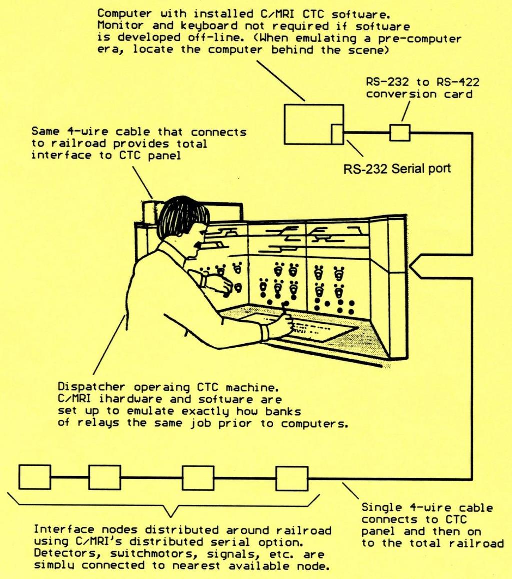
10 Interfacing your railroad to a computer is as easy as connecting a single super mini-node card (SMINI) to your computer s serial port 48 outputs for driving signals, switch motors and panel LEDs 24 inputs for reading block occupancy detectors, switch position and pushbuttons Can use USB port with USB to RS232 converter cable 10

11 SMINI CARD 11

12 Simply connect each signal, switch motor, detector, etc. to the SMINI 12

13 Distributed serial: Up to 128 nodes Devices connect to nearest node Use maxi-node for concentrated I/O Everything connects w/single 4-wire cable 72 I/O per SMINI 2048 I/O capacity per MAXI-node 262,144 total I/O capacity 13
")
14 Need more I/O, simply plug in another I/O card Each card adds 32 inputs or outputs up maximum of 64 cards per node (2480 I/O lines) 14

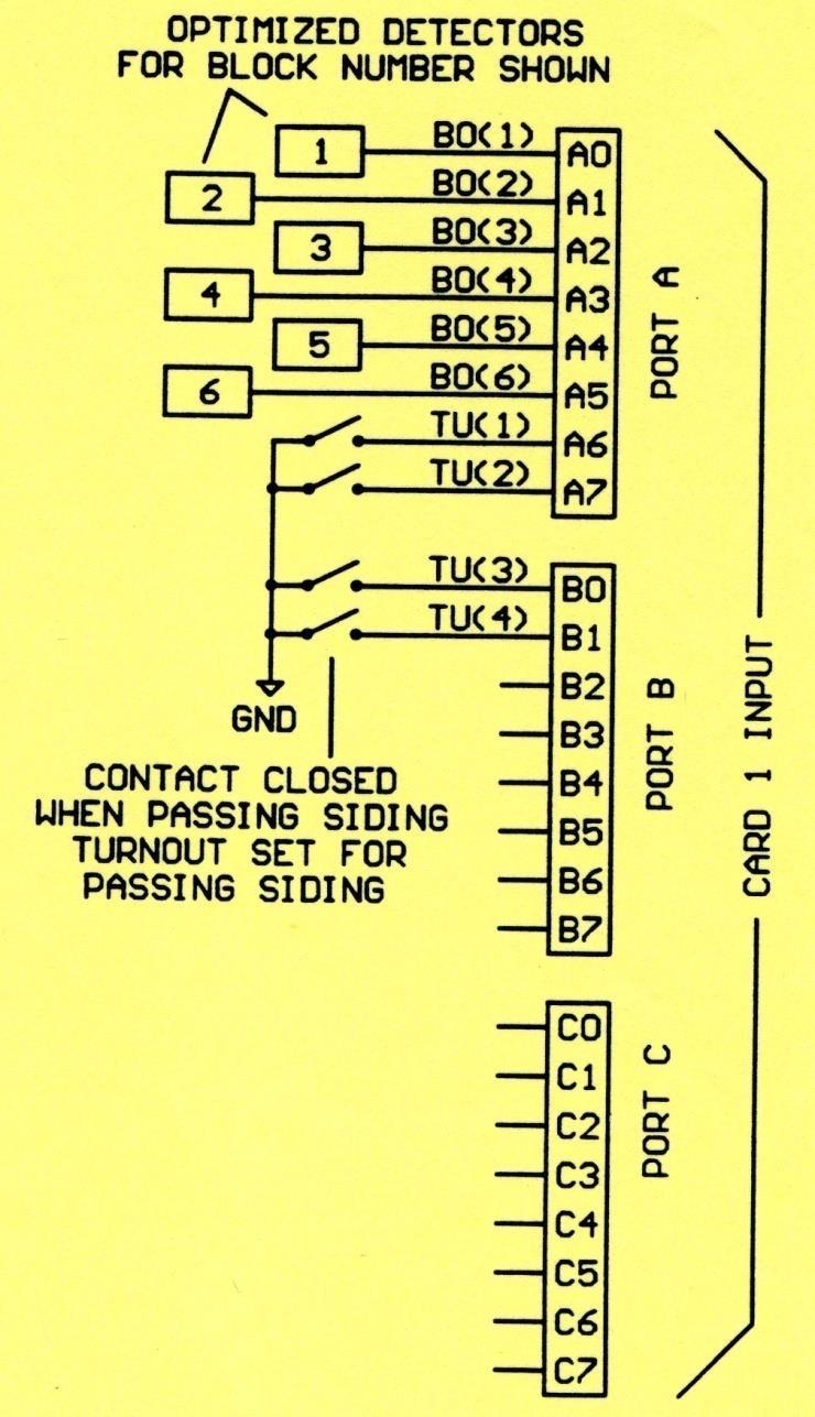
15 Each input card provides 32 added inputs 15
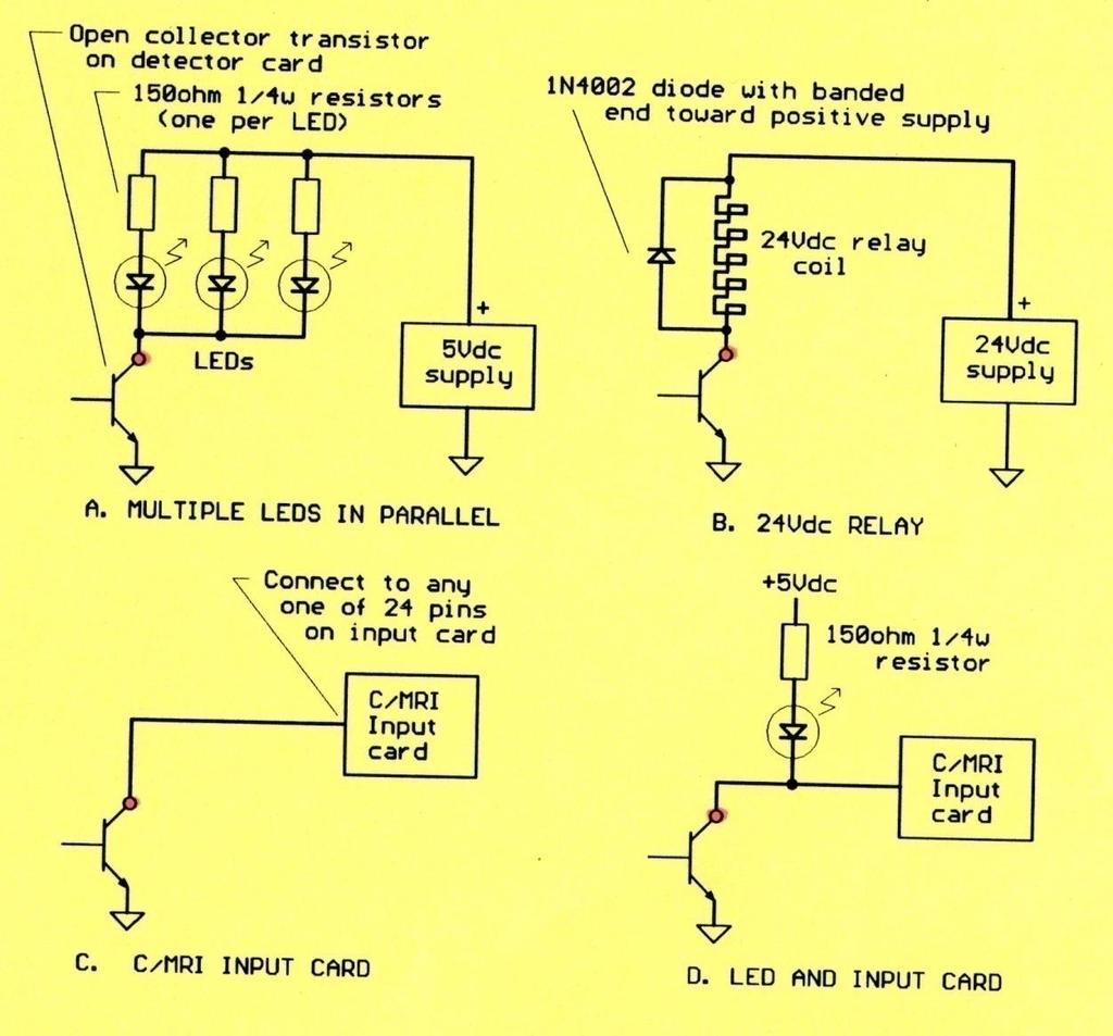
 Input grounded is a hardware logic 0 (0")
16 Handling C/MRI inputs is straightforward Input open circuited is hardware logic 1 (+5Vdc) Input grounded is a hardware logic 0 (0 volts) 16

17 Example C/MRI input connections: 17

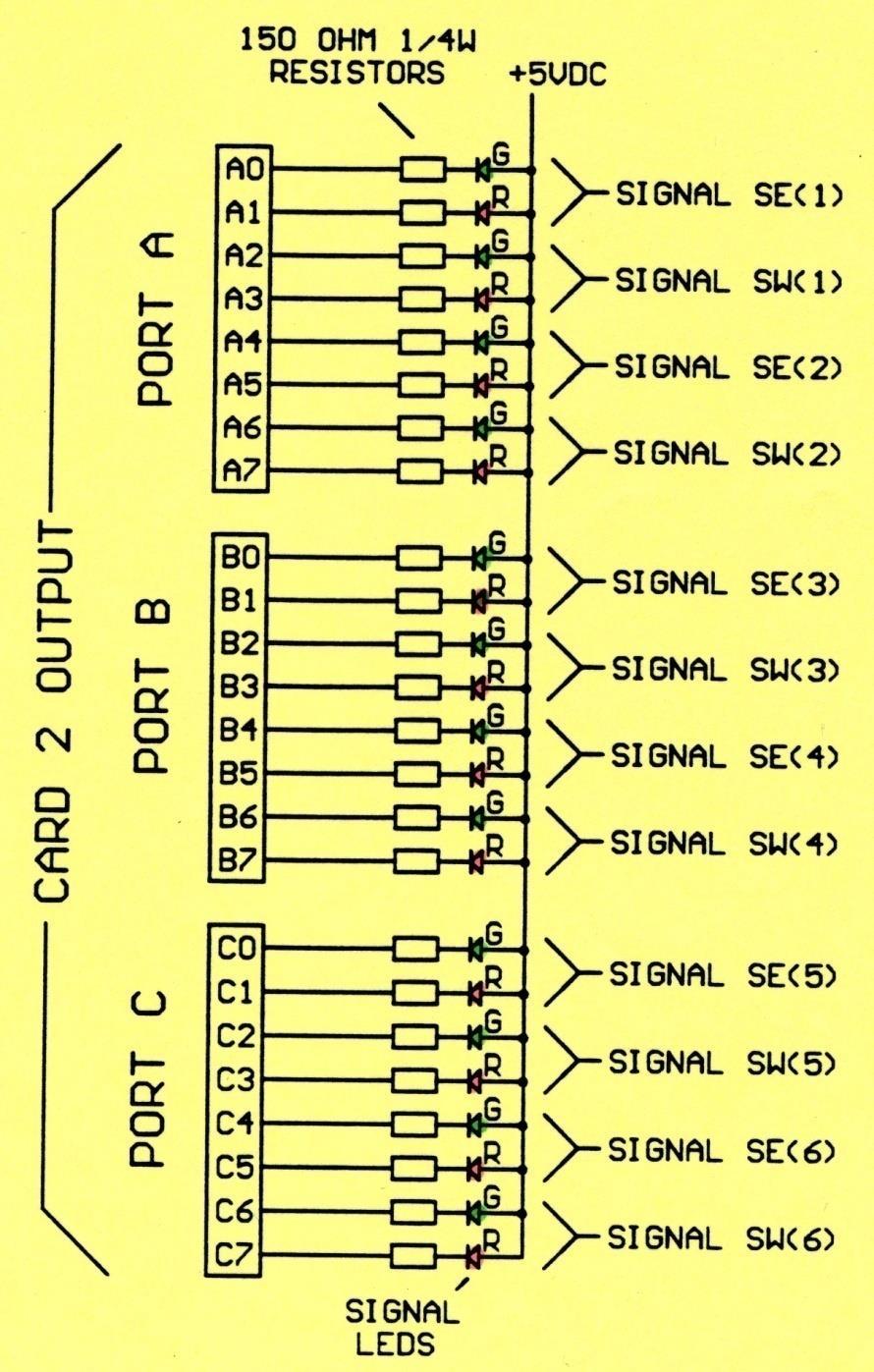
18 Each output card provides 32 added outputs 18
 Each DOUT32 provides 32 output lines (switches)")
19 Every C/MRI output can be considered to be a simple SPST toggle switch Software simple turns the toggle switch on or off When the toggle is on it is grounded Each SMINI provides 48 output lines (switches) Each DOUT32 provides 32 output lines (switches) 19

20 Drive almost any devices directly from C/MRI output line Within.3A, 40volt limit 20

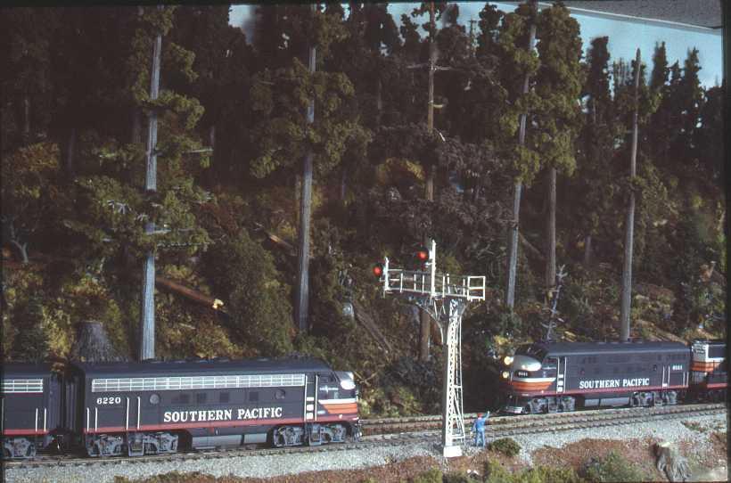
21 Each output can drive multiple devices 21

22 Programming the C/MRI is straightforward: - like using the English language: An extremely active User s Group is available to help you in every step: 22

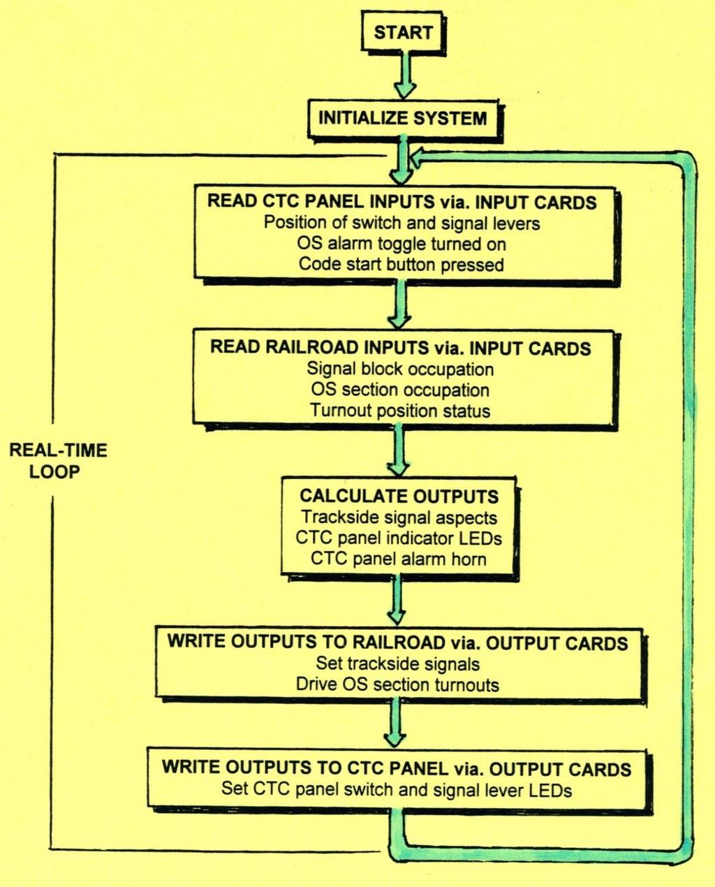
23 All C/MRI programs follow the same logic flow diagram 23
24 During this presentation we will cover: Block occupancy detection 24

25 For best possible performance: use the DCCOD for DCC railroads use the OD for DC railroads 25
26 Advantages provided by DCCOD are numerous: Transformer isolated High 150K ohm pot adjustable sensitivity Turn-on turn-off delay Monitor LED for setting sensitivity Open collector output (.3A, 40Vdc) Track current up to 20A Small modular unit for easy plug-in and system debug Priced very reasonable - $9 for medium size layout 26

27 Everything is out in the open with the C/MRI Including full schematics, parts lists and assembly instructions as well as extensive application information 27

28 A Mother Board (ODMB) is available to further simplify wiring and system debugging 28
29 29
30 During this presentation we will cover: Signaling and turnout control 30

31 Signaling can add so much interest, beauty and operational realism to a model railroad and it is so easily and cost effectively accomplished using the C/MRI 31
32 Five great reasons for using a computer to signal your railroad: 1. Simplicity 2. Flexibility 3. Prototypical fidelity 4. Easy expandability 5. Low cost (See or separate handout provided for details expanding upon each benefit) 32
33 Using the C/MRI makes prototype signaling easy to accomplish: Straightforward application Well proven technology Available as boards only, complete kits or fully assembled and tested Everything out in the open - full schematics, parts lists and abundant software Total flexibility to accomplish every need Very cost effective solutions 33
34 34
35 35

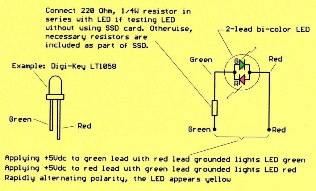
36 Light Emitting Diodes (LEDs) are basic elements to designing most signal systems 36

37 Preferred (most common) method of wiring color light signals Uses outputs configured for standard current sinking Applies when signals are wired with common anode 37

38 Driving a searchlight signal using a 3-lead bi-color LED 38
39 39
40 40

41 Two color signaling a small railroad 41
42 42
43 43
44 44

45 Three color signals with 2-headed signals leading into passing sidings In each example, C/MRI documentation leads you step-by-step through the complete interfacing project 45

46 Connecting switch motors directly to C/MRI outputs Requires 2 outputs per switch motor 46

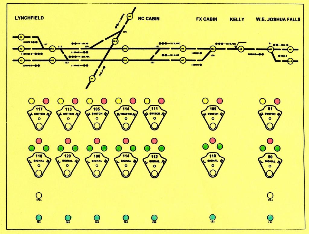
47 Alternatively, only a single output is required when incorporating an SMC12 card Also, interface cards are available for connecting to twin-coil switch machines 47

48 Easiest to implement local panel for emulating the operation of a dualcontrol power switch motor Additional options provided in Handbook include adding padlock function and using separate toggles for the Selector Lever and Hand-Throw Levers 48
49 49
50 50
51 During this presentation we will cover: Centralized Traffic Control Systems 51
52 52

53 CTC machines can be great additions to any size railroad Dirk Start using a GRS style machine modeling the C&O operating on the former PM between Holland and Grand Rapids Michigan

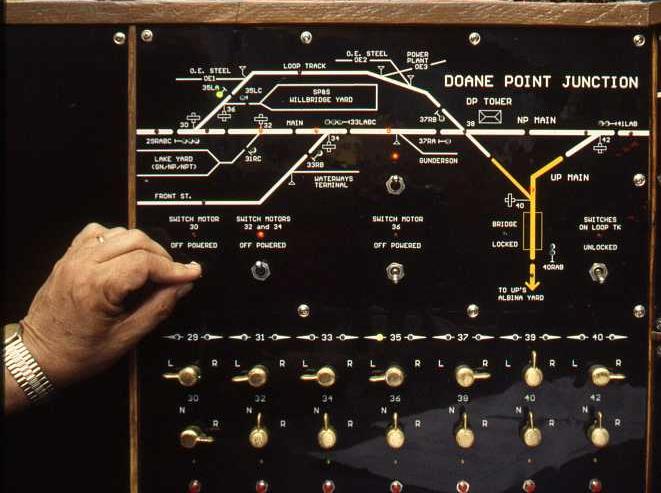
54 A small size CTC machine covering the east end of UP s Albina Yard in Portland OR on the SVOS
55 55
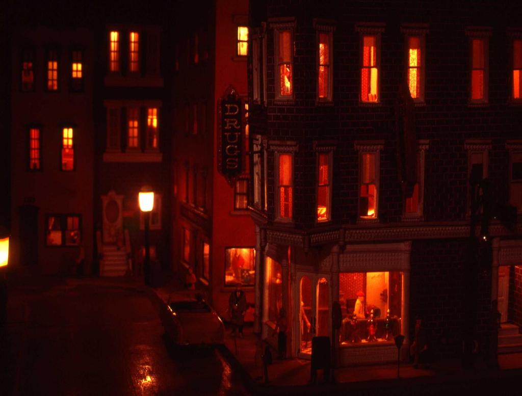
56 56

57 Wiring switch and signal levers and code button is easy with the C/MRI 57


58 Wiring the switch and signal indication lamps is just as easy 58
59 59
60 60

61 CSX Clinchfield Dispatching Center is quite applicable to a C/MRI based club size system Some C/MRI users are already interfacing to five monitors within computerized dispatching centers 61

62 Monitoring operational status is readily available by studying the graphics display 62

63 Modern dispatching with C/MRI 63
64 During this presentation we will cover: Additional applications 64

65 Automated room and scenic lighting control tied to fast clock simulating 24-hour day-night operation easily accomplished using the C/MRI 65

66 Night operation can be dramatic and including sunrise and sunset effects can be spectacular 66
67

68 New Prototypical Grade Crossing Control (PGCC) Drives gates, flashers (w/fade-in and fade-out), real grade bell digitally recorded sound and 4-prototypical bell control options and all exactly like the prototype 68

69 Automate scenic lift-up to totally eliminate duckunders 69

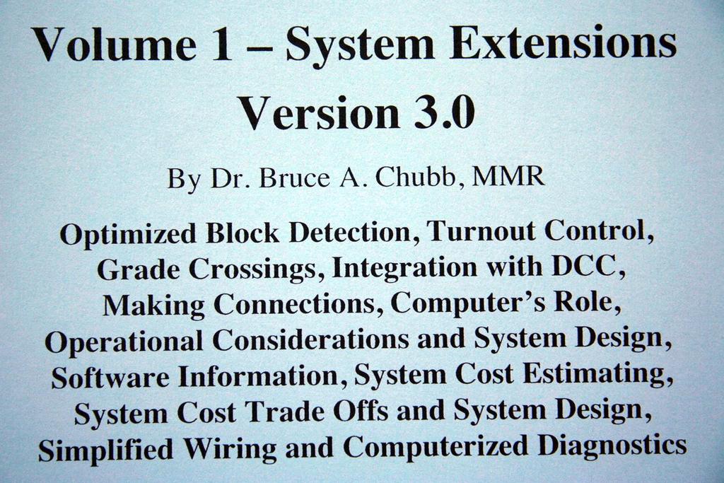
70 Two new Railroader s Applications Handbooks are availiable Together these totally replace single Volume V2.2 70
71 71
72 72
73 During this presentation we will cover: System assembly and simplified wiring 73
74 You can easily take advantage of the C/MRI Several options available: bare board from JLC Enterprises complete kits fully assembled and tested from Don Wood. 74
75 The C/MRI documentation is extremely thorough and follows a step by step everything explained process: User s Manual V3.1 Application Handbook Volume 1 Application Handbook Volume 2 75
76 76
77 77
78 78
79 79

80 80
81 81

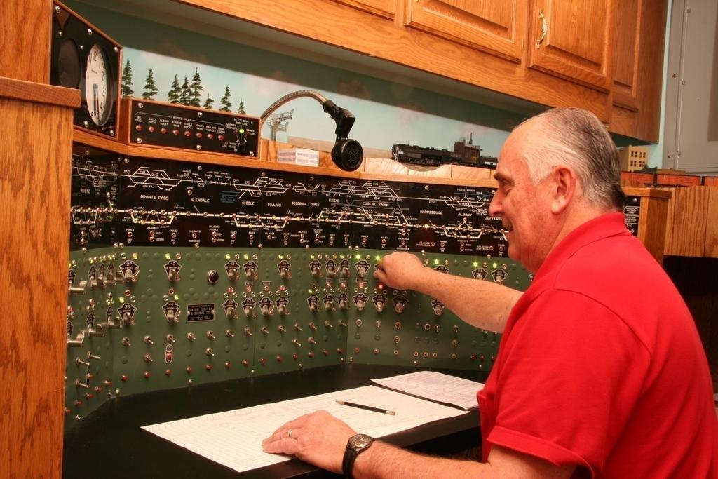
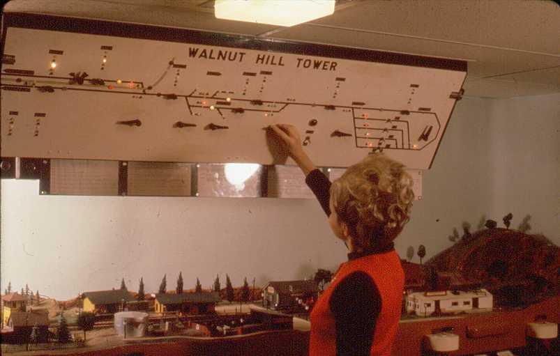
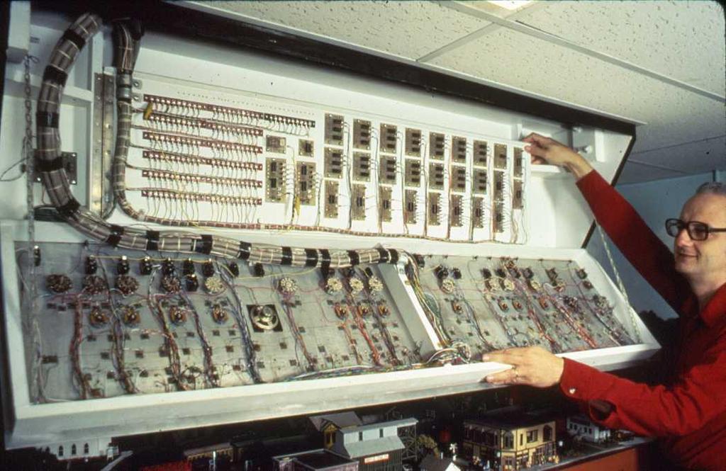
82 My CTC board. It is based on US&S type board. Each panel is 30 inches wide so the CTC is 120 inches wide. My board also includes a screen display. The screen also provides a number of trouble shooting routines. 82


83 To add in wiring and reduce the number of printed circuit boards required, I have developed two small boards that are helpful. These boards are available from me. They are bare boards but I provide a list of parts and where they can be obtained. Currently the cost is $2 for either board plus postage. The boards use the standard network CAT5/6 cable (8 wires) to help with wiring. It has an RJ45 connecter for that cable on one end and either a Molex connector or a screw terminal block on the other end. The Molex fits all the standard C/MRI boards. The Molex option and the screw terminal option. 83

84 The second board I call my Signal Control Circuit or SCC for short. It also has the CAT5/6 connector at the right and 15 screw terminals across the bottom. Also 2 screw terminals for 5+ Volts and Common connections. It allows 4 pair of wires to control a total of 12 LEDs in signals. Previously you saw a diagram of a standard OS section which had one double head three color signals and two single head three color signals. That is a total of 12 LEDs to light. Rather than use 12 outputs from a SMINI board we only need 8 outputs thus saving on boards, wire, and effort. The 12 resistors can be matched to the particular LEDs you use. Currently these boards are also $2 each plus shipping. 84
85 In summary You have seen that a computer will add a new dimension and even more enjoyment to your model railroading hobby 85

86 The C/MRI is easy to apply It is an educational project It is a fun project Include the C/MRI on your railroad I know that you will love it! 86
87 I would like to thanks a number of people who have been helpful with my understanding of C/MRI, with the building of the 100+ printed circuit boards, wiring my CTC panel, creating over 5,000 lines of Visual Basic 6.0 code, running several thousand feet of wire, and building almost 100 temporary signals that we are using till I have time to build detailed PB&JRY and PRR signals. They are: Bill Carr, Gail Carr, Bruce Chubb, Jim Withrow, Don Wood, and the members of the C/MRI Users Yahoo Group. A question and answer session will conclude my presentation. 87
88 THANK YOU For Attending C/MRI 101- The Basics By Jay Beckham Visit our layout: Sunday Noon to 6:00 88
Signaling with CATS & JMRI
 Signaling with CATS & JMRI Dick Johannes & the HUB Division Signal Committee May 2016 5/15/2016 1 The HUB Division Signal Committee Members 5/15/2016 2 Hoosac, Upton & Boston RR Now over 65 members Dick
Layout Design For Signaling
 Layout Design For Signaling 2 0 1 5, Ro d n e y B l a c k N o v e m b e r 1 5, 2 0 1 5 11/15/2015 1 Download This Presentation 11/15/2015 Layout Design for Signaling 2 Outline 1. Why Signal a Layout 2.
Layout Design For Signaling
 Layout Design For Signaling 2014, Rodney Black h t t p : / / h o m e.c o mca st.n e t / ~ kb 0o ys June 29, 2014 7/5/2014 1 Download 7/5/2014 Layout Design for Signaling 2 Outline 1. Why Signal a Layout
Azatrax Model Railroad Track Signal Control - Single Track
 Installation Guide Azatrax Model Railroad Track Signal Control - Single Track TS2 What it is: The TS2 operates one or two trackside block signals (one in each direction) on one track to simulate the block
Simplified Signaling for Modelers
 Simplified Signaling for Modelers Rule 281 Clear 1 Author: Gary Evans North Central Region, Division 3 garytrain47@frontier.com Revision: May 05, 2014 Handout: NORAC Signal Aspects Sheet 2 Introduction
Introduction to Layout Control with JMRI/PanelPro. Create a Detailed CTC Machine Model with JMRI/PanelPro
 Add Signals to your Layout with JMRI/PanelPro Dick Bronson - R R -C irk its, I n c. Other Clinics in this series: Introduction to Layout Control with JMRI/PanelPro 8:30 PM, Sunday, July 13th Create a Detailed
Signal Logic Example
 CPL Example Signal Logic Example Block Detect Occupancy Mast Turnout Position Norm/Rev Next From Next Signal Logic Rules Rule to Aspect This Appearance Lamps Effects To previous Signal Drivers With the
HUB CATS File Development Documentation
 I. Terminology HUB CATS File Development Documentation Recommended Practices for Computer-Aided Track Signal (CATS) File Development Version 3.0 February 14, 2015 1. Active Module is a module that has
SIGNALING PRACTICES ON PROTOTYPE AND MODEL RAILROADS
 SIGNALING PRACTICES ON PROTOTYPE AND MODEL RAILROADS Bill Ataras September 30, 2013 PROTOTYPE SIGNALING PRACTICE 1. Many different types of signals A. Block signals B. Interlocking signals C. Whistles
Scale Track System. 21 Century y Signal System 2-Rail Manual
 Scale Track System st 21 Century y Signal System 2-Rail Manual TABLE OF CONTENTS Introduction...2-3 Road Signal Board Diagram and Definitions...4-6 Tips for Handling the Circuit Board...6 2-Rail Detector
ENGR 1000, Introduction to Engineering Design
 ENGR 1000, Introduction to Engineering Design Unit 2: Data Acquisition and Control Technology Lesson 2.4: Programming Digital Ports Hardware: 12 VDC power supply Several lengths of wire NI-USB 6008 Device
NMRA 2013 Peachtree Express Control Panel Editor - B
 NMRA 2013 Peachtree Express Control Panel Editor - B Dick Bronson RR-CirKits, Inc. JMRI Control Panel Editor for Automatic Train Running Using Warrants Items Portal Table The 'Portal Table' is part of
Signalist SC1. DCC signal controller user manual Covers configuration for UK signals
 Signalist SC1 DCC signal controller user manual Covers configuration for UK signals 1 Contents Overview... 3 Connections... 3 Ribbon cable connection... 3 DCC track connection... 5 2-aspect signal connections...
"Sophisticated Model Railroad Electronics"
 LOGIC RAIL TM "Sophisticated Model Railroad Electronics" TECHNOLOGIES 21175 Tomball Pkwy Phone: (281) 251-5813 Suite 287 email: info@logicrailtech.com Houston, TX 77070 http://www.logicrailtech.com Block
MSS-CASCADE User Manual
 MSS-CASCADE User Manual Overview The MSS-CASCADE module is designed to provide basic ABS signaling functionality at a block boundary as part of a Modular Signal System implementation ( http://modularsignalsystem.info/
MRC DISPATCHER TRACKSIDE DECODER
 MRC DISPATCHER TRACKSIDE DECODER (Item AD360) Congratulations!! You have just purchased an advanced DCC accessory decoder. Combined with the MRC PRODIGY DCC system or any manufacturer s DCC system, the
Introduction to Aspect Signaling with JMRI/PanelPro
 Introduction to Aspect Signaling with JMRI/PanelPro Dick Bronson - RR CirKits, Inc. Clinics in this series: Introduction to Aspect Signaling with JMRI/PanelPro 4:00 PM, Wednesday, July 6th Aspect Based
DNA-STP-SYNC Synchronization and Screw Terminal Panel. User Manual
 DNA-STP-SYNC Synchronization and Screw Terminal Panel User Manual Accessory Panel for PowerDNA Cube (DNA) Systems February 2009 Edition PN Man-DNA-STP-SYNC-0209 Version 1.2 Copyright 1998-2009 All rights
Lesson Sequence: S4A (Scratch for Arduino)
") Lesson Sequence: S4A (Scratch for Arduino) Rationale: STE(A)M education (STEM with the added Arts element) brings together strands of curriculum with a logical integration. The inclusion of CODING in STE(A)M
Lesson Sequence: S4A (Scratch for Arduino) Rationale: STE(A)M education (STEM with the added Arts element) brings together strands of curriculum with a logical integration. The inclusion of CODING in STE(A)M
Light-It Decoder p/n Lighting decoder w/built-in white LED
 Description of configuration variables (CVs) The factory default value is in parenthesis after the description Decoder Reset CV CV128 Setting this CV to a value of 170 will reset the decoder to factory
DM1624, DM1612, DM812
 Installation Guide Hardware and Software DM Series Digital Processors models DM1624, DM1612, DM812 LECTROSONICS, INC. 1 Installation Specific Information Only This guide covers only installation related
Dish Diversity Switch
 www.travel-vision.com Dish Diversity Switch INSTALLATION & USER S MANUAL Version 3.1 October 2013 PREFACE The information in this Installation and User s Manual is subject to change in order to improve
INSTALLATION AND OPERATION INSTRUCTIONS EVOLUTION VIDEO DISTRIBUTION SYSTEM
 INSTALLATION AND OPERATION INSTRUCTIONS EVOLUTION VIDEO DISTRIBUTION SYSTEM ATTENTION: READ THE ENTIRE INSTRUCTION SHEET BEFORE STARTING THE INSTALLATION PROCESS. WARNING! Do not begin to install your
ENGR 1000, Introduction to Engineering Design
 Unit 2: Mechatronics ENGR 1000, Introduction to Engineering Design Lesson 2.3: Controlling Independent Systems Hardware: 12 VDC power supply Several lengths of wire NI-USB 6008 Device with USB cable Digital
Combo Board.
 Combo Board www.matrixtsl.com EB083 Contents About This Document 2 General Information 3 Board Layout 4 Testing This Product 5 Circuit Diagram 6 Liquid Crystal Display 7 Sensors 9 Circuit Diagram 10 About
Bill of Materials: Super Simple Water Level Control PART NO
 Super Simple Water Level Control PART NO. 2169109 Design a simple water controller in which electrodes are required to sense high and low water levels in a tank. Whenever the water level falls below the
Sentinel I24 Digital Input and Output Configuration
 Application Bulletin: #155 Date: October 19, 2007 Sentinel I24 Digital Input and Output Configuration The Sentinel I24 can communicate with external hardware using digital inputs and outputs. There are
EE 367 Lab Part 1: Sequential Logic
 EE367: Introduction to Microprocessors Section 1.0 EE 367 Lab Part 1: Sequential Logic Contents 1 Preface 1 1.1 Things you need to do before arriving in the Laboratory............... 2 1.2 Summary of material
Push Button Control for a Hidden Reverse Loop and Staging Area
 Push Button Control for a Hidden Reverse Loop and Staging Area With off the shelf components! Presented by Chuck Thomas NMRA Metro-North Division, Northeast Region November 14, 2015 chuckthomas350@gmail.com
Instruction Manual. Series 3000 Model R-165A. Audio/Video IF/RF Relay Panel. CATV Switching and Control
 Series 3000 Model R-165A Audio/Video IF/RF Relay Panel Instruction Manual CATV Switching and Control 585-765-2254 fax 585-765-9330 100 Housel Ave. Lyndonville NY 14098 www.monroe-electronics.com Table
AES-402 Automatic Digital Audio Switcher/DA/Digital to Analog Converter
 Broadcast Devices, Inc. AES-402 Automatic Digital Audio Switcher/DA/Digital to Analog Converter Technical Reference Manual Broadcast Devices, Inc. Tel. (914) 737-5032 Fax. (914) 736-6916 World Wide Web:
Design and Realization of the Guitar Tuner Using MyRIO
 Journal of Automation and Control, 2017, Vol. 5, No. 2, 41-45 Available online at http://pubs.sciepub.com/automation/5/2/2 Science and Education Publishing DOI:10.12691/automation-5-2-2 Design and Realization
Model Railway Animation: Part 1, LEDs - Expanded By David King
 Model Railway Animation: Part 1, LEDs - Expanded By David King By now you are most likely ready to proceed past the simple Blink sketch so that is what we will do now. A couple of simple sketches we can
LAUREL ELECTRONICS, INC.
 LAUREL ELECTRONICS, INC. Laureate Digital Panel Meter for Process, Strain & Potentiometer Follower Signals Features Selectable ±0.2, ±2, ±20, ±200, ±300 & ±600 Vdc voltage ranges Selectable ±2, ±20, ±200
MRC Prodigy Advance 2. User s Manual
 MRC Prodigy Advance 2 User s Manual T A B L E O F C O N T E N T S 1 Getting Started Introduction... 1-1 DCC Basic Background... 1-1 Specifications and Features... 1-2 System Menu Summary Chart... 1-2 2
Manual Version Audio/Video Switchers. AV4x1P AV8x1P AV8x1A
 AV4x1P AV8x1P AV8x1A Audio/Video Switchers Manual Version 2.01 BURST ELECTRONICS INC ALBUQUERQUE, NM 87109 USA (505) 898-1455 VOICE (505) 890-8926 TECH SUPPORT Made in USA (505) 898-0159 FAX www.burstelectronics.com
Single sensor setup with NIVEL210
 Single sensor setup with NIVEL210 Essential Items: 576 198 NIVEL210 RS232 748 335 Cable, Lemo 0 power supply cable Lemo 1 802 902 Cable, Lemo 0 722 409 Power supply plus power cords 802 902 576 198 748
1993 Specifications CSJ , etc. SPECIAL SPECIFICATION ITEM CCTV Central Equipment
 1993 Specifications CSJ 0922-33-042, etc. SPECIAL SPECIFICATION ITEM 8549 CCTV Central Equipment 1. Description. This Item shall govern for the furnishing and installation of closed circuit television
Booya16 SDR Datasheet
 Booya16 SDR Radio Receiver Description The Booya16 SDR radio receiver samples RF signals at 16MHz with 14 bits and streams the sampled signal into PC memory continuously in real time. The Booya software
POINTS POSITION INDICATOR PPI4
 POINTS POSITION INDICATOR PPI4 Monitors the brief positive operating voltage across points motors when they are switched Lights a corresponding led on a control panel to show the last operation of each
8 PIN PIC PROGRAMMABLE BOARD (DEVELOPMENT BOARD & PROJECT BOARD)
") ESSENTIAL INFORMATION BUILD INSTRUCTIONS CHECKING YOUR PCB & FAULT-FINDING MECHANICAL DETAILS HOW THE KIT WORKS LEARN ABOUT PROGRAMMING WITH THIS 8 PIN PIC PROGRAMMABLE BOARD (DEVELOPMENT BOARD & PROJECT
ESSENTIAL INFORMATION BUILD INSTRUCTIONS CHECKING YOUR PCB & FAULT-FINDING MECHANICAL DETAILS HOW THE KIT WORKS LEARN ABOUT PROGRAMMING WITH THIS 8 PIN PIC PROGRAMMABLE BOARD (DEVELOPMENT BOARD & PROJECT
LEVEL CROSSING MODULE FOR LED SIGNALS LCS2
 LEVEL CROSSING MODULE FOR LED SIGNALS LCS2 Fully Flexible Controller for Common-Anode LED signals Automatically detects trains using an infra-red sensor mounted below the track bed Operates attached yellow
Vorne Industries. 87/719 Analog Input Module User's Manual Industrial Drive Itasca, IL (630) Telefax (630)
 Telefax (630)") Vorne Industries 87/719 Analog Input Module User's Manual 1445 Industrial Drive Itasca, IL 60143-1849 (630) 875-3600 Telefax (630) 875-3609 . 3 Chapter 1 Introduction... 1.1 Accessing Wiring Connections
Vorne Industries 87/719 Analog Input Module User's Manual 1445 Industrial Drive Itasca, IL 60143-1849 (630) 875-3600 Telefax (630) 875-3609 . 3 Chapter 1 Introduction... 1.1 Accessing Wiring Connections
AES-404 Digital Audio Switcher/DA/Digital to Analog Converter
 Broadcast Devices, Inc. AES-404 Digital Audio Switcher/DA/Digital to Analog Converter Technical Reference Manual Broadcast Devices, Inc. Tel. (914) 737-5032 Fax. (914) 736-6916 World Wide Web: www.broadcast-devices.com
CAT EXT-CAT USER MANUAL
 CAT5 8000 EXT-CAT5-8000 USER MANUAL www.gefen.com ASKING FOR ASSISTANCE Technical Support: Telephone (818) 772-9100 (800) 545-6900 Fax (818) 772-9120 Technical Support Hours: 8:00 AM to 5:00 PM Monday
LAUREL. Laureate Digital Panel Meter for Load Cell & Microvolt Input ELECTRONICS, INC. Features. Description
 Description LAUREL ELECTRONICS, INC. Features Laureate Digital Panel Meter for Load Cell & Microvolt Input 20, 50, 100, 250 & 500 mv ranges Span adjust from 0 to ±99,999, zero adjust from -99,999 to +99,999
LinTronic. TableTop series. Hardware version 6. Updated
 Updated 151120 TableTop series Hardware version 6 We keep expanding Hardware 6 Introduced 2011 Hardware 5 Introduced 2006 Hardware 4 Introduced 2003 32KByte 128KByte 256KByte What's new? Feature Hardware
Transportation Engineering - II Dr. Rajat Rastogi Department of Civil Engineering Indian Institute of Technology - Roorkee
 Transportation Engineering - II Dr. Rajat Rastogi Department of Civil Engineering Indian Institute of Technology - Roorkee Lecture 25 Interlocking of Track Dear students, welcome you back to the lecture
"Sophisticated Model Railroad Electronics"
 LOGIC RAIL TM "Sophisticated Model Railroad Electronics" TECHNOLOGIES 21175 Tomball Pkwy Phone: (281) 251-5813 Suite 287 email: info@logicrailtech.com Houston, TX 77070 http://www.logicrailtech.com Block
Scanned and edited by Michael Holley Nov 28, 2004 Southwest Technical Products Corporation Document Circa 1976
 GT-6144 Graphics Terminal Kit The GT-6144 Graphics Terminal Kit is a low cost graphics display unit designed to display 96 lines of 64 small rectangles per line on a standard video monitor or a slightly
Foreword: The purpose of this document is to describe how to install and configure Neets 4 relay box
 Foreword: The purpose of this document is to describe how to install and configure Neets 4 relay box COPYRIGHT All information contained in this manual is the intellectual property of and copyrighted material
BLOCK OCCUPANCY DETECTOR
 BLOCK OCCUPANCY DETECTOR This Block Occupancy Detector recognises the current drawn by moving trains within a block, and can operate a number of built-in programs in response. When used with DC systems,
Palestine Technical College. Engineering Professions Department. EEE Digital Logic Fundamentals. Experiment 2.
 Palestine Technical ollege Engineering Professions epartment EEE - Experiment ode onverters # Student No Name Surname Sign Fall 07-0 EEE Objectives: uild a Gray code to binary converter. Use design steps
Yosemite in HO FROM HALFDOME TO CAMP CURRY
 Yosemite in HO FROM HALFDOME TO CAMP CURRY Don Evans 6x9 layout 07/11/2008 What is it? This document describes a 6-foot by 9-foot HO scale model railroad layout, created in the single car garage walled
Direct PWM. 1000/2000 Series POWERBLOK MODULE
 Direct PWM 1000/2000 Series POWERBLOK MODULE Features A universal servo-drive integrated on a Power Hybrid Module. Designed for direct PWM Servo Control Designed for use with Deta Tau's PMAC controllers
DX-10 tm Digital Interface User s Guide
 DX-10 tm Digital Interface User s Guide GPIO Communications Revision B Copyright Component Engineering, All Rights Reserved Table of Contents Foreword... 2 Introduction... 3 What s in the Box... 3 What
Altera s Max+plus II Tutorial
 Altera s Max+plus II Tutorial Written by Kris Schindler To accompany Digital Principles and Design (by Donald D. Givone) 8/30/02 1 About Max+plus II Altera s Max+plus II is a powerful simulation package
ex 800 Series ematrix System
 Protecting Your Human Assets During Emergency ex 800 Series ematrix System The ex 800 Series ematrix System is a fully integrated and versatile public address system which is designed distinctively to
DH163D Fits Many HO Locomotives
 DH163D Fits Many HO Locomotives Complete Train Control Run Your Trains, Not Your Track! HO Scale Mobile Decoder Digitrax Easy Connect 9 Pin Harness 1.5 Amp/2 Amp Peak 6 FX 3 Functions, 0.5 Amp Features:
PRODUCT MANUAL. Product Description. Waterproof 4 Channel DMX to RGB-W LED Controller
 4 Channel to RGB-W LED Controller Waterproof 4 Channel to RGB-W LED Controller Product Description Thank you for purchasing Solid Apollos Waterproof 4 Channel to RGBW LED Controller. It is a new standard
How To Build Megavolt s Small Buffered JTAG v1.2
 How To Build Megavolt s Small Buffered JTAG v1.2 Abstract A JTAG cable should be considered mandatory equipment for any serious tester. It provides a means to backup the information in the receiver and
The Serial Port is Dead! Long Live the Serial Port! USB Serial Port Breadboard Experiments with the FTDI FT232R
 The Serial Port is Dead! Long Live the Serial Port! USB Serial Port Breadboard Experiments with the FTDI FT232R Copyright Joe Pardue 2008. This material was previously published in the June 2008 issue
DMC550 Technical Reference
 DMC550 Technical Reference 2002 DSP Development Systems DMC550 Technical Reference 504815-0001 Rev. B September 2002 SPECTRUM DIGITAL, INC. 12502 Exchange Drive, Suite 440 Stafford, TX. 77477 Tel: 281.494.4505
Multi-Zone Programmable RGB ColorPlus LED Touch Controller (Remote Control) and RGB ColorPlus LED Touch Controller (Receiver)
 and RGB ColorPlus LED Touch Controller (Receiver)") 11235 West Bernardo Court, Suite 102 San Diego, CA 92127 888-880-1880 Fax: 707-281-0567 EnvironmentalLights.com Multi-Zone Programmable RGB ColorPlus LED Touch Controller (Remote Control) and RGB ColorPlus
11235 West Bernardo Court, Suite 102 San Diego, CA 92127 888-880-1880 Fax: 707-281-0567 EnvironmentalLights.com Multi-Zone Programmable RGB ColorPlus LED Touch Controller (Remote Control) and RGB ColorPlus
NX APPLICATION NOTE Led Guided Assembly Connector Pinning with Continuity
 NX APPLICATION NOTE Led Guided Assembly Connector Pinning with Continuity Background Many wire harness connectors are designed to use a push-click-pull method of wire insertion. This method requires the
Analog Output for the TSI DUSTTRAK Aerosol Monitor Model 8520
 Exposure Monitoring Analog Output for the TSI DUSTTRAK Aerosol Monitor Model 8520 Application Note ITI-073 Introduction Newer models of the DUSTTRAK Model 8520 are capable of providing an analog output
A Motor can be in many groups, by assigning additional channel# on it.
 Timer Remote Control Instruction How to use the channel numbers - There are 32 channels on the Remote Control Timer you can assign to Curtain Motor(s). To operate the Motors individually by itself only,
Operating Instructions for Throttle Valves Using VRC Valve Positioner
 ThrottleMaster TM Operating Instructions for Throttle Valves Using VRC Valve Positioner p/n: X709116 $10.00 3/2012 Throttlemaster is a registered trademark of Vacuum Research Corporation Introduction The
LED Array Board.
 LED Array Board www.matrixtsl.com EB087 Contents About This Document 2 General Information 3 Board Layout 4 Testing This Product 5 Circuit Description 6 Circuit Diagram 7 About This Document This document
ENGR 40M Project 3a: Building an LED Cube
 ENGR 40M Project 3a: Building an LED Cube Lab due before your section, October 31 November 3 1 Introduction In this lab, you ll build a cube of light-emitting diodes (LEDs). The cube is wired to an Arduino,
DZ143. Z Scale. Mobile Decoder 1.25 Amp/2 Amp Peak 4 FX 3 Functions, 0.5 Amp. Fits Many Z, N and HO Scale Locomotives
 Digitrax Command Control Run Your Trains, Not Your Track! DZ143 Fits Many Z, N and HO Scale Locomotives Z Scale Mobile Decoder 1.25 Amp/2 Amp Peak 4 FX 3 Functions, 0.5 Amp Features: Digitrax LocoMotion
A3524-4x4 HDMI MATRIX SWITCHER / SPLITTER Via Cat5e with IR Extenders USER MANUAL. Table of Contents
 A3524-4x4 MATRIX SWITCHER / SPLITTER Via Cat5e with IR Extenders USER MANUAL Table of Contents 1.0 Introduction...2 2.0 Panel Descriptions...3 3.0 Connection and Operation.......3 4.0 Connection Diagram...6
APPLICATION NOTE 4312 Getting Started with DeepCover Secure Microcontroller (MAXQ1850) EV KIT and the CrossWorks Compiler for the MAXQ30
 EV KIT and the CrossWorks Compiler for the MAXQ30") Maxim > Design Support > Technical Documents > Application Notes > Microcontrollers > APP 4312 Keywords: MAXQ1850, MAXQ1103, DS5250, DS5002, microcontroller, secure microcontroller, uc, DES, 3DES, RSA,
Maxim > Design Support > Technical Documents > Application Notes > Microcontrollers > APP 4312 Keywords: MAXQ1850, MAXQ1103, DS5250, DS5002, microcontroller, secure microcontroller, uc, DES, 3DES, RSA,
Automation Interface Requirements for J602 Basic I/O Interface of a DPC 4 Welding System
 - 1 - Automation Interface Requirements for J602 Basic I/O Interface of a DPC 4 Welding System The DPC 4 welding system offers several features that are intended to communicate with automation. These features
AZ DISPLAYS, INC. COMPLETE LCD SOLUTIONS SPECIFICATIONS FOR 15.0 OPEN FRAME MONITOR
 AZ DISPLAYS, INC. COMPLETE LCD SOLUTIONS SPECIFICATIONS FOR 15.0 OPEN FRAME MONITOR PART NUMBER: AOM150X03 SERIES DATE: SEPT 04, 2008 1. Introduction: 1.1 About the Product AOM150Xxx 15.0 Open Frame Monitor
LMH0340/LMH0341 SerDes EVK User Guide
 LMH0340/LMH0341 SerDes EVK User Guide July 1, 2008 Version 1.05 1 1... Overview 3 2... Evaluation Kit (SD3GXLEVK) Contents 3 3... Hardware Setup 4 3.1 ALP100 BOARD (MAIN BOARD) DESCRIPTION 5 3.2 SD340EVK
ENGR 40M Project 3b: Programming the LED cube
 ENGR 40M Project 3b: Programming the LED cube Prelab due 24 hours before your section, May 7 10 Lab due before your section, May 15 18 1 Introduction Our goal in this week s lab is to put in place the
Complete Train Control. Run Your Trains, Not Your Track!
 DH166PS Fits Many DCC-Ready HO Locomotives.672 x 1.074 x.259 17.08mm x 27.28mm x 6.6mm Features: FX3 Function outputs for prototypical lighting effects and on/off control: Digitrax Complete Train Control
16 Stage Bi-Directional LED Sequencer
 16 Stage Bi-Directional LED Sequencer The bi-directional sequencer uses a 4 bit binary up/down counter (CD4516) and two "1 of 8 line decoders" (74HC138 or 74HCT138) to generate the popular "Night Rider"
NORTHWESTERN UNIVERSITY TECHNOLOGICAL INSTITUTE
 NORTHWESTERN UNIVERSITY TECHNOLOGICL INSTITUTE ECE 270 Experiment #8 DIGITL CIRCUITS Prelab 1. Draw the truth table for the S-R Flip-Flop as shown in the textbook. Draw the truth table for Figure 7. 2.
GAUGEMASTER PRODIGY EXPRESS
 GAUGEMASTER PRODIGY EXPRESS DCC01 USER MANUAL Version 1.2 2014 1 T A B L E O F C O N T E N T S 1 Getting Started Introduction Specifications and Features Quick Start Connecting to Your Layout Running a
Personal Information Page
 Rev. 08.29.07 Personal Information Page Installing Dealer Name Date of Installation Day Month Year Type of System Executive MD500 MD1000.2 MHDTV MD5Slim MSD60 Freedom (not recommended) Serial Number of
This Errata Sheet contains corrections or changes made after the publication of this manual.
 Errata Sheet This Errata Sheet contains corrections or changes made after the publication of this manual. Product Family: DL205 / DL305 Manual Number D2-DCM Revision and Date 2nd Edition; February 2003
Laboratory 11. Required Components: Objectives. Introduction. Digital Displays and Logic (modified from lab text by Alciatore)
") Laboratory 11 Digital Displays and Logic (modified from lab text by Alciatore) Required Components: 2x lk resistors 1x 10M resistor 3x 0.1 F capacitor 1x 555 timer 1x 7490 decade counter 1x 7447 BCD to
Laboratory 11 Digital Displays and Logic (modified from lab text by Alciatore) Required Components: 2x lk resistors 1x 10M resistor 3x 0.1 F capacitor 1x 555 timer 1x 7490 decade counter 1x 7447 BCD to
DT9834 Series High-Performance Multifunction USB Data Acquisition Modules
 DT9834 Series High-Performance Multifunction USB Data Acquisition Modules DT9834 Series High Performance, Multifunction USB DAQ Key Features: Simultaneous subsystem operation on up to 32 analog input channels,
Pricelist No. 1/2017 (Validity from 1. February 2017)
") Kleiner Ring 9 D-25492 Heist/Germany Phone: 0049 4122 / 977 381 Fax: Pricelist No. 1/2017 (Validity from 1. February 2017) Order code Description Price per item in incl. German VAT. 4-fold turnout decoder
Kleiner Ring 9 D-25492 Heist/Germany Phone: 0049 4122 / 977 381 Fax: Pricelist No. 1/2017 (Validity from 1. February 2017) Order code Description Price per item in incl. German VAT. 4-fold turnout decoder
AES Channel Digital/Analog Audio Switcher/DA/Digital to Analog Converter
 Broadcast Devices, Inc. AES-408 8 Channel Digital/Analog Audio Switcher/DA/Digital to Analog Converter Technical Reference Manual Broadcast Devices, Inc. Tel. (914) 737-5032 Fax. (914) 736-6916 World Wide
Turnout Decoder TD Maxi. User Manual - version 0.1.6
 Turnout Decoder TD Maxi - version by Copyright 2013 Tehnologistic SRL All rights reserved No part of this publication may be reproduced or transmitted in any form or by any means, electronic or mechanical,
The Haply Development Kit
 The Haply Development Kit Introduction The Haply development kit is a robust and adaptable open-source hardware development platform for haptic applications. Designed to be accessible to novices and experts
Data Acquisition Using LabVIEW
 Experiment-0 Data Acquisition Using LabVIEW Introduction The objectives of this experiment are to become acquainted with using computer-conrolled instrumentation for data acquisition. LabVIEW, a program
VIDEO GRABBER. DisplayPort. User Manual
 VIDEO GRABBER DisplayPort User Manual Version Date Description Author 1.0 2016.03.02 New document MM 1.1 2016.11.02 Revised to match 1.5 device firmware version MM 1.2 2019.11.28 Drawings changes MM 2
DVI DL Super Booster Plus EXT-DVI-141DLBP. User Manual
 DVI DL Super Booster Plus EXT-DVI-141DLBP User Manual Congratulations on your purchase of the DVI DL Super Booster Plus. Your complete satisfaction is very important to us. Gefen Gefen delivers innovative,
DVI 2000HD USER MANUAL.
 DVI2000HD USER MANUAL www.gefen.com Technical Support: Telephone (818) 772-9100 (800) 545-6900 Fax (818) 772-9120 Technical Support Hours: 8:00 AM to 5:00 PM Monday thru Friday. Write To: Gefen Inc. c/o
EdgeConnect Module Quick Start Guide ITERIS INNOVATION FOR BETTER MOBILITY
 EdgeConnect Module Quick Start Guide ITERIS INNOVATION FOR BETTER MOBILITY 493456301 Rev B April 2009 Table of Contents Installation... 1 Setup... 2 Operation... 4 Live Video... 4 Video Settings... 5 Network
Controller, Scheduler-Timer Model UCS-01 version User Guide
 Model UCS-01 version 1.48+ User Guide QUICK REFERENCE GUIDE Time Date IDLE SCREEN 03:50PM [RUN] 05/09/06 Tue Day of the Week Schedule Mode (change via 'Set Time') [OFF] = No Events Operate [RUN] = Run
Seth h N eu N mann 1
 Seth Neumann sneumann@pacbell.net 1 Why Control Panels? Panels work well where you have a group of related indicators and controls close together Panels may not be the right answer for all fascia controls:
VNS2200 Amplifier & Controller Installation Guide
 VNS2200 Amplifier & Controller Installation Guide VNS2200 Amplifier & Controller Installation 1. Determine the installation location for the VNS2200 device. Consider the following when determining the
Auxiliary states devices
 22 Auxiliary states devices When sampling using multiple frame states, Signal can control external devices such as stimulators in addition to switching the 1401 outputs. This is achieved by using auxiliary
TV Character Generator
 TV Character Generator TV CHARACTER GENERATOR There are many ways to show the results of a microcontroller process in a visual manner, ranging from very simple and cheap, such as lighting an LED, to much
USER GUIDE. DM Engineering Multi Station Relay Adapter (MSRA and MSRA-RM) Version DM Engineering
 Version DM Engineering") USER GUIDE DM Engineering Multi Station Relay Adapter (MSRA and MSRA-RM) Version 1.35 DM Engineering 2174 Chandler St. Camarillo, CA 91345-4611 805-987-7881 800-249-0487 www.dmengineering.com Overview:
USER GUIDE DM Engineering Multi Station Relay Adapter (MSRA and MSRA-RM) Version 1.35 DM Engineering 2174 Chandler St. Camarillo, CA 91345-4611 805-987-7881 800-249-0487 www.dmengineering.com Overview: