Multi RF Deck / Multi Control Head
|
|
|
- Gavin Austin
- 5 years ago
- Views:
Transcription


1 Multi RF Deck / Multi Control Head The following sections provide a step-by-step instruction on the initial set-up and configuration for the NX-5xxx-series for multiple control heads and multiple RF decks. This includes Single Head, Single Deck. 1. Configurations Select the appropriate configuration for the application. # of RF Deck Single RF Deck Dual RF Deck Triple RF Deck # of Control Head Single Head Dual Head Single Head Dual Head Single Head Dual Head Six Remote Mount Configuration Designs Page 1

. If using the NX-5xxx RF deck only then instruction 1-3 below may be skipped.")
2 2. Firmware Update Firmware shall be updated to V1.62 or later for multi-control head / multi-deck support. The firmware shall be identical in each deck and control head for proper operation. During set-up, the firmware shall be updated in each RF deck individually due to architecture of the radio. This shall be done with a single deck connected to a single control head. Assemble as follows: NX-5000 RF Deck with KRK-15BM KCH-19M with KRK-14HM (If used, KCH-20RM requires no assembly) KRK-15BM Assembly Instruction If the radio has been previously configured for dash mounting using the KCH-19M, remove the KCH-19M from the radio(s). If using the NX-5xxx RF deck only then instruction 1-3 below may be skipped. 1) Lift the two tabs of the panel on the bottom of the radio with a flat-head screwdriver and remove the panel from the chassis <Figure 1>. 2) Remove the flat cable from the display unit connector (CN6) of the panel. 3) Remove the cable from the display unit connector (CN2) of the panel. CN2 KCH-19M CN6 < Figure 2 > Page 2
 Fit the KRK-15BM with four tabs onto the front of the chassis.")

 Insert the flat cable into the connector (CN6) of KCH-19M. Note: Exercise care when inserting the flat cable into CN6.")
 Fit the four tabs of the KRK-14HM into the KCH-19M. Note: Apply limited pressure to lock in position.")
3 4) Insert the cable into the connector (CN2) of the KRK-15BM <Figure 3>. 5) Insert the flat cable into the connector (CN1) of the KRK-15BM. Note: Exercise care when inserting the flat cable into CN1. 6) Fit the KRK-15BM with four tabs onto the front of the chassis. Note: Per Figure 4, the dip switch shall be on the left side as shown. CN1 CN2 KRK-15BM Dip Switch < Figure 3 > < Figure 4 > KRK-14HM Assembly Instructions KRK-14HM is required if the basic head, KCH-19RM is used. It is not required for the full feature control head, KCH-20RM. 1) Insert the cable into the connector (CN2) of KCH-19M. 2) Insert the flat cable into the connector (CN6) of KCH-19M. Note: Exercise care when inserting the flat cable into CN6. Note: The position of the flat cable needs to be inserted properly so the traces on the cable line up with the connector CN6. < Figure 5 > < Figure 6 > 3) Fit the four tabs of the KRK-14HM into the KCH-19M. Note: Apply limited pressure to lock in position. CAUTION: When writing firmware for the initial setup, verify that he DIP switches (1~4) mounted on each interface adapter (KRK-14H, KRK-15B, and KCH-20R) are set to ON. < DIP Switch > Page 3


4 Update Firmware and Radio Feature Firmware shall be updated in the following items and as shown in Figure 7 to firmwarev1.62 or later. NX-5000 RF Deck with KRK-15BM KCH-19M with KRK-14HM KCH-20RM NX-5000 RF Deck with KRK-15BM Repeat the following steps for the items noted above: KCH-20RM 1. Connect a single RF deck with a single control head using the KCT-71 cable as shown in Figure 8 and then power on the radio. Note: Connect cable KCT-71 to the top connector of KRK-15BM. < Figure 7 > KCH-19M with KRK-14HM 2. Write Firmware 1) Start up the KFL and open the Firmware for NX-5000 series (Ver.1.62 or later). Set the COM Port.. Set the Baud Rate to Auto. < Figure 8 > 2) Connect the radio to the PC with KPG-46UM or KPG-46XM. 3) Click the Write button of the KFL. Page 4
. 6) Reboot the radio. 3. Authenticate Radio Feature License KWD-5004MR * * This is necessary only for radios with S/No. B5900000 or earlier. 4.")
5 4) Click the OK button of the following window displayed after writing is finished. 5) Confirm the firmware checksum in the LCD display to insure that the appropriate firmware has been written. (If checksum is incorrect, then repeat from procedure 1). 6) Reboot the radio. 3. Authenticate Radio Feature License KWD-5004MR * * This is necessary only for radios with S/No. B or earlier. 4. Check Firmware Version and Radio Feature License 1) Confirm that the radio s data has the correct Firmware Version and Activated Features using the Transceiver Information of KPG-D1N. [Firmware Version] K or later [Activated Features] KWD-5004MR (Multi Receive) 2) Power off the radio and remove Head from Deck. <Transceiver Information on KPG-D1 > Page 5
 If using an existing data file, open the file. 2) Open Product Information.")
6 3. Write FPU Data For Single RF Deck Configuration 1. Launch KPG-D1N 2. Create FPU Data file 1) If using an existing data file, open the file. 2) Open Product Information. 3) Select Control Head 1 and Control Head 2. 4) Program additional settings. Page 6
7 3. Write FPU Data file 1) Power on the radio. 2) Connect the radio to the PC with the KPG-46 Cable via Control Head 1. 3) Write the FPU Data to the radio by clicking the Write button of KPG-D1N. 4) Power off the radio. Page 7

8 For Multi RF Deck Configuration 1. Launch KPG-D1N 2. Create FPU Data file for each RF Deck separately Note: Repeat this procedure for each RF Deck separately. 1) If applying existing data file to Multi RF Deck, open the data file. 2) Open Product Information and enable the Multi RF Deck Feature Selection. Page 8
 Program additional settings.")
 Save the data file. 3.")
9 3) Select Control Head 1 and Control Head 2. 4) Program additional settings. Note: At least one channel shall be programmed. 5) Save the data file. 3. Select FPU Data file for Multi RF Deck 1) Program > Multi RF Deck Setup Page 9

10 2) Assign all of the FPU Data saved for each RF Deck to RF Deck Data A/B/C by clicking each Select File button. Note: If following window is displayed when FPU Data is opened, press OK Button. Page 10
11 3) Select Master Operation Data* from the Deck Data. *Master Operation Data is the one used for Key Assignments and Emergency Profiles. Note: If editing Deck Data for Master Operation Data, perform the following procedure. i. Close the Multi RF Deck Setup Window by clicking Close button. ii. Open that Deck Data and edit. iii. Save that Deck Data iv. Open the Multi RF Deck Setup Window by Program > Multi RF Deck Setup. Page 11
 Connect Control Head 1 with one of the RF Decks using the KCT-71 cable. 2) Power on and connect the radio to the PC with the KPG-46U/46X. 3) Press Write Button.")
12 4. Write FPU Data file to each RF Deck separately Note: Repeat this procedure for each RF Deck separately. Note: Don t edit any programming set at procedure #3. 1) Connect Control Head 1 with one of the RF Decks using the KCT-71 cable. 2) Power on and connect the radio to the PC with the KPG-46U/46X. 3) Press Write Button. 4) Press OK Button. Page 12

 Press Write Button.")
13 5) Select the FPU Data Select of the RF Deck Selection tab to match the radio connected to the PC. Press OK. 6) Press Write Button. Page 13
 Press OK after the Write Data")
 Press No button.")

14 7) Press OK Button. 8) Press OK after the Write Data operation has been completed. 9) Press No button. 10) Power off; disconnect the single remote configuration after the FPU Data write has been completed. Page 14

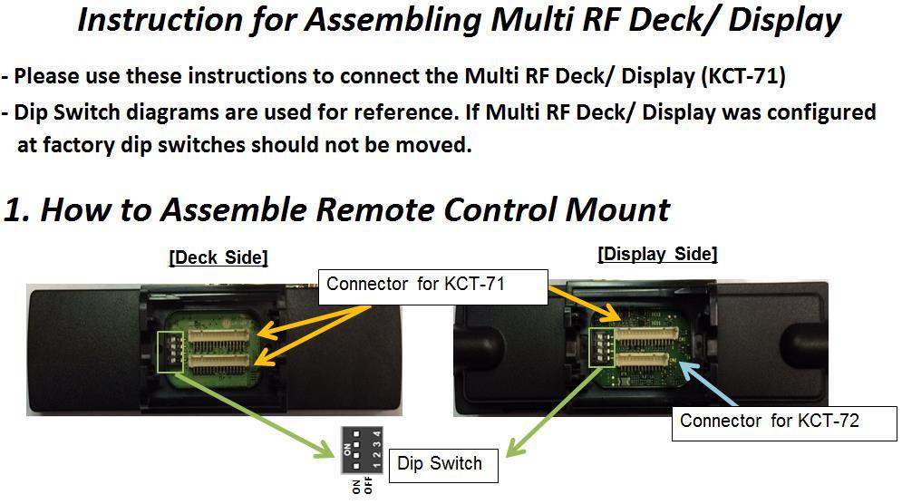
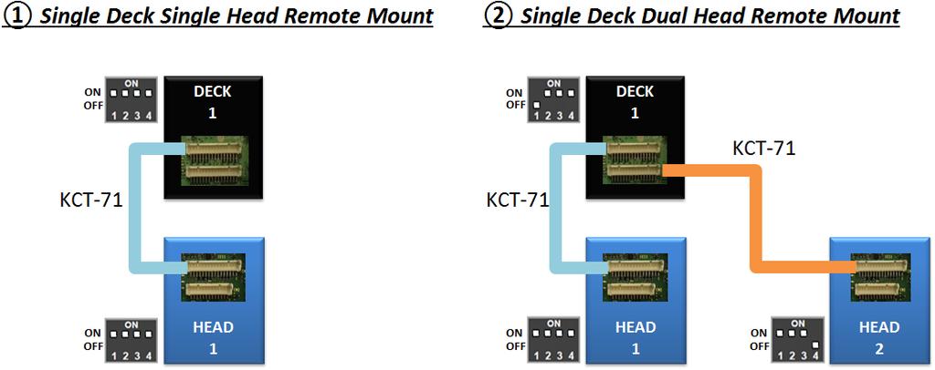
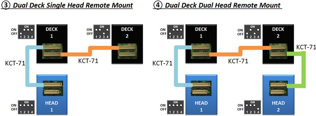
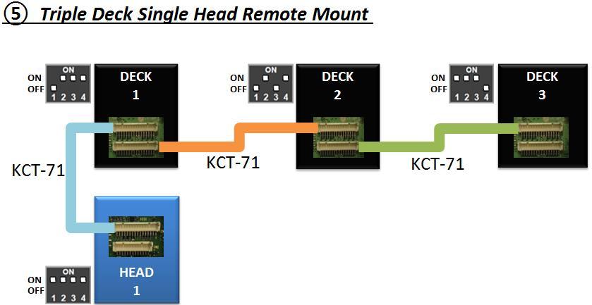
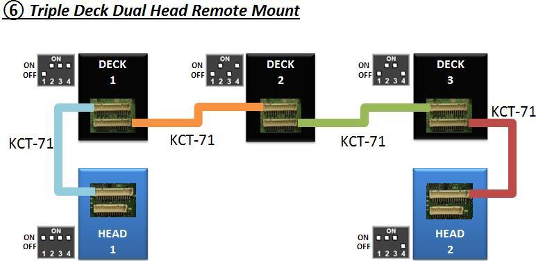
![reflects how they are displayed on the control head.] 2.](/docs-images/89/99263515/images/15-1.jpg "Connect all necessary KCT-71 cables between RF Decks and Heads as shown in the provided diagrams on next page. 3.")
15 4. Assemble Remote Configuration 1. Set DIP switches of each RF Deck and Control Heads as shown in the provided diagrams on next page. [Deck No. reflects how they are displayed on the control head.] 2. Connect all necessary KCT-71 cables between RF Decks and Heads as shown in the provided diagrams on next page. 3. Install accessories such as KAP-2, KCT-72 if they are needed. (The Service Manual for each model describes the installation and pin position.) Page 15
16 Page 16
17 Page 17
18 Page 18
19 Page 19
20 Page 20


, you can connect KRA-40GM to")
21 2. Pin position of KCT-72 KCH-20R KCT-72 KES-5 Pin No. Color Name 1 RED IGN 2 BLACK SB 3 LIGHT GREEN GND 4 LIGHT BLUE AUX_MIC 5 YELLOW AUX_ME 6 GRAY Ai1 7 WHITE Ai2 8 PURPLE Ao1 9 PINK Ao2 10 ORANGE SP- 11 BROWN SP+ 12 DARK GREEN GND * KES-5 cannot connect to KCH-19 because KCH-19 does not have speaker output port. 3. GPS Antenna (KRA040GM) If you use GPS Antenna(KRA-40GM), you can connect KRA-40GM to only Deck 1. The GPS data is transferred to Deck 2 and Deck 3 from Deck 1. Page 21
22 5. After Initial Setup After the initial set-up, as described in the previous sections, has been completed, firmware update and FPU programming may be performed via Control Head #1 without disassembling the configuration noted below. # of RF Deck Single RF Deck Dual RF Deck Triple RF Deck # of Control Head Single Head Dual Head Single Head Dual Head Single Head Dual Head Six Remote Mount Configuration Designs Head 1 Head 1 Head 1 Head 1 Head 1 Head 1 FPU Programming FPU Data Read/Write is performed in the Multi RF Deck Setup menu under Program. If you have another FPU data file that needs to replace the current selected file, specify the replacement data by Select File. If you need to modify a current selected file, Save as the data, first. Then, open the saved file to make changes. Select the saved file by Select File. Once each deck has a correct data file selected, then Write the data through Control Head 1 once. Page 22
RF Solution for LED Display Screen
 RF Solution for LED Display Screen Introduction RF is a kind of wireless telecommunication technology, now standard IEEE802.11B is much popular. Communication speed between server and terminal can reach
CONNECTOR A (BLACK 4 PIN) LED S CONNECTOR B (WHITE 4 PIN) CONNECTOR C (WHITE 5 PIN) CONNECTOR D (WHITE 2 PIN) 1x device. 2x - 10x
 LED S CONNECTOR B (WHITE 4 PIN) CONNECTOR C (WHITE 5 PIN) CONNECTOR D (WHITE 2 PIN) 1x device. 2x - 10x") SIC3-RFK FIRMWARE 2.0.4 A B CONNECTOR A (BLACK 4 PIN) TO BYPASS OR REMOTE STARTER LED S CONNECTOR B (WHITE 4 PIN) TO SOLACE ANTENNA ( NOT INCLUDED ) CONNECTOR C (WHITE 5 PIN) GRAY / BLACK - START / STOP
SIC3-RFK FIRMWARE 2.0.4 A B CONNECTOR A (BLACK 4 PIN) TO BYPASS OR REMOTE STARTER LED S CONNECTOR B (WHITE 4 PIN) TO SOLACE ANTENNA ( NOT INCLUDED ) CONNECTOR C (WHITE 5 PIN) GRAY / BLACK - START / STOP
SATELLITE TV OPERATION / TECHNICAL MANUAL. Eagle II Controller
 SATELLITE TV OPERATION / TECHNICAL MANUAL Eagle II Controller 10 May 2018 2 Index Warnings... 4 Mount Definitions... 5 Controller Views... 6 Configuration and Software Versions... 8 Menus and Operations...
Gazer VI700A-SYNC2 and VI700W- SYNC2 INSTALLATION MANUAL
 Gazer VI700A-SYNC2 and VI700W- SYNC2 INSTALLATION MANUAL Contents List of compatible cars... 3 Package contents... 4 Special information... 6 Car interior disassembly and connection guide for Ford Focus...
DX-10 tm Digital Interface User s Guide
 DX-10 tm Digital Interface User s Guide GPIO Communications Revision B Copyright Component Engineering, All Rights Reserved Table of Contents Foreword... 2 Introduction... 3 What s in the Box... 3 What
Extra long-range RFID (proximity) card reader
 card reader") GP90A Extra long-range RFID (proximity) card reader (1) Features: Extra long reading range of up to 90 cm with ISO-size passive RFID cards*, over 100 cm with special optimized passive cards High-precision
GP90A Extra long-range RFID (proximity) card reader (1) Features: Extra long reading range of up to 90 cm with ISO-size passive RFID cards*, over 100 cm with special optimized passive cards High-precision
Audio Design Associates (ADA)
") Manufacturer: Audio Design Associates (ADA) Integration Note Model Number(s): Tune Suite (Quadritune) Core Module Version: Comments: Quadritune v2.2, TFM-1 v2.1, HDM-1 v3.2, XM v2.01, Sirius v1.0 Document
Manufacturer: Audio Design Associates (ADA) Integration Note Model Number(s): Tune Suite (Quadritune) Core Module Version: Comments: Quadritune v2.2, TFM-1 v2.1, HDM-1 v3.2, XM v2.01, Sirius v1.0 Document
Intellian MIM Serial Number
 Intellian MIM Serial Number This serial number will be required for all troubleshooting or service calls made regarding this product. Notice All Right Reserved Intellian MIM and Intellian are the registered
Gazer VI700A-SYNC/IN and VI700W- SYNC/IN INSTALLATION MANUAL
 Gazer VI700A-SYNC/IN and VI700W- SYNC/IN INSTALLATION MANUAL Contents List of compatible cars... 3 Package contents... 4 Special information... 6 Car interior disassembly and connection guide for Ford
HC20 Healthcare Kit Installation Instructions
 Our HC20 installation kit uses technology that allows a standard hospital pillow speaker to control a TV and receive audio from the TV at the pillow speaker next to the patient. The HC20 product, when
SATELLITE TV OPERATION / TECHNICAL MANUAL. Eagle II Controller
 SATELLITE TV OPERATION / TECHNICAL MANUAL Eagle II Controller 8 Nov 2017 2 Index Warnings... 4 Mount Definitions... 5 Controller Views... 6 Configuration and Software Versions... 8 Menus and Operations...
Stevens SatComm FAQs For use with SatCommSet or Terminal Setup programs
 Stevens SatComm FAQs For use with SatCommSet or Terminal Setup programs Q. What are the channel assignments for On Air Test Mode? A. The assigned GOES test channels are as follows: GOES West 300 Baud:
Field Service Procedure Replacement GACP Control Panel Kit, ST24
 1. Brief Summary: Troubleshooting document for diagnosing a fault with and replacing the Graphic Antenna Control Panel (GACP) for the ST24 antenna. 2. Checklist: Verify Power to the GACP Verify Communications
Mortara X-Scribe Tango+ Interface Notes
 Mortara X-Scribe Tango+ Interface Notes To setup Tango+ with the X-Scribe stress system, simply follow the directions below. 1. Verify Correct RS-232 and ECG Trigger Cables RS-232 Cable used to communicate
Hardware User s Manual
 Hardware User s Manual Megapixel Day & Night Economy Bullet Network Camera English 1 Table of Contents Before You Use This Product... 2 Regulatory Information... 3 Chapter 1 - Package Contents... 4 Chapter
COPYRIGHT NOVEMBER-1998
 Application Notes: Interfacing AG-132 GPS with G-858 Magnetometer 25430-AM Rev.A Operation Manual COPYRIGHT NOVEMBER-1998 GEOMETRICS, INC. 2190 Fortune Drive, San Jose, Ca 95131 USA Phone: (408) 954-0522
HITS QT/QT+ Setup Instructions for QSD/QHD Services using: Drake SCT2x4 Headend Transcoder 2 Satellites/4 Multiplexes
 HITS QT/QT+ Setup Instructions for QSD/QHD Services using: Drake SCT2x4 Headend Transcoder 2 Satellites/4 Multiplexes Drake Transcoder Front /Rear View Setup and Programming Instructions: Input Setup Below
R4 AIS Class B Transponder
 Saab TransponderTech R4 AIS Class B Transponder Configuration Manual GENERAL Page 1 i Copyright The entire contents of this manual and its appendices, including any future updates and modifications, shall
Using SignalTap II in the Quartus II Software
 White Paper Using SignalTap II in the Quartus II Software Introduction The SignalTap II embedded logic analyzer, available exclusively in the Altera Quartus II software version 2.1, helps reduce verification
BMW12N-DYNAMIC KIT NTV-KIT717
 3950 NW 120 th Ave, Coral Springs, FL 33065 TEL 561-955-9770 FAX 561-955-9760 www.nav-tv.com info@nav-tv.com BMW12N-DYNAMIC KIT NTV-KIT717 Screen Connector Overview The BMW12-N kit interfaces 2 video inputs
DataSAT ACU-2 Controller Wiring Configuration - Operation
 DataSAT ACU-2 Controller Wiring Configuration - Operation This manual covers basic wiring, antenna controller configurations, and typical operation. For proper operation, wiring and configuration are very
InfiniTV 4 Installation Instructions
 InfiniTV 4 Installation Instructions 1. Obtain a CableCARD from your cable TV service provider 1. Call your cable TV service provider and tell them you need a multi-stream CableCARD (M-Card) for a Ceton
Configuration Vestas VMP3500
 Configuration Vestas VMP3500 1. Table of contents 1. Table of contents... 2 2. Introduction... 3 3. Vestas turbines (RCS)... 4 3.1. VMP 3500 controller... 4 3.2. Communication with the CT3230 current loop
Ten-Tec (865) Service Department:(865)
 Service Department:(865)") Ten-Tec (865) 453-7172 Service Department:(865) 428-0364 Installation Instructions for Ten-Tec Jupiter AT538K Tuner Kit The installation of the AT538K is divided into two steps. The first step is to reprogram
Ten-Tec (865) 453-7172 Service Department:(865) 428-0364 Installation Instructions for Ten-Tec Jupiter AT538K Tuner Kit The installation of the AT538K is divided into two steps. The first step is to reprogram
Quick Start for TrueRTA (v3.5) on Windows XP (and earlier)
 on Windows XP (and earlier)") Skip directly to the section that covers your version of Windows (XP and earlier, Vista or Windows 7) Quick Start for TrueRTA (v3.5) on Windows XP (and earlier) Here are step-by-step instructions to get
Skip directly to the section that covers your version of Windows (XP and earlier, Vista or Windows 7) Quick Start for TrueRTA (v3.5) on Windows XP (and earlier) Here are step-by-step instructions to get
Table of Contents. Versa TILE & Versa DRIVE D2 Quick Start Manual
 Versa TILE & Versa DRIVE D2 Table of Contents 1. Introduction 2 2. Versa TILE Assembly & Cabling 2 3. Computer & Versa DRIVE Connections 2 4. RasterMAPPER 3 5. Buffer Board 4 6. Testing the System 5 7.
USER MANUAL FOR CABLE RECEIVER KAON KCF-200CO KAON KCF-H220SCO
 USER MANUAL FOR CABLE RECEIVER KAON KCF-200CO KAON KCF-H220SCO SECURITY INSTRUCTIONS FOR USING THE RECEIVER Always fallow these instructions to avoid risk of injury or damaging the equipment. Before cleaning
Instruction for Locking Tuner s Carriage(s) before Shipping
 before Shipping") Instruction for Locking Tuner s Carriage(s) before Shipping Step 1. Configure tuner properties and verify connection From ATS block diagram view, double click on the tuner that needs to be locked. The
Instruction for Locking Tuner s Carriage(s) before Shipping Step 1. Configure tuner properties and verify connection From ATS block diagram view, double click on the tuner that needs to be locked. The
Scan Converter Quick Installation Guide
 Scan Converter Quick Installation Guide Software Note: No software is required to use your scan converter. Please complete the hardware installation and system setup before you determine the need to the
ImproX (TRT) Twin Remote Terminal INSTALLATION MANUAL
 Twin Remote Terminal INSTALLATION MANUAL") SPECIFICATIONS MODEL NUMBER: XRT910-0-0-GB-XX XRT911-0-0-GB-XX XTT911-0-0-NN-XX IMPROX TRT ImproX (TRT) Twin Remote Terminal INSTALLATION MANUAL Working Environment XRT910-0-0-GB-XX... (Aluminium Extruded
SPECIFICATIONS MODEL NUMBER: XRT910-0-0-GB-XX XRT911-0-0-GB-XX XTT911-0-0-NN-XX IMPROX TRT ImproX (TRT) Twin Remote Terminal INSTALLATION MANUAL Working Environment XRT910-0-0-GB-XX... (Aluminium Extruded
BMW12N-H NTV-KIT791. Kit Contents. BMW12N-H Interface. Interface Power Harness
 3950 NW 120 th Ave, Coral Springs, FL 33065 TEL 561-955-9770 FAX 561-955-9760 www.nav-tv.com info@nav-tv.com BMW12N-H NTV-KIT791 Screen Connector Overview The BMW12N-H kit interfaces 2 composite video
Wireless Studio. User s Guide Version 5.1x Before using this software, please read this manual thoroughly and retain it for future reference.
 4-743-161-12 (1) Wireless Studio User s Guide Version 5.1x Before using this software, please read this manual thoroughly and retain it for future reference. DWR-R01D/R02D/R02DN/R03D 2018 Sony Corporation
INSTALLATION MANUAL. Full Plug n Play kit for installing Sirius Radio in compatible vehicles
 ARC-MFSAT357 ARC-MFSAT357 INSTALLATION MANUAL Full Plug n Play kit for installing Sirius Radio in compatible vehicles Required for Install: 1. Satellite Ready MyFord Vehicle 2. ARC-MFSAT357 Installation
Prism TM450 Installation Guide For JBus 1708 and 1939
 Prism TM450 Installation Guide For JBus 1708 and 1939 Document Number: 1624-0301 00 Date: May 5, 2010 Table of Contents Overview... 1 Kit Components... 1 Differences between the TM450 and the TM2J....
More Skills 14 Watch TV in Windows Media Center
 M05_TOWN5764_01_SE_SM5.QXD 11/24/10 1:08 PM Page 1 Chapter 5 Windows 7 More Skills 14 Watch TV in Windows Media Center You can watch and record broadcast TV in Windows Media Center. To watch and record
Welch Allyn CardioPerfect Workstation Tango+ Interface Notes
 Welch Allyn CardioPerfect Workstation Tango+ Interface Notes To setup Tango+ with the CardioPerfect stress system, simply follow the directions below. 1. Verify Correct RS-232 and ECG Trigger Cables RS-232
Agilent 11713A Attenuator/Switch Driver
 Agilent A Attenuator/Switch Driver Configuration Guide This configuration guide will help you through the process of configuring a switching system utilizing Agilent s A attenuator/switch driver. The A
Before you can install your LCD TV on the wall, you must fi rst remove the base using the steps below:
 Quick Start Guide English CONTENTS INSTALLING LCD TV ON THE WALL.. TV CHANNEL INSTALLATION........ PRESENTATION OF THE LCD TV...... ACCESSORIES.................... BATTERY INSTALLATION............ REMOTE
US Rev. E, Copyright 1 September 2008 CAUTION:
 The Spectracom NetClock Wireless Clocks are cost-effective facilities clocks that display synchronized time across a campus, within a structure, or in a variety of other installations. A Wireless Clock
Using LightSpace CMS for User Created Calibration LUTs
 20140130 Flanders Scientific, Inc. 6215 Shiloh Crossing Suite G Alpharetta, GA 30005 Phone: +1.678.835.4934 Fax: +1.678.804.1882 E-Mail: Support@FlandersScientific.com www.flandersscientific.com 1. If
Connecting the KPA500 to a Kenwood TS590s Transceiver
 Connecting the KPA500 to a Kenwood TS590s Transceiver The TS-590 does have a KEY OUT signal that will need to be connected to the KPA500's PA KEY jack. This 'arms' the KPA500 for transmit whenever the
Evaluation Board For ADF Integrated VCO & Frequency Synthesizer
 a Evaluation Board For ADF4360-1 Integrated VCO & Frequency Synthesizer EVAL-ADF4360-1EB1 FEATURES Self-Contained Board for generating RF frequencies Flexibility for Reference Input, Output frequency,
IP LIVE PRODUCTION UNIT NXL-IP55
 IP LIVE PRODUCTION UNIT NXL-IP55 OPERATION MANUAL 1st Edition (Revised 2) [English] Table of Contents Overview...3 Features... 3 Transmittable Signals... 3 Supported Networks... 3 System Configuration
with the Field-IQ Crop Input Control System
 with the Field-IQ Crop Input Control System Quick Reference Card CONNECTING THE SYSTEM Ag25 GNSS antenna (P/N 68040-OOS) TNC/TNC right-angle cable (P/N 50449) Cable assembly, display to Field-IQ (P/N 50449)
Solutions for a Real Time World. Unigen Corp. Wireless Module Products. PAN Radio Modules Demonstration & Evaluation Kit UGWxxxxxxxxx (Part Number)
") Unigen Corp. Wireless Module Products PAN Radio Modules Demonstration & Evaluation Kit UGWxxxxxxxxx (Part Number) Issue Date: November 19, 2008 Revision: 1.0-1 REVISION HISTORY Rev. No. History Issue Date
Unigen Corp. Wireless Module Products PAN Radio Modules Demonstration & Evaluation Kit UGWxxxxxxxxx (Part Number) Issue Date: November 19, 2008 Revision: 1.0-1 REVISION HISTORY Rev. No. History Issue Date
Modification Information (MOD) For. Last Updated: Sep, Type:
 For. Last Updated: Sep, Type:") Modification Information (MOD) For TKR-750/850 Version2 TKR-751/851 Version: 1.02 USA Last Updated: Sep, 2005 Language: English Type: K About Copyright All copyrights and other intellectual property rights
Modification Information (MOD) For TKR-750/850 Version2 TKR-751/851 Version: 1.02 USA Last Updated: Sep, 2005 Language: English Type: K About Copyright All copyrights and other intellectual property rights
N+1 Redundancy with the VCom HD4040 Upconverter
 N+1 Redundancy with the VCom HD4040 Upconverter Document ID: 47164 Contents Introduction Prerequisites Requirements Components Used Conventions Set Up Communication with the Upconverter VCom Dual4040D
Holtek Semiconductor Inc. Project Name Update Date Author Version Page Holtek e-writerpro Q&A Sky /7
 Holtek e-writerpro Q&A 2015-04-03 Sky 1.01 1/7 Holtek e-writerpro Q&A Revision History Version Date Description Author 1.00 2013-11-07 Create Sky 1.01 2015-04-03 Add 9 and 10 items Sky Check the following
Quad Video Switching Box User Manual
 Quad Video Switching Box User Manual The Solution for Vehicle safety Table of Contents PRECAUTIONS 3 IDENTIFYING THE PARTS 4 INSTALLATION DIAGRAM...5 Camera or video input/output.. 5 Camera or video display...6
GWL/ Power Group Technology Solutions Stay Powered for the Future
 GWL/ Power Group Technology Solutions Stay Powered for the Future BMS2405 CONNECTION GUIDE: This is simple step-by-step manual how to CONNECT AND proceed basic SETUP of BMS2405. In following example connection
Yaesu FT-950 and FT-450D with KPA/KAT500 Power Combo
 Yaesu FT-950 and FT-450D with KPA/KAT500 Power Combo The Yaesu FTdx1200, FT-450D and FT-950 series radio can be connected to the KAT/KPA500 combo using the Key signal available on the rear panel of the
RADIO FREQUENCY SYSTEMS
 RADIO FREQUENCY SYSTEMS Optimizer RT FAQ s Q. What information is require before running the software? The Serial Number of each ACU MUST be recorded with the Model number of the antenna that it is attached
Aeroforce FAQ. 2. Before I purchase, how do I know what parameters will be supported on my particular vehicle?
 Aeroforce FAQ 1. My gauge just cycles on and off, what s wrong? 2. Before I purchase, how do I know what parameters will be supported on my particular vehicle? 3. I would like to purchase a second gauge
2.0 Installation Guide
 2.0 Installation Guide Mediatune 2.0 was designed to work with the CHROME browser on the PC and the Safari browser on the ipad. While you may be able to get other browsers to work, you will have the best
Noise Detector ND-1 Operating Manual
 Noise Detector ND-1 Operating Manual SPECTRADYNAMICS, INC 1849 Cherry St. Unit 2 Louisville, CO 80027 Phone: (303) 665-1852 Fax: (303) 604-6088 Table of Contents ND-1 Description...... 3 Safety and Preparation
Personal Information Page
 Rev. 08.29.07 Personal Information Page Installing Dealer Name Date of Installation Day Month Year Type of System Executive MD500 MD1000.2 MHDTV MD5Slim MSD60 Freedom (not recommended) Serial Number of
Booya16 SDR Datasheet
 Booya16 SDR Radio Receiver Description The Booya16 SDR radio receiver samples RF signals at 16MHz with 14 bits and streams the sampled signal into PC memory continuously in real time. The Booya software
EAGLE RE-1 CONTROLLER For Use On MotoSAT HD Mounts
 EAGLE RE-1 CONTROLLER For Use On MotoSAT HD Mounts Supported Systems HD SL5 DirecTV HD DP3 Dish Network HD SC2 SHAW HD DP3 BELL TV EXECUTIVE DirecTV 101 Dish Network 119 MSC-60 SHAW MD-500 Dish Network
VL6-CADVD. Specification & Installation. Compatible with Comand APS DVD (manufactured by Siemens/VDO) also referred to by Mercedes Benz as NTG1
 also referred to by Mercedes Benz as NTG1") Updated date: 2017.05.31 Model: RGB-LE-V3.1 / Product code: RB-100126-013 VL6-CADVD Specification & Installation Compatible with Comand APS DVD (manufactured by Siemens/VDO) also referred to by Mercedes
Updated date: 2017.05.31 Model: RGB-LE-V3.1 / Product code: RB-100126-013 VL6-CADVD Specification & Installation Compatible with Comand APS DVD (manufactured by Siemens/VDO) also referred to by Mercedes
The amazing power of FiOS starts here.
 SELF-INSTALLATION GUIDE The amazing power of FiOS starts here. LET S GET STARTED Welcome to a network that s light years ahead. Welcome to life on FiOS. Congratulations on choosing Verizon FiOS! You re
Viavi T-BERD 5800 CPRI Testing Guide with ALU BBU Emulation
 Viavi T-BERD 5800 CPRI Testing Guide with ALU BBU Emulation Scope Version 4 January 2018 Firmware 26.0.0.6c1973b or Later REQUIRED! This document describes Common Public Radio Interface (CPRI) testing
Scan Converter Installation Guide
 Scan Converter Installation Guide Software on supplied disks Please note: The software included with your scan converter is OPTIONAL. It is not needed to make the scan converter work properly. This software
HV-122-DCA DVB-T 2-Way Diversity Receiver Box Quick Installation Guide
 HV-122-DCA DVB-T 2-Way Diversity Receiver Box Quick Installation Guide PACKAGE CONTENTS 4 FRONT PANEL VIEW 4 BACK PANEL VIEW 4 BOARD VIEW 5 IR REMOTE CONTROLLER-TYPE A 6 FILL BATTERY TO IR CONTROLLERS:
Connecting the Elecraft Power Combo to the Kenwood TS-2000 series Transceiver
 Connecting the Elecraft Power Combo to the Kenwood TS-2000 series Transceiver This Application Note describes how any model of the TS-2000 series transceiver can be connected the Elecraft Power Combo,
NNG-GM2 Navigation interface for GM vehicles equipped with LVDS MYLink/CUE NTV-KIT552
 3950 NW 120 th Ave, Coral Springs, FL 33065 TEL 561-955-9770 FAX 561-955-9760 NNG-GM2 Navigation interface for GM vehicles equipped with LVDS MYLink/CUE NTV-KIT552 This installation manual is for NNG-GM2
Hardware Setup. HP Dual TV Tuner/Digital Video Recorder. Document Part Number:
 Hardware Setup HP Dual TV Tuner/Digital Video Recorder Document Part Number: 374787-001 November 2004 This guide provides steps to help you set up your HP Dual TV Tuner/Digital Video Recorder hardware
EAGLE RE-1 CONTROLLER
 EAGLE RE-1 CONTROLLER For Use On ALL MotoSAT Mounts Supported Systems HD SL5 DirecTV HD DP3 Dish Network HD SC2 SHAW HD DP3 BELL TV EXECUTIVE 18" DirecTV 101 Dish Network 119 MSC-60 SHAW MD-500 Dish Network
SXGA096 DESIGN REFERENCE BOARD
 SXGA096 DESIGN REFERENCE BOARD For Use with all emagin SXGA096 OLED Microdisplays USER S MANUAL VERSION 1.0 TABLE OF CONTENTS D01-501152-01 SXGA096 Design Reference Board User s Manual i 1. INTRODUCTION...
TVS-2-TAIT VPU-15-TAIT
 TVS-2-TAIT High Level Rolling Code Scrambler for the Tait Orca & TM-8000 Radios VPU-15-TAIT Voice Inversion Scrambler for the Tait Orca & TM-8000 Radios Manual Revision: 2018-03-05 Rev B Covers Software
Be sure to run the vehicle engine while using this unit to avoid battery exhaustion.
 CAUTION: TO REDUCE THE RISK OF ELECTRIC SHOCK DO NOT REMOVE COVER (OR BACK) NO USER-SERVICEABLE PARTS INSIDE REFER SERVICING TO QUALIFIED SERVICE PERSONNE; Please Read all of these instructions regarding
MENU EXECUTE Shiloh Road Alpharetta, Georgia (770) FAX (770) Toll Free
 FAX (770) Toll Free") Instruction Manual Model 2584-31 Combiner May 2011, Rev. A RF MONITOR GAIN = -15 MENU MODEL 2584 COMBINER CROSS TECHNOLOGIES INC. ALARM REMOTE POWER EXECUTE Data, drawings, and other material contained
Instruction Manual Model 2584-31 Combiner May 2011, Rev. A RF MONITOR GAIN = -15 MENU MODEL 2584 COMBINER CROSS TECHNOLOGIES INC. ALARM REMOTE POWER EXECUTE Data, drawings, and other material contained
NewScope-7A Operating Manual
 2016 SIMMCONN Labs, LLC All rights reserved NewScope-7A Operating Manual Preliminary May 13, 2017 NewScope-7A Operating Manual 1 Introduction... 3 1.1 Kit compatibility... 3 2 Initial Inspection... 3 3
1 Unpack the projector. Quick Setup. Epson PowerLite 62c/82c. User s Guide. You should have the following items: Computer cable. Power cord.
 Epson PowerLite 62c/82c Quick Setup 1 Unpack the projector You should have the following items: Projector Power cord Computer cable Projector remote control Password protect sticker User s Guide CD-ROM
USER MANUAL. 840Hxl Pattern Generator MODEL: P/N: Rev 5
 KRAMER ELECTRONICS LTD. USER MANUAL MODEL: 840Hxl Pattern Generator P/N: 2900-300032 Rev 5 Contents 1 Introduction 1 2 Getting Started 2 2.1 Achieving the Best Performance 2 2.2 Safety Instructions 2
Any feature not specifically noted as supported is not supported.
 Manufacturer: ELAN Integration Note Model Number(s): EL-4KM-VW44 (Device Ver 2.20; Web Module Ver 6.23) Minimum Core Module Version: Document Revision Date: 8.1.395 5/11/2017 OVERVIEW AND SUPPORTED FEATURES
Instruction Manual Model 2412-x08 Multi-Channel AGC Amplifier
 Instruction Manual Model 2412-x08 Multi-Channel AGC Amplifier 2412-408 Four Channel 2412-308 Three Channel 2412-208 Two Channel 2412-108 One Channel March 2017, Rev. A 1 2 3 4 A B CHANNEL STATUS REMOTE
Data Acquisition Using LabVIEW
 Experiment-0 Data Acquisition Using LabVIEW Introduction The objectives of this experiment are to become acquainted with using computer-conrolled instrumentation for data acquisition. LabVIEW, a program
VGA AUDIO AUDIO MATRIX SWITCHER S MANUAL
 VGA AUDIO AUDIO MATRIX SWITCHER S MANUAL Milestone s VGA AUDIO AUDIO MATRIX Switcher is a unit whereby multiple (2/4/8) VGA AUDIO AUDIO input can be switched to two (2) or multiple (simultaneous) VGA AUDIO
DTA INSTALLATION PROCESS & USER GUIDE FOR SPECTRUM BUSINESS CUSTOMERS
 DTA INSTALLATION PROCESS & USER GUIDE FOR SPECTRUM BUSINESS CUSTOMERS This guide is intended for owners or managers and front desk personnel. This guide is not intended for guests. Customer Care 1-800-314-7195
Modbus for SKF IMx and Analyst
 User manual Modbus for SKF IMx and SKF @ptitude Analyst Part No. 32342700-EN Revision A WARNING! - Read this manual before using this product. Failure to follow the instructions and safety precautions
Model#: IN-DI2MIRF 2MP Indoor Dome with True Day/Night, IR, Basic WDR, Fixed lens
 Model#: IN-DI2MIRF 2MP Indoor Dome with True Day/Night, IR, Basic WDR, Fixed lens Hardware User Manual (PoE) Ver.2013/01/17 Table of Contents 0. Precautions 3 1. Introduction 4 Package Contents...4 Features
0.56" 4 Digital Blue LED Panel Meter (rescalable) User s Guide
 User s Guide") 0.56" 4 Digital Blue LED Panel Meter (rescalable) User s Guide 2004-2009 Sure Electronics Inc. ME-SP037B_Ver1.0 0.56" 4 DIGITAL BLUE LED PANEL METER (RESCALABLE) USER S GUIDE Table of Contents Chapter
0.56" 4 Digital Blue LED Panel Meter (rescalable) User s Guide 2004-2009 Sure Electronics Inc. ME-SP037B_Ver1.0 0.56" 4 DIGITAL BLUE LED PANEL METER (RESCALABLE) USER S GUIDE Table of Contents Chapter
Commissioning Guide. firepickdelta. Commissioning Guide. Written By: Neil Jansen firepickdelta.dozuki.com Page 1 of 22
 firepickdelta Commissioning Guide Written By: Neil Jansen 2017 firepickdelta.dozuki.com Page 1 of 22 Step 1 Pre-Requisites Before commissioning, please make sure ALL of the following steps have been completed,
Operation and Installation Guide
 Operation and Installation Guide HDS2800 Series Encoder Modulator High Definition (HD) Digital COFDM MPEG2 and H.264 Modulator with IP Multicast. 19 Rack Mount Revision 4.0 Firmware version Released File
SPECIFICATION FOR APPROVAL
 SPECIFICATION FOR APPROVAL (ANALOG RGB AND VIDEO INTERFACE CONTROLLER FOR VGA/SVGA/XGA RESOLUTION TFT-LCDs) MODEL NO : AP4300 SERIES BUYER S PARTNO: APPROVED REFERENCE (PLEASE RETURN ONE OF THESE TO US
DVB-LR10. Compatible with Land Rover touch-screen navigation systems version 2
 dvblogic DVB-T Tuner Compatible with Land Rover touch-screen navigation systems version 2 Product features full plug and play vehicle-specific dual DVB-T Tuner with two active DVB-T glass-mount antennas
1 Unpack. Taking the TV Out of the Box. Included in this Box. Stand Parts and Cables. Remote Control. Also included
 1 Unpack Taking the TV Out of the Box Warning: Do not touch the TV s screen when you take it out of the box. Hold it by its edges only. If you touch the screen, you can cause the TV panel to crack. Included
MONITOR POWER Shiloh Road Alpharetta, Georgia (770) FAX (770) Toll Free
 FAX (770) Toll Free") Instruction Manual Model 2099-10xx 10MHz Frequency Source April 2014, Rev. H MENU INTERNAL LEVEL = +10dBm MONITOR POWER 1 2 MODEL 2099 FREQUENCY SOURCE CROSS TECHNOLOGIES INC. ALARM OVEN REMOTE EXECUTE
Instruction Manual Model 2099-10xx 10MHz Frequency Source April 2014, Rev. H MENU INTERNAL LEVEL = +10dBm MONITOR POWER 1 2 MODEL 2099 FREQUENCY SOURCE CROSS TECHNOLOGIES INC. ALARM OVEN REMOTE EXECUTE
CompactMax-2 DVB-S/S2 TO DVB-T2 TRANSMODULATOR - 0 MI2100 -
 CompactMax-2 DVB-S/S2 TO DVB-T2 TRANSMODULATOR - 0 MI2100 - SAFETY NOTES Read the user s manual before using the equipment, mainly "SAFETY RULES" paragraph. The symbol on the equipment means "SEE USER
TeamWork Kits Installation Guide
 TX 0 RX COM +5V APARATUS US TeamWork Kits Installation Guide TeamWork 400 and TeamWork 600 Kits The TeamWork 400 and TeamWork 600 kits consist of an HDMI switcher, system controller, Cable Cubby, and cables
Safety warning Important Safety Instructions. Wall Mount Specifications. Electronic Program Guide. Lock Menu 18. PVR File System
 LT-32N370Z 32 INPUT Safety warning Important Safety Instructions Wall Mount Specifications Electronic Program Guide Lock Menu 18 PVR File System 11 11 11 14 15 16 17 19 20 21 21 22 23 24 25 INPUT AAA
Pulse Biomedical QRS-Card Tango M2 Interface Notes
 Pulse Biomedical QRS-Card Tango M2 Interface Notes To setup Tango M2 with your stress system, simply follow the directions below. 1. Verify Correct RS-232 and ECG Trigger Cables RS-232 Cable used to communicate
P-2 Installing the monitor (continued) Carry out as necessary
 Carry out as necessary") P-2 Installing the monitor (continued) Carry out as necessary Using the monitor without the bezel MDT552S satisfies the UL requirements as long as it is used with the bezel attached. When using the monitor
P-2 Installing the monitor (continued) Carry out as necessary Using the monitor without the bezel MDT552S satisfies the UL requirements as long as it is used with the bezel attached. When using the monitor
Owner's Manual DIGITAL TO ANALOG BROADCAST CONVERTER WITH REMOTE CONTROL. Model: CVD508 PLEASE READ BEFORE OPERATING THIS EQUIPMENT.
 Size: 148.5(W) x 210(H)mm (A5) DIGITAL TO ANALOG BROADCAST CONVERTER WITH REMOTE CONTROL Owner's Manual PLEASE READ BEFORE OPERATING THIS EQUIPMENT. Model: CVD508 FCC NOTICE: To assure continued compliance,
RDS: The RDS, or Radio Data System, is supported in the g! interface where available.
 Manufacturer: Integra Integration Note Model Number(s): Integra 20.3/30.3/40.3/50.3/70.3/80.3 Core Module Version: 5.4 Comments: FW 1.09 (1091-0999-0210-9105) Document Revision Date: 1/15/2013 OVERVIEW
USER MANUAL. 840Hxl Pattern Generator MODEL: P/N: Rev 7
 KRAMER ELECTRONICS LTD. USER MANUAL MODEL: 840Hxl Pattern Generator P/N: 2900-300032 Rev 7 Contents 1 Introduction 1 2 Getting Started 2 2.1 Achieving the Best Performance 2 2.2 Safety Instructions 2
Revision Protocol Date Author Company Description 1.1 May 14, Seth LOUTH Revised for formatting
 PRODUCT ADC TOPIC ODETICS TCS-2000 CART MACHINE DATE: May 14, 1999 REVISION HISTORY Revision Protocol Date Author Company Description 1.1 May 14, Seth LOUTH Revised for formatting 1999 Olitzky 1.0 Aug.
Yellow Frog. Manual Version 1.1
 Yellow Frog Manual Version 1.1 1 YellowFrog Contents PC Requirements...... 2 YellowFrog Power Meter Measurement.... 3 YellowFrog PC Software..... 3 Main Screen....... 4 Input Overload....... 5 Battery
VNS2210 Amplifier & Controller Installation Guide
 VNS2210 Amplifier & Controller Installation Guide VNS2210 Amplifier & Controller Installation 1. Determine the installation location for the VNS2210 device. Consider the following when determining the
Troubleshooting. 1. Symptom: Status indicator (Red LED) on SSR is constant on. 2. Symptom: Output indicator (Yellow LED) on SSR is flashing.
 on SSR is constant on. 2. Symptom: Output indicator (Yellow LED) on SSR is flashing.") Product Data Electrical Data SST (Transmitter) SSR (Receiver) Supply voltage 18 30 V dc Max. Voltage ripple 15 % (within supply range) Current consumption 100 ma (RMS) 75 ma Digital - 100 ma Max. outputs
Product Data Electrical Data SST (Transmitter) SSR (Receiver) Supply voltage 18 30 V dc Max. Voltage ripple 15 % (within supply range) Current consumption 100 ma (RMS) 75 ma Digital - 100 ma Max. outputs