The tracer - A dual range tester for semiconductors and other components.
|
|
|
- Loreen Horton
- 5 years ago
- Views:
Transcription
1 The tracer - A dual range tester for semiconductors and other components. Introduction The Electro resales tracer is a modern implementation of a testing device developed originally to assist service professionals who had access to an oscilloscope with identification of component types and possible non-working conditions of these same components. The circuit origin is thought to have been from the US Military, but this is not certain. Original implementations involved cross connecting the scope inputs to a low voltage AC source, via current limit resistors, this led to its name as The Octopus tester, due to the tangle of wires this created. This implementation tidies all these wires into a PC layout and minimizes the clutter. Two levels of current limit are available via an on board switch the use of which is described herein. Packing List (DRT + Cables & Power Pack Set) Your purchase should include the following items: 1. The Dual Range tester box (Known in this guide as the DRT ) 2. One set of red/black test leads Banana to clips 3. A pair of BNC BNC cables V AC : 12 Volt AC Power Pack 5. Link to these instructions If the basic unit has been purchased only the Dual range tester box is included, no cables/power Pack Check the contents after opening the package and report any missing items or other issues immediately. A note about Oscilloscopes 1. The DRT is best used with an analog scope (one with a CRT), it will also work with a digital scope, the DRT has not been tested with any of the USB scopes or other scope types such as those based on Arduino/PIC technology or those that require a computer to function. 2. The oscilloscope to be used in conjunction with the tester needs to be a 2 channel unit with settings that allow it to be configured to work in XY mode. 3. Most 2 channel scopes can be used, the higher the frequency response of the scope, the more versatile the testing, but a 5MHz unit is as good as a 100MHz unit.
2 Initial Setup The following steps allow the easy first use of the DRT. 1. Connect the two BNC BNC cables to the DRT and then connect the one marked X to CH 1 or X on your oscilloscope, and the one marked Y to CH 2 or Y on the scope. 2. Connect the power pack barrel jack to the matching socket on the DRT. Ensure the DRT on/off switch is in the off position and then plug in the power pack to a suitable 110 Volt wall socket. a. Note the power pack supplied is only suitable for 110 Volt AC supplies. 3. Connect the test lead set to the corresponding banana jacks on the DRT. While polarity does not matter, connecting red to red and black to black just seems right. 4. Connect your oscilloscope in XY mode. Please refer to your user manual for the correct settings for your scope. a. We are unable to provide advice on the settings your specific oscilloscope requires. 5. With the range switch set to either the High or Low position; switch on the DRT by moving the on/off switch to the on position. A horizontal straight line trace should appear on the scope. Adjust the scope controls to achieve the correct intensity and position of the line, which is best centered on screen. Adjust the Volts/Div. control to make the line about 4 grid units wide a. If the line appears as vertical, swap the X Y BNC cables. 6. With the unit setup and power applied test initial operation by shorting the red and black test leads together, the horizontal line on the scope should become a vertical line, and revert back to a horizontal line when the leads are no longer shorted. This concludes the initial set up. Basic Operation After setup the DRT can be put to work. Components to be tested are connected to the test leads and the display on the scope will change to reveal various patterns that indicate operation, these patterns will become well known after using the DRT for a little while. Some patterns are standard across devices and some vary even within the same device. For instance silicon diodes and small signal diodes tend to all have a similar pattern shape, with some variation occurring from device to device in the length of the waveform shape arms. When connecting the DRT to a transformer though the patterns achieved can vary depending on the winding tested, or the portion of the winding. This is when use of the low or high current switch becomes an important tool. Another example is illustrated below, where different pattern shapes is achieved with the same component depending on the setting of the High/Low switch.


3 In this example a low voltage (35VDC) 470uF electrolytic capacitor is connected to the test leads and the pattern achieved is markedly different depending on the switch setting. See the photos of actual screen shots; At times the oscilloscope controls may need altering to get the desired pattern shape and size, but often use of the High Low switch will negate this need to alter the scope settings.
4 A good practice to adopt is to start all measurements with the DRT set to the low current setting, observe the waveform pattern achieved and then briefly move the switch to the high setting to determine if a better representation is possible. On the next page a number of representative waveforms are shown to guide initial testing. Over time and with use of the DRT you will quickly build up a knowledge of what trace is created for what component, keeping a note/drawing of this will aid future determinations and troubleshooting.
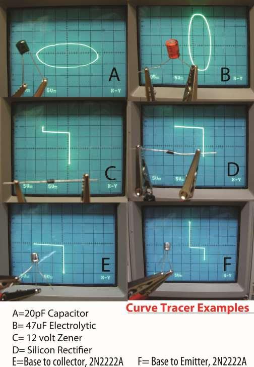
5
6 LIABILITY DISCLAIMER A person who constructs or works on electronic equipment may be exposed to hazards, including physical injury, the risk of electric shock or electrocution.. These hazards can result in health problems, injury, or death. Only qualified persons who understand and are willing to bear these risks themselves should attempt the construction of electronic equipment. By purchasing this item, the buyer acknowledges these risks. There is a risk of electric shock, electrocution, burns, or fires that is inherent in the construction and use of electronic equipment. By purchasing this item, the buyer acknowledges these risks. IN NO EVENT SHALL THE SELLER BE LIABLE FOR ANY SPECIAL, INCIDENTAL OR CONSEQUENTIAL DAMAGES OF ANY NATURE including, but not limited to, property damage, personal injury, death or legal expenses. Buyer's recovery from Seller for any claim shall not exceed the purchase price paid by Buyer for the goods, irrespective of the nature of the claim, whether in warrant, contract or otherwise. By purchasing this item, BUYER AGREES TO INDEMNIFY, DEFEND AND HOLD SELLER HARMLESS FROM ANY CLAIMS BROUGHT BY ANY PARTY REGARDING ITEMS SUPPLIED BY SELLER AND INCORPORATED INTO THE BUYER'S PRODUCT.
Getting started with the Time Domain Reflectometer
 Getting started with the Time Domain Reflectometer Background The Time Domain Reflectometer (Hereafter called a TDR) is designed to be used with an oscilloscope to allow simple measurements to be conducted
Parts Checklist - Please note there is no resistor R3. Diodes, LED and transistors are polarized see construction stages
 Xtal Check Kit build Read me first! -------- UPDATED GUIDE------ September 12, 2018--------- The following steps are designed to get your Xtal check kit built and operational. This is a good beginner s
1X4 HDMI Splitter with 3D Support
 AV Connectivity, Distribution And Beyond... VIDEO WALLS VIDEO PROCESSORS VIDEO MATRIX SWITCHES EXTENDERS SPLITTERS WIRELESS CABLES & ACCESSORIES 1X4 HDMI Splitter with 3D Support Model #: SPLIT-HDM3D-4
Metal Electrode Meter
 Metal Electrode Meter INSTRUCTION MANUAL FOR Metal Electrode Meter MODEL 2900 Serial # Date PO Box 850 Carlsborg, WA 98324 U.S.A. 360-683-8300 800-426-1306 FAX: 360-683-3525 http://www.a-msystems.com Version
Trusted 40 Channel Analogue Input FTA
 PD-T8830 Trusted Trusted 40 Channel Analogue Input FTA Product Overview The Trusted 40 Channel Analogue Input Field Termination Assembly (FTA) T8830 is designed to act as the main interface between a field
Industrial Monitor Update Kit
 Industrial Monitor Update Kit (Bulletin Number 6157) Installation Instructions 2 Table of Contents Table of Contents Industrial Monitor Update Kit... 3 Overview... 3 Part 1 - Initial Preparation... 5 Part
Quick Start. RSHS1000 Series Handheld Digital Oscilloscope
 Quick Start RSHS1000 Series Handheld Digital Oscilloscope General Safety Summary Carefully read the following safety precautions to avoid personal injury and prevent damage to the instrument or any products
MASTR II BASE STATION 12/24V POWER SUPPLY 19A149979P1-120 VOLT/60 Hz 19A149979P2-230 VOLT/50 Hz
 Mobile Communications MASTR II BASE STATION 12/24V POWER SUPPLY 19A149979P1-120 VOLT/60 Hz 19A149979P2-230 VOLT/50 Hz CAUTION THESE SERVICING INSTRUCTIONS ARE FOR USE BY QUALI- FIED PERSONNEL ONLY. TO
Is Now Part of To learn more about ON Semiconductor, please visit our website at
 Is Now Part of To learn more about ON Semiconductor, please visit our website at www.onsemi.com ON Semiconductor and the ON Semiconductor logo are trademarks of Semiconductor Components Industries, LLC
HDMI Extender over UTP Cable
 User Manual HDMI Extender over UTP Cable VHDE-300 Tx Rx Features.. Extends HDMI 1080p AV and IR Signals Transmission distance up to 60m/200ft via CAT6 cable or higher grade cable 5V DC, 1A Important Safety
GEKCO SUBCARRIER REFERENCE OSCILLATOR MODEL SRO10 OPERATION/SERVICE MANUAL
 GEKCO MODEL SRO10 SUBCARRIER REFERENCE OSCILLATOR OPERATION/SERVICE MANUAL GEKCO Labs PO Box 642 Issaquah, WA 98027 (425) 392-0638 P/N 595-431 REV 5/98 Copyright c 1998 GEKCO Labs All Rights Reserved Printed
SyncGen. User s Manual
 SyncGen User s Manual 1 IMPORTANT SAFETY INSTRUCTION READ FIRST This symbol, whenever it appears, alerts you to the presence of uninsulated dangerous voltage inside the enclosure-voltage that may be sufficient
Installation and Operation Manual
 PROBLEM SOLVED Installation and Operation Manual INC AES DA 2x6 Six-output, two-input AES/EBU Digital Audio Distribution Amplifier Manual update: 9/17/2015 If you need a firmware upgrade, contact Broadcast
QDA4-44 RF Amp/Combiner
 Product Manual QDA4-44 RF Amp/Combiner May 17, 2012 Table of Contents Table of Contents... 2 Overview... 3 Specifications... 4 Installation... 5 Basic Setup... 5 Rack Mounting... 6 RK2 Dual Rack Kit with
Trusted TMR I/O SmartSlot Slot Cables
 PD-TC500 Trusted Trusted TMR I/O SmartSlot Slot Cables Product Overview This document provides detailed information for the types of Trusted input/output (I/O) Cables available within the SmartSlot group.
University of Utah Electrical & Computer Engineering Department ECE1050/1060 Oscilloscope
 University of Utah Electrical & Computer Engineering Department ECE1050/1060 Oscilloscope Name:, A. Stolp, 2/2/00 rev, 9/15/03 NOTE: This is a fill-in-the-blanks lab. No notebook is required. You are encouraged
Register your product and get support at SDV5122/27. EN User manual
 Register your product and get support at www.philips.com/welcome SDV5122/27 User manual Contents 1 Important 4 Safety 4 Notice for USA 5 Notice for Canada 5 Recycling 6 English 2 Your SDV5122 7 Overview
Trusted 40 Channel 120 Vac Digital Input FTA
 PD-T8824 Trusted Trusted 40 Channel 120 Vac Digital Input FTA Product Overview The Trusted 40 Channel 120 Vac Digital Input Field Termination Assembly (FTA) T8824 is designed to act as the main interface
VideoSplitter HDMI 4K PT
 VideoSplitter HDMI 4K PT 4K HDMI Splitter Pigtail Type Installation and Operation Manual 10707 Stancliff Road Houston, Texas 77099 Phone: (281) 933-7673 tech-support@rose.com LIMITED WARRANTY Rose Electronics
User Guide. Single-Link DVI Active Cable Extender. DVI-7171c
 User Guide Single-Link DVI Active Cable Extender DVI-7171c TABLE OF CONTENTS SECTION PAGE PRODUCT SAFETY...1 PRODUCT LIABILITY...1 1.0 INTRODUCTION...2 2.0 SPECIFICATIONS...3 3.0 PACKAGE CONTENTS...4 4.0
Nixie Clock Type Quattro'
 Assembly Instructions And User Guide Nixie Clock Type Quattro' - 1 - Issue Number Date REVISION HISTORY 2 8 Sept 2012 Errors corrected 1 27 July 2012 New document Reason for Issue - 2 - 1.1 Nixie Quattro
3G/HD/SD-SDI to HDMI Converter
 3G/HD/SD-SDI to HDMI Converter Model #: 3G/HD/SD-SDI to HDMI Converter 2010 Avenview Inc. All rights reserved. The contents of this document are provided in connection with Avenview Inc. ( Avenview ) products.
 Register your product and get support at www.philips.com/welcome SWS3435S/27 SWS3435H/37 EN User manual Contents 1 Important 4 Safety 4 English 2 Your SWS3435 6 Overview 6 3 Installation 7 Connect the
LF-IRX. 12 Month Limited Warranty LF-IRX. Remote Control Extender. Owner s manual. For customer service and technical information::
 12 Month Limited Warranty Audiovox Electronics Corporation (the company) warrants to the original purchaser of this product that should this product or any part thereof, under normal use and conditions,
8 Port HD/SD-SDI Switch
 8 Port HD/SD-SDI Switch User s Guide Models SW-HDSDI-8X1 2008 Avenview Inc. All rights reserved. The contents of this document are provided in connection with Avenview Inc. ( Avenview ) products. Avenview
Test Report TIDA /14/2014. Test Report For TIDA Aptina Automotive Camera Module 02/14/2014
 Test Report For TIDA-00098 Aptina Automotive Camera Module 02/14/2014 1 Overview The reference design is an automotive camera module solution with Aptina image sensor and processor, and TI FPD-Link III
Model P2016. Dual Channel Handheld Digital Storage. Oscilloscope & Multimeter. Quick Scope Guide
 Model P2016 Dual Channel Handheld Digital Storage Oscilloscope & Multimeter Quick Scope Guide General Warranty BNC warrants that the product will be free from defects in materials and workmanship for 3
Is Now Part of To learn more about ON Semiconductor, please visit our website at
 Is Now Part of To learn more about ON Semiconductor, please visit our website at ON Semiconductor and the ON Semiconductor logo are trademarks of Semiconductor Components Industries, LLC dba ON Semiconductor
8 Port HD/SD-SDI Video Switch with 2 Port Splitter
 8 Port HD/SD-SDI Video Switch with 2 Port Splitter User s Guide Models SW-HDSDI-8X2 2008 Avenview Inc. All rights reserved. The contents of this document are provided in connection with Avenview Inc. (
Model: UHD41-ARC. Installation Guide
 Model: UHD41-ARC Installation Guide 1 Safety Information: Electrical safety Use only the power supplies and the AC power cord that were included with your product. Use of other power supplies could damage
Documentation VFD clock 8 a clock
 Documentation VFD clock 8 a clock This documentation is protected by our copyright. It must not be used for commercial purposes. Congratulations on your purchase of your VFD clock. To guarantee success
 www.greenelectricalsupply.com MaxLite 6 & 8 Commercial Downlight Retrofit General Safety Information To reduce the risk of death, personal injury or property damage from fire, electric shock, falling parts,
VGA / Audio Extender Single CAT5 / CAT6 with RGB Delay Control & EQ
 VGA / Audio Extender Single CAT5 / CAT6 with RGB Delay Control & EQ Model #: VGA-C5A-SET 2010 Avenview Inc. All rights reserved. The contents of this document are provided in connection with Avenview Inc.
QCA9-33 Active Combiner
 Product Manual QCA9-33 Active Combiner April 13, 2012 Table of Contents Table of Contents... 2 Overview... 3 Specifications... 4 Installation... 5 Basic Setup... 5 16-Channel Operation... 5 16-64 Channel
 Register your product and get support at www.philips.com/welcome SDV5222T/27 User manual Contents 1 Important 4 Safety 4 Notice for USA 4 Notice for Canada 5 Recycling 5 English 2 Your SDV5222T 6 Overview
VGA / Audio Extender Single CAT5 / CAT6 with RGB Delay Control & EQ
 AV Connectivity, Distribution And Beyond... VIDEO WALLS VIDEO PROCESSORS VIDEO MATRIX SWITCHES EXTENDERS SPLITTERS WIRELESS CABLES & ACCESSORIES VGA / Audio Extender Single CAT5 / CAT6 with RGB Delay Control
Do not install and/or operate this safety product unless you have read and understand the safety information contained in this manual.
 Installation and Operation Instructions CD3766 Directional LED Available in various color combinations, the CD3766 Directional LED is a surface mount, dual color warning light that is ideal for a wide
BENESTON USER MANUAL AHD-ER03H. AHD to HDMI & VGA & AV Converter AHD-ER03H
 BENESTON USER MANUAL AHD to HDMI & VGA & AV Converter Our AHD to HDMI & VGA & AV Converter is designed to convert one channel AHD video source to HDMI & VGA & AV displays simultaneously. It supports multiple
Table of Contents. Introduction Pin Description Absolute Maximum Rating Electrical Specifications... 4
 Table of Contents Introduction... 1 Pin Description... 2 Absolute Maximum Rating... 3 Electrical Specifications... 4 Mechanical Specifications... 5 Thermal Specifications... 6 Over Temperature Protection...
HDMI 1.3 Receiver over Signal. CAT5/CAT6 Cable. Model #: HDMI-C5-R-M. 1
 HDMI 1.3 Receiver over Signal CAT5/CAT6 Cable Model #: HDMI-C5-R-M 2010 Avenview Inc. All rights reserved. The contents of this document are provided in connection with Avenview Inc. ( Avenview ) products.
Atlona Mini VGA Extender with Audio AT-VGA180AS AT-VGA180AR. User Manual
 Atlona Mini VGA Extender with Audio AT-VGA180AS AT-VGA180AR User Manual One-Port Mini Transmitter : AT-VGA180AS One-Port Mini Receiver : AT-VGA180AR TABLE OF CONTENTS Package Contents Introduction Key
StickIt! VGA Manual. How to install and use your new StickIt! VGA module
 StickIt! VGA Manual How to install and use your new StickIt! VGA module XESS is disclosing this Document and Intellectual Property (hereinafter the Design ) to you for use in the development of designs
VGA CAT-5 1:8 Distribution S VGA CAT-5 Distribution R. EXT-VGA-CAT5-148S EXT-VGA-CAT5-148R User Manual
 VGA CAT-5 1:8 Distribution S VGA CAT-5 Distribution R EXT-VGA-CAT5-148S EXT-VGA-CAT5-148R User Manual INTRODUCTION Congratulations on your purchase of the VGA CAT-5 1:8 Distribution S. Your complete satisfaction
autotwo Automatic Mixer Operation Manual
 autotwo Automatic Mixer Operation Manual Biamp Systems 9300 S.W. Gemini Drive Beaverton, OR 97008 USA +1.503.641.7287 www.biamp.com TABLE OF CONTENTS Front Panel Rear Panel Logic Outputs Specifications
Physics 123 Hints and Tips
 Physics 123 Hints and Tips Solderless Breadboards All of the analog labs and most of the digital labs will be built on the Proto-Board solderless breadboards. These provide three solderless breadboard
S op o e p C on o t n rol o s L arni n n i g n g O bj b e j ctiv i e v s
 ET 150 Scope Controls Learning Objectives In this lesson you will: learn the location and function of oscilloscope controls. see block diagrams of analog and digital oscilloscopes. see how different input
VGA & RS232 Extender SET over Single CAT5 with RGB Delay Control
 VGA & RS232 Extender SET over Single CAT5 with RGB Delay Control Model #: VGA-C5RS-SET 2010 Avenview Inc. All rights reserved. The contents of this document are provided in connection with Avenview Inc.
1x4, 1x8, 1x12, 1x16 VGA Extender / Splitter over Single CAT5
 1x4, 1x8, 1x12, 1x16 VGA Extender / Splitter over Single CAT5 User s Guide Models VGA-C5-SP-4 VGA-C5-SP-8 VGA-C5-SP-12 VGA-C5-SP-16 2009 Avenview Inc. All rights reserved. The contents of this document
VGA & Audio Receiver SET over Single CAT5 with RGB Delay Control
 VGA & Audio Receiver SET over Single CAT5 with RGB Delay Control Model #: VGA-C5A-R 2010 Avenview Inc. All rights reserved. The contents of this document are provided in connection with Avenview Inc. (
Mini HD-SDI Optical Transceiver Model No : VCF-MF01TXRX
 User Manual Mini HD-SDI Optical Transceiver Model No : VCF-MF01TXRX NOTE: The casing design is subject to change without notice. Our Mini SD/HD-SDI optical transceiver is a Ultra -mini and economical version
Quick Start. SHS1000 Series Handheld Digital Oscilloscope QS03010-E02B 2015 SIGLENT TECHNOLOGIES CO., LTD
 Quick Start SHS1000 Series Handheld Digital Oscilloscope QS03010-E02B 2015 SIGLENT TECHNOLOGIES CO., LTD Guaranty and Declaration Copyright SIGLENT TECHNOLOGIES CO., LTD. All Rights Reserved. Trademark
OS Series Handheld Digital Storage. Oscilloscope & Multimeter. User Manual
 OS Series Handheld Digital Storage Oscilloscope & Multimeter User Manual OS-1022 OS-2062 20MHz 60 MHz General Warranty We warrants that the product will be free from defects in materials and workmanship
Is Now Part of To learn more about ON Semiconductor, please visit our website at
 Is Now Part of To learn more about ON Semiconductor, please visit our website at www.onsemi.com ON Semiconductor and the ON Semiconductor logo are trademarks of Semiconductor Components Industries, LLC
INSTALLATION MANUAL. ST-CVTSD520-WSD-W Smoke Detector Covert Camera. v1.2 8/11/11 1
 INSTALLATION MANUAL ST-CVTSD520-WSD-W Smoke Detector Covert Camera v1.2 8/11/11 1 PACKAGE CONTENTS This package contains: One ST-CVTSD520-WSD-W smoke detector covert camera One installation manual Mounting
USB Phono Plus. Project Series USER S MANUAL. Audiophile Computer Interface
 USB Phono Plus Audiophile Computer Interface Project Series USER S MANUAL IMPORTANT SAFETY INSTRUCTION READ FIRST This symbol, whenever it appears, alerts you to the presence of uninsulated dangerous voltage
AD9884A Evaluation Kit Documentation
 a (centimeters) AD9884A Evaluation Kit Documentation Includes Documentation for: - AD9884A Evaluation Board - SXGA Panel Driver Board Rev 0 1/4/2000 Evaluation Board Documentation For the AD9884A Purpose
Introduction 1. Green status LED, controlled by output signal ST. Sounder, controlled by output signal Q6. Push switch on input D6
 Introduction 1 Welcome to the GENIE microcontroller system! The activity kit allows you to experiment with a wide variety of inputs and outputs... so why not try reading sensors, controlling lights or
User Manual. AtlonA. Passive VGA Extender with Wall Plate or Box options up to 330ft over 1 x CAT5/6/7 Cable AT-VGA100-SR and AT-WPVGA-SR AT-WPVGA-SR
 User Manual AtlonA Passive VGA Extender with Wall Plate or Box options up to 330ft over 1 x CAT5/6/7 Cable AT-VGA100-SR and AT-WPVGA-SR AT-WPVGA-SR Receiver Transmitter AT-VGA100-SR Receiver Transmitter
Table of Contents. Read This First.2. Introduction by Jim Fosgate...3. Unpacking..4. Tubes and Tube shield Installation 5. Product Placement...
 Owner s Manual Table of Contents Read This First.2 Introduction by Jim Fosgate...3 Unpacking..4 Tubes and Tube shield Installation 5 Product Placement...6 Connecting your Fosgate Signature..7 Phono stage
Transvue HDMI 4K2K Scaler
 Transvue HDMI 4K2K Scaler UPSCALE AND DOWNSCALE HDMI Installation and Operation Manual 10707 Stancliff Road Houston, Texas 77099 Phone: (281) 933-7673 techsupport@rose.com LIMITED WARRANTY Rose Electronics
VHF + UHF Amplified HDTV Antenna Model OA8000 & OA8001 Installation Instructions Reception Frequencies
 VHF + UHF Amplified HDTV Antenna Model OA8000 & OA8001 Installation Instructions Reception Frequencies VHF: 54-216 MHz UHF: 470-698 MHz FM: 87.9-107.9 MHz Voltage Input: AC110-120V / AC220-240V Working:
VGA, Audio & RS232 Extender SET over Single CAT5 with RGB Delay Control & IR Pass Through
 VGA, Audio & RS232 Extender SET over Single CAT5 with RGB Delay Control & IR Pass Through Model #: VGA-C5ARS-SET 2010 Avenview Inc. All rights reserved. The contents of this document are provided in connection
CON-AUDXTRACT USER MANUAL
 USER MANUAL Extract multi-channel audio from HDMI All Rights Reserved Version: _2018V1.1 Preface Read this user manual carefully before using the product. Pictures are shown in this manual for reference
VGA to DVI Extender over Fiber SET
 VGA to DVI Extender over Fiber SET Model #: FO-VGA-DVI 2011 Avenview Inc. All rights reserved. The contents of this document are provided in connection with Avenview Inc. ( Avenview ) products. Avenview
Cablesson HDelity 7.1ch Audio Extractor & Mixer. User Manual
 Cablesson HDelity 7.1ch Audio Extractor & Mixer User Manual All rights reserved - CABLESSON All rights reserved - CABLESSON ! SAFETY AND NOTICE The Cablesson HDelity HDMI 7.1ch Audio Extractor and Mixer
INSTRUCTION MANUAL. ANI-1x2COMPDA. 1x2 Component Video(RCA) Splitter Distribution Amplifier w/ Digital Coaxial/Optical Audio
 Splitter Distribution Amplifier w/ Digital Coaxial/Optical Audio") ANI-1x2COMPDA INSTRUCTION MANUAL 1x2 Component Video(RCA) Splitter Distribution Amplifier w/ Digital Coaxial/Optical Audio A-NeuVideo.com Frisco, Texas 75034 (469) 277-7606 AUDIO / VIDEO MANUFACTURER SAFETY
ANI-1x2COMPDA INSTRUCTION MANUAL 1x2 Component Video(RCA) Splitter Distribution Amplifier w/ Digital Coaxial/Optical Audio A-NeuVideo.com Frisco, Texas 75034 (469) 277-7606 AUDIO / VIDEO MANUFACTURER SAFETY
Trusted 40 Channel 120 Vac Digital Input FTA
 ICSTT-RM290F-EN-P (PD-T8824) Trusted Product Overview The Trusted 40 Channel 120 Vac Digital Input Field Termination Assembly (FTA) T8824 is designed to act as the main interface between a field device
CN12 Technical Reference Guide. CN12 NTSC/PAL Camera. Technical Reference Guide PCB Rev
 CN12 NTSC/PAL Camera Technical Reference Guide PCB Rev 1.0 www.soc-robotics.com Copyright 2010. SOC Robotics, Inc. 1 Manual Rev 0.90 Warranty Statement SOC Robotics warrants that the Product delivered
SINCE User Manual 7 DAY PROGRAMMABLE DIGITAL TIMER MODEL PS-100. The best solutions for automation and protection.
 SINCE 1973 User Manual 7 DAY PROGRAMMABLE DIGITAL TIMER MODEL PS-100 The best solutions for automation and protection www.nassarelectronics.com Description The PS-100 is a 7 day programmable digital timer
KHT 1000C HV-Probe Calibrator. Instruction Manual
 KHT 1000C HV-Probe Calibrator Instruction Manual Copyright 2015 PMK GmbH All rights reserved. Information in this publication supersedes that in all previously published material. Specifications are subject
TVAC20000 User manual
 TVAC20000 User manual Version 01/2010 Original English user manual. Keep for future use. 10 Introduction Dear Customer, Thank you for purchasing this product. This product meets the requirements of the
Safety Information. Camera System. If you back up while looking only at the monitor, you may cause damage or injury. Always back up slowly.
 Table of Contents Introduction...3 Safety Information...4-6 Before Beginning Installation...7 Installation Guide...8 Wiring Camera & Monitor...9-10 Replacement Installation Diagram...11 Clip-On Installation
4, 8, 16 Port VGA and Audio Extender / Splitter with Audio over Single CAT5
 4, 8, 16 Port VGA and Audio Extender / Splitter with Audio over Single CAT5 Model #: VGA-C5SP-4, VGA-C5SP-8, VGA-C5SP-16 2010 Avenview Inc. All rights reserved. The contents of this document are provided
A3U5 Replacement 1705A Spectrum Monitor
 Instructions 050-3621-00 A3U5 Replacement 1705A Spectrum Monitor 075-0876-00 Warning The servicing instructions are for use by qualified personnel only. To avoid personal injury, do not perform any servicing
User Guide. HDMI Active Cable Extender. DVI-7370c
 User Guide HDMI Active Cable Extender DVI-7370c TABLE OF CONTENTS SECTION PAGE PRODUCT SAFETY...1 PRODUCT LIABILITY STATEMENT........................ 1 1.0 INTRODUCTION...2 2.0 SPECIFICATIONS...3 3.0 PACKAGE
VectorVGA Tempest User Manual
 VectorVGA Tempest User Manual 2 Notice Regarding This Product WARNING! To install this product you should: Be familiar with safe handling procedures for electronic components. Be able to use hand tools
AT-HDPIX. Users Manual
 AT-HDPIX Users Manual Contents 1. Installation...2 2. Introduction:...3 3. Features:...3 4. PC Requirements:...3 4.1 Mac Requirements:...3 5.0 Updates:...4 5.1 Screen Resolution:...4 5.2 Color Quality:...5
Working with a Tektronix TDS 3012B Oscilloscope EE 310: ELECTRONIC CIRCUIT DESIGN I
 Working with a Tektronix TDS 3012B Oscilloscope EE 310: ELECTRONIC CIRCUIT DESIGN I Prepared by: Kyle Botteon Questions? kyle.botteon@psu.edu 2 Background Information Recall that oscilloscopes (scopes)
Black & White Wireless Video Surveillance System
 MODEL: 2BWIR Black & White Wireless Video Surveillance System INSTALLATION MANUAL V1.0 N517 Camera Monitor - Compact 2.4 GHz Mini Black & White Camera - 5.5 High Resolution CRT - Sturdy Design with Metal
SD/HD-SDI 1 to 2 Distribution Amplifier VCF-1002DA-P
 User Manual SD/HD-SDI 1 to 2 Distribution Amplifier VCF-1002DA-P NOTE: The casing design is subject to change without notice. Our SD/HD/3G-SDI Distribution Amplifier is a 1 in, 2 out distribution and extender
OSCILLOSCOPE AND DIGITAL MULTIMETER
 Exp. No #0 OSCILLOSCOPE AND DIGITAL MULTIMETER Date: OBJECTIVE The purpose of the experiment is to understand the operation of cathode ray oscilloscope (CRO) and to become familiar with its usage. Also
User Manual. 1x8 S-Video Distribution Amplifier With Stereo Audio AT-SAV18
 User Manual 1x8 S-Video Distribution Amplifier With Stereo Audio AT-SAV18 www.atlona.com TABLE OF CONTENTS 1. Introduction... 2 2. Features... 2 3. Package Contents... 2 4. Specification... 2 5. Panel
SDI-SDHDXPRO User Manual. Version1.2
 User Manual Version1.2 INDEX Description... 3 Feature... 3 Connection Diagram... 4 Front Panel... 5 Rear Panel... 5 Dip Switch... 6 Specifications... 7 Firmware Upload... 8 Update List... 10 Warranty...
USB-TG124A Tracking Generator User Manual
 USB-TG124A Tracking Generator User Manual Signal Hound USB-TG124A User Manual 2017, Signal Hound, Inc. 35707 NE 86th Ave La Center, WA 98629 USA Phone 360.263.5006 Fax 360.263.5007 This information is
1 x 10 Component Video with Stereo and Digital Audio Distribution Amplifier over CAT5/6 compatible with AT-COMP300RL AT-COMP10SS
 1 x 10 Component Video with Stereo and Digital Audio Distribution Amplifier over CAT5/6 compatible with AT-COMP300RL AT-COMP10SS User Manual www.atlona.com TABLE OF CONTENTS 1. Introduction 2 2. Features
Quarter 1, 2006 SG1003Q12006 Rev 0 ARCHIVED BY FREESCALE SEMICONDUCTOR, INC. 2006
 Quarter 1, 2006 Rev 0 About This Revision Q1/2006 When new products are introduced, a summary of new products will be provided in this section. However, the New Product section will only appear on this
Please take a few minutes to read this manual so that you will better understand the featues and capabilities of your MF80. MF80 Owner s Manual 1
 Congratulations on your purchase of the Conrad-Johnson MF80 amplifier. You have acquired one of the finer pieces of musical reproduction equipment available today. The MF80 is the result of over a decade
General purpose low noise wideband amplifier for frequencies between DC and 2.2 GHz
 Rev. 5 29 May 2015 Product data sheet 1. Product profile 1.1 General description Silicon Monolitic Microwave Integrated Circuit (MMIC) wideband amplifier with internal matching circuit in a 6-pin SOT363
2.4 GHz WIRELESS SURVEILLANCE SYSTEM
 2.4 GHz WIRELESS SURVEILLANCE SYSTEM Operating Instructions Tested Comply With FCC Standards Model # TBM-18 BEFORE OPERATING THIS PRODUCT, READ, UNDERSTAND, AND FOLLOW THESE INSTRUCTIONS. Be sure to save
Is Now Part of To learn more about ON Semiconductor, please visit our website at
 Is Now Part of To learn more about ON Semiconductor, please visit our website at www.onsemi.com ON Semiconductor and the ON Semiconductor logo are trademarks of Semiconductor Components Industries, LLC
Using an oscilloscope - The Hameg 203-6
 Using an oscilloscope - The Hameg 203-6 What does an oscilloscope do? Setting up How does an oscilloscope work? Other oscilloscope controls Connecting a function generator Microphones audio signals and
WM8725 EVALUATION BOARD USER HANDBOOK. The WM8725 is high performance Stereo DAC.
 w WM8725-EVM WM8725 EVALUATION BOARD USER HANDBOOK INTRODUCTION The WM8725 is high performance Stereo DAC. This evaluation platform and documentation should be used in conjunction with the latest version
Check our knowledge base at
 USER MANUAL Check our knowledge base at www.paralinx.net/support Copyright 2015 Paralinx LLC All Rights Reserved TABLE OF CONTENTS 1 Important Notice 10 LCD Screen 2 Safety Instructions 11 Indicators 3
SlimLine. Compliant to DO-160D Document # Rev H. www. rosenaviation.com. www. rosenaviation.com
 10.4 Model DISPLAY SlimLine Number 1042 www. rosenaviation.com OEM SALES 8 Shackleford Plaza, Suite 201 Little Rock, AR 72211 1-888-523-7523 Fax (501) 225-1015 Document # 9200-0102-835 Rev H CORPORATE
INSTALLATION MANUAL. ST-CVTMD420-WPIR-W Covert Motion Detection Color Camera. v1.3 8/11/11 1
 INSTALLATION MANUAL ST-CVTMD420-WPIR-W Covert Motion Detection Color Camera v1.3 8/11/11 1 PACKAGE CONTENTS This package contains: One ST-CVTMD420-WPIR-W covert motion detection camera One installation
WideScreen. Compliant to DO-160D. Document # Rev C. www. rosenaviation.com. www. rosenaviation.com
 7 Model DISPLAY WideScreen Number 7001 www. rosenaviation.com OEM SALES / CORPORATE OFFICE 1020 Owen Loop South Eugene, OR 97402 1-888-668-4955 Fax (541) 342-4912 DEALER & OPERATOR SALES 1121 Warren Ave,
SDI-HDRPTPRO. User Manual. HD-SDI Repeater with Signal Equalization & Re-clocking. Version 1.2
 HD-SDI Repeater with Signal Equalization & Re-clocking User Manual Version 1.2 Index Introduction... 3 Features... 3 Package Includes... 3 Connection Diagram... 4 Front Panel... 5 Rear Panel... 5 Specifications...
Model P2016. Dual Channel Handheld Digital Storage. Oscilloscope & Multimeter. User Manual
 Model P2016 Dual Channel Handheld Digital Storage Oscilloscope & Multimeter User Manual April 2018 Edition, Version 1.6.3BNC Copyright. All rights reserved. The Berkeley Nucleonics products are under the
5 Port DVI Splitter VIDEO WALLS VIDEO PROCESSORS VIDEO MATRIX SWITCHES EXTENDERS SPLITTERS WIRELESS CABLES & ACCESSORIES
 AV Connectivity, Distribution And Beyond... VIDEO WALLS VIDEO PROCESSORS VIDEO MATRIX SWITCHES EXTENDERS SPLITTERS WIRELESS CABLES & ACCESSORIES 5 Port DVI Splitter Model #: SPLIT-DVI-5 2013 Avenview Inc.
DVDO VS4 HDMI Switch. User s Guide How to install, set up, and use your new DVDO product
 DVDO VS4 HDMI Switch User s Guide How to install, set up, and use your new DVDO product TABLE OF CONTENTS Table of Contents... 1 Introduction... 1 Installation and Set-Up... 2 Remote Control Operation...