FB10000 Error Messages Troubleshooting
|
|
|
- Regina Sharp
- 5 years ago
- Views:
Transcription


1 FB10000 Error Messages FB10000 Error Messages Error ID: 67009: Safety - Bridge front door is open. Error Severity: Critical Possible Causes The bridge front door is open The bridge front door interlock is not properly aligned The bridge front door interlock or the cable connecting it to the B&R module are faulty The B&R module is faulty

2 for error messages Safety interlocks Check the X20SI9100 pulses ouput Yes Is there More than 1 interlock OFF in this module? No Is the door open? No Yes Check interlock alignment Close the door and press the Reset button to continue Is the interlock properly aligned? Yes Check interlock and wiring No Are interlock and wiring OK? Adjust the interlock orientation and distance No Yes Replace interlock or interlock wiring Replace the faulty X20SI9100 module 2
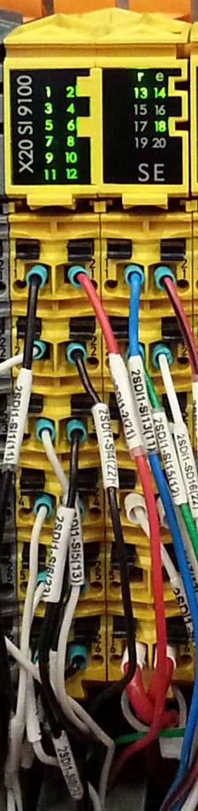
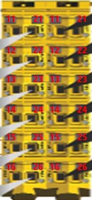
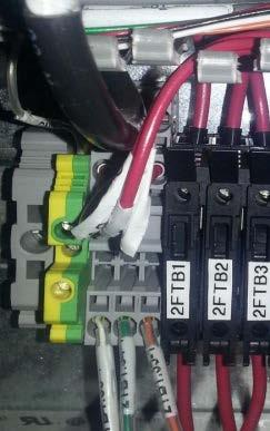
3 Recommended Actions The bridge front door is open 1. Close the hood and ensure it is fully closed 2. Press the Reset (blue) button on the operator console. During the Reset process, the blue LED will blink. 3. Tap Get Ready to continue. The bridge front door interlock is not properly aligned 1. Check the interlock and ensure it is firmly attached to the printer together with its bracket. 2. Check the orientation of both parts of the interlock and ensure they are aligned with each other. 3. Check the distance between the two interlock parts and ensure they are between 0-3 mm. WARNING! High Voltage System! Do not touch any wiring while system is UP! From this stage and on, only an HP certified electrician may perform the tests. The interlock or cable CX connecting it to the B&R module are faulty 1. To verify that the module distributes pulses to the TBM distribution block, check TP 15 and TP25 voltage via 24V_gnd (24V_0). You should get 8-20V. If this is the case continue to the next step. Getting 0V indicates that the entire module is faulty and must be replaced. Note: For redundancy reasons, the 2SDI2 B&R module that receives 24V distributes them as 24V pulses along the route: pins 15, 16, 25, 26 TBMs interlocks B&R module inputs. Therefore, measuring voltage along this route will result in 8-20V. 2. Check the cable connecting the interlock to the B&R module [CX ] and ensure its wires are properly connected to the B&R and that its connector on the interlock side is firmly attached and not damaged. 3. Go to the REC cabinet and check LEDs SI 17 and SI 18 on the 2SDI2 B&R safety module. They should display as shown below 3

 white wire from the B&R module and the 2TBM-6(2) brown wire from the TBM block and check their continuity.")
4 Door closed correct state Door open correct state 4. If the LEDS do not behave as shown above, this might indicate one of three: The two parts of the interlock are not aligned The cable is faulty The interlock is faulty Receiver Transmitter 5. Check the yellow circular cable connecting the receiver to the B&R twice: with the door closed and with the door open. 6. With the door closed, disconnect the 2SDI2-SI17(13) white wire from the B&R module and the 2TBM-6(2) brown wire from the TBM block and check their continuity. You should get continuity between these two test points. 7. With the door open, disconnect the 2SDI2-SI18(23) (blue) wire from the B&R module and the 2TBM-8(2) (black) wire from the TBM block and check their continuity. With the door open you should get continuity between these two test points. 8. If the results correspond to the above, then we know that the yellow circular cable and both parts of the interlock are ok. 9. If the results do not correspond, this might indicate that the interlock receiver is faulty. If this is the case, replace the receiver. 10. If the problem persists even after replacing the receiver, this indicates that the safety B&R module X20 SI9100 is faulty. 4
 and two (12 pins) terminal blocks as shown below.")
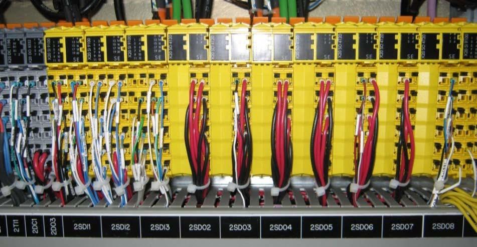
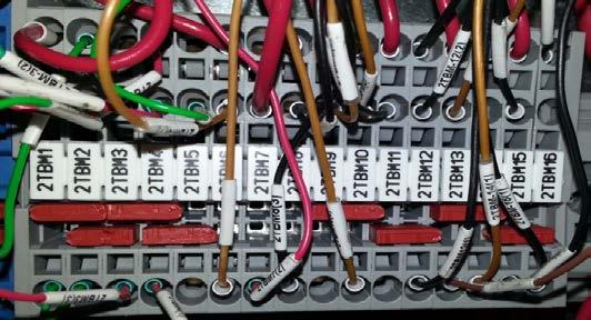
5 The B&R module is faulty 1. Measure 2TBM6(2) and 2TBM8(2) voltage via 24V_gnd (24V_0). You should get 8-20V this means that the entire route is ok and that the module is faulty. 2. As a last check before replacing the module, ensure that the wires between the pulse outputs and the 2TBM distribution block are properly attached. Note: Each B&R Safety module comprises three components: Base, BU (Bus Unit) and two (12 pins) terminal blocks as shown below. When a B&R module is detected as faulty, only its Bus Unit which is the heart of the module must be replaced. 3. Before replacing a B&R module, turn the machine power OFF. 4. Release the two TBs with their wires, as shown in the figure below. 5. Pull the BU out of the module base and replace it by a new one. 6. Plug the two TBs back into the new Bus unit you just installed until you hear a click. Upon turning on the machine, the R/E led will blink green single pulse, signaling that it has detected the new module. 5
 into its base (4). Step 4: Plug the two TBs (2) back into the BU (3) until you hear a click. 7.")
 and press the Enter button to instruct the Safety PLC to configure the new module.")
6 Step 1: Press the two latches (1) on top of the two TBs (2) and unplug them from the faulty BU. Step 2: Press the two latches (5) on top of the module BU (3) and unplug it from its base (4). Step 3: Plug the new BU (3) into its base (4). Step 4: Plug the two TBs (2) back into the BU (3) until you hear a click. 7. Turn the machine on and configure the B&R Safety PLC to recognize and set the new module(s) as described below. 8. Set the Safety PLC selector to 1 (one new module) and press the Enter button to instruct the Safety PLC to configure the new module. Upon completion, the MXCHG LED will blink orange single pulse and then will turn off to confirm that the module was configured. Note: This procedure takes up to two minutes. However, when the PLC encounters internal errors, it runs a full system scan and resets the entire system. This procedure takes between 40 to 60 minutes. 6
7 9. If the MXCHG LED continues blinking orange single pulse every 5 seconds, this indicates that the PLC failed to configure the new module (in case of 2 replaced modules, it will blink twice every 5 seconds etc.). Check if you have set the scan selector according to the number of new modules. Note: Interchanging two existing modules will be detected by the Safety PLC as two new modules. 10. If the MXCHG LED continues blinking orange single pulse every 5 seconds, please consult the detailed B&R PLC configuration guide, on page 4 for further instructions. 11. If none of the above steps solved the problem, contact your HP service specialist. Note: The diagram in the page below shows the tested components and provides a legend of the B&R naming conventions. 7


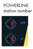
8 B&R Safety Processor - PLC Configuration link is set as Station 6 2 S DI 2 SI 19 (14) 8
FB10000 Error Messages Troubleshooting
 Error ID: 67019: Safety - Front manual loading flap is down Error Severity: Critical Possible Causes Front manual loading flap is down Interlocks connecting flap are misaligned Interlock is faulty or cable
DX-10 tm Digital Interface User s Guide
 DX-10 tm Digital Interface User s Guide GPIO Communications Revision B Copyright Component Engineering, All Rights Reserved Table of Contents Foreword... 2 Introduction... 3 What s in the Box... 3 What
Film-Tech. The information contained in this Adobe Acrobat pdf file is provided at your own risk and good judgment.
 Film-Tech The information contained in this Adobe Acrobat pdf file is provided at your own risk and good judgment. These manuals are designed to facilitate the exchange of information related to cinema
LIGHT AIR SWITCH. User Manual and Troubleshooting Guide WIRELESS LIGHTING MODULE ACKNOWLEDGEMENTS SAFETY WARNINGS EQUIPMENT DESCRIPTION
 WIRELESS LIGHTING MODULE LIGHT AIR SWITCH User Manual and Troubleshooting Guide ACKNOWLEDGEMENTS P2 SAFETY WARNINGS EQUIPMENT DESCRIPTION P2 P2 1 ACCESSORIES/ASSOCIATED PARTS TECHNICAL CHARACTERISTICS
Quick Start Guide Operators
 Projector Components Left Side Cover Rear Cover High voltage and strong UV radiation is present in these projectors! To prevent personal injury, electrical shock, exposure to UV radiation and fire hazard,
MANUAL ENGLISH Core Club Ordercode: D2314
 MANUAL ENGLISH Core Club Ordercode: Highlite International B.V. Vestastraat 2 6468 EX Kerkrade the Netherlands Table of contents Warning... 2 Unpacking Instructions... 2 Safety Instructions... 2 Operating
Introduction. The Spectacle Light Kit makes it easy to illuminate your next project at the push of a button!
 Introduction The Spectacle Light Kit makes it easy to illuminate your next project at the push of a button! Spectacle Light Board The Spectacle Light Board allows you to add some fairly complex lighting
DLP200M 2 Relay Module for Heating and Cooling Plants
 Product Sheet TH6.24 Thermostat Type DLP200M DLP200M 2 Relay Module for Heating and Cooling Plants The DLP 200 M is a relay module for activation of loads (namely thermal actuators or circulators) in wireless
TP HDMI OVER ANYWIRE TRANSMITTER
 HDMI OVER ANYWIRE TRANSMITTER Welcome! Everyone at Altinex greatly appreciates your purchase of the TP315-101. We are confident that you will find it to be reliable and simple to use. If you need support,
Operating instructions Through-beam sensor. OJ51xx laser / / 2010
 Operating instructions Through-beam sensor OJ5xx laser 70480 / 00 05 / 200 Contents Preliminary note. Symbols used 2 Safety instructions Functions and features 4 4 Installation 4 5 Electrical connection5
GuardPLC Certified Function Blocks -- Basic Suite
 GuardPLC Certified Function Blocks -- Basic Suite Catalog Number 753-CFBBASIC Safety Reference Manual Important User Information Solid state equipment has operational characteristics differing from those
DLP600M 6+1 Relay Module for Heating and Cooling Plants
 Product Sheet TH6.25 Thermostat Type DLP600M DLP600M 6+1 Relay Module for Heating and Cooling Plants The DLP 600 M is a relay module for activation of loads (namely thermal actuators or circulators) in
QUICK START GUIDE FLEXSLICE MODULES
 TECHNOLOGY POWER ETHERCAT OUT ETHERCAT IN STATUS LED S POWER AND I/O STATUS LED S USER TAB EBUS CONNECTOR LOCK QUICK START GUIDE FLEXSLICE MODULES P366 P371 P372 P375 P376 P377 P378 P379 description The
Operating instructions Retro-reflective sensor. OJ50xx laser / / 2010
 Operating instructions Retro-reflective sensor OJ50xx laser 70481 / 00 05 / 010 Contents 1 Preliminary note3 1.1 Symbols used 3 Safety instructions 3 4 Installation 4 4.1 Installation of the supplied mounting
Media Tube HO ActionPad Configuration Manual V0.2 User Version
 Media Tube HO Media Tube HO ActionPad Configuration Manual V0.2 User Version Cover: Media Tube HO RGBW/RGB/White Direct View Media Tube HO RGBW/RGB/White Diffused CONTENT 1. INTRODUCTIOn 3 2. Connection
Introduction 1. Green status LED, controlled by output signal ST. Sounder, controlled by output signal Q6. Push switch on input D6
 Introduction 1 Welcome to the GENIE microcontroller system! The activity kit allows you to experiment with a wide variety of inputs and outputs... so why not try reading sensors, controlling lights or
TeamWork Kits Installation Guide
 TX 0 RX COM +5V APARATUS US TeamWork Kits Installation Guide TeamWork 400 and TeamWork 600 Kits The TeamWork 400 and TeamWork 600 kits consist of an HDMI switcher, system controller, Cable Cubby, and cables
12.1 Inch CGA EGA VGA SVGA LCD Panel - ID #492
 12.1 Inch CGA EGA VGA SVGA LCD Panel - ID #492 Operation Manual Introduction This monitor is an open frame LCD Panel monitor. It features the VESA plug & play system which allows the monitor to automatically
Lawnbott No Signal /Blackout Troubleshooting Guide
 The Lawnbott No Signal error can be the most difficult problem to resolve. There are two types of No Signal errors, persistent and intermittent. Persistent means the Lawnbott display shows No Signal as
Contents. Introduction Troubleshooting Techniques... 4 Preparation... 4 Knowledge:... 4 Tools:... 5 Spare Parts:... 5 Backups:...
 Contents Introduction... 3 Troubleshooting Techniques... 4 Preparation... 4 Knowledge:... 4 Tools:... 5 Spare Parts:... 5 Backups:... 5 Troubleshooting Steps... 6 Step 1: Identify the Specific Symptoms:...
CONTENTS. Troubleshooting 1
 CONTENTS Introduction...3 Troubleshooting Techniques...3 Preparation...3 Knowledge...3 Tools...4 Spare Parts...4 Backups...4 Troubleshooting Steps...5 Step 1: Identify the Specific Symptoms:...5 Step 2:
TP HDMI OVER ANYWIRE RECEIVER (DC)
") HDMI OVER ANYWIRE RECEIVER (DC) Welcome! Everyone at Altinex greatly appreciates your purchase of the TP315 106. We are confident that you will find it to be reliable and simple to use. If you need support,
HDMI OVER ANYWIRE RECEIVER (DC) Welcome! Everyone at Altinex greatly appreciates your purchase of the TP315 106. We are confident that you will find it to be reliable and simple to use. If you need support,
Troubleshooting CS800/LC900 Bikes
 Troubleshooting CS800/LC900 Bikes CS800/900LC Bike Troubleshooting Entering the Maintenance Mode 15 Touch Screen: The Maintenance Mode is designed to help the tech determine certain faults in the upper
CAUTION RISK OF ELECTRIC SHOCK NO NOT OPEN
 Evolution Digital HD Set-Top Box Important Safety Instructions 1. Read these instructions. 2. Keep these instructions. 3. Heed all warnings. 4. Follow all instructions. 5. Do not use this apparatus near
Contents: 1 LANsmart Pro Main Unit 4 Remote Unit: ID1, ID2, ID3, ID4
 LANsmart Pro user manual Introduction LANsmart Pro is a hand-held, multifunction Cable Map Tester and Cable Length Meter. It has an integrated Analog and Digital Tone Generator, Port Finder, and Quick
Revision 1.2d
 Specifications subject to change without notice 0 of 16 Universal Encoder Checker Universal Encoder Checker...1 Description...2 Components...2 Encoder Checker and Adapter Connections...2 Warning: High
SELF-INSTALLATION GUIDE
 SELF-INSTALLATION GUIDE Welcome to FrontierTV You are just a few quick connections away from the most amazing TV experience you ve ever had. The colors are stunning and the sound is astonishing. Just follow
Lab 23 Controller Diagnostics
 Lab 23 Controller Diagnostics Name(s) Read the handout titled Controller Area Network (CAN) Theory of Operation Also read in your textbook pages 354 356 to Answer these questions: 1) Why are the Can High
USER MANUEL. SNIPE 2 Ref R13
 USER MANUEL SNIPE 2 Ref. 0141317R13 Contents 1. General Information 1-1. Introduction 1-2. Proper use and operation 1-3. Safety notes......... 2 3 3 2. Contents 2-1. Accessory included 2-2. Name of parts......
HD Digital Set-Top Box Quick Start Guide
 HD Digital Set-Top Box Quick Start Guide Eagle Communications HD Digital Set-Top Box Important Safety Instructions WARNING TO REDUCE THE RISK OF FIRE OR ELECTRIC SHOCK, DO NOT EXPOSE THIS PRODUCT TO RAIN
HC20 Healthcare Kit Installation Instructions
 Our HC20 installation kit uses technology that allows a standard hospital pillow speaker to control a TV and receive audio from the TV at the pillow speaker next to the patient. The HC20 product, when
Safety Information. Camera System. If you back up while looking only at the monitor, you may cause damage or injury. Always back up slowly.
 Table of Contents Introduction...3 Safety Information...4-6 Before Beginning Installation...7 Installation Guide...8 Wiring Camera & Monitor...9-10 Replacement Installation Diagram...11 Clip-On Installation
Auxiliary states devices
 22 Auxiliary states devices When sampling using multiple frame states, Signal can control external devices such as stimulators in addition to switching the 1401 outputs. This is achieved by using auxiliary
SR - 516D DESK TOP DMX REMOTE STATION. Version: Date: 05/16/2013
 SR - 516D DESK TOP DMX REMOTE STATION Version: 1.10 Date: 05/16/2013 Page 2 of 10 TABLE OF CONTENTS DESCRIPTION 3 POWER REQUIREMENTS 3 INSTALLATION 3 CONNECTIONS 3 POWER CONNECTIONS 3 DMX CONNECTIONS 3
User Manual Color video door phone
 User Manual Color video door phone CDV-70AR3 Thank you for purchasing COMMAX products. Please carefully read this User s Guide (in particular, precautions for safety) before using a product and follow
CONNECTOR A (BLACK 4 PIN) LED S CONNECTOR B (WHITE 4 PIN) CONNECTOR C (WHITE 5 PIN) CONNECTOR D (WHITE 2 PIN) 1x device. 2x - 10x
 LED S CONNECTOR B (WHITE 4 PIN) CONNECTOR C (WHITE 5 PIN) CONNECTOR D (WHITE 2 PIN) 1x device. 2x - 10x") SIC3-RFK FIRMWARE 2.0.4 A B CONNECTOR A (BLACK 4 PIN) TO BYPASS OR REMOTE STARTER LED S CONNECTOR B (WHITE 4 PIN) TO SOLACE ANTENNA ( NOT INCLUDED ) CONNECTOR C (WHITE 5 PIN) GRAY / BLACK - START / STOP
SIC3-RFK FIRMWARE 2.0.4 A B CONNECTOR A (BLACK 4 PIN) TO BYPASS OR REMOTE STARTER LED S CONNECTOR B (WHITE 4 PIN) TO SOLACE ANTENNA ( NOT INCLUDED ) CONNECTOR C (WHITE 5 PIN) GRAY / BLACK - START / STOP
Trusted TMR I/O SmartSlot Slot Cables
 PD-TC500 Trusted Trusted TMR I/O SmartSlot Slot Cables Product Overview This document provides detailed information for the types of Trusted input/output (I/O) Cables available within the SmartSlot group.
GRANT RF CONTROL CENTER INSTALLATION INSTRUCTIONS Always disconnect battery while servicing or modifying the electrical system of the vehicle.
 GRANT RF CONTROL CENTER INSTALLATION INSTRUCTIONS Always disconnect battery while servicing or modifying the electrical system of the vehicle. You will need standard hand tools, a Test Light and a Digital
Spectacle Light Kit Hookup Guide
 Page 1 of 23 Spectacle Light Kit Hookup Guide Introduction The Spectacle Light Kit makes it easy to illuminate your next project at the push of a button! Spectacle Light Kit KIT-14170 Suggested Reading
User Manual. Color video door phone CDV-70P PM0770P Printed In Korea /
 User Manual Color video door phone CDV-70P 513-11, Sangdaewon-dong, Jungwon-gu, Seongnam-si, Gyeonggi-do, Korea 513-11, Sangdaewon-dong, Jungwon-gu, Seongnam-si, Gyeonggi-do, Korea Business Dept. : +82-31-7393-540~550
FS3. Quick Start Guide. Overview. FS3 Control
 FS3 Quick Start Guide Overview The new FS3 combines AJA's industry-proven frame synchronization with high-quality 4K up-conversion technology to seamlessly integrate SD and HD signals into 4K workflows.
FOREST SHUTTLE S / L / M RECEIVER
 2 FOREST SHUTTLE S / L / M RECEIVER QUICK INSTALLATION OF ASSEMBLED TRACKS : Programming Shuttle S / L / M Receiver to a channel One pre-assembled motorized curtain track systems is standard programmed
Installation Guide. Cellular Plug-in for Inverters with SetApp. Version 1.1
 Installation Guide Cellular Plug-in for Inverters with SetApp Version 1.1 2 Version History Version 1.0 (initial release)- January 2019 Version 1.1- January 2019 Modified Technical Specifications modem
 Switch Panel Backlight Issues (white backlighting that illuminates the label text) Notes: the backlighting is controlled by a 'PANEL LIGHTS' button at the Galley 8 button switch panel) Backlighting is
CU103 User Manual. Contents
 [Note] The Photos of Light Engine and Control Unit in this manual are for reference only. The items may be different in actual package. Contents 1. PRECAUTIONS... 2 2. PACKAGE CONTENT... 4 3. PORT DESCRIPTION...
AW900mT. User s Manual. Point-to-multipoint. Industrial-grade, ultra-long-range 900 MHz non-line-of-sight wireless Ethernet systems
 User s Manual Point-to-multipoint Industrial-grade, ultra-long-range 900 MHz non-line-of-sight wireless Ethernet systems User s Manual Non-line-of-sight :: 900 MHz Thank you for your purchase of the multipoint
What is SnoCam? SnoCam Installation Guide. SolarVu
 4 1 2 3 4 5 6 7 8 D+ Rx- GND V+ GND V+ Power 1 2 3 4 5 6 7 8 9 10 What is? SolarVu Installation Guide SolarVu is an energy portal that enables remote monitoring of renewable energy generation sites over
Solutions to Embedded System Design Challenges Part II
 Solutions to Embedded System Design Challenges Part II Time-Saving Tips to Improve Productivity In Embedded System Design, Validation and Debug Hi, my name is Mike Juliana. Welcome to today s elearning.
Easyl Installation and Programming Manual. EasylTM Solo. Easyl DMX Controller. Easyl is for RGB LED fixtures with DMX control input.
 TS-EASYL-001 Installation and Programming Manual Installation and Programming Manual TM Solo DMX Controller is for RGB LED fixtures with DMX control input January 19, 2013 800.922.9646 2013 Acuity Brands
Warning and Safety Information. FCC Information
 Installation Manual Warning and Safety Information FCC Information This device complies with FCC Rules Part 15 Operation and is subject to the following two conditions: (1) This device may not cause harmful
Introduction Display...1 Mounting...1 Firmware Version...2. ADL Operation... 3
 MoTeC MDD User Manual Contents Introduction... 1 Display...1 Mounting...1 Firmware Version...2 ADL Operation... 3 1. Full ADL Display...4 2. Gain Loss Layout for ADL...6 3. Large Numeric Layout for ADL...8
Configuration Vestas VMP3500
 Configuration Vestas VMP3500 1. Table of contents 1. Table of contents... 2 2. Introduction... 3 3. Vestas turbines (RCS)... 4 3.1. VMP 3500 controller... 4 3.2. Communication with the CT3230 current loop
Evolution Digital HD Set-Top Box Important Safety Instructions
 Evolution Digital HD Set-Top Box Important Safety Instructions 1. Read these instructions. 2. Keep these instructions. 3. Heed all warnings. 4. Follow all instructions. 5. Do not use this apparatus near
DE2-115/FGPA README. 1. Running the DE2-115 for basic operation. 2. The code/project files. Project Files
 DE2-115/FGPA README For questions email: jeff.nicholls.63@gmail.com (do not hesitate!) This document serves the purpose of providing additional information to anyone interested in operating the DE2-115
PACSystems* RX3i Thermocouple Input Module, 12 Channels, IC695ALG412-CB
 September 2013 PACSystems* RX3i Thermocouple Input Module, 12 Channels, IC695ALG412-CB The PACSystems * Thermocouple Input module IC695ALG412 provides twelve isolated differential thermocouple input channels.
Dual PAL or NTSC Video to RGB Converter (One way) with 12V Relay Switch Operation Manual
 with 12V Relay Switch Operation Manual") Dual PAL or NTSC Video to RGB Converter (One way) with 12V Relay Switch Operation Manual Introduction This unit converts video signals from NTSC/PAL/SECAM into RGB/Sync or RGsB (Sync On Green) to allow
Dual PAL or NTSC Video to RGB Converter (One way) with 12V Relay Switch Operation Manual Introduction This unit converts video signals from NTSC/PAL/SECAM into RGB/Sync or RGsB (Sync On Green) to allow
END USER MANUAL DAS-M44HD-R
 END USER MANUAL DAS-M44HD-R Warnings: Important Safety Instructions and Caution Please read all of these instructions regarding your unit and retain them for future reference Read this manual fully and
OSD. EXECUTIVE / MiniDome USERS MANUAL. USING THE MOTOSAT DISH POINTING SYSTEM EXECUTIVE / MiniDome OSD
 EXECUTIVE / MiniDome OSD USERS MANUAL USING THE MOTOSAT DISH POINTING SYSTEM EXECUTIVE / MiniDome OSD MotoSAT Corporation Created April 22, 2003 1-800-247-7486 CONGRATULATIONS! on your purchase of your
Six-Channel TDM Multiplexers for 3G, HD, SDI, and ASI. Installation and Operations. Manual
 Manual DigiLink DLC156 Function modules Six-Channel TDM Multiplexers for 3G, HD, SDI, and ASI Installation and Operations Manual WWW.ARTEL.COM ii DLC156 Function Modules Installation and Operations Manual
ALO 030 MKII. 30 Watt DMX LED scanner. User manual
 ALO 030 MKII 30 Watt DMX LED scanner User manual Safety instructions WARNING! Always keep this device away from moisture and rain! Hazardous electrical shocks may occur! WARNING! Only connect this device
KNX Dimmer RGBW - User Manual
 KNX Dimmer RGBW - User Manual Item No.: LC-013-004 1. Product Description With the KNX Dimmer RGBW it is possible to control of RGBW, WW-CW LED or 4 independent channels with integrated KNX BCU. Simple
ALM-6813/6812 INSTALLATION AND PROGRAMMING MANUAL
 ALM-6813/6812 INSTALLATION AND PROGRAMMING MANUAL Installation and programming Manual v2.2 1 MARSS Solar Defender SYSTEM This guidebook provides the essential instructions to install and configure the
SERCOS TSX CSY 84 Module V
 SERCOS TSX CSY 84 Module V At a Glance Aim of this Part What's in this part? This part presents the SERCOS TSX CSY 84 module, its operating features and its installation. This Part contains the following
HDMI Expander Family EP-HC0408 EP-HC046
 HDMI Expander Family EP-HC0408 EP-HC046 EP-HC0408/EP-HC0416 User Manual Version 1.0 Last Updated: March 2008 Table of Content 3 Notice 4 Package Content 5 Product Introduction 5 Product Features 6 Panel
USER MANUAL FOR CABLE RECEIVER KAON KCF-200CO KAON KCF-H220SCO
 USER MANUAL FOR CABLE RECEIVER KAON KCF-200CO KAON KCF-H220SCO SECURITY INSTRUCTIONS FOR USING THE RECEIVER Always fallow these instructions to avoid risk of injury or damaging the equipment. Before cleaning
15 Inch CGA EGA VGA to XGA LCD Wide Viewing Angle Panel ID# 833
 15 Inch CGA EGA VGA to XGA LCD Wide Viewing Angle Panel ID# 833 Operation Manual Introduction This monitor is an open frame LCD Panel monitor. It features the VESA plug & play system which allows the monitor
Safety Light Curtains
 4 Safety Light Curtains F3SJ-A Safety Light Curtains Resolution: 14 mm (0.55 in.), 20 mm (0.79 in.), 25 mm (1.01 in.) 30 mm (1.18 in.), or 55 mm (2.17 in.) Range: 7 m (23 ft.) or 9 m (29.5 ft.) dependent
Exercise 5-1. Troubleshooting Techniques EXERCISE OBJECTIVE DISCUSSION OUTLINE DISCUSSION. Signal flow tracing
 Exercise 5-1 Troubleshooting Techniques EXERCISE OBJECTIVE When you have completed this exercise, you will be able to apply a systematic technique of signal flow tracing to diagnose instructor-inserted
4 Channel HD SDI Over Fiber Transmitter and Reciever Extender with RS 485 Channel User Manual L-4SDI-FE-HD-TX/RX
 4 Channel HD SDI Over Fiber Transmitter and Reciever Extender with RS 485 Channel User Manual L-4SDI-FE-HD-TX/RX 1 Contents CHAPTER 1. INTRODUCTION... 2 1.1 OVERVIEW...2 1.2 FEATURE...2 1.3 APPLICATION...3
Be sure to run the vehicle engine while using this unit to avoid battery exhaustion.
 CAUTION: TO REDUCE THE RISK OF ELECTRIC SHOCK DO NOT REMOVE COVER (OR BACK) NO USER-SERVICEABLE PARTS INSIDE REFER SERVICING TO QUALIFIED SERVICE PERSONNE; Please Read all of these instructions regarding
CAT6 Cable Tester. Operating Manual. Part No TRIAX - your ultimate connection
 CAT6 Cable Tester Part No. 157010 Operating Manual TRIAX - your ultimate connection Application For checking CAT 5e and CAT 6 cables, (UTP and STP). Can also be used with BNC coaxial cable and modular
LS 5.0R SERVICE MANUAL
 LS 5.0R SERVICE MANUAL 1 TABLE OF CONTENTS CHAPTER 1: SERIAL NUMBER LOCATION CHAPTER 2: CONSOLE OVERLAY AND WORKOUT DESCRIPTION 2.1 Console Description 2.2 Display Windows Description 2.3 Getting Started
User Manual PS-684. HDBaseT Extender Kit 70m. All Rights Reserved. Version: UHBT70P_2016V1.2
 User Manual PS-684 All Rights Reserved Version: UHBT70P_2016V1.2 Preface Read this user manual carefully before using this product. Pictures shown in this manual is for reference only, different model
FACTORY AUTOMATION AS-INTERFACE MAINTENANCE AND TROUBLESHOOTING GUIDE
 FACTORY AUTOMATION AS-INTERFACE MAINTENANCE AND TROUBLESHOOTING GUIDE Table of Contents AS-Interface Basics... 3 Addressing Modules... 4 Handheld Programmer (Reading Inputs and Settings Outputs)... 5 Gateway
Platinum Tools Inc. All rights reserved. 5/12 Voice, Data, Video + Length GENERAL SPECIFICATIONS WARNINGS
 Voice, Data, Video + Length Instruction Sheet: P/N T9 GENERAL SPECIFICATIONS The Platinum Tools, VDV MapMaster.0 is a portable voice-data-video cable tester with length measurement. It tests and troubleshoots
Trusted 40 Channel 120 Vac Digital Input FTA
 ICSTT-RM290F-EN-P (PD-T8824) Trusted Product Overview The Trusted 40 Channel 120 Vac Digital Input Field Termination Assembly (FTA) T8824 is designed to act as the main interface between a field device
Your Global Automation Partner. Ultrasonic Sensors. Operating Instructions
 Your Global Automation Partner RU CK40 RU CP40 Ultrasonic Sensors Operating Instructions Contents 2 Hans Turck GmbH & Co. KG T +49 208 4952-0 F +49 208 4952-264 more@turck.com www.turck.com Contents 1
Spectacle Motion Board Hookup Guide
 Page 1 of 16 Spectacle Motion Board Hookup Guide Spectacle Motion Board The Spectacle Motion Board makes it easy to add movement to your Spectacle projects. It can control up to 5 servo motors, either
CN Remove the scanner assembly (X476 and X576 models) and all doors/covers.
 and all doors/covers.") CN598-67045 www.hp.com/support IMPORTANT: Ensure the product firmware is upgraded to at least version 1336MR before performing this repair procedure. If the firmware upgrade cannot be completed, contact
CN598-67045 www.hp.com/support IMPORTANT: Ensure the product firmware is upgraded to at least version 1336MR before performing this repair procedure. If the firmware upgrade cannot be completed, contact
Remote Control. degraded, causing unreliable operation. The recommended effective distance for remote operation is about 16 feet (5 meters).
.") Media Streaming Sound Bar RTS736W User Manual Remote Control using the remote control Point the remote control at the REMOTE SENSOR located on the unit (see Front Panel illustration for precise location).
Media Streaming Sound Bar RTS736W User Manual Remote Control using the remote control Point the remote control at the REMOTE SENSOR located on the unit (see Front Panel illustration for precise location).
Troubleshooting. 1. Symptom: Status indicator (Red LED) on SSR is constant on. 2. Symptom: Output indicator (Yellow LED) on SSR is flashing.
 on SSR is constant on. 2. Symptom: Output indicator (Yellow LED) on SSR is flashing.") Product Data Electrical Data SST (Transmitter) SSR (Receiver) Supply voltage 18 30 V dc Max. Voltage ripple 15 % (within supply range) Current consumption 100 ma (RMS) 75 ma Digital - 100 ma Max. outputs
Product Data Electrical Data SST (Transmitter) SSR (Receiver) Supply voltage 18 30 V dc Max. Voltage ripple 15 % (within supply range) Current consumption 100 ma (RMS) 75 ma Digital - 100 ma Max. outputs
Trusted 40 Channel 120 Vac Digital Input FTA
 PD-T8824 Trusted Trusted 40 Channel 120 Vac Digital Input FTA Product Overview The Trusted 40 Channel 120 Vac Digital Input Field Termination Assembly (FTA) T8824 is designed to act as the main interface
Setting up the Setting up the Dragonfly 1 v June
 Setting up the 1 Introduction In this guide we'll be setting up a rather complete observatory, integrating in the Dragonfly all relevant elements: Roof, motorized with a garage-door system and including
PLL1920M LED LCD Monitor
 PLL1920M LED LCD Monitor USER'S GUIDE www.planar.com Content Operation Instructions...1 Safety Precautions...2 First Setup...3 Front View of the Product...4 Rear View of the Product...5 Installation...6
X D M PREAMP MIXER
 User Instructions X D M - 3 5 2 PREAMP MIXER Thank you for purchasing this American DJ product. The XDM-352 is ready to be used, there is no assembly required. Please read the following instructions before
Vision Sensor Short Manual
 Vision Sensor FQ Short Manual Cat. No. Z306-E1-02A Table of Contents 1. Introduction 1-1 FQ-series Vision Sensors....................................... 4 1-2 Measurement Process.........................................
Smart Control SC16 3-Channel for matrix
 Operating Manual Smart Control SC16 3-Channel for matrix Dear Customer, Thank you for choosing a WALTRON daytime lighting controller. Your daytime lighting controller is a high-quality product that was
Instruction Manual. 2.4G Digital Wireless Four Channel Transmitter System RVS-554W. Reverse With Confidence 1
 Instruction Manual 2.4G Digital Wireless Four Channel Transmitter System RVS-554W 1 NOTE! Please read all of the installation instructions carefully before installing the product. Improper installation
3. Electronics and MMU2 unit assembly
 Written By: Jakub Dolezal 2018 manual.prusa3d.com/ Page 1 of 34 Step 1 Tools necessary for this chapter Please prepare tools for this chapter: 2.5mm Allen key for M3 screws 2mm Allen key for nut alignment
Original BMW Accessory. Installation Instructions.
 Original BMW Accessory. Installation Instructions. ipod Interface Retrofit BMW 5 Series (E 60, E 6) BMW 6 Series (E 63, E 64) These installation instructions are only valid for cars without SA 67 (CD changer)
FS4 Quick Start Guide
 FS4 Quick Start Guide Overview FS4 is AJA s flagship frame synchronizer and converter, offering incredible versatility and connectivity in a sleek and compact 1RU frame for all your 4K/ UltraHD/2K/HD/SD
SCREEN WINCH SYSTEM INSTALLATION MANUAL FOR SCREENS UP TO 300 cm. of width
 SCREEN WINCH SYSTEM INSTALLATION MANUAL FOR SCREENS UP TO 300 cm. of width Before installing the screen winch system, please read the following instructions carefully: The screen winch system must be used
12months. on-site warranty. DZE ELECTRONIC PRESSURE SWITCH for detection of overload per EN 81 2 featuring two adjustable switching points
 BUCHER PRODUCTS AVAILABLE FROM HYDRATEC DZE ELECTRONIC PRESSURE SWITCH for detection of overload per EN 81 2 featuring two adjustable switching points 12months on-site warranty All our work comes with
Quick Reference Guide
 Multimedia Projector Quick Reference Guide MODEL 103-011100-01 Projection lens is optional. English Use this book as a reference guide when setting up the projector. For detailed information about installation,
Intellivision Master Component Owner's Manual
 Intellivision Master Component Owner's Manual CONTENTS How to Connect the Antenna Switchbox Set Up Your Master Component How to Insert the Cartridge How to Use the Master Component The Intermission Code
EXT-HBT70-SET_2016V1.2
 USER MANUAL EXT-HBT70-SET HDBaseT Extender Set 70m All Rights Reserved Version: EXT-HBT70-SET_2016V1.2 Preface Read this user manual carefully before using this product. Pictures shown in this manual is
PASS. Professional Audience Safety System. User Manual. Pangolin Laser Systems. November 2O12
 PASS Professional Audience Safety System User Manual November 2O12 Pangolin Laser Systems Downloaded from the website www.lps-laser.com of your distributor: 2 PASS Installation Manual Chapter 1 Introduction
Hi! Let s get started.
 Hi! Let s get started. What s in the box Roku 2 player Roku 2 enhanced remote Headphones 2 x AA batteries for remote A/V cable (RCA) Power adapter Get to know your Roku 2 A Front view B E Back view C
Be sure to check the camera is properly functioning, is properly positioned and securely mounted, every time you operate your vehicle.
 Please read all of the installation instructions carefully before installing the product. Improper installation will void manufacturer s warranty. The installation instructions do not apply to all types
S Regulators. Supplement 1. Contents. Control Replacement Assembly Installation Instructions Supplement
 Regulators Control Replacement Assembly Installation Instructions Supplement Service Information S225-40-1 Supplement 1 Figure 1. CL-6A Control Replacement Assembly. Contents Safety Information... 2 Product