Safety Information. Camera System. If you back up while looking only at the monitor, you may cause damage or injury. Always back up slowly.
|
|
|
- Allison Daniels
- 5 years ago
- Views:
Transcription
1
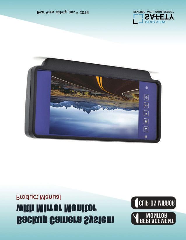
2 Table of Contents Introduction...3 Safety Information Before Beginning Installation...7 Installation Guide...8 Wiring Camera & Monitor Replacement Installation Diagram...11 Clip-On Installation Diagram...12 Installing The Monitor...13 Monitor Operation Splitting & Splicing...15 Positioning...16 Multiplexer...17 Monitor Dimensions...18 Monitor Specifications...19 Troubleshooting...20
3 Introduction Congratulations on purchasing a Rear View Backup Camera System! With this manual you will be able to properly install and operate the unit. Please read all of the installation instructions carefully before installing the product. Improper installation will void manufacturer s warranty. The Backup Camera System is intended to be installed as a supplement aid to your standard rear view mirror that already exists in your vehicle. The Backup Camera System should not be used as a substitute for the standard rear view mirror or for any other mirror that exists in your vehicle. In some jurisdictions, it is unlawful for a person to drive a motor vehicle equipped with a TV viewer or screen located forward of the back of the driver s seat or in any location that is visible, directly or indirectly, to the driver while operating the vehicle. 3
4 Safety Information Please read the entire manual and follow the instructions and warnings carefully. Failure to do so can cause serious damage and/or injury, including loss of life. Be sure to obey all applicable local traffic and motor vehicle regulations as it pertains to this product. Improper installation will void manufacturer s warranty. USAGE The Rear View Camera System is designed to help the driver safely detect people and/or objects helping to avoid damage or injury. However, you the driver, must use it properly. Use of this system is not a substitute for safe, proper or legal driving. Never back up while looking at the monitor alone. You should always check behind and around the vehicle when backing up, in the same way as you would if the vehicle did not have the Rear View Camera System. If you back up while looking only at the monitor, you may cause damage or injury. Always back up slowly. The Rear View Camera System is not intended for use during exstensive back-up maneuvers or backing into cross traffic or pedestrian walkways. Please, always remember, the area displayed by the Rear View Camera System is limited. It does not display the entire panorama that is behind you. 4 REAR VIEW SAFETY
5 Safety Information INSTALLATION Electric shock or product malfunction may occur if this product is installed incorrectly. Use this product within the voltage range specified. Failure to do so can cause electronic shock or product malfunction. Take special care when cleaning the monitor. Make sure to firmly affix the product before use. If smoke or a burning smell is detected, disconnect the system immediately. Where the power cable may touch a metal case, cover the cable with a friction tape. A short circuit or disconnected wire may cause a fire. Reverse With Confidence While installing the RVS System be careful with the wire positioning in order to avoid wire damage. The RVS System should only be used when the vehicle is in reverse. Do not watch movies or operate the monitor while driving; as it may cause an accident. Do not install the monitor where it may obstruct drivers view or obstruct an air bag device. Dropping the unit may cause possible mechanical failure. 5
6 Safety Information IN NO EVENT SHALL SELLER OR MANUFACTURER BE LIABLE FOR ANY DIRECT OR CONSEQUENTIAL DAMAGES OF ANY NATURE, OR LOSSES OR EXPENSES RESULTING FROM ANY DEFECTIVE PRODUCT OR THE USE OF ANY PRODUCT. 6 REAR VIEW SAFETY
7 Before You Begin Installation Before drilling please check that no cable or wiring is on the other side of the wall. Please clamp all wires securely to reduce the possibility of them being damaged while vehicle is in use. Keep all cables away from hot or moving parts and electrical noisy components. We recommend doing a benchmark test before installation to insure that all components are working properly. Step 1: Choose the monitor and camera locations. Step 2: Install all cables in vehicle, when necessary a 0.8 (20mm) hole should be drilled for passing camera cable through vehicles walls. Install split grommets where applicable. Step 3: Once all cables and wiring have been properly routed, perform a system function test by temporarily connecting the system. If the system seems to not be operating properly see troubleshooting (page 20). Reverse With Confidence 7
8 Installation Guide Cable 1. Be sure to position the cable properly. The aviation camera cable uses aircraft grade connectors which means the camera cable can be exposed to all weather elements. Do not run the cable over sharp edges, do not kink the cable and keep away from HOT and rotating parts. 2. Fasten all cables and secure all excess cable. Replacement Monitor 1. The Mirror Monitor replaces the existing rear view mirror in vehicle. 2. Replace existing mirror, and adjust mounting angle to allow optimum driver viewing comfort. (see figure 1.1 on page 11). Clip-On Monitor 1. The Mirror Monitor attaches to the existing rear view mirror in vehicle with the pressurized clips on the back of the monitor. 2. Attach monitor to existing miror, and adjust mounting angle to allow optimum driver viewing comfort. (see figure 1.1 on page 12). 8 REAR VIEW SAFETY
9 Wiring Camera & Monitor The multiplexer. To power the system connect the power (RED) 12V+ wire to ignition power and the ground (BLACK) wire to chassis ground. These are the only wires needed to power the entire system and all the cameras. Each camera can be seen at any time by simply pressing the power button and using the V1/2 button to toggle. The three positive trigger wires (BLUE-CH1, WHITE-CH2, YELLOW-CH3) each represent one channel and will turn on their channel when the trigger wire is energized with 12V. "Camera 3" is the designated backup channel. To have the the backup camera come on when you go into reverse, connect the BLUE wire to reverse power (or any power source that comes on only in reverse). The other channels can similarly be triggered (i.e. side cameras can be triggered by the turn signals etc.) To automatically have camera and monitor turn ON when vehicle activates, simply twist BLUE positive trigger 12V+ to Red Power line 12V+ and wire to ignition power. Note: This setup will disable the menu in channel 3. To access the menu simply move to channel 1 or 2 and all the changes will apply to channel 3. Note: When the blue wire is active it will have precedence over the other triggers. Therefore, if you wish to use multiple triggers, do not attach the blue trigger to constant power. Reverse With Confidence 9
10 Wiring Camera & Monitor Audio: There is audio on channels 2 and 3. On channel 3 the blue trigger wire must be energized (12V) to activate the audio. On channel 2 the audio is always on. Grid-lines: The grid-lines are also carried through the blue wire. To use the grid-lines for reversing, connect the blue wire to a reverse power. There is a built-in voltage regulator for our systems which can handle volts. Real consumption is 10 to 30 Volts. Note: The camera and monitorcan always be activated by manually pushing the power button on monitor. This is in addition to utilizing the positive triggers. Note: If connecting power directly to battery, the camera is always ON and therefore can drain battery. Therefore it is recommended to connect power to an ignition switched accessory power source. 10 REAR VIEW SAFETY
11 Replacement Installation Diagram Replacement Monitor Figure 1.1 Figure 1.2 Figure 1.3 Reverse With Confidence 11
12 Clip-On Installation Diagram Clip-On Monitor Figure 1.1 Figure 1.2 Figure REAR VIEW SAFETY
13 Installing the Monitor 66ft Extension Cable Monitor Video Out -3 Amp Fuse Multiplexer Optional Camera Available 1. DC12V-24V (red) 2. Ground (black) 3. Port #3 (blue) 4. Port #2 (white) 5. Port #1 (yellow) Reverse With Confidence 13


14 Monitor Operation UP MENU DOWN V1/V2 ON/OFF Brightness, Contrast, Saturation, Sharpness: Adjust image properties Picture Adjust: Stretch image horizontally (right/left and left/right) Turn: Toggle between mirror/normal image on each individual channel Name: Change name of teach individual channel Trigger Delay: Adjust time delay on each trigger Trigger Source: Toggle channel destination for each trigger Distance Grid: Toggle which channel distance grid lines will display on Grid Position: Adjust position of distance grid lines Auto Power: On: Monitor will automatically turn on when powered. Off: Monitor will only turn on when triggered. Auto: Monitor will follow previous state. Reset: Reset settings to factory default 14 REAR VIEW SAFETY
15 Splicing Red - Power (+) 2. Yellow - Video 3. Green - Mirror / Normal Imaging 4. White - Audio 5. Black - Ground (-) Reverse With Confidence 15

16 Positioning General Installation Location 16 REAR VIEW SAFETY

17 Multiplexer (select cameras only) Port #1 Port #2 Port #3 or DVD Backup Reverse With Confidence 17


18 Monitor Dimensions Replacement Monitor Clip-On Monitor 18 REAR VIEW SAFETY
19 Monitor Specifications TFT LCD Digital Monitor Screen Size Digital 7 Dot Resolution 800H x 3 (RGB) x 480V Display Format 16:9 Display Brightness 400cd/m 2 Viewing Angle 90 min Video Input 3 channel Video Source 1Vp-p, 75Ω Power Supply DC 12V-24V (+/-10%) Power Consumption 5W Operating Temperature -10 C C Video System Auto NTSC/PAL Overall Dimensions 9 L x 4.5 H x 1 D Weight 400G Impact Rating 5G Dot Pitch 0.192H x V Sync System Internal Reverse With Confidence 19
20 Troubleshooting Monitor Displays Blue Screen & Displays No Signal Do a hard reset, unplug all cables and power cables from multiplexer (silver box) leave out for 1 minute and then re-connect them. Check to ensure that the connection to the camera is tight. Verify camera cable is plugged into port labeled Backup Camera Verify that the blue positive trigger on power harness is put to power 12v+. If the problem still persists, verify that alternate ports work. If alternate ports do not work, remove Blue Trigger wire from 12V+ and select alternate channels. Monitor Will Not Power-Up (no backlight on power button) Check fuse Check 12v+ to monitor Check ground connection Verify camera is in correct camera input Verify cable is connected to monitor Verify camera is connected to cable Verify chosen camera has audio Verify volume setting 20 No Image On Screen Audio on Camera (optional) Connect known working camera and cable to monitor. Verify Blue trigger is receiving power Confirm that the Blue audio trigger is connected to 12v+ REAR VIEW SAFETY
What s in the Box? RVS SYSTEMS
 TM 1 What s in the Box? 1 Color CCD Infra-red Weather Proof Camera 1 7" LED Color Monitor w/universal Mount/Stand & Wire 1 3 Channel Multiplexer Control Unit 1 66 Camera Cable 1 Remote Control 1 Power
Instruction Manual. 7" Wireless Camera System with Wired Side Camera Inputs RVS-355W. Reverse With Confidence 1
 Instruction Manual 7" Wireless Camera System with Wired Side Camera Inputs RVS-355W Reverse With Confidence 1 RVS-355W.indd 1 10/2/2017 3:33:32 PM TABLE OF CONTENTS Introduction..............................
Instruction Manual. 2.4G Digital Wireless Four Channel Transmitter System RVS-554W. Reverse With Confidence 1
 Instruction Manual 2.4G Digital Wireless Four Channel Transmitter System RVS-554W 1 NOTE! Please read all of the installation instructions carefully before installing the product. Improper installation
Phone (440) Fax Wireless Rear Observation System With Night Vision Camera
 Fax Wireless Rear Observation System With Night Vision Camera") www.buyersproducts.com Phone (440) 974-8888 Fax 800-841-8003 8883200 Wireless Rear Observation System With Night Vision Camera 1 Table of Contents What's in the Box?...3 Introduction...4 Safety Information...5-6
www.buyersproducts.com Phone (440) 974-8888 Fax 800-841-8003 8883200 Wireless Rear Observation System With Night Vision Camera 1 Table of Contents What's in the Box?...3 Introduction...4 Safety Information...5-6
1 Split Screen Digital Wireless Monitor with Cigarette Lighter Adaptor 1 CCD Wireless Backup Camera with Power Cable 1 Extendable Suction Cup Mount
 What s in the Box? 1 Split Screen Digital Wireless Monitor with Cigarette Lighter Adaptor 1 CCD Wireless Backup Camera with Power Cable 1 Extendable Suction Cup Mount for Monitor Table of Contents Introduction...4
Instruction Manual. OEM G-Series Backup Camera System with Frameless Mirror Monitor RVS Reverse With Confidence 1
 Instruction Manual OEM G-Series Backup Camera System with Frameless Mirror Monitor RVS-218640 Reverse With Confidence 1 TABLE OF CONTENTS Introduction.............................. 03 Safety Information..............................
Instruction Manual. Wireless Safety Camera System for Forklifts with 5" Dual Screen Display RVS Reverse With Confidence 1
 Instruction Manual Wireless Safety Camera System for Forklifts with 5" Dual Screen Display RVS-655155 Reverse With Confidence 1 TABLE OF CONTENTS Introduction.............................. 03 Safety Information..............................
Be sure to check the camera is properly functioning, is properly positioned and securely mounted, every time you operate your vehicle.
 Please read all of the installation instructions carefully before installing the product. Improper installation will void manufacturer s warranty. The installation instructions do not apply to all types
Model: LCD4WM 3.5 Window Mounted LCD Monitor User Manual Features
 Model: LCD4WM 3.5 Window Mounted LCD Monitor User Manual Features 3.5 High Resolution TFT LCD Monitor Low Profile, Slim Design Fully Adjustable reversing guidelines Built in Speaker Two video inputs Fully
Instruction Manual. Wireless Transmitters (Digital) RVS-550W. Reverse With Confidence 1
 RVS-550W. Reverse With Confidence 1") Instruction Manual Wireless Transmitters (Digital) RVS-550W Reverse With Confidence 1 TABLE OF CONTENTS In The Box 1 x Transmitter 1 x Receiver TABLE OF CONTENTS Table of Contents................................
Instruction Manual Wireless Transmitters (Digital) RVS-550W Reverse With Confidence 1 TABLE OF CONTENTS In The Box 1 x Transmitter 1 x Receiver TABLE OF CONTENTS Table of Contents................................
OWNER S MANUAL MOTORIZED 7 WIDE TFT LCD COLOR MONITOR CNT-701
 OWNER S MANUAL PW MOTORIZED 7 WIDE TFT LCD COLOR MONITOR CNT-701 ANY CHANGES OR MODIFICATIONS IN CONSTRUCTION OF THIS UNIT DEVICE WHICH IS NOT APPROVED BY THE PARTY RESPONSIBLE FOR COMPLIACE COULD VOID
TECHNICAL SUPPORT , or FD151CV-LP Installation and Operation Manual 15.1 Low Profile LCD
 TECHNICAL SUPPORT 678-867-6717, or www.flightdisplay.com FD151CV-LP Installation and Operation Manual 15.1 Low Profile LCD FD151CV-LP 15.1" Low Profile LCD 2006 Flight Display Systems. All Rights Reserved.
VMA573 and VMA or 7 Wide Screen Color LCD Monitor. Owner s Manual. Installation Guide
 VMA573 and VMA773 5.6 or 7 Wide Screen Color LCD Monitor Owner s Manual Installation Guide 7 headrest / stand alone wide monitor 5.6 headrest / stand alone wide monitor 2 WARINING! The Clarion VMA 573
FD104CV. Installation and Operation Manual 10.4 LCD MAN FD104CV. TECHNICAL SUPPORT , or Document Number: Rev:
 Page 1 of 16 FD104CV Installation and Operation Manual 10.4 LCD TCHNICAL SUPPORT 678-867-6717, or www.flightdisplay.com Page 2 of 16 FD104CV 10.4 LCD 2006 Flight Display Systems. All Rights Reserved. Flight
what s in the Box? Camera transmitter with power cable 3M sticker 2 RVS SYSTEMS
 TM 1 what s in the Box? Camera transmitter with power cable 3M sticker 2 RVS SYSTEMS table of Contents introduction...4 features...5 Specifications...6-7 installation...8-9 Operations...10-15 Disclaimer...16
Warning and Safety Information. FCC Information
 Installation Manual Warning and Safety Information FCC Information This device complies with FCC Rules Part 15 Operation and is subject to the following two conditions: (1) This device may not cause harmful
JS007WQK HEAVY DUTY WIRELESS REVERSING KIT 7 LCD DIGITAL QUAD RECORDING MONITOR with WATERPROOF CCD CAMERA
 JS007WQK HEAVY DUTY WIRELESS REVERSING KIT 7 LCD DIGITAL QUAD RECORDING MONITOR with WATERPROOF CCD CAMERA The JS007WQK is loaded with userfriendly features and is ideal for use in heavy duty vehicles.
FD171CV-C-4. Installation and Operation Manual. 17 HDSDI Special Mission Quad Monitor. Revision Date: 01/11/2017 Page 1 of 14.
 Page 1 of 14 Installation and Operation Manual FD171CV-C-4 17 HDSDI Special Mission Quad Monitor Page 2 of 14 Table of Contents General Information...3 Front View...3 Additional Information...3 Specifications...4
Operating Instructions
 Operating Instructions Digital LCD Color Monitor Please read this manual thoroughly before operating the unit, and keep it for future reference. V1.0 Contents 1. Precautions 2. Features 3. Technical Specifications
Operating Instructions
 Operating Instructions LCDRV700 Digital LCD Color Monitor Please read this manual thoroughly before operating the unit, and keep it for future reference. V1.0 Contents 1. Precautions 2. Features 1 3 3.
User Manual Part Number: DMOV 7M C2
 TROUBLESHOOTING Problem No picture, no sound No picture No sound Dark picture No color Upside down or lateral inverted picture Event Triggers not activating (i.e. No picture during triggered event) Remote
Owner s Manual. Backup Monitor System. LCD Monitor & CCD Color Camera
 Backup Monitor System LCD Monitor & CCD Color Camera Backup Monitor System Copyright 2003 TMI Products, Inc. All Rights Reserved Corona, CA U.S.A. 060300 Owner s Manual 1493 Bentley Drive Corona, CA 92879
PLL2210MW LED Monitor
 PLL2210MW LED Monitor USER'S GUIDE www.planar.com Content Operation Instructions...1 Safety Precautions...2 First Setup...3 Front View of the Product...4 Rear View of the Product...5 Quick Installation...6
SIR-GM1 GM CLASS-2 BUS COMPATIBLE SIRIUS SATELLITE RADIO TUNER
 SIR-GM1 GM CLASS-2 BUS COMPATIBLE SIRIUS SATELLITE RADIO TUNER Installation Guide Congratulations on your purchase of the SIR-GM1 the GM Compatible SIRIUS Satellite Radio Tuner! Your SIR-GM1 is designed
SV-LCD50. Installation and User Guide. Thin-Film Transistor (TFT) Liquid Crystal Display (LCD) Color Rear Vision Monitor. Version 1.
 Liquid Crystal Display (LCD) Color Rear Vision Monitor. Version 1.") SV-LCD50 Installation and User Guide Thin-Film Transistor (TFT) Liquid Crystal Display (LCD) Color Rear Vision Monitor Version 1.00 August 2004 SV-LCD50 Installation and User Guide TFT LCD Color Rear Vision
SV-LCD50 Installation and User Guide Thin-Film Transistor (TFT) Liquid Crystal Display (LCD) Color Rear Vision Monitor Version 1.00 August 2004 SV-LCD50 Installation and User Guide TFT LCD Color Rear Vision
VMA ACTIVE MATRIX TFT COLOR LCD MONITOR OWNER S MANUAL INSTALLATION GUIDE
 VMA6491 6.4 ACTIVE MATRIX TFT COLOR LCD MONITOR OWNER S MANUAL INSTALLATION GUIDE OWNER S MANUAL WARNING! THE CLARION VMA6491 LCD MONITOR IS DESIGNED FOR REAR SEAT PASSENGER VIEWING ONLY. THIS PRODUCT
AOM FLAT PANEL COLOR OBSERVATION MONITOR OWNER S MANUAL
 R AOM681 6.8 FLAT PANEL COLOR OBSERVATION MONITOR OWNER S MANUAL AOM681 Features:? 6.8 High Performance Color LCD? Water Resistant Design? Built-in Audio Speaker with Volume Control and 12V Trigger? 2
Indoor/Outdoor Security System with Quad Monitor User s Manual
 Indoor/Outdoor Security System with Quad Monitor User s Manual 4919539 Important! Please read this booklet carefully before installing or using these units. WARNING - These units should ONLY be opened
DSP x1 Color Screen Splitter Instruction Manual
 DSP-1200 2x1 Color Screen Splitter Instruction Manual Thank you for purchasing one of our products. Please read this manual before using this product. When using this product, always follow the instructions
K Service Source. Apple High-Res Monochrome Monitor
 K Service Source Apple High-Res Monochrome Monitor K Service Source Specifications Apple High-Resolution Monochrome Monitor Specifications Characteristics - 1 Characteristics Picture Tube 12-in. diagonal
Gazer VI700A-SYNC2 and VI700W- SYNC2 INSTALLATION MANUAL
 Gazer VI700A-SYNC2 and VI700W- SYNC2 INSTALLATION MANUAL Contents List of compatible cars... 3 Package contents... 4 Special information... 6 Car interior disassembly and connection guide for Ford Focus...
17 19 PROFESSIONAL LCD COLOUR MONITOR ART
 17 19 PROFESSIONAL LCD COLOUR MONITOR ART. 41657-41659 Via Don Arrigoni, 5 24020 Rovetta S. Lorenzo (Bergamo) http://www.comelit.eu e-mail:export.department@comelit.it WARNING: TO REDUCE THE RISK OF FIRE
Operating Instructions Digital Color Monitor
 Operating Instructions Digital Color Monitor Please read this manual thoroughly before operating the unit, and keep it for further reference. 9. Accessories 9 8. Remote Control 1. Contents Pull out Push
PL2410W LCD Monitor USER'S GUIDE.
 PL2410W LCD Monitor USER'S GUIDE www.planar.com Content Operation Instructions...1 Safety Precautions...2 First Setup...3 Front View of the Product...4 Rear View of the Product...5 Quick Installation...6
USER MANUAL FOR THE ANALOGIC GAUGE FIRMWARE VERSION 1.0
 by USER MANUAL FOR THE ANALOGIC GAUGE FIRMWARE VERSION 1.0 www.aeroforcetech.com Made in the USA! WARNING Vehicle operator should focus primary attention to the road while using the Interceptor. The information
USER MANUAL. 27 Full HD Widescreen LED Monitor L27ADS
 USER MANUAL 27 Full HD Widescreen LED Monitor L27ADS TABLE OF CONTENTS 1 Getting Started 2 Control Panel/ Back Panel 3 On Screen Display 4 Technical Specs 5 Care & Maintenance 6 Troubleshooting 7 Safety
K Service Source. Apple High-Res Monochrome Monitor
 K Service Source Apple High-Res Monochrome Monitor K Service Source Specifications Apple High-Resolution Monochrome Monitor Specifications Characteristics - 1 Characteristics Picture Tube 12-in. diagonal
USER MANUAL. 27 Full HD Widescreen LED Monitor L270E
 USER MANUAL 27 Full HD Widescreen LED Monitor L270E TABLE OF CONTENTS 1 Getting Started 2 Control Panel/ Back Panel 3 On Screen Display 4 Technical Specs 5 Care & Maintenance 6 Troubleshooting 7 Safety
Car-Solutions.com. Warning / Caution. Warning. Caution
 Video Interface for Volkswagen Golf 7 with Discover Media Update Date 2013.11.14 Model User Guide QPI-G7-MAIN-V2.0 Firmware Date 131028 Warning / Caution Warning Caution When installing the main unit,
SAFETY INSTRUCTIONS. This information is for preventing bodily harm or even death and user should follow these safety rules.
 CJ-7500E 2 CONTENTS SAFETY INSTRUCTIONS Please read the Safety Rules carefully before using this product. Following the safety rules prevents users from damages related with the misuse of the product.
TFT LCD MONITOR USER MANUAL. L80AP and L101AP
 TFT LCD MONITOR USER MANUAL L80AP - 8.0 and L101AP - 10.1 Table Of Contents Table of contents/ Warning.... 2 Precautions...3 About this user manual and products / Items included in the delivery..... 4
Table of contents. Opening the Overhead Monitor... 4 Precautions Care And Maintenance... 5 Operating OHM102/153 Monitor...
 Warning! The Clarion OHM102/OHM153 overhead monitor systems are designed for strictly for rear seat entertainment. Viewing the monitor while operating a motor vehicle can result in serious injury and/or
VOH681/VOH681P. ion Manual
 VOH681/VOH681P Operat ation ion Manual Important Notice It is unlawful in most jurisdictions for a person to drive a motor vehicle which is equipped with a television viewer or screen that is located in
COLOR TFT LCD MONITOR WITH MULTI-TOUCH FUNCTION Manual
 COLOR TFT LCD MONITOR WITH MULTI-TOUCH FUNCTION Manual DEAR CUSTOMERS Thank you for choosing our TFT LCD (liquid crystal display) monitor. This product employs integrate circuits, low power consumption,
USER MANUAL FOR THE ANALOGIC GAUGE FIRMWARE VERSION 1.1
 by USER MANUAL FOR THE ANALOGIC GAUGE FIRMWARE VERSION 1.1 www.aeroforcetech.com Made in the USA! WARNING Vehicle operator should focus primary attention to the road while using the Interceptor. The information
AWT150C/AWT150CS/ AWT151C CCD Camera
 AWT150C/AWT150CS/ AWT151C CCD Camera ISSUED OCTOBER 2018 WARNING Failure to follow all instructions and safety precautions in this manual, in the vehicle and body manufacturers' manuals and on the safety
Displays Open Frame Monitor Model Number: AND-TFT-150Bxx
 Displays 15.0 Open Frame Monitor Model Number: AND-TFT-150Bxx The AND-TFT-150Bxx 15.0 Open Frame Monitor series are rugged, high performance Industrial LCD Monitors, designed for commercial and industrial
Gazer VI700A-SYNC/IN and VI700W- SYNC/IN INSTALLATION MANUAL
 Gazer VI700A-SYNC/IN and VI700W- SYNC/IN INSTALLATION MANUAL Contents List of compatible cars... 3 Package contents... 4 Special information... 6 Car interior disassembly and connection guide for Ford
USER MANUAL. 27" 2K QHD LED Monitor L27HAS2K
 USER MANUAL 27" 2K QHD LED Monitor L27HAS2K TABLE OF CONTENTS 1 Getting Started 2 Control Panel/ Back Panel 3 On Screen Display 4 Technical Specs 5 Troubleshooting 6 Safety Info & FCC warning 1 GETTING
Be sure to run the vehicle engine while using this unit to avoid battery exhaustion.
 CAUTION: TO REDUCE THE RISK OF ELECTRIC SHOCK DO NOT REMOVE COVER (OR BACK) NO USER-SERVICEABLE PARTS INSIDE REFER SERVICING TO QUALIFIED SERVICE PERSONNE; Please Read all of these instructions regarding
28 & 32 & 40 & 55 & 65 & 84-INCH TFT-LCD 4K MONITOR
 28 & 32 & 40 & 55 & 65 & 84-INCH TFT-LCD 4K MONITOR INSTRUCTION MANUAL Please read this manual thoroughly before use, and keep it handy for future reference. TABLE OF CONTENTS 1, General information...
LCD VALUE SERIES (32 inches)
") LCD VALUE SERIES (32 inches) http://www.orionimages.com All contents of this document may change without prior notice, and actual product appearance may differ from that depicted herein 1. SAFETY INSTRUCTION
LCD VALUE SERIES (32 inches) http://www.orionimages.com All contents of this document may change without prior notice, and actual product appearance may differ from that depicted herein 1. SAFETY INSTRUCTION
2013, 2014 Hewlett-Packard Development Company, L.P.
 User Guide 2013, 2014 Hewlett-Packard Development Company, L.P. The only warranties for HP products and services are set forth in the express warranty statements accompanying such products and services.
INSTRUCTIONAL MANUAL FOR LCD ZOOM MICROSCOPE
 INSTRUCTIONAL MANUAL FOR LCD ZOOM MICROSCOPE ? 8 LCD Screen? 10.4 LCD Screen LCD Zoom Microscope Instruction Manual Please read the Instruction Manual carefully before installation and keep it for future
USER MANUAL Full HD Widescreen LED Monitor L215ADS
 USER MANUAL 21.5 Full HD Widescreen LED Monitor L215ADS TABLE OF CONTENTS 1 Getting Started 2 Control Panel/ Back Panel 3 On Screen Display 4 Technical Specs 5 Care & Maintenance 6 Troubleshooting 7 Safety
17" & 19" Color TFT LCD Monitor
 17" & 19" Color TFT LCD Monitor KMC-17B & KMC-19B User's Manual for Operation and installation Screen Size : KMC-17B (17" inch TFT LCD) KMC-19B (19" inch TFT LCD) Display Size : KMC-17B (337.920mm X 270.336mm)
USER MANUAL Full HD Widescreen LED Monitor L215IPS
 USER MANUAL 21.5 Full HD Widescreen LED Monitor L215IPS TABLE OF CONTENTS 1 Getting Started 2 Control Panel/ Back Panel 3 On Screen Display 4 Technical Specs 5 Care & Maintenance 6 Troubleshooting 7 Safety
Car-Solutions.com Update Date QVI-LVTX-1CH-V7.1 Firmware Date
 Update Date 2014.04.25 Model Firmware Date QVI-LVTX-1CH-V7.1 Warning / Caution Warning Caution When installing the main unit, do not remove or alter existing vehicle fasteners, including nuts, bolts, screw,
COLOR TFT LCD MONITOR. User Manual
 COLOR TFT LCD MONITOR User Manual 0 GENERAL INFORMATION Thank you for choosing our TFT LCD (liquid crystal display) monitor. This product employs integrate circuits, low power consumption, and no radiation
CM-S23349SV. Vari-Focal IR Bullet Camera
 Vari-Focal IR Bullet Camera User s Guide CM-S23349SV SAFETY PRECAUTIONS WARNING 1. Be sure to use only the standard adapter that is specified in the specification sheet. Using any other adapter could cause
M-CT6 Camera-Top Monitor
 M-CT6 Camera-Top Monitor Owner s Manual 1 Thank you for purchasing a Marshall M-CT6 camera-top monitor. The M-CT6 is a great tool for focusing, composing, and viewing images/video clips directly from your
DH7-DK QUICKSTART GUIDE. DH7 4K Support HDMI On-Camera Field Monitor Deluxe Kit
 DH7-DK QUICKSTART GUIDE DH7 4K Support HDMI On-Camera Field Monitor Deluxe Kit What s Included 1 x DH7 Monitor 1 x AC Adapter 1 x Camera Shoe Mount 1 x Screen Cleaning Wipe 1 x Screen Protection Film 1
GRANT RF CONTROL CENTER INSTALLATION INSTRUCTIONS Always disconnect battery while servicing or modifying the electrical system of the vehicle.
 GRANT RF CONTROL CENTER INSTALLATION INSTRUCTIONS Always disconnect battery while servicing or modifying the electrical system of the vehicle. You will need standard hand tools, a Test Light and a Digital
USER MANUAL. 28" 4K Ultra HD Monitor L28TN4K
 USER MANUAL 28" 4K Ultra HD Monitor L28TN4K TABLE OF CONTENTS 1 Getting Started 2 Control Panel/ Back Panel 3 On Screen Display 4 Technical Specs 5 Care & Maintenance 6 Troubleshooting 7 Safety Info &
Delvcam DELV-HD7-4K User Guide
 Delvcam DELV-HD7-4K User Guide 7" 4K Compatible 1080P Camera Top Monitor with Audio Meter IMPORTANT SAFETY INSTRUCTIONS Read manual before using this product. Keep manual for future reference. Do not place
USER MANUAL. 22" Class Slim HD Widescreen Monitor L215DS
 USER MANUAL 22" Class Slim HD Widescreen Monitor L215DS TABLE OF CONTENTS 1 Getting Started Package Includes Installation 2 Control Panel / Back Panel Control Panel Back Panel 3 On Screen Display 4 Technical
CM-S38901SV TVL IR Long Range camera
 5 40 TVL IR Long Range camera User s Guide CM-S38901SV SAFETY PRECAUTIONS WARNING 1. Be sure to use only the standard adapter that is specified in the specification sheet. Using any other adapter could
END USER MANUAL DAS-M44HD-R
 END USER MANUAL DAS-M44HD-R Warnings: Important Safety Instructions and Caution Please read all of these instructions regarding your unit and retain them for future reference Read this manual fully and
Operating Instructions
 Operating Instructions 7" COLOR LCD QUAD MONITOR WITH TOUCH-SCREEN Please read this manual thoroughly before operating the unit, and keep it for future reference. V1.4 Contents 1. Precautions 1 2. Products
Fully ly Automaticti. Motorised Satellite t TV System. User s manual REV
 REV. 1.0 Fully ly Automaticti Motorised Satellite t TV System User s manual Customer Help Line: 1300 139 255 Support Email: support@satkingpromax.com.au Website: www.satkingpromax.com.au www.satkingpromax.com.au
22" Touchscreen LED Monitor USER'S GUIDE
 22" Touchscreen LED Monitor USER'S GUIDE Content Operation Instructions...1 Unpacking Instructions...2 Safety Precautions...2 Front View of the Product...3 Rear View of the Product...4 Quick Installation...5
FD70CV-M-C-9. Installation and Operation Manual. 7 NVG Compatible LCD. Revision Date: 06/16/2017 Page 1 of 12. Rev: A
 Page 1 of 12 Installation and Operation Manual FD70CV-M-C-9 7 NVG Compatible LCD Page 2 of 12 Specifications Display FD70CV-M-C-9 Panel Technology Diagonal Screen Size Native Resolution Pixel Pitch TN,
USERS GUIDE MCX-HTS. HDMI to 3G SDI Converter. Manual Number:
 USERS GUIDE MCX-HTS HDMI to 3G SDI Converter i Manual Number: 151226 SAFETY INSTRUCTIONS Please review the following safety precautions. If this is the first time using this model, then read this manual
DH5e-V2. Delta 5 On-Camera 4K HDMI Monitor with 3D LUTs. Quick Start Guide. What s Included
 DH5e-V2 Quick Start Guide Delta 5 On-Camera 4K Monitor with 3D LUTs What s Included 1 x DH5e-V2 Monitor 1 x L Series Battery Plate 1 x AC Adapter 1 x Screen Cleaning Wipe 1 x Screen Protection Film 1 x
VITEK VTM-TLM191 VTM-TLM240
 VTM-TLM191 VTM-TLM240 19 & 24 Professional LED Monitors with HDMI, VGA, and Looping BNC VITEK FEATURES 19 & 24 Wide Screen LED Display Panel HDMI, VGA, and Looping BNC Composite Video Inputs & Stereo Audio
USER MANUAL Full HD Widescreen LED Monitor L236VA
 USER MANUAL 23.6 Full HD Widescreen LED Monitor L236VA TABLE OF CONTENTS 1 Getting Started 2 Control Panel/ Back Panel 3 On Screen Display 4 Technical Specs 5 Care & Maintenance 6 Troubleshooting 7 Safety
CI-VL2-PSA-HSD. for Citroen and Peugeot vehicles with SMEG or SMEG+ navigation with 4pin HSD LVDS connector on the monitor
 v.link Video-inserter for Citroen and Peugeot vehicles with SMEG or SMEG+ navigation with 4pin HSD LVDS connector on the monitor Video-inserter with 2 video + RGB + rear-view camera input and CAN control
AN2 Series. 900tvl. CMOS Technology High Resolution Sensor. elinetechnology.com P/N 01.BSM V1.0
 AN2 Series 900tvl CMOS Technology High Resolution Sensor P/N 01.BSM.16.2000030 V1.0 Product Made in China under ISO9001 & ISO1400 standards Manual Printed in China v1.0 elinetechnology.com CAUTION RISK
PLL1920M LED LCD Monitor
 PLL1920M LED LCD Monitor USER'S GUIDE www.planar.com Content Operation Instructions...1 Safety Precautions...2 First Setup...3 Front View of the Product...4 Rear View of the Product...5 Installation...6
S7H-DK S7H 7" High Bright Monitor Deluxe Kit
 S7H-DK S7H 7" High Bright Monitor Deluxe Kit QUICKSTART GUIDE What s Included 1 x S7H Monitor 1 x Camera Shoe Mount 1 x Neoprene Sleeve 1 x Mini-XLR to P-TAP Cable 2 x DV Battery Plate 1 x DV Battery 1
Outdoor IR Audio Camera
 Outdoor IR Audio Camera User s Guide CM-S22326BW-AD SAFETY PRECAUTIONS WARNING 1. Be sure to use only the standard adapter that is specified in the specification sheet. Using any other adapter could cause
FD104CV. Installation and Operation Manual 10.4 LCD. Revision Date: 08/01/2017 Page 1 of 14. Rev: G. Document Number: MAN FD104CV
 Page 1 of 14 Installation and Operation Manual FD104CV 10.4 LCD Page 2 of 14 Table of Contents eneral Information... 3 Front View... 3 Additional Information... 3 Specifications... 4 Installation Instructions...
2.4 GHz WIRELESS SURVEILLANCE SYSTEM
 2.4 GHz WIRELESS SURVEILLANCE SYSTEM Operating Instructions Tested Comply With FCC Standards Model # TBM-18 BEFORE OPERATING THIS PRODUCT, READ, UNDERSTAND, AND FOLLOW THESE INSTRUCTIONS. Be sure to save
Delvcam DELV-FPV-7 User Guide
 Delvcam DELV-FPV-7 User Guide IMPORTANT SAFETY INSTRUCTIONS: Please read User Guide before using this product. Please keep User Guide for future reference. Please read the cautions to prevent possible
PLL2710W LED LCD Monitor
 PLL2710W LED LCD Monitor USER'S GUIDE www.planar.com Content Operation Instructions...1 Safety Precautions...2 Package Overview...3 First Setup...4 Front View of the Product...5 Rear View of the Product...6
INSTRUCTIONS e
 OPERATING INSTRUCTIONS e11 022771 Headrest 7.0" 16:9 Color Display Monitor Important Notice It is unlawful in most jurisdictions for a person to drive a motor vehicle which is equipped with a television
DVB-LR10. Compatible with Land Rover touch-screen navigation systems version 2
 dvblogic DVB-T Tuner Compatible with Land Rover touch-screen navigation systems version 2 Product features full plug and play vehicle-specific dual DVB-T Tuner with two active DVB-T glass-mount antennas
FLAT DISPLAY TECHNOLOGY
 15.0 Open Frame Monitor Model Number: LOF1506xx This product is RoHS compliant SPEC No.: SAS-1008002 Version: 0.0 Issue Date: September 6, 2010 1. Introduction: 1.1 About the Product The LOF1506xx 15.0
Delvcam DELV-3GHD-17RM
 Delvcam DELV-3GHD-17RM 17.3" High Resolution 3G-SDI/HDMI Rackmount LCD Video Monitor IMPORTANT SAFETY INSTRUCTIONS Read manual before using this product. Keep manual for future reference. Do not place
KTC-V300P TV TUNER INSTRUCTION MANUAL B /00 (MV)
") KTC-V300P TV TUNER INSTRUCTION MANUAL B64-3321-00/00 (MV) Accessories 1 6...1 (3.0m)...1 2 7...1...2 3 8 (4.0m)...1 (M4X8mm)...4 4 9 (5.5m)...1 (ø4x16mm)...4 5 0...6...1 Installation the TV Tuner Unit
KTC-V300P TV TUNER INSTRUCTION MANUAL B64-3321-00/00 (MV) Accessories 1 6...1 (3.0m)...1 2 7...1...2 3 8 (4.0m)...1 (M4X8mm)...4 4 9 (5.5m)...1 (ø4x16mm)...4 5 0...6...1 Installation the TV Tuner Unit
DVB-C25. Compatible with navigation systems Mercedes Benz Comand 2.5
 dvblogic DVB-T Tuner Compatible with navigation systems Mercedes Benz Comand 2.5 Product features full plug and play vehicle-specific dual DVB-T Tuner with two active DVB-T glass-mount antennas integrated
FD102CV. Installation and Operation Manual Widescreen LCD. Revision Date: 02/01/2012 Page 1 of 16. Rev: K. Document Number: MAN FD102CV
 Page 1 of 16 Installation and Operation Manual FD102CV 10.2 Widescreen LCD Page 2 of 16 FD102CV 10.2 Widescreen LCD 2006 Flight Display Systems. Flight Display Systems 6435 Shiloh Road Alpharetta, GA 30005
LZ-760R INSTRUCTION MANUAL
 7V WIDE TOUCH SCREEN MONITOR LZ-760R INSTRUCTION MANUAL B64-3160-00+/00 (VV) Contents Before Use... 3 Monitor Control Function... 4 Power Off Switching the Monitor s Picture Volume Switching the TV/Video
2.4 GHz WIRELESS VIDEO SENDER SYSTEM MODEL: VS6234
 2.4 GHz WIRELESS VIDEO SENDER SYSTEM MODEL: VS6234 Please read this manual thoroughly before operating this system OPERATING INSTRUCTIONS 03/02 1 SAFETY INSTRUCTIONS CAUTION! RISK OF ELECTRIC SHOCK. DO
LED Thunder S-150 Code 1097
 LED Thunder S-150 Code 1097 User Manual 1 1 SAFETY INSTRUCTIONS This device has left the factory in perfect condition. In order to maintain this condition and to ensure a safe operation, it is absolutely
PXL2470MW LED LCD Monitor
 PXL2470MW LED LCD Monitor USER'S GUIDE www.planar.com Content Operation Instructions...1 Unpacking Instructions...2 Safety Precautions...2 Package Overview...3 First Setup...4 Front View of the Product...5
User Manual Color video door phone
 User Manual Color video door phone CDV-70AR3 Thank you for purchasing COMMAX products. Please carefully read this User s Guide (in particular, precautions for safety) before using a product and follow
r.link Video-inserter RL5-UCON7-500 Compatible with Fiat vehicles with Uconnect 7inch infotainment
 r.link Video-inserter RL5-UCON7-500 Compatible with Fiat vehicles with Uconnect 7inch infotainment Video-inserter with 1 video input and 1 rear-view camera input Product features Video-inserter for factory-infotainment
Quick Start. RSHS1000 Series Handheld Digital Oscilloscope
 Quick Start RSHS1000 Series Handheld Digital Oscilloscope General Safety Summary Carefully read the following safety precautions to avoid personal injury and prevent damage to the instrument or any products
Model: S-1071H(EFP) 7" EFP Field On-camera LCD Monitor. User Manual. Please read this User Manual throughout before using.
 7 EFP Field On-camera LCD Monitor. User Manual. Please read this User Manual throughout before using.") Model: S-1071H(EFP) 7" EFP Field On-camera LCD Monitor User Manual Please read this User Manual throughout before using. Preface Congratulations on your purchase of this product. Please read this user
Model: S-1071H(EFP) 7" EFP Field On-camera LCD Monitor User Manual Please read this User Manual throughout before using. Preface Congratulations on your purchase of this product. Please read this user