1-Touch Vibratory Sieve Shaker SS-10
|
|
|
- Ross Phillips
- 5 years ago
- Views:
Transcription


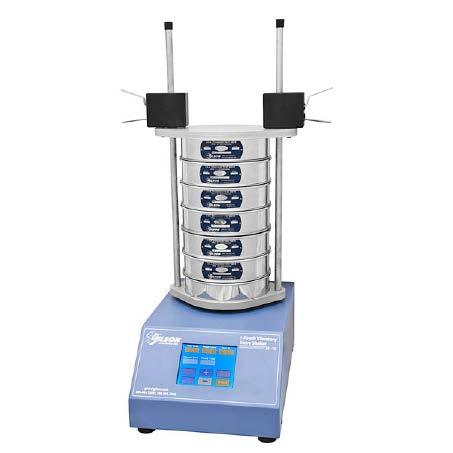
1 1-Touch Vibratory Sieve Shaker SS-10

2 Safety Instructions WARNING!! This machine operates on electric current. Improper operation could result in electrical shock, electrocution, or an explosion! 1. ALWAYS make sure the motor and other electrical components are appropriate and properly configured for your intended use and available power source. - The 1-Touch Vibratory Sieve Shaker is configured to operate on 115V/60Hz power supplies. 2. ALWAYS check electrical wiring for loose connections and for pinched or frayed wiring. 3. ALWAYS use properly-wired, three-pronged plus, or otherwise ground the machine. 4. ALWAYS disconnect and lock out power supply before performing maintenance and repairs. WARNING! DO NOT operate the machine without having all covers and case in place. ALWAYS unplug or disconnect machine from the power source when the units not in operation. 1-Touch Vibratory Sieve Shaker Introduction The 1-Touch Vibratory Sieve Shaker for 8in and 200mm sieves combines the particle sizing technology that is fast, and provides accurate separations. The three-dimensional sieving action evenly distributes and continuously reorients particles across the mesh surface to insure optimum sieving performance. Power level, sieving time and interval pauses are all controlled and programmed on the Touch Screen. Unpacking & Set-Up: 1. The SS-10 weighs approximately 90lb, make sure to use appropriate equipment to uncrate the sieve shaker. -Wear safety glasses and work gloves. 2. Before opening examine the shipping carton for signs of damage. -If there is damage report to the shipper immediately. Leave the carton as intact as possible to facilitate return shipping. NOTE: Numbers in parentheses refer to the SS-10 Parts Diagram. 3. Lift the Base Assembly Item (1) from the carton, position it on a solid, level work surface. Then examine the unit again for any possible damage that may have been concealed. 4. The Plastic Clearance Spacer (2) is secured for shipping to the top of the SS-10 Base Assembly with three 1/4-20x 1.75 stainless steel flat-head screws (4). Using the Allen Key wrench, remove the three screws and set aside. Leave the spacer on top of the base assembly. 5. The Sieve Stack Assembly includes partially assembled: -Two Clamp Rods (5) -Bottom and top Covers (3 and 6) - Clamps (9) -Top and base Gaskets (12 and 13) 6. To complete assembly, rotate the Clamps so that the tabs are facing outward. Slide the Top Cover Plate up and secure it to the clamps by installing the x 1 Shoulder Bolts (10) through the bottom of the plate into the threaded holes in the bottom of each clamp. Tighten securely. 7. Place the Sieve Stack Assembly on top of the plastic Clearance Space. Aligning the three holes in the spacer and base plate with the threaded holes in the top of the base assembly. Install the three stainless steel flat-head screws, and tighten securely. 8. Install the adhesive-backed, peel and stick Base Gasket (13) into the recess in the Bottom Cover (3). 9. Move the assembled SS-10 into place on a solid and level work surface. Insert the female end of the included power cord into the power connection on the back of the SS-10. Power ON/OFF is controlled by the rocker switch adjacent to this connection. 8in Round Test Sieves


3 Clamping System: SS-10 Parts Diagram Gilson sieve clamps are designed for efficiency, ease of use, and rugged dependability. They allow fast, easy insertion and removal of sieve stacks, while keeping sieves tightly secured in place during testing. Note: DO NOT lubricate the guide rods or internal contact surfaces of the clamps. If slippage occurs during operation, clean and degrease, then lightly sand the guide rods. Each clamp has two levers; the top one is light gray and the bottom is red. To reposition the stack cover on the guide rods, maintain slight upward pressure on both the red levers at once while sliding the clamps up or down. Moving the stack cover, keep the clamps at an even height to prevent binding. When the cover is at the desired position, release pressure on the levers and the cover will stay in place. As soon as the stack cover is seated over the top of the sieve stack, press downward on the gray levers several times until the pressure is applied to clamp the stack tightly. To release the stack, lift up both the red levers simultaneously. Slide the cover up slightly to clear the top of the sieve stack. When the cover is out of the way, release the pressure on the red levers. SS-10 Parts List Item No. Parts No. No. Req d Description 1 WGV8-BASE_ASSY 1 Base Assembly 2 WGV8-SPACER 1 Clearance Spacer 3 WGV8-BOTTOM_COVER_ASSY 1 Bottom Cover Assembly 4 WGSW FAMSS 3 ¼-20 x 1.75 Flat Head Allen (Stainless) 5 WGV8-CLAMP_ROD 2 Clamp Rod 6 WGV8-TOP_COVER_ASSY 1 Top Cover Assembly 7 WGNT-513ACNOSS 2 ½-13 Acorn Nut (Stainless) 8 WGNT-513HJNOSS 2 ½-13 Hex Jam Nut (Stainless) 9R WGSC-CLAMP_RIGHT 1 Sieve Clamp, Right-Hand Side 9L WGSC-CLAMP_LEFT 1 Sieve Clamp, Left-Hand Side 10 WGSW-SB CSNSS 2 Shoulder Bolt 1-32 x 1 in 11 WGAS-PP-SK Power Cord 12 WGV8-TOP_PLATE_GASKET 1 Top Base Plate Gasket 13 WGV8-PLATE_GASKET 1 Base Plate Gasket 14 WGUS-1-1/2 FOOT 4 1-1/2 Rubber Foot


4 NOTE: The Touch Screen display is not moisture resistant. Avoid the use of liquids in its vicinity and use caution when cleaning the display. Moisture damage to the Touch Screen is not covered by warranty. Test Time Test Time is the amount of time the sample will be actively vibrated. The count-down timer is adjustable from 00:00 to 99:59 minutes: seconds. When the timer reaches zero, the unit will stop vibrating and beep. Editing the Test Time Display To adjust, press the Test Time display once. The outline and numbers inside turn yellow and the first digit will flash. The flashing digit can be adjusted using the +/- buttons. Press the Test Time display again once the desired value has been adjusted. The next digit will begin to flash and is now adjustable with the +/- buttons. Continue this process until all Test Time digits are set. Press the Test Time display box once while the last digits is flashing to accept the changes and return to the screen to idle. Touch Screen Operation: Inputting data on the Touch Screen is simply pressing the designated area with your finger. - A gentle pressure usually works better than a hard push with the finger. Using other objects on the screen is not recommended as it could damage the screen. The Touch Screen is used both to input and display information of the SS-10 Shaker. The five upper displays are: 1. Test Time 2. Power Level 3. Interval Time 4. Pause Time 5. Test ID The six lower sections function as control buttons to start or stop a test cycle, enable or disable vibration intervals, lock the screen and to select a test ID. The + and - buttons are set to input values for the fields. NOTE: Pressing the Touch Screen anywhere other than the Test Time box, or the +/- buttons at any time during the editing will quickly accept any changes made and return the screen to idle.


5 Interval & Pause Time The Interval feature allows timed pauses to be introduced into cycles of active vibration. Separation of some materials is improved by the interruptions in the vibrations cycle that promote particle reorientation. Interval Time: The period of active vibration between pause. Pause Time: Time that the unit is not vibrating. Test Time: Uses both the Interval Time and the Pause Time. Enable/Disable Interval: The Interval feature is toggled on and off using this button. Enable Interval: When Interval Time and Pause Time are solid grey. Disable Interval: When the Interval Time and Pause Time boxes display settable digits. With the Interval feature enabled, times must be entered in the Interval Time and Pause Time. Times can be any value up to the period selected for Total Time. Pause times are typically only a few seconds. Editing the Interval Time & Pause Time Displays Enable the Interval button, press the display box of the Interval Time or Pause Time box once. The outline and numbers inside turn yellow and the first digit will flash. The flashing digit is adjustable by pressing the +/- buttons. Press the display button again once the desired value has been set. Continue this until you have all the digits set. Press the display box once while the last digit is flashing accepts the changes and returns to the screen to idle. NOTE: Pressing the Touch Screen anywhere other than the edited display box or the +/- buttons at any time during editing will quickly accept any changes made and return to the screen to idle. Power Level: Power Level is the amount of vibration produced by the unit. Vibration intensity on a relative scale can be selected between d1 (low) and 10 (high). Actual vibration amplitude and acceleration forces on the specimen particles will vary and are influenced by the bulk density and total mass of the sample, as well as the height of the sieve stack. Editing Power Level Settings: Press the Power Level box once. Units of measure and title of the box will turn yellow and begin to flash. The +/- buttons will adjust the value. The selectable values range from 1 to 10 on a relative scale. When the value is displayed, press the display again to accept. Test ID: The Test ID display and the Save/Delete Test ID toggle button are used to save and retrieve display settings. The Test ID display shows the current selected location from If nothing has been saved in that location, zeros will show and the blue Save Test ID button is shown. If values are already stored at this location, they will be displayed with the red Delete Test ID button. Pressing Delete will remove stored information. The display does not change until new data is entered. To create a new ID, either start at a location that has no data stored or delete stored values to clear the memory space. Press the Test ID display box, wait for the first digit to turn yellow and flash. Set the value using the +/- buttons and press the display again. Repeat the process to set the second digit and press to save the test ID location. Proceed to the other locations and set the values as described above. Press the blue Save Test ID button to save all information at that location once complete. Lock/Unlock Screen Button: The Lock/Unlock Screen button protects against unintentional changes. To activate, press the blue Lock Screen button. The button will change to display Unlock Screen. When the screen is locked only the Start/Stop and Unlock buttons function.

6 Start/Stop & Pause/Resume Buttons The Start/Stop button controls the test cycle. Pressing the green Start button activates vibration and the count-down timer to the selected values. Pressing the red Stop button stops the machine immediately and resets the timer. Once started, the Save/Delete Test ID button is converted into a Pause/Resume button. Pressing Pause temporarily halts the test cycle and timer. Resume button will continue the test at the time remaining. The SS-10 accepts up to eight full-height or sixteen half-height round test sieves of 8in or 200mm. NOTE: 8in and 200mm sieves CANNOT be used in the same stack. The SS-10 can test a wide variety of materials, combinations of power levels, test times and interval times must be determined experimentally. Low initial power and time settings are recommended when testing an unfamiliar material. Settings may be increased when gradually until complete separation is achieved. Inserting the optional GAA-19 Clear Acrylic 8in Sieve Space in a sieve stack allows visual observation of specimen action to determine optimum settings for a given material. When additional one minute increments of operation at higher power levels produce less than 1% of total weight difference in material passing a given sieve complete separation can be assumed. In addition to material type, power input and time, differences in sieve stack height and specimen weights may also cause performance variations. Gilson Test Sieves: ASTM and ISO Test Sieves are categorized in three different classes: 1. Compliance Test Sieves are supplied with a basic certificate of manufacturing conformance. 2. Inspection Test Sieves have a specified number of openings measured and reported for each sieve. 3. Calibration Test Sieves have two to three times as many openings measured on each sieve, and are supplied with more detailed documentation. Mesh Opening: Opening sizes are listed using standard millimeter (mm) or micrometer (um) descriptions, as well as traditional inch and number designations where appropriate. - Gilson offers all mesh sizes, but not all sizes are available in every frame diameter. - ISO Sieve Cloth can be mounted in 8in (203mm) frames when special-ordered. These items are nonreturnable when supplied as ordered. Frame Diameter: Frames should accommodate the entire sample volume with enough surface area to avoid overloading individual sieves. The diameter selected must also fit the sieve shaker being used. Frame Height: Sieve frames are designated as Full-Height or Half-Height. Intermediate-Height sieves are also available for 3in and 12in diameter. - Half or Intermediate-Height frames allow a greater number of sieves to be used when stack height is limited. - Full-Height frames allow free movement of larger particles during agitation for more efficient separation.
In-Ceiling Electric Motorized Front Projection Screen Evanesce Series. User s Guide
 In-Ceiling Electric Motorized Front Projection Screen Evanesce Series User s Guide Important Safety & Warning Precautions Make sure to read this user s guide and follow the procedures below. Caution: The
Vibratory Deck Sieves 15 in. (380 mm)
") Instruction Sheet P/N 1604433-01 Vibratory Deck Sieves 15 in. (380 mm) Introduction This instruction sheet covers the vibratory deck sieves listed in the following tables. 15-Inch Deck Sieves with 2.5
Instruction Sheet P/N 1604433-01 Vibratory Deck Sieves 15 in. (380 mm) Introduction This instruction sheet covers the vibratory deck sieves listed in the following tables. 15-Inch Deck Sieves with 2.5
READ ME FIRST. Touchstone TV Lift
 Whisper Lift II PRO 2 READ ME FIRST 1. After completing the unpacking and uncrating of the cabinet, you will find the Owner s Manual, TV, installation hardware, and the wireless remote all together and
Caution. Hanging the Screen:
 Installation Instructions for Laminar and Laminar XL Projection Screens Caution 1. Read Instructions through completely before proceeding; keep them for future reference. Follow these instructions carefully.
Instruction manual. KUZMA 4POINT 14 inch TONEARM Serial Number:
 Instruction manual KUZMA 4POINT 14 inch TONEARM Serial Number:.. 2016-09 1 KUZMA LTD INSTRUCTION MANUAL FOR 4POINT 14 tonearm The 4POINT 14 tonearm is a very precisely engineered piece of equipment, however,
Instruction Manual Fixed Speed Vortex Mixer Analog Vortex Mixer Digital Vortex Mixer Pulsing Vortex Mixer
 Instruction Manual Fixed Speed Vortex Mixer Analog Vortex Mixer Digital Vortex Mixer Pulsing Vortex Mixer Table of Contents Package Contents............ 1 Warranty............ 1 Installation............
High Performance DL-60 (Gold Plus) (7 in - 13 in) Dual Lane Spliceable Tape Feeder Part Number: Revision 3 Sep No.
 (7 in - 13 in) Dual Lane Spliceable Tape Feeder Part Number: Revision 3 Sep No.") 8mm High Performance DL-60 (Gold Plus) (7 in - 13 in) Dual Lane Spliceable Tape Feeder Part Number: 50381212 Revision 3 Sep. 2010 No. 0730D-E043 Page i Table of Contents Functional Description...1 Procedures
8mm High Performance DL-60 (Gold Plus) (7 in - 13 in) Dual Lane Spliceable Tape Feeder Part Number: 50381212 Revision 3 Sep. 2010 No. 0730D-E043 Page i Table of Contents Functional Description...1 Procedures
Electric Motorized Projection Screen PowerMax Tension Series
 Electric Motorized Projection Screen PowerMax Tension Series User s Guide Important Safety & Warning Precautions Make sure to read this user s guide and follow the procedures below. Caution: The screen
Electric Wall/Ceiling Projection Screen Saker Tab-Tension Series User s Guide
 Electric Wall/Ceiling Projection Screen Saker Tab-Tension Series User s Guide Important Safety & Warning Precautions Make sure to read this user s guide and follow the procedures below. Caution: The screen
Intelligent Pendulum Hardness Tester BEVS 1306 User Manual
 Intelligent Pendulum Hardness Tester BEVS 1306 User Manual Please read the user manual before operation. PAGE 1 Content 1. Company Profile... 3 2. Product Introduction... 3 3. Operation Instruction...
TV Lift System Model CL-65 Installation Instructions
 TV Lift System Model CL-65 Installation Instructions Contact: Support@Nexus21.com Toll Free: (866) 500-5438 Phone: (480) 951-6885 Fax: (480) 951-6879 Revised: 01/17/17 Below is a parts list describing
Tube Roller Shakers. User Guide. Version 1.2
 Tube Roller Shakers User Guide Version 1.2 Control panel Rollers Side retaining panels Analog models LED display Drip tray (not visible) Digital models Power On/Off and control dial Roller retaining panel
OPERATION AND MAINTENANCE MANUAL
 OPERATION AND MAINTENANCE MANUAL SERIAL NUMBER CUSTOMER: SALES REP.: CONTENTS Mixer Installation / Assembly / Dimension Drawings Safety... 1 Customer Service Contact... 1 Initial Inspection... 2 Installation...2
Basic Vortex Mixer Standard Vortex Mixer Advanced Vortex Mixer Pulsing Vortex Mixer
 Instruction Manual Manual Basic Vortex Mixer Standard Vortex Mixer Advanced Vortex Mixer Pulsing Vortex Mixer Table of Contents Package Contents............... 1 Warranty............... 1 Installation...............
Check what you have received against the component checklist and hardware above.
 SA46S SA46W SA46B SA46PB Component Checklist Installation Instructions SYSTEMA Systema Monitor Arm 460mm HARDWARE Display Mounting Spacers (x4) Display Mounting Screws Arm Assembly VESA monitor head M4
Electric Wall/Ceiling Projection Screen Saker Series User s Guide
 Electric Wall/Ceiling Projection Screen Saker Series User s Guide Important Safety & Warning Precautions Make sure to read this user s guide and follow the procedures below. Caution: The screen s Black
Orbit TM DIGITAL SHAKERS
 Orbit TM DIGITAL SHAKERS INSTRUCTION MANUAL Models P2, P4, M60, 300, 1000, 1900 Labnet International PO Box 841 Woodbridge, NJ 07095 Phone: 732 417-0700 Fax: 732 417-1750 email: labnet@labnetlink.com 2
2.4 METER SERIES 1250 ANTENNA SYSTEM
 June 1,2009 Revision B Assembly Manual 2.4 METER SERIES 1250 ANTENNA SYSTEM General Dynamics SATCOM Technologies 1500 Prodelin Drive Newton NC 28658 2.4 Meter 2 Piece Az/El Installation Instructions B
EN - English Washington Street Melrose, MA Phone Toll Free Revision 4 20/06/17
 - English... 1 Instruction Manual Vortex Mixer, Mini Fix Speed, VXMNFS Vortex Mixer, Mini Analog, VXMNAL Vortex Mixer, Mini Digital, VXMNDG Vortex Mixer, Mini Pulsing, VXMNPS 99 Washington Street Melrose,
INSTRUCTION AND MAINTENANCE VIDEO MOTORE PROJECTION SCREEN
 INSTRUCTION AND MAINTENANCE VIDEO MOTORE PROJECTION SCREEN 1.1 TECHNICAL DATA PRODUCT DESCRIPTION Screens made with the following projection fabrics: SOFT WHITE, MATT WHITE SOFT, SOFT WHITE TRANSOUND,
SCREEN WINCH SYSTEM INSTALLATION MANUAL FOR SCREENS UP TO 300 cm. of width
 SCREEN WINCH SYSTEM INSTALLATION MANUAL FOR SCREENS UP TO 300 cm. of width Before installing the screen winch system, please read the following instructions carefully: The screen winch system must be used
Turret Replacement Instruction Manual
 Automatic Multi-Satellite TV Antenna Turret Replacement Instruction Manual for models RPSKLGL, RPSKSML, SK-LG00, SK-SM00, & RP-SWM For help, email help@winegard.com or call -800-788-7 568 Raising the Antenna
1.8 METER SERIES 1183 Az/El MOUNT ANTENNA SYSTEM
 REVISION G January 11, 2002 ASSEMBLY MANUAL 1.8 METER SERIES 1183 Az/El MOUNT ANTENNA SYSTEM PRODELIN CORPORATION 1500 Prodelin Drive Newton NC 28658 1.8 METER SERIES 1183 Az/El MOUNT ANTENNA SYSTEM G
Solid-State Digital Timer
 Solid-State Digital Timer 1/16 DIN, Digital-Set Timer with 0.1 Second to 9,990 Hours Range 8 field-selectable operation modes Universal AC/DC supply voltage timers available Operations include ON-delay,
Technical Information Bulletin
 June 4, 2001 #TIB0003 Units Affected: Model Serial Numbers Model Serial Numbers SVT-2PRO T2PDxxxxxxxxx SVTAV AXVDxxxxxxxxx ATLDxxxxxxxxx BJIDMAxxxxxxx SVT-2PROJ T2PJxxxxxxxxx SVTAVJ BAHJxxxxxxxxx ATLJxxxxxxxxx
SCREEN WINCH SYSTEM INSTALLATION MANUAL FOR SCREENS UP TO 300 cm. of width
 SCREEN WINCH SYSTEM INSTALLATION MANUAL FOR SCREENS UP TO 300 cm. of width Before installing the screen winch system, please read the following instructions carefully: The screen winch system must be used
Setup Guide. Read me BefoRe unpacking!
 Setup Guide Read me BefoRe unpacking! Package Contents In The Replicator package The Replicator SD card (in The Replicator SD card slot) In the Accessory Box found within The Replicator frame Single or
MY-HITE ADJUSTABLE TABLE
 MY-HITE ADJUSTABLE TABLE Corner T Leg Base Model Number : FCNAHBT Please Read Instructions Before Use ASSEMBLY INSTRUCTIONS ALL WORKSTYLES WELCOME Thank you for choosing Friant. We appreciate the trust
Endecotts Limited, Lombard Road, London SW19 3TZ England Tel: + 44 (0) Fax: + 44 (0)
 Fax: + 44 (0)") Endecotts Limited, Lombard Road, London SW19 3TZ England Tel: + 44 (0) 20 8542 8121 Fax: + 44 (0) 20 8543 6629 E-mail: sales@endecotts.com web site http://www.endecotts.com The Octagon Digital User Guide
Endecotts Limited, Lombard Road, London SW19 3TZ England Tel: + 44 (0) 20 8542 8121 Fax: + 44 (0) 20 8543 6629 E-mail: sales@endecotts.com web site http://www.endecotts.com The Octagon Digital User Guide
8mm PrecisionPro (Green) DL Spliceable 7-13 Tape Feeder. T Rev. B hd This document supports assembly Rev. -
 DL Spliceable 7-13 Tape Feeder. T Rev. B hd This document supports assembly Rev. -") 8mm PrecisionPro (Green) DL Spliceable Tape Feeder 8mm PrecisionPro (Green) DL Spliceable Tape Feeder 8mm PrecisionPro (Green) DL Spliceable Tape Feeder 8mm PrecisionPro (Green) DL Spliceable 7-13 Tape
8mm PrecisionPro (Green) DL Spliceable Tape Feeder 8mm PrecisionPro (Green) DL Spliceable Tape Feeder 8mm PrecisionPro (Green) DL Spliceable Tape Feeder 8mm PrecisionPro (Green) DL Spliceable 7-13 Tape
Motor Operated Solar Shade with Valance Installation and Care Instructions Complete Video Instructions Available Online at
 * Motor Operated Solar Shade with Valance Installation and Care Instructions Complete Video Instructions Available Online at www.keystonefabrics.com Step 1: Identify the parts of your shade (parts shown
2178 Fiber Optic Splice Case and 2181 Cable Addition Kit
 2178 Fiber Optic Splice Case and 2181 Cable Addition Kit Instructions January 1994 Issue 1, 34-7029-6387-6 1 2 Contents: 1.0 General... 4 2.0 Specifications... 4 3.0 Kit Contents... 5 SECTION 1: 2178 Splice
Index. Index. 1.0 Introduction...2 This Manual Operation Finger Lift Cable Lift Pneumatic Operation...
 Li nearenc oder s wi t httlout put Us ermanual Index 1.0 Introduction..........................2 This Manual...........................2 2.0 Safety Summary......................3 Terms in this Manual....................3
3M Distribution Box (DDB)
") 3M Distribution Box (DDB) Merged Copper and Fiber Pole/Post Mount Enclosure Installation Instructions November 2015 78-0015-2736-1-A 2 November 2015 78-0015-2736-1-A Contents 1.0 General 2.0 Enclosure
3M Distribution Box (DDB) Merged Copper and Fiber Pole/Post Mount Enclosure Installation Instructions November 2015 78-0015-2736-1-A 2 November 2015 78-0015-2736-1-A Contents 1.0 General 2.0 Enclosure
Starling Tab-Tension 2 Series
 Electric Wall/Ceiling Projection Screen Starling Tab-Tension 2 Series For: Spectra White FG and CineGrey 5D User s Guide Important Safety & Warning Precautions Make sure to read this user s guide and follow
K Service Source. Apple High-Res Monochrome Monitor
 K Service Source Apple High-Res Monochrome Monitor K Service Source Specifications Apple High-Resolution Monochrome Monitor Specifications Characteristics - 1 Characteristics Picture Tube 12-in. diagonal
A449-6S 70 CENTIMETER FM YAGI ANTENNA MHz
 ASSEMBLY AND INSTALLATION A449-6S 70 CENTIMETER FM YAGI ANTENNA 440-450 MHz COMMUNICATIONS ANTENNAS 951425 (7/93) WARNING THIS ANTENNA IS AN ELECTRICAL CONDUCTOR. CONTACT WITH POWER LINES CAN RESULT IN
PLL1920M LED LCD Monitor
 PLL1920M LED LCD Monitor USER'S GUIDE www.planar.com Content Operation Instructions...1 Safety Precautions...2 First Setup...3 Front View of the Product...4 Rear View of the Product...5 Installation...6
Installation Guide OvalSox TM Cable
 Installation Guide OvalSox TM Cable Thank you for selecting a DuctSox System. This guide will be helpful for the installation of an OvalSox Cable System. Sections of fabric will be labeled, assembled,
Cellular Signal Booster
 Drive 4G-X Cellular Signal Booster THE ALUMINUM CASING OF YOUR SIGNAL BOOSTER!! WILL ADJUST TO THE TEMPERATURE OF ITS ENVIRONMENT, BUT IS DESIGNED TO PROTECT THE SIGNAL BOOSTER TECHNOLOGY. FOR EXAMPLE,
A CENTIMETER FM YAGI ANTENNA MHz
 ASSEMBLY AND INSTALLATION A449-70 CENTIMETER FM YAGI ANTENNA 440-450 MHz COMMUNICATIONS ANTENNAS 951424 (10/91) WARNING THIS ANTENNA IS AN ELECTRICAL CONDUCTOR. CONTACT WITH POWER LINES CAN RESULT IN DEATH
High Performance (Gold Plus) Spliceable Tape Feeder Part Number: Part Number: Revision 3 Jun 2008 No.
 Spliceable Tape Feeder Part Number: Part Number: Revision 3 Jun 2008 No.") 8mm High Performance (Gold Plus) Spliceable Tape Feeder Part Number: 50934707 12mm High Performance (Gold Plus) Spliceable Tape Feeder Part Number: 50934807 Revision 3 Jun 2008 No. 0930D-E010 i Table
8mm High Performance (Gold Plus) Spliceable Tape Feeder Part Number: 50934707 12mm High Performance (Gold Plus) Spliceable Tape Feeder Part Number: 50934807 Revision 3 Jun 2008 No. 0930D-E010 i Table
INSTALLATION INSTRUCTIONS
 LIGHTGUARD 350-20-WTC SEALED FIBER OPTIC CLOSURE VIEW ONLINE TABLE OF CONTENTS: GENERAL...2 SPECIFICATIONS...2 PACKAGE CONTENTS...3 PACKAGE CONTENTS: ACCESSORIES...3 RECOMMENDED TOOLS...3 ADD-ON COMPONENTS...4
Guía del usuario Español ( 7 10 ) Guide d utilisation Français ( ) Guida per l uso Italiano ( ) Benutzerhandbuch Deutsch ( )
 Guide d utilisation Français ( ) Guida per l uso Italiano ( ) Benutzerhandbuch Deutsch ( )") User Guide English ( 3 6 ) Guía del usuario Español ( 7 10 ) Guide d utilisation Français ( 11 14 ) Guida per l uso Italiano ( 15 18 ) Benutzerhandbuch Deutsch ( 19 22 ) Appendix English ( 23 ) User Guide
User Guide English ( 3 6 ) Guía del usuario Español ( 7 10 ) Guide d utilisation Français ( 11 14 ) Guida per l uso Italiano ( 15 18 ) Benutzerhandbuch Deutsch ( 19 22 ) Appendix English ( 23 ) User Guide
Website: Tel: ADDRESS: 6475 Las Positas Rd. Livermore, CA Item No. E5B/E5S Installation Guide
 Website: www.flexispot.com Tel: -855-4-808 ADDRESS: 6475 Las Positas Rd. Livermore, CA 9455 Item No. E5B/E5S Installation Guide Specifications Step Column 3 Max. Weight Capacity 0 Ibs (00 kg) Speed 38mm/s
Troubleshooting Guide 9630 Series
 Troubleshooting Guide 9630 Series Satellite Solutions for Mobile Markets 11200 Hampshire Avenue South, Bloomington, MN 55438-2453 Phone: (800) 982-9920 Fax: (952) 922-8424 www.kingcontrols.com 1305-SEMI
DLP ANTENNA INSTRUCTION MANUAL. Dielectric LLC 22 Tower Road Raymond, Maine Phone:
 DLP ANTENNA INSTRUCTION MANUAL Dielectric LLC 22 Tower Road Raymond, Maine 04071 Phone: 800-341-9678 TABLE OF CONTENTS Section Title Page Warnings 1 Return Policy. 1 Factory Tests... 1 Antenna Description....
CN Remove the scanner assembly (X476 and X576 models) and all doors/covers.
 and all doors/covers.") CN598-67045 www.hp.com/support IMPORTANT: Ensure the product firmware is upgraded to at least version 1336MR before performing this repair procedure. If the firmware upgrade cannot be completed, contact
CN598-67045 www.hp.com/support IMPORTANT: Ensure the product firmware is upgraded to at least version 1336MR before performing this repair procedure. If the firmware upgrade cannot be completed, contact
choice of types to suit many applications, from simple containers, toolboxes, industrial canister type vacuum cleaner, insulation
 Solutions Inc. TL-7800 Line The DFCI TL-7800 Line of Toggle Latches offers the designer a wide choice of types to suit many applications, from simple containers, toolboxes, industrial canister type vacuum
Electric Wall/Ceiling Projection Screen Saker Plus Series User s Guide
 Electric Wall/Ceiling Projection Screen Saker Plus Series User s Guide Important Safety & Warning Precautions Make sure to read this user s guide and follow the procedures below. Caution: The screen s
MODELS USIX-024 AND USIX-120 INSTRUCTION SHEET FOR FEDERAL SIGNAL UNISTAT STATUS INDICATOR MODEL USIX
 2562089B REV. B 110 Printed in U.S.A. MODELS USIX-024 AND USIX-120 INSTRUCTION SHEET FOR FEDERAL SIGNAL UNISTAT STATUS INDICATOR MODEL USIX Address all communications and shipments to: FEDERAL SIGNAL CORPORATION
Fully ly Automaticti. Motorised Satellite t TV System. User s manual REV
 REV. 1.0 Fully ly Automaticti Motorised Satellite t TV System User s manual Customer Help Line: 1300 139 255 Support Email: support@satkingpromax.com.au Website: www.satkingpromax.com.au www.satkingpromax.com.au
Service manual Cantano W/T
 Service manual Cantano W/T Here you will see everything that should be included in your Cantano package 2 Prerequisite: Placement and leveling of the drive 5 Setting up the motor and connecting it to the
ASSEMBLY, INSTALLATION, AND REMOVAL OF CONTACTS AND MODULES
 ASSEMBLY, INSTALLATION, AND REMOVAL OF CONTACTS AND MODULES FOR 75 OHM AND 75 OHM HD COAXIAL CONTACTS AND MODULES Table of Contents SECTION 1 RECEIVER CONTACT ASSEMBLY INSTRUCTIONS SECTION 2 ITA CONTACT
3. Electronics and MMU2 unit assembly
 Written By: Jakub Dolezal 2018 manual.prusa3d.com/ Page 1 of 34 Step 1 Tools necessary for this chapter Please prepare tools for this chapter: 2.5mm Allen key for M3 screws 2mm Allen key for nut alignment
Troubleshooting Guide for E-Poll Book
 Troubleshooting Guide for E-Poll Book CHANGING USERS ON THE E-POLL BOOK Changing Users on the E-poll Book 1. Tap Return to Main button on the voter search screen. 2. Tap on the Manage Polls tab in the
Desk Mount Articulating Dual Monitor Arm with Cable Management & Height Adjust
 Desk Mount Articulating Dual Monitor Arm with Cable Management & Height Adjust ARMDUAL *actual product may vary from photos DE: Bedienungsanleitung - de.startech.com FR: Guide de l'utilisateur - fr.startech.com
VPM2. Operator's Manual
 VPM2 Operator's Manual Whip Mix Corporation 361 Farmington Ave. P.O. Box 17183 Louisville, KY 40217-0183 USA 502-637-1451 800-626-5651 Fax 502-634-4512 www.whipmix.com Features The Whip Mix VPM2 is designed
WINEGARD INSTALLATION MANUAL. Model GM Carryout Ladder Mount for mounting pipes with outer diameters between 1 to 1-1/8
 WINEGARD INSTALLATION MANUAL Model GM-3000 Carryout Ladder Mount for mounting pipes with outer diameters between 1 to 1-1/8 WARNING: DO NOT USE THE LADDER MOUNT AS A STEP! NOT INTENDED FOR USE WITH THE
Assembling and Mounting the Presentation Display, Speakers, Speaker Screens, and Table Door
 CHAPTER 8 Assembling and Mounting the Presentation Display, Speakers, Speaker Screens, and Table Door July 13, 2012, This document provides you with the procedures you perform to assemble and mount the
Electric Motorized Projection Screen Spectrum Tab-Tension Series User s Guide
 Electric Motorized Projection Screen Spectrum Tab-Tension Series User s Guide Important Safety Precautions Make sure to read this user s guide and follow the procedures below prior to screen operation.
PC-250. SMD Taped Parts Counter Operator s Manual. ISO 9001:2008 Certified. V-TEK, Incorporated 751 Summit Avenue Mankato, MN USA
 PC-250 SMD Taped Parts Counter Operator s Manual ISO 9001:2008 Certified V-TEK, Incorporated 751 Summit Avenue Mankato, MN 56001 USA (P) 507-387-2039 (F) 507-387-2257 www.vtekusa.com Dear Customer: All
3M Fiber Optic Splice Closure 2178-XSB/XSB-FR & 2178-XLB/XLB-FR 3M Cable Addition Kit 2181-XB/XB-FR
 3M Fiber Optic Splice Closure 2178-XSB/XSB-FR & 2178-XLB/XLB-FR 3M Cable Addition Kit 2181-XB/XB-FR Instructions July 2010 78-8135-0094-5-K 3 1.0 General 1.1 3M Fiber Optic Splice Closure 2178-XSB The
3M Fiber Optic Splice Closure 2178-XL & 2178-XL/FR 3M Cable Addition Kit 2181-XL and 2181-XL/FR
 3M Fiber Optic Splice Closure 2178-XL & 2178-XL/FR 3M Cable Addition Kit 2181-XL and 2181-XL/FR Instructions July 2010 3 1.0 Contents 1.0 General...3 2.0 Kit Contents...3 3.0 Cable Preparation...4 4.0
K Service Source. Apple High-Res Monochrome Monitor
 K Service Source Apple High-Res Monochrome Monitor K Service Source Specifications Apple High-Resolution Monochrome Monitor Specifications Characteristics - 1 Characteristics Picture Tube 12-in. diagonal
OPERATION MANUAL UCHIDA YOKO CO., LTD., TOKYO, JAPAN. Jul 23, 2012 USA
 OPERATION MANUAL UCHIDA YOKO CO., LTD., TOKYO, JAPAN Jul 23, 2012 USA Use machine only after reading the "Safety Instructions" given below carefully. These safety instructions are given to ensure that
Proper Installation of SCR s will Extend Life Author - George A. Sites, AMETEK HDR Power Systems
 INTRODUCTION Application Note 1019 Proper Installation of SCR s will Extend Life Author - George A. Sites, AMETEK HDR Power Systems The review of How to install an SCR and the understanding of Why proper
Tension Electric Screen. CineTension Series. Users Guide USER S GUIDE. Rev. 1.1
 Tension Electric Screen CineTension Series Users Guide USER S GUIDE IMPORTANT SAFETY INSTRUCTIONS Please read this guide prior to installation. Make sure the current rating is equal to the appliance rating
User Manual. Adjustable Speed Vortex. Fixed Speed Vortex
 User Manual MX-S MX-F Adjustable Speed Vortex Fixed Speed Vortex Please read the User Manual carefully before use, and follow all operating and safety instructions! Technical specifications and outline
Cable System Installation Guide
 Overview Cable System Installation Guide 5/19/2008 Our recommended approach for the installation of your Circle Graphics Cable Systems on the panels in your market is to install the fixed hardware (namely
VPM2. Operation Manual
 VPM2 Operation Manual Whip Corporation 361 Farmington Ave. P.O. Box 17183 Louisville, KY 40217-0183 USA 502-637-1451 800-626-5651 Fax 502-634-4512 www.whipmix.com LISTED Features The Whip VPM2 is designed
2178-L/S Series Fiber Optic Splice Case with Gasket
 2178-L/S Series Fiber Optic Splice Case with Gasket Instructions for: 2178-S Splice Case 2178-LS Splice Case 2178-LL Splice Case 2181-LS Cable Addition Kit May 1997 34-7041-9949-5-A 1 Table of Contents
Tube Rotator. User Guide. Version 1.2
 Tube Rotator User Guide Version 1.2 Figure 1: Fixed Speed Model Tube holder spindle Tilt adjustment wheel IEC power inlet socket (at rear) Power on/off switch Figure 2: Variable Speed Model Tube holder
Important Safety & Warning Precautions
 Electric Motorized Projection Screen VMAX 2 Series User s Guide Important Safety & Warning Precautions Make sure to read this user s guide and follow the procedure below. Caution: The screen s Black Top
KUZMA 4POINT TONEARM
 KUZMA 4POINT TONEARM Instruction manual 2008-6 Serial Number:.. 1 KUZMA LTD INSTRUCTION MANUAL FOR 4POINT tonearm The 4POINT tonearm is a very precisely engineered piece of equipment, however, the construction
SCREEN WINCH SYSTEM INSTALLATION MANUAL FOR SCREENS FROM 300 cm. UP TO 450 cm. of width
 SCREEN WINCH SYSTEM INSTALLATION MANUAL FOR SCREENS FROM 300 cm. UP TO 450 cm. of width Before installing the screen winch system, please read the following instructions carefully: The screen winch system
Backlight Replacement
 Installation Instructions Backlight Replacement Catalog Numbers 2711P-RL7C, 2711P-RL7C2, 2711P-RL10C, 2711P-RL10C2, 2711P-RL12C, 2711P-RL12C2, 2711P-RL15C Topic Page About This Publication 1 Important
Operation and Maintenance Guide Electric Needle Scalers
 Operation and Maintenance Guide Electric Needle Scalers Models Covered Model Number ENS100V ENS200V Electric Needle Scaler, 110V-1ph Electric Needle Scaler, 220V-1ph Description IMPA Number 59 12 01 59
COLORtube EQ Controller
 COLORtube EQ LED-EQ COLORtube EQ Controller LED-EQC USER MANUAL 32-band audio spectrum visualizer using LED tubes CHAUVET, 3000 N 29 th Ct, Hollywood, FL 33020 U.S.A (800) 762-1084 (954) 929-1115 FAX (954)
RT AUDIO RETRACTABLE CABLE
 AUDIO RETRACTABLE CABLE Welcome! Thank you for purchasing the MINI-ME RT300-134 audio Cable Retractor. We know you will find it easy to install, easy to use and easy to maintain. Our goal is to provide
USER S MANUAL. Save this manual for future reference. For a digital version of this manual, visit
 TM USER S MANUAL Save this manual for future reference. For a digital version of this manual, visit www.mylifter.com/installation. 4 5 TABLE OF CONTENTS 4 INSTALLING THE PULLEY SYSTEM FOR LIFTING 100
Model DT-311J. And DT-311J-230V(AC) DIGITAL STROBOSCOPE INSTRUCTION MANUAL
 DIGITAL STROBOSCOPE INSTRUCTION MANUAL") Test Equipment Depot - 800.517.8431-99 Washington Street Melrose, MA 02176 - TestEquipmentDepot.com Model DT-311J And DT-311J-230V(AC) DIGITAL STROBOSCOPE INSTRUCTION MANUAL 1. GENERAL The DT-311J DIGITAL
Test Equipment Depot - 800.517.8431-99 Washington Street Melrose, MA 02176 - TestEquipmentDepot.com Model DT-311J And DT-311J-230V(AC) DIGITAL STROBOSCOPE INSTRUCTION MANUAL 1. GENERAL The DT-311J DIGITAL
WaterVue TV Installation & User Manual
 WaterVue TV Installation & User Manual 19 Waterproof TV Dimensions of TV Front screen 486mm x 340mm x 3mm Mounting Plate 467mm x 324mm x 48mm 24 Waterproof TV Dimensions of TV Front screen 576mm x 395mm
LeRIBSS MTC MANUAL. Issue #1. March, MTC Control Unit Definitions, Information and Specifications. MTC Control Unit Electronic Schematics
 LeRIBSS MTC MANUAL Issue #1 March, 2008 Contents: MTC Control Unit MTC Control Unit Definitions, Information and Specifications Programming the MTC Control Unit Program Parameters Initial Setup Measuring
INSTALLATION INSTRUCTIONS
 INSTALLATION INSTRUCTIONS PARTS REQUIRED Parts in the box Single monitor Dual monitor M2 M8 M/Flex + (package contents will depend on configuration ordered) Tools required for installation 6.0 mm Hex Key
NewScope-7A Operating Manual
 2016 SIMMCONN Labs, LLC All rights reserved NewScope-7A Operating Manual Preliminary May 13, 2017 NewScope-7A Operating Manual 1 Introduction... 3 1.1 Kit compatibility... 3 2 Initial Inspection... 3 3
NWRG Nixie Watch. User Manual
 NWRG Nixie Watch User Manual 2 Copyright (C) 2012 Cathode Corner. All rights reserved. Printed in USA Watch made in USA 3 Table of Contents Introduction... 5 Warranty... 7 Operating Instructions... 9 Maintenance...
TracVision R6DX Installation Guide
 TracVision R6DX Installation Guide These instructions explain how to install the TracVision R6DX satellite TV antenna system on an RV or motor coach. Complete instructions on how to use the system are
3M Better Buried Closures
 3M Better Buried Closures Instructions March 2016 78-0015-2945-8-A Contents: 1.0 General... 3 2.0 Kit Contents... 3 3.0 Closure Selection Guide... 4 4.0 LHS End Cap Installation... 5 5.0 Cable Preparations...
AS-300D Series Smart Bench Scales Owner s Manual
 DETE CTO A Division of Cardinal Scale Manufacturing Co. AS-300D Series Smart Bench Scales Owner s Manual 8527-M214-O1 Rev B 01/03 PO BOX 151 WEBB CITY, MO 64870 417-673-4631 Printed in USA INTRODUCTION
Step 1. 2x Kep Nut 1x Left Motor Assembly
 Start with the build completed in Lesson 3 of the TETRIX Getting Started Guide. Steps 1 to 3 involve removing elements from the model. These elements will be reattached later. Parts to be Removed Step
PLL2210MW LED Monitor
 PLL2210MW LED Monitor USER'S GUIDE www.planar.com Content Operation Instructions...1 Safety Precautions...2 First Setup...3 Front View of the Product...4 Rear View of the Product...5 Quick Installation...6
3M Fiber Optic Splice Closure 2178-XL & 2178-XL/FR
 3M Fiber Optic Splice Closure 2178-XL & 2178-XL/FR 3M Cable Addition Kit 2181-XL and 2181-XL/FR Instructions September 2017 78-8130-5055-2-M 2 September 2017 78-8130-5055-2-M 1.0 Kit Contents 2.0 General...
SPIRAL MIXERS CONTENT CHAPTER 1 COMPANY BRIEF INTRODUCTION OPERATION INSTRUCTION
 SPIRAL MIXERS OPERATION INSTRUCTION CONTENT CHAPTER 1 COMPANY BRIEF INTRODUCTION.....P1 CHAPTER 2 PRODUCTION INTRODUCTION.....P2 2.1 Machine trait........p2-3 2.2 Technical parameter.......p4-6 CHAPTER
OPERATING MANUAL. Cole-Parmer Stir-Pak. Mixer Head Model Numbers , , , , & Mixer Controller Model Numbers
 OPERATING MANUAL Cole-Parmer Stir-Pak Mixer Head Model Numbers 50007-10, 50007-20, 50007-30, 50007-40, & Mixer Controller Model Numbers 50007-00 Cole-Parmer ServoDyne Mixer Head Model Numbers 50008-10,
ACCESSORIES MANUAL PART NUMBER: TNP500. Universal Tilt N Plug Interconnect Box USER'S GUIDE
 MANUAL PART NUMBER: 400-0091-003 TNP500 Universal Tilt N Plug Interconnect Box USER'S GUIDE INTRODUCTION Your purchase of the TNP100 Tilt N Plug Interconnect Box is greatly appreciated. We are sure you
Manual placement system MPL3100. for BGA, CSP and Fine-Pitch components
 Manual placement system MPL3100 for BGA, CSP and Fine-Pitch components Part No: MPL3100BA1.0e Issue Date: 02/2001 You have opted for an ESSEMTEC MPL3100 pick and place system. We thank you for this decision
PL2410W LCD Monitor USER'S GUIDE.
 PL2410W LCD Monitor USER'S GUIDE www.planar.com Content Operation Instructions...1 Safety Precautions...2 First Setup...3 Front View of the Product...4 Rear View of the Product...5 Quick Installation...6
SUBCARRIER TRANSFER FILTER INSTRUCTION BOOK IB622702
 SCF611S SUBCARRIER TRANSFER FILTER INSTRUCTION BOOK IB622702 SCF611S SUBCARRIER TRANSFER FILTER TABLE OF CONTENTS PAGE SHIPPING INSPECTION 2 MODULE CONFIGURATION 2 INSTALLING MODULES 2-3 CABLING 3 FRONT
TECHNICAL GUIDE. TOUGH GUN ThruArm G1 Series Robotic MIG Guns for FANUC Robots 100iC, 100iC-12, 100iC-6L, 100iC-7L, 120iC, 120iC-10L, 120iC-12L
 TECHNICAL GUIDE TOUGH GUN ThruArm G1 Series Robotic MIG Guns for FANUC Robots 100iC, 100iC-12, 100iC-6L, 100iC-7L, 120iC, 120iC-10L, 120iC-12L INSTALLATION MAINTENANCE TECHNICAL DATA OPTIONS EXPLODED VIEW