FireLite Operator s Manual
|
|
|
- Baldric Floyd
- 5 years ago
- Views:
Transcription


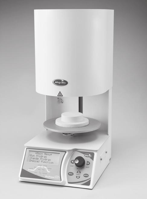
1 FireLite Operator s Manual Whip Mix Corporation 361 Farmington Ave. P.O. Box Louisville, KY USA Fax
2 Table of Contents Specifications...2 Accessories...3 Chapter One Getting Started Before Unpacking...3 Unpacking...3 Lifting and Carrying...3 Furnace Requirements...4 Installing the Vacuum Pump...5 Front Panel Controls and Indicators...6 Menu Selection Buttons...6 Changing Units of Measurement Between English and Metric...7 Night Mode...8 Idle Temperature Operation...8 Chapter Two Special Function Input Customize Program Finish Tune...9 Fast Cool with Vacuum...10 Adjusting Calibrations for Low-Fusing and High-Fusing Porcelains...10 Adjust High-Fusing Porcelain Calibration...10 Adjust Low-Fusing Porcelain Calibration...10 Displaying Muffle Hours...11 Displaying Software Version...11 Error Messages...11 Chapter Three Entering and Editing Programs To Enter and Edit a Program...12 Changing a Program While it is Running...12 Available Program Parameters...12 Chapter Four Running a Program To Start a Program...13 Skipping a Program Step...13 Chapter Five Maintenance Cleaning Your Furnace...13 Replacing the Muffle...13 If More Help is Needed...14 Replacement Parts Parts List...15 FireLite Accessory High Efficiency Vacuum Pump...14 Conversion Table Fahrenheit to Celsius...15 Other Products from Whip Mix...16 Specifications Power: # VAC +/- 10% 50/60 Hz # VAC +/- 10% 50/60 Hz # VAC +/- 10% 50/60 Hz Power Consumption: Furnace and Pump: 1,400 W Max Outputs: Pump Accessory Power: VAC, 50/60 Hz, 300 W Max Dimensions: 13½" wide 13½" deep 20½" high Temperature: 1,200 C / 2,190 F Max Weight: 50 lbs. Muffle Chamber: 3¾" diameter 2½" high AC Mains Fuse ratings and characteristics: 100/115 Volt Ovens: Slo-Blo, Long Time Lag 3AB Fuse, Rated 12A, 250VAC, Max temperature 150 C. 230 Volt Ovens: Slo-Blo, Long Time Lag 3AB Fuse, Rated 7A, 250VAC, Max temperature 150 C. DC Fuses (Internal Chassis): All Models: 2 each, Fast-Blo 5 x 20 mm, Rated 4A, 250VAC, Max temperature 120 C. Pumps VAC, 4.0/2.2 Amps, 60 Hz, min. 69 cm/ 27 in. Hg VAC, 3.5/2.0 Amps, 50 Hz, min. 69 cm/ 27 in. Hg VAC, 5.7/2.8 Amps, 60 Hz, min. 69 cm/ 27 in. Hg VAC, 5.1/2.6 Amps, 50 Hz, min. 69 cm/ 27 in. Hg. Minimum and Maximum Values Minimum entry temperature = 65 C/149 F Maximum entry temperature = 650 C/1,202 F Maximum entry time = 60 minutes Minimum heat-rate = 1 C/minute Maximum heat-rate = 100 C/minute/181 F Maximum final temperature = 1,200 C/2,192 F Maximum vacuum = 76 cm/30 inches of Mercury Maximum idle temperature = 650 C/1,202 F 2


3 Accessories The following accessories will be found with your FireLite furnace. If you are missing any of these please call Whip Mix at (800) Cooling Tray Operator s Manual Firing Tray Dry-Erase Program Log Magnets* Power Cord *Only use dry-erase marker Chapter One Getting Started You are undoubtedly eager to unpack, set up, and begin using your new furnace. Getting started will be much easier if you carefully review the information in this chapter and follow the steps as outlined. Before Unpacking When you unpack your furnace, be sure to save the carton and packing materials. These can be used again if there is a need to ship or return equipment. Be sure to read and save the printed shipping material packed with your furnace it contains valuable information. DO NOT turn on the power to your furnace until you are instructed to do so. Unpacking If the packing materials and/or the furnace appear to be damaged, call your dealer before continuing. Remove the furnace from the carton and place it on a flat surface. Look under the muffle, locate and remove the shipping hardware. Lifting and Carrying NEVER ATTEMPT TO LIFT OR CARRY THE OVEN WITHIN ONE HOUR OF DISCONNECTING THE POWER AFTER IT HAS BEEN IN USE. If you are preparing to ship the unit in its carton to a location outside your current facility, allow the furnace to cool with the platform down and, once it is cool to the touch, remove the white ceramic fiber firing tray from the table and pack it in the accessory box. Damage to the oven will result from shipment of the oven with the firing tray inside the muffle. Push the up button to run the table to the muffle. Install the shipping hardware underneath the table by reversing the above instructions. Before the power is disconnected, use the front panel up arrow button to raise the platform to its full up position, then disconnect the power and wait at least one hour to allow the oven table and other surfaces to cool to room ambient temperature. If you are relocating the oven inside the current facility or have used a protective glove to remove the firing tray from the table, continue below. Remember to disconnect both the mains power cord and the pump accessory power cord and also remove the vacuum tubing from the vacuum inlet at the rear of the oven. The oven weighs approximately 50 pounds (23 kg). A fourwheeled platform cart is recommended if the new location is more than a few feet away. Position the oven with the Mains Power Switch closest to the front edge of the work surface. Feel underneath the table and the table lift arm to ensure the surfaces are cool to the touch. Slide your right arm just underneath the table lift arm as close to the chassis as possible. Use your left hand to grasp the overhang of the chassis back just above the vacuum inlet. Raise the oven two inches, keeping it over the work surface until your back and arms confirm that you are able to control the oven without injuring yourself. Step back from the work surface and pivot slowly until you are headed in the desired direction. Reverse the above sequence to place the oven in the new location. Refer to page 5 to reconnect the power and vacuum ports. THE OVEN SHOULD NEVER BE PLACED ON A FLAMMABLE WORK SURFACE. NEVER PLACE THE OVEN IN A LOCATION WITH OVERHEAD SHELVING OR CABINETS THAT COULD INTERFERE WITH THE VENTILATION SLOTS IN THE TOP OF THE MUFFLE HOOD. 3

4 Furnace Requirements The furnace requires 120 VAC and 12 amps of current. A special heavy-duty power cord has been supplied with your furnace. DO NOT OPERATE ON ANY OTHER POWER CORD. DO NOT OPERATE WITH AN EXTENSION CORD. OPERATING THIS FURNACE ON A CIRCUIT WITH OTHER FURNACES OR ELECTRICAL APPLIANCES THAT REQUIRE SIGNIFICANT POWER MAY CAUSE A CIRCUIT BREAKER TO TRIP. INSTALL THE HEAVY-DUTY SAFETY GROUNDED POWER CORD AND PLUG THE FURNACE INTO A GROUNDED OUTLET. Position the furnace so the front is facing you. Be sure to have at least eight inches on all sides of the furnace to allow sufficient air flow to keep the furnace cool. Do not place anything flammable near the furnace. Minimum ambient room temperature 60 F (15.5 C). Maximum ambient room temperature 80 F (26.6 C). Minimum relative humidity 45%. Maximum relative humidity 60%. The mains power On/Off switch is located on the left side of the chassis. It is a rocker-type switch with a 1 and a 0 symbol embossed on it. When the 1 side is depressed, the mains power will be applied to the oven. When the 0 side is depressed, the mains power will be removed from the oven. Never position the oven in such an orientation where the operator has to lean over the top of the oven to reach the mains power switch. THE TRIANGULAR BLACK AND YELLOW STICKER ON THE FRONT CENTER EDGE OF THE MUFFLE HOOD IS A WARNING THAT THE METALLIC SURFACE CAN BECOME HOT TO THE TOUCH. NEVER PLACE YOUR HAND ON THIS SURFACE OR LEAN ON THE TOP OF THE HOOD WHEN THE UNIT IS IN OPERATION. Turn on the furnace using the power switch located on the left side of the furnace. The display will light up and the furnace will perform a series of internal self-tests. During these self-tests you will hear the pump turn on and off. The lift will lower. Place the firing tray on the center of the lift table. CAUTION: NEVER OPEN THE INTERIOR OF THE CHASSIS BEFORE FIRST REMOVING THE AC ELECTRICAL POWER CORD. THERE ARE DEADLY VOLTAGES INSIDE. If you experience a power outage while firing, the firing table can be raised or lowered manually. 1. Open the back cover as seen below. 2. With pliers, turn the metal rod (see arrow in Figure 1). USE OF THIS OVEN IN ANY MANNER NOT PROSCRIBED IN THIS MANUAL MAY RENDER OPERATOR SAFETY FEATURES INEFFECTIVE. NEVER TOUCH THE SILVER LIFT PLATFORM WITH YOUR HANDS, AND NEVER PUT YOUR HANDS INSIDE THE PERIMETER OF THE SILVER LIFT PLATFORM EITHER ABOVE OR BELOW THE PLATFORM. BURNS FROM THE HOT PLATFORM AND THE POSSIBILITY OF PINCHING YOUR HAND OR FINGERS COULD RESULT. Figure 1 USE ONLY TWEEZERS TO PLACE OR REMOVE WORK ON THE FIRING TRAY INSULATION. THE MUFFLE HEAT CAN CAUSE BURNS. Intended Use The FireLite furnace is intended for the firing of dental porcelain materials only. If the furnace is not used in a manner specified by Whip Mix Corporation, the protection provided by the product may be impaired. 4

5 Installing the Vacuum Pump If you have a Whip Mix supplied vacuum pump, simply attach the pump power cord into the international standard outlet on the furnace marked Vacuum Pump, as seen in Figure 2. If you do not have a Whip Mix supplied vacuum pump, plug the vacuum pump s power cord into the outlet end of the short power cord supplied with the furnace. Attach the other end of this short power cord to the international standard outlet on the rear of the furnace marked Vacuum Pump. Attach a 1/4 inch vacuum rated hose from the vacuum pump to the brass fitting marked Vacuum Pump at the rear of the furnace. Note: Whenever a program requires vacuum, the pump will run continuously until vacuum is no longer required. Figure 2 5

6 Front Panel Controls and Indicators Program Status LED Graph Time Remaining Start Program Special Functions Night Mode 10-Key Pad Vacuum Status LED Graph 4-Digit LED Display 2-Digit LED Display Vacuum Level Temperature Display Figure 3 Table Up/Skip Program Select Table Down/Abort Program Edit Enter Last Menu Selection Buttons 4-Digit LED Display When a program is not running, the display will automatically show the muffle temperature. If a program is running, the default display is time remaining to finish the program. The 4-digit display indicates: The time remaining in minutes/seconds. If the time remaining for a program is greater than 99 minutes, 59 seconds the time will be in minutes only. The muffle temperature when the temperature light is illuminated. When entering the rate rise for a program, the rate rise will be displayed as degrees per minute. The vacuum level when the vacuum light is on. Temperature and vacuum in Celsius or English units of measure. The F/Inches light indicates that the furnace is operating in English units of measurement. The C/Centimeters light indicates that the furnace is operating in Metric units of measure. 2-Digit LED Display Indicates active program number. Except when a program is calling for vacuum, then the display shows the current vacuum level. The 2-digit window will also display: The Special Function number when entering a special function. ER to indicate an error condition. FR or DR to indicate frequency or duration of a tone when customizing a user-defined tone. Display Button Pressing Display will cause the four-digit display to cycle: From time remaining to temperature. From temperature to vacuum. From vacuum to time remaining. 6
7 After approximately one minute, the display will revert from the item being displayed to the time remaining if a program is running or to muffle temperature if the furnace is in idle mode. Program and Vacuum Status LED Graphs Indicates the item being entered while entering a program. Indicates the status of a program while running. Start Program Button Pressing this button will start the selected program number displayed in the 2-digit display. Special Function Button Press Special Function to perform furnace setup. Special functions are covered in detail in Chapter Four Running a Program. Keypad The keypad is used to enter numeric data. Enter Button Press the Enter button to: Store the input data. Proceed to the next item when entering input information. Clear an error message on the display. Program Select Button Used to select a program to run. Valid program numbers are from 1 through 50. Press the Program Select button. Input the desired program number you wish to run. The program number will be displayed in the 2-digit display. Press the Start Program button to start the program shown in the 2-digit display. Note: Program number 0 is a special program. DO NOT run or use program number 0 to edit or store your program. Program Edit Button Pressing Program Edit allows you to edit a program. Editing programs is covered in detail in Chapter Two Special Functions Input. Pressing Program Edit while a program is running will allow you to make temporary changes to the program currently running. After the changed program has run, the program will revert to its original values. Changing programs is covered in detail in Chapter Three Entering and Editing Programs. Up/Skip Button While in idle mode, press the /Skip once and the lift moves upward. Press again and the lift stops moving. While the lift is moving down, press the /Skip and the lift will begin moving up. While a program is running, press the /Skip and the program will skip to the next step. For example, pressing the /Skip button during the soak time will advance the program to the rise rate. Pressing /Skip again will advance to the final temperature. Down/Abort Button While in idle mode, press the /Abort once and the lift moves downward. Press again and the lift will stop moving. While the lift is moving up, press the /Abort and the lift will begin moving down. While a program is running, pressing the /Abort will cause the program to abort and the lift to move to its lower position. Press the /Abort while changing a program or while entering a special function and the program entry or special function will abort without changing the previous contents of the program or special function. While in any mode, press the /Abort and the furnace will return to idle mode. Changing Units of Measure Between English and Metric The furnace can be changed from Metric to English units of measure or from English to Metric units while in idle mode. Programmed values are automatically converted. Follow these steps to convert from Metric to English: 2. Press 2 on the keypad. Follow these steps to convert from English to Metric: 2. Press 1 on the keypad. 7
8 Night Mode Placing the furnace in night mode keeps the muffle idling at a low temperature, preventing a buildup of moisture during the night. This special function password allows the user to set the night mode temperature of the furnace. The furnace comes from the factory with the night mode temperature set to 150 C. The furnace will remain at this temperature when night mode is in operation. Pressing the Night Mode button while a program is running will cause the furnace to enter the night mode after the program has finished running. Pressing Night Mode while the furnace is idling will cause the furnace to enter night mode immediately. Important Before firing porcelain for the first time, it is best to rid the muffle of all moisture. The easiest way to do this is to use the Night Mode for several hours. Idle Temperature Operation The furnace will be in the idle mode of operation after any of the other modes are completed or whenever the /Abort button has been pushed to abort an operation. The furnace comes from the factory with the idle temperature set to 0 C. The furnace will idle at idle temperature whenever a program is aborted or finished. Setting the Idle temperature: 2. Press 22 on the keypad. 4. Input the desired idle temperature using the keypad. 5. Press the Enter button. 8
9 Chapter Two Special Function Input The FireLite furnace has several special functions that allow the furnace operation to be customized to your needs. Customize Program Finish Tune The FireLite furnace has an unique feature to allow you to customize the tune that plays indicating a program is finished. This allows you to distinguish one furnace from another when a program is finished. FireLite allows you to program four tunes to play one after another. You need to enter the frequency and the duration for each tune. The furnace will play back all the tones right after they have been entered. You can reprogram the tones as many times as you want. Setting Program Tunes: 2. Press 55 on the keypad. 4. Use the keypad to enter the frequency of the first tune. The four-digit display will show a default number and the two digit display will show FR. This indicates the frequency of the first tune. The larger the number the lower the pitch. The lower the number, the higher the pitch. The acceptable range is from 0 to 1,000 however, the recommended range of values are between 400 and 1, Press the Enter button. 6. The four-digit display will show a default number and the two-digit display will show DR. This indicates the duration of the first tune. 7. Use the keypad to enter the duration of the first tune. Generally 500 represents one-second duration. The higher the value, the longer the duration. The acceptable range is from 1 to 1,000 however, the recommended range of values are between 400 to 1, Press the Enter button. 9. The two-digit display will show FR to indicate the frequency of the second tune. Use the keypad to enter the frequency of the second tune. 10. Press the Enter button. 11. The two-digit display will show DR to indicate the duration of the second tune. Use the keypad to enter the duration of the second tune. 12. Press the Enter button. 13. The two-digit display will display FR to indicate the frequency of the third tune. Use the keypad to enter the frequency of the third tune. 14. Press the Enter button. 15. The two-digit display will show DR to indicate the duration of the third tune. Use the keypad to enter the duration of the third tune. 16. Press the Enter button. 17. The two-digit display will display FR to indicate the frequency of the fourth tune. Use the keypad to enter the frequency of the fourth tune. 18. Press the Enter button. 19. The two-digit display will show DR to indicate the duration of the fourth tune. Use the keypad to enter the duration of the fourth tune. 20. Press the Enter button. 21. The furnace will play the customized tune once. After that, the four-digit display will show the temperature of the furnace and the two-digit display will show the program number. Note: Entering 0 as frequency would represent a silent or pause between note segments for the specified duration. Note: The recommended range of duration of the tone is from 400 to 1,000 and the recommended range of frequency is from 400 to 1,000. The higher the number of duration, the longer the length of the tone. The higher the number of frequency, the lower the pitch of the tone. 9
10 Fast Cool with Vacuum The FireLite comes from the factory with a Fast Cool Vacuum feature. This feature automatically turns on the vacuum pump between programs to cool the muffle to the entry temperature of the new program. To use this feature: 1. Press the Start Program button. Note: If the final temperature of the last program is higher than the start temperature of the new program, the vacuum pump will automatically come on. To deactivate this feature: 2. Press 82 on the keypad. 4. Press 0 (zero) to change the display from YES to NO 5. Press the Enter button. To reactivate this feature: 2. Press 82 on the keypad. 4. Press any number key between 1 and 9 to change the four-digit display from NO to YES. 5. Press the Enter button. Adjusting Calibrations for Low-Fusing and High-Fusing Porcelains All porcelain furnaces fire slightly differently. Even porcelain furnaces from the same manufacturer can fire porcelains at slightly different temperatures. The FireLite addresses this problem by allowing you to customize the calibration. This feature can be used to adjust your furnace to fire porcelains at manufacturers recommendations, or to adjust multiple furnaces to fire identically. The FireLite calibration can be adjusted for normal highfusing porcelains and for the new low-fusing porcelains. These adjustments do not affect each other, so both adjustments can be used if you fire both types of porcelain. The adjustments can range from 0 C/0 F to 50 C/90 F. Adjust High-Fusing Porcelain Calibration (800 C/1,470 F or above) Overfires: 2. Press 18 on the keypad. 4. Enter the number of degrees to adjust the calibration downward. 5. Press the Enter button. Underfires: 2. Press 19 on the keypad. 4. Enter the number of degrees to adjust the calibration upward. 5. Press the Enter button. Adjust Low-Fusing Porcelain Calibration (800 C/1,470 F or below) Overfires: 2. Press 16 on the keypad. 4. Enter the number of degrees to adjust the calibration downward. 5. Press the Enter button. Underfires: 2. Press 17 on the keypad. 4. Enter the number of degrees to adjust the calibration upward. 5. Press the Enter button. 10
11 Displaying Muffle Hours To see the number of hours the muffle has been over 605 C: 2. Press 90 on the keypad. Displaying Software Version To display the version of the software running in your furnace: 2. Press 9 on the keypad. Error Messages The FireLite furnace contains several self-checks and error detection circuits. The following error messages may occur: ER 1 and ER 9 No Vacuum Error The program called for a vacuum and after two minutes the vacuum didn t reach an acceptable level. Clean the lift platform and the O-Ring seal. Check all vacuum connections of the pump and the furnace. Try the program again. ER 2 Thermocouple Error The electronics have detected an open circuit in the thermocouple. Replace the thermocouple to correct this condition. ER 3 Temperature Calibration Error The computer has detected a problem with the temperature calibration. Contact Whip Mix Corporation for calibration instructions. ER 4 Lift Calibration Error The computer has detected a problem with the lift calibration. Contact Whip Mix Corporation for calibration instructions. ER 5 Vacuum Calibration Error The computer has detected a problem with the vacuum calibration. Contact Whip Mix Corporation for calibration instructions. ER 6 Program Memory Error The computer has detected a problem with the memory that stores your programs. Check all your programs and correct any that have changed. ER 7 Setup Error The computer has detected a problem with the special functions setup values. Check all special functions as described in Chapter Four Special Functions. ER 8 Maximum Temperature Error The furnace has run away to a temperature beyond the maximum allowed. Turn the power off and allow the furnace to cool. This error may indicate a bad thermocouple. Test the furnace by running a program. If it fails again, contact Whip Mix Corporation for instructions. ER 12 Bottom Lift Fail Error The computer has detected an error with the bottom lift mechanism. The lift hasn t pushed the bottom limit switch after the allowed time. Contact Whip Mix Corporation for calibration instructions. ER 13 Top Lift Fail Error The computer has detected an error with the top lift mechanism. The lift hasn t pushed the top limit switch after the allowed time. Contact Whip Mix Corporation for calibration instructions. 11
12 Chapter Three Entering and Editing Programs Programs can be entered or changed while in the idle mode. Changes to a program currently running can also be made for the remaining stages of the cycle. The procedure for entering and editing a program is the same. Note: Pressing the /Abort button at any time while entering or editing a program will abort the procedure and the original program will not be changed. To Enter/Edit a Program 1. Press the Program Edit button, press Enter button. The LED light on the left will blink showing the program stage to be set. Use the keypad to enter the program parameters. 2. By pressing the Enter key, you will move to the next parameter in the program. 3. Press the Last button to scroll backwards through the program to verify or make changes. Note: Pressing the Last button at the Start Temp (Entry Temp) while editing a program will set the temperature to zero. Changing a Program While it is Running 1. While a program is running, press the Program Edit button. The program number will be displayed in the two-digit display. The four-digit display will be blank. 2. Press the Enter button. 3. The light for the start temperature will flash. Use the numeric keypad to enter the new values and press Enter to continue. 4. Repeat this step for each of the remaining steps. 5. After the last value has been entered, the furnace will continue running the program with the new values. When the program has finished running, it will revert back to the original values. Available Program Parameters Start Temp The recommended range is 0 to 650 C (0 to 1,202 F). Pre Dry The lift will be raised in five evenly spaced steps during the programmed entry time. The time is entered in minutes:seconds. The acceptable range is from 0 to 60 minutes and seconds. Soak Time This is a preliminary low temperature soak. The acceptable range is from 0 to 60 minutes. The time is entered in minutes:seconds. Heat Rate The recommended range is 0 to 100 C (2 to 181 F) per minute. Final Temp This is the firing temperature of the program and ranges from the entry temperature for the program to 1200 C (2,192 F). Hold Time The recommended range is from 0 to 60 minutes and seconds. The time is entered in minutes: seconds. Cool Time This is the time it takes to lower the lift from the upper position to the lower position. The lift will be lowered in five evenly spaced steps during the programmed cool time. The acceptable range is from 0 to 60 minutes. Time is entered in minutes:seconds. Vacuum Level The furnace can only run continuous vacuum. All programs are pre-set with vacuum on. To turn vacuum off, press the Zero (0) button on the keypad. To add vacuum to a program, press 1 on the keypad. Start Time If vacuum is desired during the heat soak, you can enter a value from 0 (when the soak time starts) to end the time of the heat soak. Start Temperature Enter the temperature at which the vacuum will turn on. The recommended range is from Start Temp to Final Temp. Release Temp If vacuum is used in a program, it is necessary to enter a temperature at which the vacuum pump will turn off. The recommended range is from the programmed entry temperature to the final temperature of the program. Note: Vac Release Temp (Vac Start Temp). Release Time If a program has a hold time, it is possible to hold vacuum during the hold time. If vacuum is not desired during the hold time, enter a value of zero (0). After the last value has been entered, the program is stored in permanent memory. Note: If an invalid entry is made while entering the parameters of a program, the furnace will play an error tune and set the display to zero (0). 12
13 Chapter Four Running a Program To Start a Program: 1. Press the Program Select button. 2. Use numeric keypad to enter the desired program number. 3. Press the Start Program button to begin the new program. To run the program currently on the two-digit display, simply press the Start Program button. When a program is finished, the four-digit display and the Program Finish LED will flash and the furnace will play a tune to let you know the program is finished. The furnace will automatically cool down to idle temperature at this time. The display will stop flashing and be ready for the next input by pressing the Enter button. The program finished tune can be customized to distinguish one furnace from another. See Chapter Two Special Functions for details. Loading Your Work Into the Furnace: Press the down arrow key to lower the work platform. Place your work on the firing tray, Press Start Program key, and it will raise automatically under program control. Skipping a Program Step Manually override a program step and skip to the next step by pressing the /Skip button. Chapter Five Maintenance CAUTION: THE GASSES PRODUCED WHEN HEAT TREATING REFRACTORY MODELS WILL DAMAGE THE TRANSPARENCY AND STRUCTURE OF THE QUARTZ TUBES IN THE MUFFLE CHAMBER AND MAY CAUSE VACUUM LEAKAGE. TO HELP EXTEND THE LIFE OF THE MUFFLE, IT IS NECESSARY TO PREHEAT REFRACTORY MODELS IN ABURNOUT FURNACE TO PREVENT THE GASSES FROM DAMAGING THE QUARTZ GLASS IN THE MUFFLE CHAMBER. Replacing the Muffle The FireLite furnace contains a muffle module designed for simple service and replacement. The muffle module contains the heating chamber and the thermocouple. The replacement procedure is as follows: 1. Turn the power switch located at the rear of the furnace to the off position. Remove the power cord from the wall socket to prevent any chance of a shock hazard. Allow the furnace to cool. 2. Remove the six Phillips-head screws holding the muffle cover to the two upright brackets. Remove the muffle cover by lifting it straight up until it clears the upright brackets. 3. Remove the thermocouple connector from the column by squeezing the two tabs and pulling away from the column. Remove the heating element connector from the bracket by squeezing the two tabs and pulling away from the bracket. Remove the four large Phillipshead screws on the top of the muffle. Grasp the handle on the top of the muffle and lift vertically to remove the muffle from the vacuum chamber. Cleaning Your Furnace CAUTION: NEVER OPEN THE INTERIOR OF THE CHASSIS BEFORE FIRST REMOVING THE AC ELECTRICAL POWER CORD. THERE ARE DEADLY VOLTAGES INSIDE. It is the user s responsibility not to use decontamination or cleaning agents that could cause a hazard as a result of a reaction with parts of the equipment or with material contained in it. In order to be sure that such a reaction will not occur, we recommend using only a damp cloth moistened with water to clean the furnace. Never clean the display window with a dry cloth or tissue. Always moisten the cleaning cloth with water before wiping the screen. Note: If hazardous material is spilled on or inside the furnace, contact Whip Mix Technical Support if there is any doubt how to safely remove the material. 4. Inspect the O-ring for damage and replace if required. Clean the O-ring area and the sealing area of the new muffle with a mild cleaning solution such as Windex. Lower the new muffle into the vacuum chamber with the thermocouple and the heating element connectors. These are keyed so it is not possible to plug them in incorrectly. 5. Repeat step 3 in reverse order, reinstalling the muffle screws and connectors. 6. Install the muffle cover by lowering it over the upright column and aligning the screw holes. Install the six Phillips-head screws that attach the muffle cover to the upright column. 7. Plug the power cord back into the wall socket and turn the power on. Observe that the temperature begins to rise and stabilize at the entry temperature of the current program. 8. Fire a chip of porcelain to test the firing temperature of the new muffle. Adjust the calibration as described in Chapter Two Adjusting Calibrations for Low Fusing and High-Fusing Porcelains. 13

14 If More Help is Needed We hope you have many years of trouble-free service from your furnace. If you do have problems with the furnace, or if you have questions about the furnace not covered in the manual, contact your dealer or Whip Mix at: Phone: Fax: Or visit our web site at www. whipmix.com Be prepared to provide the following information: 1. Your name 2. Your lab s name and address 3. Your lab s phone number 4. Your lab s fax number 5. Furnace model and serial number (serial number can be found on the rear of the furnace) 6. Your question/problem When you call, it would be helpful if you are near the furnace. The technician will probably ask you to run tests and report the results, or read the display while the test is running. Replacement Parts Part Number Description Muffle, 115 Volt Thermocouple Drive Motor Lift Belt Vacuum Valve Assembly Power Supply PCB Logic PCB Table Limit Switch Assembly Overlay Power Switch Assembly Speaker Assembly Vacuum Hose Assembly Alumina Firing Tray Cooling Tray Fuse, 12 amp (115 Volt units only) Fuse, 6.3 amp (230 Volt units only) Volt Power Cord Pump SSR, 10 amp Rubber Feet Dry-Erase Program Log Magnet IT11235 Operation Manual Muffle, 230 Volt Heater SSR 110/115 Volt Units FireLite Accessory High Efficiency Vacuum Pump Manufactured and serviced at: Whip Mix Corporation P.O. Box Louisville, KY
15 Fahrenheit to Celsius F C F C F C F C , , , , , , , , , , , , , , , , , , , , , , , , , , , , , , , ,840 1, , ,850 1, , ,860 1, , ,870 1, , ,880 1, , ,890 1, , ,900 1, , ,910 1, , ,920 1, , ,930 1, , ,940 1, , ,950 1, , ,960 1, , ,970 1, , ,980 1, , ,990 1, , ,000 1, , ,010 1, , ,020 1, , ,030 1, , ,040 1, , ,050 1, , , ,060 1, , , ,070 1, , , ,080 1, , , ,090 1, , , ,100 1, , , ,110 1, , , ,120 1, , , ,130 1, , , ,140 1, , , ,150 1, , , ,160 1, , , ,170 1, , , ,180 1, , , ,190 1, , , ,200 1, , , ,210 1,210 Celsius to Fahrenheit C F C F C F C F C F , ,526 1,095 2, , ,535 1,100 2, , ,544 1,105 2, , ,553 1,110 2, , ,562 1,115 2, , ,571 1,120 2, , ,580 1,125 2, , ,589 1,130 2, , ,598 1,135 2, , ,607 1,140 2, , ,616 1,145 2, , ,625 1,150 2, , ,634 1,155 2, , ,643 1,160 2, , ,652 1,165 2, , ,661 1,170 2, , ,670 1,175 2, , ,679 1,180 2, , ,688 1,185 2, , ,697 1,190 2, , ,706 1,195 2, , ,715 1,200 2, , ,724 1,205 2, , ,733 1,210 2, , ,742 1,215 2, , ,751 1,220 2, , ,760 1,225 2, , ,769 1,230 2, , ,778 1,235 2, , ,787 1,240 2, , ,796 1,245 2, , ,805 1,250 2, , ,814 1,255 2, , ,823 1,260 2, ,355 1,000 1,832 1,265 2, ,364 1,005 1,841 1,270 2, ,373 1,010 1,850 1,275 2, ,382 1,015 1,859 1,280 2, ,391 1,020 1,868 1,285 2, ,400 1,025 1,877 1,290 2, ,409 1,030 1,886 1,295 2, ,418 1,035 1,895 1,300 2, ,427 1,040 1,904 1,305 2, ,436 1,045 1,913 1,310 2, ,445 1,050 1,922 1,315 2, ,454 1,055 1,931 1,320 2, ,463 1,060 1,940 1,325 2, ,472 1,065 1,949 1,330 2, , ,481 1,070 1,958 1,335 2, , ,490 1,075 1,967 1,340 2, , ,499 1,080 1,976 1,345 2, , ,508 1,085 1,985 1,350 2, , ,517 1,090 1,994 1,355 2,471 15


16 Other Products from Whip Mix Corporation Pro 200 ProPress 200 ProPress SP ProCal PC 15 Formula 1 IT Rev. 09/16
VPM2. Operation Manual
 VPM2 Operation Manual Whip Corporation 361 Farmington Ave. P.O. Box 17183 Louisville, KY 40217-0183 USA 502-637-1451 800-626-5651 Fax 502-634-4512 www.whipmix.com LISTED Features The Whip VPM2 is designed
VPM2. Operator's Manual
 VPM2 Operator's Manual Whip Mix Corporation 361 Farmington Ave. P.O. Box 17183 Louisville, KY 40217-0183 USA 502-637-1451 800-626-5651 Fax 502-634-4512 www.whipmix.com Features The Whip Mix VPM2 is designed
Operating Manual SUMMIT Porcelain & Press Furnaces
 Operating Manual SUMMIT Porcelain & Press Furnaces Firmware V2012 Manufactured in the USA by Ibex Dental Technologies 850 N. Dorothy Dr., Suite 502 Richardson, TX 75081 1-877-370-4242 972-918-0393 fax
ALO 030 MKII. 30 Watt DMX LED scanner. User manual
 ALO 030 MKII 30 Watt DMX LED scanner User manual Safety instructions WARNING! Always keep this device away from moisture and rain! Hazardous electrical shocks may occur! WARNING! Only connect this device
28 4K LED monitor. User Manual M284K
 28 4K LED monitor User Manual M284K CONTENTS Safety Information... 2 What s included..... 4 Getting Started....... 8 Troubleshooting.... 14 Specification.... 15 2 of 15 SAFETY INFORMATION Read these instructions
DH551C/DH550C/DL550C Double Sided Display User Manual
 DH551C/DH550C/DL550C Double Sided Display User Manual Disclaimer BenQ Corporation makes no representations or warranties, either expressed or implied, with respect to the contents of this document. BenQ
AEROTRAK PORTABLE AIRBORNE PARTICLE COUNTER MODEL 9110 QUICK START GUIDE
 AEROTRAK PORTABLE AIRBORNE PARTICLE COUNTER MODEL 9110 QUICK START GUIDE Thank you for purchasing a TSI AeroTrak Model 9110 Portable Airborne Particle Counter (particle counter). This guide will help you
TABLE OF CONTENTS Important Safety Instructions Package Content Setting Up the Display Trouble shooting Specifications Product Dimensions
 TABLE OF CONTENTS Important Safety Instructions...1 1.1 Safety precautions and maintenance....1 1.2 Use.......4 1.3 Installation Notes.......7 Package Content...9 2.1 Unpacking...9 2.2 Accessories......10
Gigabit Multi-mode SX to Single Mode LX Converter. User s Manual NGF-728 Series. Warning COPYRIGHT
 COPYRIGHT Gigabit Multi-mode SX to Single Mode LX Converter User s Manual NGF-728 Series All rights reserved. No part of this publication may be reproduced, stored in a retrieval system, or transmitted
Instruction Manual Fixed Speed Vortex Mixer Analog Vortex Mixer Digital Vortex Mixer Pulsing Vortex Mixer
 Instruction Manual Fixed Speed Vortex Mixer Analog Vortex Mixer Digital Vortex Mixer Pulsing Vortex Mixer Table of Contents Package Contents............ 1 Warranty............ 1 Installation............
508 Phono Preamplifier. Boulder Amplifiers, Inc. 255 S. Taylor Ave. Louisville, CO (303) /1/2018 Rev. 1.
 /1/2018 Rev. 1.") 508 Phono Preamplifier 6/1/2018 Rev. 1.0 P/N: 91053 Boulder Amplifiers, Inc. 255 S. Taylor Ave. Louisville, CO 80027 (303) 449-8220 www.boulderamp.com About About Boulder Amplifiers, Inc. Boulder was founded
508 Phono Preamplifier 6/1/2018 Rev. 1.0 P/N: 91053 Boulder Amplifiers, Inc. 255 S. Taylor Ave. Louisville, CO 80027 (303) 449-8220 www.boulderamp.com About About Boulder Amplifiers, Inc. Boulder was founded
SAFETY WARNINGS AND GUIDELINES... 3 INTRODUCTION... 4 CUSTOMER SERVICE... 4 PACKAGE CONTENTS... 4 RECOMMENDED TOOLS... 6 CONTROL PANEL OVERVIEW...
 CONTENTS SAFETY WARNINGS AND GUIDELINES... 3 INTRODUCTION... 4 CUSTOMER SERVICE... 4 PACKAGE CONTENTS... 4 RECOMMENDED TOOLS... 6 CONTROL PANEL OVERVIEW... 6 ASSEMBLY... 7 SYSTEM RESET... 11 OPERATION...
PLL1920M LED LCD Monitor
 PLL1920M LED LCD Monitor USER'S GUIDE www.planar.com Content Operation Instructions...1 Safety Precautions...2 First Setup...3 Front View of the Product...4 Rear View of the Product...5 Installation...6
Orbit TM DIGITAL SHAKERS
 Orbit TM DIGITAL SHAKERS INSTRUCTION MANUAL Models P2, P4, M60, 300, 1000, 1900 Labnet International PO Box 841 Woodbridge, NJ 07095 Phone: 732 417-0700 Fax: 732 417-1750 email: labnet@labnetlink.com 2
Setup Guide. Read me BefoRe unpacking!
 Setup Guide Read me BefoRe unpacking! Package Contents In The Replicator package The Replicator SD card (in The Replicator SD card slot) In the Accessory Box found within The Replicator frame Single or
LIGHT COPILOT II. elationlighting.com Internet:
 LIGHT COPILOT II E-mail: info@ elationlighting.com Internet: http://www.elationlighting.com 1 Introduction Thank you for your purchase of the LIGHT COPILOT II. The LIGHT COPILOT II is an intelligent lighting
PLL2210MW LED Monitor
 PLL2210MW LED Monitor USER'S GUIDE www.planar.com Content Operation Instructions...1 Safety Precautions...2 First Setup...3 Front View of the Product...4 Rear View of the Product...5 Quick Installation...6
Operating Manual. Mark Levinson Nº25 Dual Monaural Phono Preamplifier. Madrigal Audio Laboratories, Inc. 1
 Operating Manual Mark Levinson Nº25 Dual Monaural Phono Preamplifier Madrigal Audio Laboratories, Inc. 1 WARNING: TO REDUCE THE RISK OF FIRE OR ELECTRIC SHOCK, DO NOT EXPOSE THIS APPLIANCE TO RAIN OR MOISTURE.
RD RACK MOUNT DIMMER OWNERS MANUAL VERSION /09/2011
 RD - 122 RACK MOUNT DIMMER OWNERS MANUAL VERSION 1.3 03/09/2011 Page 2 of 14 TABLE OF CONTENTS UNIT DESCRIPTION AND FUNCTIONS 3 POWER REQUIREMENTS 3 INSTALLATION 3 PLACEMENT 3 POWER CONNECTIONS 3 OUTPUT
NS-3 RF Noise Source Operation Manual
 RF Noise Source Operation Manual Version 2.04 June 3, 2016 SPECIFICATIONS Frequency... Maximum output level... Output flatness... (at max output level) Impedance... Displayed level... Repeatability...
19 / 20.1 / 22 WIDE SCREEN TFT-LCD MONITOR
 19 / 20.1 / 22 WIDE SCREEN TFT-LCD MONITOR V193/ V220 Series V202 Series USER MANUAL www.viewera.com Rev. 2.0 Table of Contents EMC Compliance......1 Important Precautions...2 1. Package contents....3
DIGITAL STROBOSCOPE OPERATION MANUAL. Model : DT-2239A
 DIGITAL STROBOSCOPE Model : DT-2239A Your purchase of this DIGITAL STROBOSCOPE marks a step forward for you into the field of precision measurement. Although this STROBOSCOPE is a complex and delicate
Product Identification. 247SL Series
 Operation Manual Product Identification The Prince Castle 47SL & 48SL Toaster Grill Series offers two practical options for quick-and-easy bread product toasting. Both models have pivoting sides allowing
Technical Specifications
 INSTALLATION SHEET AND OPERATORS MANUAL General Description: The is a mixer/preamplifier that includes 6 channels that each include a microphone input at screw terminals and an aux input at an RCA jack.
User Manual. Adjustable Speed Vortex. Fixed Speed Vortex
 User Manual MX-S MX-F Adjustable Speed Vortex Fixed Speed Vortex Please read the User Manual carefully before use, and follow all operating and safety instructions! Technical specifications and outline
Sprite TL Quick Start Guide
 Sprite TL Quick Start Guide with 115 VAC Power Cord and 4-Conductor Signal Cable Reference Manual Sprite TL Online and downloadable Product Manuals and Quick Start Guides are available at www.hydrosystemsco.com
DATAGAUSS XL HARD DRIVE DEGAUSSER
 TECHNICAL MANUAL Operating and Maintenance Instructions for DATAGAUSS XL HARD DRIVE DEGAUSSER ZZ001211 / ZZ001212 VS SECURITY PRODUCTS LTD DATAGAUSS XL Hard drive degausser OPERATING MANUAL PRODUCTION
User Manual Digital Stroboscope
 Page 15/04/14 V1.0 Table Of Contents 1. Features 3 2. Specifications 3 & 4 2-1 General Specification 3 & 4 2-2 Flash Tube Specification 4 3. Front Panel Description 5 3-1 Flash Tube 5 3-2 Display 5
PL2410W LCD Monitor USER'S GUIDE.
 PL2410W LCD Monitor USER'S GUIDE www.planar.com Content Operation Instructions...1 Safety Precautions...2 First Setup...3 Front View of the Product...4 Rear View of the Product...5 Quick Installation...6
INSTALLATION INSTRUCTIONS FOR
 INSTALLATION INSTRUCTIONS FOR MODEL 2240LED www.sportablescoreboards.com 1 Table of Contents 8 X 7 INDOOR SCOREBOARD... 3 THE SCOREBOARD SYSTEM SHOULD INCLUDE THE FOLLOWING PARTS:... 3 INSTRUCTIONS FOR
AHP-1200CPV Cold/Warm Plate Product Manual Volume 1.3
 AHP-1200CPV Cold/Warm Plate Product Manual Volume 1.3 Page Table of Contents Description 1 Cover Page 2 Left Intentionally Blank 3 Table of Contents 4 AHP-1200CPV 5 What s in the Box? 6 Safety Features
OPERATING AND SAFETY INSTRUCTIONS for DIGITAL TEMPERATURE CONTROLS (PLSM SERIES)
") user instructions 711 HULMAN STREET PO BOX 2128 TERRE HAUTE, IN 47802 812-235-6167 FAX 812-234-6975 OPERATING AND SAFETY INSTRUCTIONS for DIGITAL TEMPERATURE CONTROLS (PLSM SERIES) Models: 104A PLSM112;
user instructions 711 HULMAN STREET PO BOX 2128 TERRE HAUTE, IN 47802 812-235-6167 FAX 812-234-6975 OPERATING AND SAFETY INSTRUCTIONS for DIGITAL TEMPERATURE CONTROLS (PLSM SERIES) Models: 104A PLSM112;
Stage Right Party 10-Watt Mini Beam Moving Head LED Light
 Stage Right Party 10-Watt Mini Beam Moving Head LED Light P/N 612980 User's Manual SAFETY WARNINGS AND GUIDELINES Please read this entire manual before using this device, paying extra attention to these
Owner's Manual. Model PH6 PHONO PREAMPLIFIER.
 Owner's Manual Model PH6 PHONO PREAMPLIFIER 3900 ANNAPOLIS LANE NORTH / PLYMOUTH, MINNESOTA 55447-5447 / PHONE: 763-577-9700 FAX: 763-577-0323 www.audioresearch.com Contents Model PH6 Page No. Preface.......................................................1
Advanced Digital Melting Point Apparatus
 Advanced Digital Melting Point Apparatus User Guide Version 1.1 Figure 1: Front view Sample heating block Power on/off (at rear) Printer output (at rear) LCD screen Viewer Capillary storage Control panel
Cyclo Series. user manual. MartinArchitectural
 Cyclo Series user manual MartinArchitectural Measurements are in millimeters 63 Cyclo 02 88 Cyclo 03 1000 81 1190 88 Cyclo 04 98 88 2002 Martin Professional A/S, Denmark. All rights reserved. No part of
Owner s Manual. Model PH8 Phono Preamplifier
 Owner s Manual Model PH8 Phono Preamplifier 2 Contents Model PH8 Phono Preamplifier Illustrations 4 Preface 5 Warnings 5 Packaging 5 Front Panel Controls 5 6 Remote Control Functions 6 Connections 6 Installation
Programat P310. Economical firing performance. Top-quality results. The user-friendly furnace. Now with new OSD display
 Programat P310 The user-friendly furnace Economical firing performance. Top-quality results. Now with new OSD display The most economical Programat of all time. Proven The firing and press furnaces from
Junior Max (JR Max ) Controller
 Controller") Get more done TM Junior Max (JR Max ) Controller stations Operating Instructions Thank you for purchasing this advanced, highly featured Irritrol Junior MAX controller. The Junior MAX is the latest addition
Get more done TM Junior Max (JR Max ) Controller stations Operating Instructions Thank you for purchasing this advanced, highly featured Irritrol Junior MAX controller. The Junior MAX is the latest addition
USER S Manual NGLT104WPD NGLT150WPD LCD TV / Monitor (IP67 Grade)
") USER S Manual NGLT104WPD NGLT150WPD LCD TV / Monitor (IP67 Grade) This Manual is revisable without further notice Contents CONTENTS ------------------------------------------------------------------- 1
USER S Manual NGLT104WPD NGLT150WPD LCD TV / Monitor (IP67 Grade) This Manual is revisable without further notice Contents CONTENTS ------------------------------------------------------------------- 1
KingWash 7QX 7x40w,Zoom 5-60degree. User manual. Please read the instructions carefully before use TABLE OF CONTENTS
 KingWash 7QX 7x40w,Zoom 5-60degree User manual Please read the instructions carefully before use TABLE OF CONTENTS 1. Safety Instructions... 2 2. Technical Specifications... 4 3. How To Control The Unit...
K Service Source. Apple High-Res Monochrome Monitor
 K Service Source Apple High-Res Monochrome Monitor K Service Source Specifications Apple High-Resolution Monochrome Monitor Specifications Characteristics - 1 Characteristics Picture Tube 12-in. diagonal
Flat-Bed Module Recorders
 Flat-Bed Module Recorders Model No. 08376-50 08376-55 08376-60 0115-0192 4/28/00 Table of Contents Introduction...3 Power Requirements...3 Chart Paper Installation...3 Pen Installation...5 Grounding...5
Wired Troubleshooting Manual
 Wired Troubleshooting Manual Congratulations on your choice of this product. Its superior sound reproduction will provide enjoyment and entertainment. We appreciate your patronage and take pride in the
OPERATING MANUAL. Cole-Parmer Stir-Pak. Mixer Head Model Numbers , , , , & Mixer Controller Model Numbers
 OPERATING MANUAL Cole-Parmer Stir-Pak Mixer Head Model Numbers 50007-10, 50007-20, 50007-30, 50007-40, & Mixer Controller Model Numbers 50007-00 Cole-Parmer ServoDyne Mixer Head Model Numbers 50008-10,
Tube Roller Shakers. User Guide. Version 1.2
 Tube Roller Shakers User Guide Version 1.2 Control panel Rollers Side retaining panels Analog models LED display Drip tray (not visible) Digital models Power On/Off and control dial Roller retaining panel
MS2540 Current Loop Receiver with RS485 Communication
 MS2540 Current Loop Receiver with RS485 Communication User Manual Metal Samples Company A Division of Alabama Specialty Products, Inc. 152 Metal Samples Rd., Munford, AL 36268 Phone: (256) 358 4202 Fax:
USER MANUAL. 22" Class Slim HD Widescreen Monitor L215DS
 USER MANUAL 22" Class Slim HD Widescreen Monitor L215DS TABLE OF CONTENTS 1 Getting Started Package Includes Installation 2 Control Panel / Back Panel Control Panel Back Panel 3 On Screen Display 4 Technical
USER MANUAL. 27 Full HD Widescreen LED Monitor L270E
 USER MANUAL 27 Full HD Widescreen LED Monitor L270E TABLE OF CONTENTS 1 Getting Started 2 Control Panel/ Back Panel 3 On Screen Display 4 Technical Specs 5 Care & Maintenance 6 Troubleshooting 7 Safety
Tube Rotator. User Guide. Version 1.2
 Tube Rotator User Guide Version 1.2 Figure 1: Fixed Speed Model Tube holder spindle Tilt adjustment wheel IEC power inlet socket (at rear) Power on/off switch Figure 2: Variable Speed Model Tube holder
TR6102HD HDTV/DVD/COMPONENT VIDEO TO RGBHV TRANSCODER USER S GUIDE
 MANUAL PART NUMBER: 400-0031-003 PRODUCT REVISION: 1 HDTV/DVD/COMPONENT VIDEO TO RGBHV TRANSCODER USER S GUIDE INTRODUCTION Thank you for your purchase of the Transcoder. We are certain that you will find
MANUAL ENGLISH Core Club Ordercode: D2314
 MANUAL ENGLISH Core Club Ordercode: Highlite International B.V. Vestastraat 2 6468 EX Kerkrade the Netherlands Table of contents Warning... 2 Unpacking Instructions... 2 Safety Instructions... 2 Operating
100Base-FX Multi-mode to 100Base-FX Single Mode Converter. NXF-708 Series User s Manual
 100Base-FX Multi-mode to 100Base-FX Single Mode Converter NXF-708 Series User s Manual COPYRIGHT All rights reserved. No part of this publication may be reproduced, stored in a retrieval system, or transmitted
EN - English Washington Street Melrose, MA Phone Toll Free Revision 4 20/06/17
 - English... 1 Instruction Manual Vortex Mixer, Mini Fix Speed, VXMNFS Vortex Mixer, Mini Analog, VXMNAL Vortex Mixer, Mini Digital, VXMNDG Vortex Mixer, Mini Pulsing, VXMNPS 99 Washington Street Melrose,
Chapter 2: Scanner Operations NOTE: Install the software cartridge Power the Scanner Select the software title Identify the vehicle
 Chapter 2: Scanner Operations This chapter explains general Scanner operations and offers instructions for customizing certain Scanner functions. The following is an outline of basic Scanner operation.
Winmate Communication INC.
 20.1 Military Grade Display Model: R20L100-RKA2ML User s Manual Winmate Communication INC. May, 2011 1 IMPORTANT SAFETY INSTRUCTIONS Please read these instructions carefully before using the product and
Operator s Manual. Ultegra. Health Scale. Fairbanks Scales by Fairbanks Scales Inc. All rights reserved. Revision 5 06/07
 Operator s Manual Ultegra Health Scale Fairbanks Scales 2007 by Fairbanks Scales Inc. All rights reserved 50735 Revision 5 06/07 Amendment Record Ultegra Health Scale 50735 Manufactured by Fairbanks Scales
apple Service Source Apple Cinema HD Display 23" LCD (ADC) 11 April Apple Computer, Inc. All rights reserved.
 11 April Apple Computer, Inc. All rights reserved.") apple Service Source Apple Cinema HD Display 23" LCD (ADC) 11 April 2003 2003 Apple Computer, Inc. All rights reserved. apple Service Source Take Apart Apple Cinema HD Display 23" LCD (ADC) 2003 Apple
apple Service Source Apple Cinema HD Display 23" LCD (ADC) 11 April 2003 2003 Apple Computer, Inc. All rights reserved. apple Service Source Take Apart Apple Cinema HD Display 23" LCD (ADC) 2003 Apple
HD-CM HORIZON DIGITAL CABLE METER
 HD-CM OFF! Max RF i/p = +17dBm 75Ω Max AC/DC i/p = 120Vrms MENU INPUT ON HORIZON DIGITAL CABLE METER Horizon Global Electronics Ltd. Unit 3, West Side Flex Meadow Harlow, Essex CM19 5SR Phone: +44(0) 1279
MASTR II BASE STATION 12/24V POWER SUPPLY 19A149979P1-120 VOLT/60 Hz 19A149979P2-230 VOLT/50 Hz
 Mobile Communications MASTR II BASE STATION 12/24V POWER SUPPLY 19A149979P1-120 VOLT/60 Hz 19A149979P2-230 VOLT/50 Hz CAUTION THESE SERVICING INSTRUCTIONS ARE FOR USE BY QUALI- FIED PERSONNEL ONLY. TO
User Manual 15" LCD Open frame SAW Touch Monitor KOT-0150US-SA4W. Table of Contents
 User Manual 15" LCD Open frame SAW Touch Monitor KOT-0150US-SA4W Table of Contents Chapter 1. Introduction...2 1.1 Product Description 1.2 About the Product Chapter 2. Installation and Setup...2 2.1 Unpacking
INSTALLATION INSTRUCTIONS FOR. MODEL 2230LED
 INSTALLATION INSTRUCTIONS FOR MODEL 2230LED www.sportablescoreboards.com 1 Table of Contents MODEL 2230LED... 3 8 X 4 INDOOR SCOREBOARD... 3 THE SCOREBOARD SYSTEM SHOULD INCLUDE THE FOLLOWING PARTS:...
TracVision R6DX Installation Guide
 TracVision R6DX Installation Guide These instructions explain how to install the TracVision R6DX satellite TV antenna system on an RV or motor coach. Complete instructions on how to use the system are
2.0 Wall Mount TV Soundbar Instruction Manual
 8010275 2.0 Wall Mount TV Soundbar Instruction Manual Read all of the instructions before using this soundbar and keep the manual in a safe place for future reference. Safety Information CA UT IO N RISK
DMX LED light effect with 4 lenses
 DMX LED light effect with 4 lenses User manual 1 Safety precautions WARNING: This unit may cause serious injury to the eyes when used incorrectly. It is therefore strongly advised to read this user manual
Stereo Cassette Deck
 3-858-050-11(1) Stereo Cassette Deck Operating Instructions 199 by Sony Corporation 3-858-050-11 (1) WARNING To prevent fire or shock hazard, do not expose the unit to rain or moisture. To avoid electrical
Weekly Timer. Mounting track 50 cm (1.64 ft) length PFP-50N 1 m (3.28 ft) length PFP-100N
 length PFP-50N 1 m (3.28 ft) length PFP-100N") Weekly Timer 1/4 DIN Size Timer Features Prompted Programming and Large LCD Display 24 hours x 7 days programming using just 5 switches 16 program steps and cycle operation Two independent 15 A control
Weekly Timer 1/4 DIN Size Timer Features Prompted Programming and Large LCD Display 24 hours x 7 days programming using just 5 switches 16 program steps and cycle operation Two independent 15 A control
MP 35" Zero-G 100Hz Curved Monitor with AMD FreeSync 2.0
 MP 35" Zero-G 100Hz Curved Monitor with AMD FreeSync 2.0 P/N 31005 User's Manual SAFETY WARNINGS AND GUIDELINES Please read this entire manual before using this device, paying extra attention to these
ACUBRITE 23 SS. Manual. Stainless Steel Chassis 23" LCD Display. Content
 ACUBRITE 23 SS Stainless Steel Chassis 23" LCD Display Manual Introduction... 2 Hardware Installation... 2 The Display Timing... 5 The Display Outline Dimensions... 6 The Display Controls... 7 The Screen
NewScope-7A Operating Manual
 2016 SIMMCONN Labs, LLC All rights reserved NewScope-7A Operating Manual Preliminary May 13, 2017 NewScope-7A Operating Manual 1 Introduction... 3 1.1 Kit compatibility... 3 2 Initial Inspection... 3 3
Litile34 OPERATION MANUAL
 Litile34 OPERATION MANUAL Seamless Tiled Panel Wall Solution for Large Area Digital Signage Display (1st Edition 3/25/2009) All information is subject to change without notice. Approved by Checked by Prepared
USER MANUAL. 27" 2K QHD LED Monitor L27HAS2K
 USER MANUAL 27" 2K QHD LED Monitor L27HAS2K TABLE OF CONTENTS 1 Getting Started 2 Control Panel/ Back Panel 3 On Screen Display 4 Technical Specs 5 Troubleshooting 6 Safety Info & FCC warning 1 GETTING
Technical Information Bulletin
 June 4, 2001 #TIB0003 Units Affected: Model Serial Numbers Model Serial Numbers SVT-2PRO T2PDxxxxxxxxx SVTAV AXVDxxxxxxxxx ATLDxxxxxxxxx BJIDMAxxxxxxx SVT-2PROJ T2PJxxxxxxxxx SVTAVJ BAHJxxxxxxxxx ATLJxxxxxxxxx
K Service Source. Apple High-Res Monochrome Monitor
 K Service Source Apple High-Res Monochrome Monitor K Service Source Specifications Apple High-Resolution Monochrome Monitor Specifications Characteristics - 1 Characteristics Picture Tube 12-in. diagonal
Table of Contents. Read This First.2. Introduction by Jim Fosgate...3. Unpacking..4. Tubes and Tube shield Installation 5. Product Placement...
 Owner s Manual Table of Contents Read This First.2 Introduction by Jim Fosgate...3 Unpacking..4 Tubes and Tube shield Installation 5 Product Placement...6 Connecting your Fosgate Signature..7 Phono stage
Basic Vortex Mixer Standard Vortex Mixer Advanced Vortex Mixer Pulsing Vortex Mixer
 Instruction Manual Manual Basic Vortex Mixer Standard Vortex Mixer Advanced Vortex Mixer Pulsing Vortex Mixer Table of Contents Package Contents............... 1 Warranty............... 1 Installation...............
READ ME FIRST. Touchstone TV Lift
 Whisper Lift II PRO 2 READ ME FIRST 1. After completing the unpacking and uncrating of the cabinet, you will find the Owner s Manual, TV, installation hardware, and the wireless remote all together and
Electro Magnetic Compatibility (EMC) Warning. Important notes for users in the U.K. FCC declaration. Caution. Fuse
 Warning. Important notes for users in the U.K. FCC declaration. Caution. Fuse") Warning: to prevent fire or shock hazard, do not expose camera or monitor to rain or moisture. The lightning flash with arrowhead symbol, within a triangle, is intended to alert the user to the presence
Warning: to prevent fire or shock hazard, do not expose camera or monitor to rain or moisture. The lightning flash with arrowhead symbol, within a triangle, is intended to alert the user to the presence
ISP-W 350 till 1200 ISP-R 350 till 1200 ISP-B 350 till 1200 ISP-Motiv 450 till 950 with receiver RF Edition: 05/16 Nr
 Installation and technical manual ISP-W / R / B / motives frameless with receiver RF 2 3 ISP-W 350 till 1200 ISP-R 350 till 1200 ISP-B 350 till 1200 ISP-Motiv 450 till 950 with receiver RF Edition: 05/16
apple Service Source Apple Studio Display 17" LCD (ADC) Updated 6 Decenber Apple Computer, Inc. All rights reserved.
 Updated 6 Decenber Apple Computer, Inc. All rights reserved.") apple Service Source Apple Studio Display 17" LCD (ADC) Updated 6 Decenber 2004 2003 Apple Computer, Inc. All rights reserved. apple Service Source Take Apart Apple Studio Display 17" LCD (ADC) 2003 Apple
apple Service Source Apple Studio Display 17" LCD (ADC) Updated 6 Decenber 2004 2003 Apple Computer, Inc. All rights reserved. apple Service Source Take Apart Apple Studio Display 17" LCD (ADC) 2003 Apple
SquareLED - Aura Bar & Matrix Beam Light 100
 SquareLED - Aura Bar & Matrix Beam Light 100 1. SAFETY INSTRUCTIONS Please read these instructions carefully they include the important information about the installation usage and maintenance of this
SATRI AMPLIFIER AMP-51R. Owner s Manual
 SATRI AMPLIFIER AMP-51R Owner s Manual contents SAFETY INSTRUCTIONS 4 INTRODUCTION 6 OVERVIEW (FRONT PANEL) 8 OVERVIEW (REAR PANEL) 9 OVERVIEW (REMOTE CONTROL) 1 1 OPERATION 12 TROUBLESHOOTING 13 SPECIFICATION
SM-10 SAT Level Meter User s Manual
 SM-10 SAT Level Meter User s Manual DAGATRONICS CORPORATION 263-1 DUCKIDONG, ILSAN, KOYANG, KYUNGKIDO, KOREA TEL: +82-31-916-8005 FAX: +82-31-916-8080 Email: dagatron@dagatron.com Website: www.dagatron.com
INSTALLATION INSTRUCTIONS MODEL VSBX-236 LED 3 X 8 INDOOR SCOREBOARD
 1 INSTALLATION INSTRUCTIONS MODEL VSBX-236 LED 3 X 8 INDOOR SCOREBOARD NOTE TO INSTALLERS: PLEASE RETURN THIS MANUAL TO THE INDIVIDUAL IN CHARGE OF THE SCOREBOARD UPON COMPLETION OF INSTALLATION. The scoreboard
TECHNICAL MANUAL. Operating and Maintenance Instructions for
 TECHNICAL MANUAL Operating and Maintenance Instructions for SDD-MASTER SECURE DATA DEGAUSSER VERITY SYSTEMS SDD-Master Secure data degausser OPERATING MANUAL PRODUCTION STANDARD ZZ001201 -- 115V 60HZ ZZ001202
Controller DMX DC-1224
 Manual Controller DMX DC-1224 Table of Contents 1. Safety instructions... 4 1.1. FOR SAFE AND EFFICIENT OPERATION... 4 3. Overview... 6 3.1. Front view... 6 3.2. Rear view... 9 4. Operation guide... 10
PC-250. SMD Taped Parts Counter Operator s Manual. ISO 9001:2008 Certified. V-TEK, Incorporated 751 Summit Avenue Mankato, MN USA
 PC-250 SMD Taped Parts Counter Operator s Manual ISO 9001:2008 Certified V-TEK, Incorporated 751 Summit Avenue Mankato, MN 56001 USA (P) 507-387-2039 (F) 507-387-2257 www.vtekusa.com Dear Customer: All
for the Air Techniques International Division of Hamilton Associates, Inc Cronridge Drive Owings Mills, MD USA
 IQ/OQ Installation / Operation Qualification MANUAL for the 2H and 2H-N Aerosol Photometers Air Techniques International Division of Hamilton Associates, Inc 11403 Cronridge Drive Owings Mills, MD 21117
USER MANUAL. 27 Full HD Widescreen LED Monitor L27ADS
 USER MANUAL 27 Full HD Widescreen LED Monitor L27ADS TABLE OF CONTENTS 1 Getting Started 2 Control Panel/ Back Panel 3 On Screen Display 4 Technical Specs 5 Care & Maintenance 6 Troubleshooting 7 Safety
ACCESSORIES MANUAL PART NUMBER: TNP500. Universal Tilt N Plug Interconnect Box USER'S GUIDE
 MANUAL PART NUMBER: 400-0091-003 TNP500 Universal Tilt N Plug Interconnect Box USER'S GUIDE INTRODUCTION Your purchase of the TNP100 Tilt N Plug Interconnect Box is greatly appreciated. We are sure you
SINGLE ZONE CLIMATE ZONING SYSTEM. Technical Manual. Polyaire Pty Ltd
 SINGLE ZONE CLIMATE ZONING SYSTEM Technical Manual Polyaire Pty Ltd 11-13 White Road GEPPS CROSS South Australia, 5094 Tel: (08) 8349 8466 Fax: (08) 8349 8446 www.polyaire.com.au CONTENTS Features 1 Application
MP Zero-G 27" WQHD 144Hz TN-LED Monitor with AMD FreeSync
 MP Zero-G 27" WQHD 144Hz TN-LED Monitor with AMD FreeSync P/N 31004 User's Manual SAFETY WARNINGS AND GUIDELINES Please read this entire manual before using this device, paying extra attention to these
Kramer Electronics, Ltd. USER MANUAL. Model: VS x 1 Sequential Video Audio Switcher
 Kramer Electronics, Ltd. USER MANUAL Model: VS-120 20 x 1 Sequential Video Audio Switcher Contents Contents 1 Introduction 1 2 Getting Started 1 2.1 Quick Start 2 3 Overview 3 4 Installing the VS-120 in
USER MANUAL. 28" 4K Ultra HD Monitor L28TN4K
 USER MANUAL 28" 4K Ultra HD Monitor L28TN4K TABLE OF CONTENTS 1 Getting Started 2 Control Panel/ Back Panel 3 On Screen Display 4 Technical Specs 5 Care & Maintenance 6 Troubleshooting 7 Safety Info &
USER S MANUAL CCTV LED MONITOR MODEL: ADE-117N1 ADE-119N1 ADE-118W1 ADE-121W1 ADE-124W Atherton Electronics Corp. All rights reserved.
 USER S MANUAL CCTV LED MONITOR MODEL: ADE-117N1 ADE-119N1 ADE-118W1 ADE-121W1 ADE-124W1 2015 Atherton Electronics Corp. All rights reserved. TABLE OF CONTENTS FCC information -------------------------------------------------------------------
Installation. SAPTF33xx-1xx in the Network. Standard Configuration
 SAPTF33xx-1xx in the Network Standard Configuration One Unit A device (SAPTF33xx-100) and one device () are required for the standard configuration. The Unit A device is connected to the while the device
TimeView Display. Operating Manual
 TimeView Display Operating Manual 9520-647 Airborne Serial Time Display CHAPTER ONE Introduction/Product Overview 4 Operating Manual Summary 5 Purpose of Equipment 5 Preparation for Shipment 6 Typographical
Hip Hop Activity Box. Instruction Manual. Hip Hop Activity Box 22875, October 2018 Copyright ROMPA Ltd
 Hip Hop Activity Box Instruction Manual Hip Hop Activity Box 22875, October 2018 Copyright ROMPA Ltd Contents 3 Panel Overview 5 Colour 5 Description 5 Technical Specification 6 Dimensions 7 Contents 8
Location and function of controls
 Location and function of controls 1. Motor Control Selector 9. DC INPUT SOCKET 2. PAUSE Key 10. DIN Socket 3. STOP/EJECT Key 11. RECORD Indicator (Yellow) 4. FAST FORWARD/CUE Key 12. DATA Indicator (Green)
Stage Wash 7x 10W LED Moving Head (RGBW)
") Stage Wash 7x 10W LED Moving Head (RGBW) P/N 612870 User's Manual CONTENTS SAFETY WARNINGS AND GUIDELINES... 3 INTRODUCTION... 4 FEATURES... 5 CUSTOMER SERVICE... 5 PACKAGE CONTENTS... 6 PRODUCT OVERVIEW...
Stage Wash 7x 10W LED Moving Head (RGBW) P/N 612870 User's Manual CONTENTS SAFETY WARNINGS AND GUIDELINES... 3 INTRODUCTION... 4 FEATURES... 5 CUSTOMER SERVICE... 5 PACKAGE CONTENTS... 6 PRODUCT OVERVIEW...