Moving to FN15vf Project to re-locate the WCARC VHF/UHF Weak Signal Beacons from FN15wg on the VE3XK Tower
|
|
|
- Kristina Tyler
- 5 years ago
- Views:
Transcription
1 Moving to FN15vf Project to re-locate the WCARC VHF/UHF Weak Signal Beacons from FN15wg on the VE3XK Tower to FN15vf north of Almonte on a Christie-Walther tower site

2 The FN15wg Setup
3 Moving to FN15vf Step 1 Prepare new 50 ft Heliax Feedlines using the 3/8 Andrews LDF2-50 Heliax donated by WCARC Treasurer Ken Asmus - VA3KA
4 PL-259 to Heliax LDF2-50 3/8 nominal size 50 MHz db loss /100 ft 150 MHz db loss / 100 ft (RG-8X db/100 ft) 200 MHz db loss /100 ft 450 MHz db loss / 100 ft (RG-8X db/100 ft) 1250 MHz db loss / 100 ft LMR-400 losses/100 ft: 150 MHz - 1.5dB, 450 MHz db

5 PL-259 to Heliax LDF2-50 N-Male N- Female Typical 1/2 Heliax connectors thread onto outer conductor. New - $40+, used - $20 - $30. Less at fleamarkets for Type N. Standard PL-259 connectors can be adapted to fit, as follows.

6 PL-259 to Heliax LDF2-50 Not shown - Coupling Ring (threads over plug assembly shown) PL-259 Tubing Inside Diameter mm LDF2-50 Outer Conductor Outside Diameter mm PL-259 Centre Pin Inside Diameter mm LDF2-50 Inner Conductor Outside Diameter mm
7 PL-259 to Heliax LDF2-50 The First Problem Enlarge the PL-259 Tubing Inner Diameter from 9.5 mm to accommodate the LDF2-50 outer conductor diameter of mm Next standard drill size above 3/8 is 25/64 (9.92 mm) Solution Carefully drill out the PL-259 tubing taking care not to remove too much metal from the area around the solder holes. Drill a bit past the solder holes to accommodate the LDF2-50 outer conductor when inserted.

8 PL-259 to Heliax LDF2-50
9 PL-259 to Heliax LDF2-50 Heliax Stripping Instructions Use tubing cutter or Dremel saw tool to cut through the jacket, corrugated copper outer conductor, and foam dielectric insulation using the above dimension drawing Core Grinding Using Dremel sanding drum, grind core down from mm diameter to less than 2.2 mm. Use a PL-259 to check the fit along the length of the exposed core.

10 PL-259 to Heliax LDF2-50 Stripping the heliax using a Dremel tool saw

11 PL-259 to Heliax LDF2-50 Grinding down heliax core using Dremel sanding drum tool
12 PL-259 to Heliax LDF2-50 Preparation for Soldering Position the modified PL-259 over the modified LDF2-50 The corrugated outer conductor should show through the solder holes and the modified LDF2-50 core should project out to the tip of the PL-259 centre pin Make final adjustments to the stripping and drilling dimensions if necessary using the Dremel tool. It should not be necessary to grind down the thin heliax outer shield. Ensure the PL-259 threaded coupling ring is on the cable and properly oriented before starting to solder.

13 PL-259 to Heliax LDF2-50 Fine tuning of PL-259 inner diameter using reamer tool
14 PL-259 to Heliax LDF2-50 Soldering Conventional solder works, but Solder-It silver bearing solder paste provides lower melting point (430F), 5X strength and extremely high electrical conductivity. Use a fine point butane torch for best results and to avoid dielectric damage due to excess heat. Apply solder paste to centre pin and through solder holes. Apply the butane flame to the work not the solder. When the surrounding area gets up to 450F the solder paste will quickly flow. Remove heat immediately. Note: Silver solder is not shiny when cool after melting.

15 PL-259 to Heliax LDF2-50 SOLDER-IT silver solder paste melts at only 450F
16 PL-259 to Heliax LDF2-50 The Finishing Touches After soldering is complete, slide down and screw on the threaded coupling ring Securely seal the cable to the connector body using X-TREME TAPE self-bonding silicone rubber tape. Add cable colour-coding tape if needed for your application. Sources X-TREME TAPE: $9 - Benson s Auto Parts - Bell s Cors SOLDER-IT:

17 Moving to FN15vf The Christie-Walther pager tower north of Almonte

18 Moving to FN15vf On site, we had to connect the new heliax feedlines

19 Moving to FN15vf and slip the beacon mast into our heavy duty 2 mast, before lifting the assembly over the fence and standing it up

20 Moving to FN15vf Lower portion of tower showing our mast attached to fence

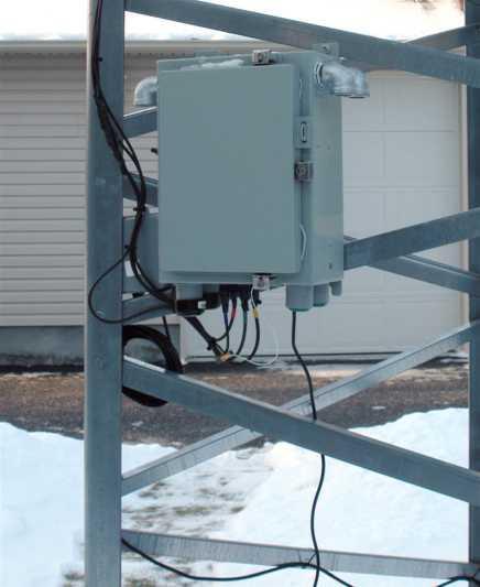
21 Moving to FN15vf VE3WCC Beacon enclosure hung on the tower with LDF2-50 dressed around mid-line of fence to mast on the south side

22 Moving to FN15vf Heliax formed into loop for ease of site maintenance access

23 Moving to FN15vf VE3WCC/B in operation next to Christie - Walther Pager Tower. Feedpoint elevation 485 ft ASL - same as at VE3XK

24 Moving to FN15vf The re-location team: Barney - VA3BGB, Andy - VE3NVK, Phil - VE3CIQ and Doug - VE3XK (with Tom - VE3ELM on camera)
25 Moving to FN15vf Additional Work Completed after the Move Installation of station identification EPROM programmed with Grid FN15vf identifier. Rebuild of Keyer Module to obtain 5 MS time constant on the P-Channel MOSFET keyer output. Replacement of UHF feed-through adapters with UHF Female bulkhead connectors, thus eliminating three coaxial adapters per band.
26 Moving to FN15vf The Results? Within the first day, Ken - VA3KA monitored a DX-spot stating that VE3WCC/b 6M beacon had been heard in Newfoundland. From FN15wg it had been heard in Florida, and 2M beacon heard south of Brantford near Lake Erie! Various WCARC members have reported hearing the other beacons - in some cases better than at the temporary initial location on the VE3XK tower. Better feedlines? Better location? Both? Ken - VA3KA reports that key clicks are gone now. Keep listening. Spread the word. We need more people listening to the beacons and more signal strength reports.
DIY. How to install a PL-259 connector. Parts list: Tools list: Worthwhile projects you can build on your own
 DIY Worthwhile projects you can build on your own Just like you, I often need to install a PL-259 connector on a length of coax (coaxial cable), to attach it to the mating SO-239 connector of a mobile
The Custom Interconnect Leader TM
 LC Series.5.188.685 ELECTRICAL Nominal Impedance: Frequency Range: Voltage Rating: Dielectric Withstanding Voltage: Insulation Resistance: VSWR: 50 ohms DC to 1.0 GHz 5,000 volts rms 3,000 volts rms 5,000
BTT rev. a Bob s TechTalk #8
 BTT rev. a Bob s TechTalk #8 Bob s TechTalk #8 by Bob Eckweiler, AF6C Coaxial Connectors: (Part I of III) UHF and N Connectors and MMCX/MCX Series. There are many other connectors that are less common
Automatic Connector MHV Connectors MHV Introduction MHV series connectors Contents Polarized mating interfaces Anti-Rock mating interfaces
 Automatic s 2004 Automatic. All rights reserved. pdf 1.0 3-18-04 Contents Specifications........................... 2 Straight Cable Plugs...................... 3 Right Angle Cable Plugs...................
QRO Coaxial Tee Fitting by WA4NJP, Ray Rector
 QRO Coaxial Tee Fitting by WA4NJP, Ray Rector There is a need for better, lower loss coaxial fittings. There is also a need for connectors that will handle more power. When we look at the everyday components
3M Distribution Box (DDB)
") 3M Distribution Box (DDB) Merged Copper and Fiber Pole/Post Mount Enclosure Installation Instructions November 2015 78-0015-2736-1-A 2 November 2015 78-0015-2736-1-A Contents 1.0 General 2.0 Enclosure
3M Distribution Box (DDB) Merged Copper and Fiber Pole/Post Mount Enclosure Installation Instructions November 2015 78-0015-2736-1-A 2 November 2015 78-0015-2736-1-A Contents 1.0 General 2.0 Enclosure
Type "N" Connectors. Type "N" Interface Dimensions
 Type "N" Connectors The type N series coaxial connectors were originally designed as medium-size low voltage constant impedance 50 OHM connectors. Type N connectors found immediate popularity for microwave
Solderless RF Connectors
 HF OPERATORS Solderless RF Connectors by John White VA7JW NSARC HF Operators 1 CenterPin Technology http://www.centerpin.com/ NSARC HF Operators 2 Connectors of Interest! 50 Ohm RF coax cable! PL-259 most
REQUIRED TOOLS. Wire cutters Razor blade Soldering iron Pliers 11/16 Wrench for Tube 18mm Wrench for Ring
 S9122 PWS BNC MALE CABLE MOUNT COMPRESSION CONNECTOR S9022 PWS N TYPE MALE CABLE MOUNT COMPRESSION CONNECTOR S9322 PWS TNC MALE CABLE MOUNT COMPRESSION CONNECTOR The PWS S9122 is a BNC male cable mount
DXE-UT-808X Coaxial Cable Stripping Tool
 DXE-UT-808X Coaxial Cable Stripping Tool DXE-UT-808X-INS-Revision 3b DX Engineering 2012 P.O. Box 1491 Akron, OH 44309-1491 USA Phone: (800) 777-0703 Technical Support and International: (330) 572-3200
Instructions. Cable with Armor F CAUTION. October Rev A
 3M Single Conductor Accessory Breakout Kits (BOK's) for use with 3M Cable Accessories (Terminations, T-Bodies and Push-On Elbows) For Use With Single Conductor Accessories On Three-Core Conductor Cables
SMA - 50 Ohm Connectors
 Alphabetical Index 142-0593-001 6 142-0593-006 6 142-0593-401 6 142-0593-406 6 142-0594-001 6 142-0594-006 6 142-0594-401 6 142-0594-406 6 142-0693-001 4 142-0693-006 4 142-0693-051 5 142-0693-056 5 142-0693-101
E4200 Antenna Installation Instructions: 1. Soldering required (here is the list of tools you will need)
") Thank you for purchasing the 6 Antenna Mod Kit for your Linksys router. First we will show you how to install the antennas for your router. Next we will teach you how to setup the DD-WRT firmware which
Thank you for purchasing the 6 Antenna Mod Kit for your Linksys router. First we will show you how to install the antennas for your router. Next we will teach you how to setup the DD-WRT firmware which
ASSEMBLY, INSTALLATION, AND REMOVAL OF CONTACTS AND MODULES
 ASSEMBLY, INSTALLATION, AND REMOVAL OF CONTACTS AND MODULES FOR 75 OHM AND 75 OHM HD COAXIAL CONTACTS AND MODULES Table of Contents SECTION 1 RECEIVER CONTACT ASSEMBLY INSTRUCTIONS SECTION 2 ITA CONTACT
ULTIMATE SNAP-N-SEAL
 ULTIMATE SNAP-N-SEAL F Series Compression Connectors Thomas & Betts introduces the Ultimate Snap-N-Seal Compression Connector, the newest addition to the Snap-N-Seal system. Look for the classic design
A449-6S 70 CENTIMETER FM YAGI ANTENNA MHz
 ASSEMBLY AND INSTALLATION A449-6S 70 CENTIMETER FM YAGI ANTENNA 440-450 MHz COMMUNICATIONS ANTENNAS 951425 (7/93) WARNING THIS ANTENNA IS AN ELECTRICAL CONDUCTOR. CONTACT WITH POWER LINES CAN RESULT IN
Coaxial Cable Termination
 Coaxial Cable Termination RF one-step BNC/TNC connectors Applications RF one-step BNC/TNC connectors are single-piece assemblies for terminating the center conductor and the braid of a broad range of coaxial
A CENTIMETER FM YAGI ANTENNA MHz
 ASSEMBLY AND INSTALLATION A449-70 CENTIMETER FM YAGI ANTENNA 440-450 MHz COMMUNICATIONS ANTENNAS 951424 (10/91) WARNING THIS ANTENNA IS AN ELECTRICAL CONDUCTOR. CONTACT WITH POWER LINES CAN RESULT IN DEATH
Assembly Instructions
 Assembly Instructions REP Series Environmentally - Sealed Rectangular Plastic Connectors Hypertac S.A. January 2014 Assembly Instructions REP Series January 2014 1 Table of Contents I. Introduction A.
Medium Box for Cable Termination
 FIST-MB2-T I N S T A L L A T I O N I N S T R U C T I O N Medium Box for Cable Termination Contents 1 Introduction 1.1 Product description. 2 General 2.1 Tools 2.2 Kit contents 3 Installation and pre assembling
SPECIAL SPECIFICATION 2344 TMC Support Equipment
 2004 Specifications CSJ 0912-00-488 SPECIAL SPECIFICATION 2344 TMC Support Equipment 1. Description. Furnish Traffic Management Center (TMC) support equipment in the City of Missouri City TMC location
FIST-MB2-S. FIST Medium Box for Cable Splicing Only. 4 Cable installation. 1 Introduction. Contents. 2 General. 5. Fiber routing to individual trays
 FIST-MB2-S I N S T A L L A T I O N I N S T R U C T I O N FIST Medium Box for Cable Splicing Only Contents 1 Introduction 1.1 Product description 2 General 2.1 Tools 2.2 Kit contents 3 Installation and
Coaxial Cable Feedline Choke Kit - 50 Ω
 Coaxial Cable Feedline Choke Kit - 50 Ω COM-CFC-50K COM-CFC-50K-INS-Revision 2a COMTEK SYSTEMS 2013 P.O. Box 1491 - Akron, OH 44309-1491 USA Phone: (800) 777-0703 Technical Support and International: (330)
ENGINEERING COMMITTEE Interface Practices Subcommittee AMERICAN NATIONAL STANDARD ANSI/SCTE
 ENGINEERING COMMITTEE Interface Practices Subcommittee AMERICAN NATIONAL STANDARD ANSI/SCTE 48-3 2011 Test Procedure for Measuring Shielding Effectiveness of Braided Coaxial Drop Cable Using the GTEM Cell
HN Connectors. Automatic Connector. Introduction. Contents. 631/ FAX 631/
 Connectors Introduction 2004 Automatic Connector. All rights reserved. pdf 1.0 4-13-04 Contents Specifications........................... 2 Straight Cable Plugs...................... 3 Right Angle Cable
Industrial Loadbreak Elbow
 Industrial Loadbreak Elbow 200 A 5, 8, and 15 kvclass 5810 Series Installation Instructions 1.0 General The 3M Industrial Loadbreak Elbow connector is a fullyshielded and insulated plug-in termination
Snail Fence InteleCell Deployment Guide
 Snail Fence InteleCell Deployment Guide Preparation 1. Prepare deployment trip by making sure you have the following materials and tools when you fly up to the site: InteleCell NEMA Enclsoure (grey plastic
Sections 1. Application Equipment 2. Cable Preparation 3. Assembly 4. Termination Procedure 5. Inspection 6. Repair 7.
 Page 1 of 6 Coaxial SolderSleeve Termination with Pre-Installed Wires or PCB Termination Body, B-044, B-043, B-041, B-040, B-020, B-021, B-046, D-148 Series Cable Type Typical RG Cable # -A- RG 178 RG
SECTION 7 -- CROSS-CONNECT SYSTEMS
 DETAIL ENGINEERING REQUIREMENTS AT&T March, 2016 Section 7, ATT-TP-76400 Revised NA SECTION 7 -- CROSS-CONNECT SYSTEMS CONTENTS PAGE 1. GENERAL... 7-2 1.1. Introduction... 7-2 1.2. Cable Holes... 7-2 1.3.
Multi-Media Installation Guide
 Multi-Media Installation Guide Coaxial Page 2 Data Plug Page 7 Data Jack Page 10 Telephone Page 13 Splicing Page 15 Cable Types Cable Types Two basic types of cable are used in multimedia installations.
MUK REAR PANEL ASSEMBLY ASSEMBLY INSTRUCTIONS
 Rev B. 13 August 2017 ASSEMBLY INSTRUCTIONS The Midnight Ultimate Keyer (MUK) consists of two functional assemblies: Rear Panel containing the interface and power connectors. Front Panel containing the
SMA One Piece Semi-Rigid Connectors
 SMA One Piece Semi-Rigid Connectors The Johnson captivated solderless contact connectors for semi-rigid cable provide a unique solution for high frequency cable assemblers. As compared to standard solder-on
RG-59/RG-6/RG-11 LSZH SERIES MAIN FEATURES
 RG-59/RG-6/RG-11 SERIES MAIN FEATURES ASTEL (Low Smoke Zero Halogen) series of RG-59/RG-6/RG-11 cables are latest addition to our range of coaxial cables. In Fire related incidents, smoke emission from
DL-AR2 Technical Specifications Universal HDMI Adapter Ring Rev
 DL-AR2 Technical Specifications Universal HDMI Adapter Ring Rev. 130814 The DL-AR2 Digital Adapter Keychain was developed to support the rising proliferation of mobile devices used in presentation systems.
3M Cold Shrink QS-III Silicone Rubber Splice Kit 5488A-TOW/WOT
 3M Cold Shrink QS-III Silicone Rubber Splice Kit 5488A-TOW/WOT For Tape Over Wire (TOW) and Wire-Over-Tape (WOT) Shielded Cable For 250 2000 kcmil cable with 650-mil primary insulation thickness Instructions
Table 4-1: Rating Levels
 OBJECTIVES 1. Describe various level ratings that apply to telecommunication cables and jacks and identify where each is implemented. 2. Describe the various levels of the cabling category rating systems.
Serial Digital BNC Connectors
 1 of 6 15/04/2009 15:21 Broadcast Catalog Serial Digital BNC Connectors Bomar s true 75 ohm BNC connectors fit all standard broadcast cables and utilize standard existing tooling. Made from precision machined
LEGEND POWER SYSTEMS
 S HEAT SHRINK JOINT 11kV 3 CORE Armoured XLPE/EPR Copper Wire screens STRAIGHT JOINT LEGEND POWER SYSTEMS Date 11 November 2014 Instruction Number PJJ006-14C PJJ006-14C Page 1 of 10 HEAT SHRINKABLE JOINT
LCC (Little Coaxial Connector) Installation Instructions)
 Installation Instructions)") LCC (Little Coaxial Connector) Installation Instructions) Content Page INTRODUCTION...1 Revision History...1 Trademark Information...1 1 TOOLS...2 1.1 Connection Tool Kit...2 1.2 Tool Illustrations...2
LCC (Little Coaxial Connector) Installation Instructions) Content Page INTRODUCTION...1 Revision History...1 Trademark Information...1 1 TOOLS...2 1.1 Connection Tool Kit...2 1.2 Tool Illustrations...2
Serial Digital BNC Connectors
 Broadcast Catalog Stock Check Distributor Serial Digital BNC Connectors Bomar s true 5 ohm BNC connectors fit all standard broadcast cables and utilize standard existing tooling. Made from precision machined
8D with High Frequency Coaxial Contact
 8D Series M Coaxial Contacts 8D with High Frequency Coaxial Contact robust and powerfull coaxial High Frequency transmission (M) now available in any size 8 SOURIU insert of D38999 Series III. Spring HF
SnapStak Stackable Snap-In Cable Hanger Electrical and Mechanical Testing Performance
 SnapStak Stackable Snap-In Cable Hanger Electrical and Mechanical Testing Performance Table of Contents Introduction................................1 Axial pull test and horizontal shear test............2
Non Magnetic Connectors
 Non Magnetic Connectors Johnson Components builds coaxial connectors using innovative materials and design to provide Mil Spec Performance at a commercial price. Now we offer our Non Magnetic Connectors
SCIR. Infrared Illuminator Powerful Indoor/Outdoor IR Spotlight SCIR
 SCIR Infrared Illuminator Powerful Indoor/Outdoor IR Spotlight The NetMedia SCIR Infrared (IR) Illuminator provides night vision for IR (850nm) sensitive cameras. It enables cameras such as NetMedia s
MCX Miniature Coaxial Connectors
 ONLINE CATALOG MCX Miniature Coaxial Connectors 104 John W. Murphy Drive P.O. Box 510 New Haven, CT 06513 www.aepconnectors.com e-mail: aepsales@aepconnectors.com Mating Interfaces MCX Miniature Coaxial
HAPPY HOLIDAYS PRESIDENTS NEXT MEETING SUNDAY DECEMBER 9 TH. CORNER.DECEMBER 2012 THE OFFICIAL NEWSPAPER OF THE YONKERS AMATEUR RADIO CLUB
 PRESIDENTS NEXT MEETING SUNDAY DECEMBER 9 TH. CORNER.DECEMBER 2012 THE OFFICIAL NEWSPAPER OF THE YONKERS AMATEUR RADIO CLUB HAPPY HOLIDAYS HARD TO BELIEVE THAT ANOTHER RENEW OR JOIN THE HOLIDAY PARTY IS
M2 Antenna Systems, Inc. Model No: 23CM35
 M2 Antenna Systems, Inc. Model No: 23CM35 SPECIFICATIONS: Model... 23CM35 Frequency Range... 1250 To 1300 MHz *Gain... 20.94 dbi Front to back... 25 db Typical Beamwidth... E=17 H=18 Feed type... Folded
ASSEMBLY AND INSTALLATION 3 ELEMENT 6 METER BEAM
 ASSEMBLY AND INSTALLATION A50-3S 3 ELEMENT 6 METER BM COMMUNICATIONS ANTENNAS 951364 (12/94) WARNING THIS ANTENNA IS AN ELTRICAL CONDUCTOR. CONTACT WITH POWER LINES CAN RESULT IN DTH, OR SERIOUS INJURY.
Digital Modulator Instructions
 Product Code: CCT818 ANTIhum.com Digital Modulator Instructions Features Tunable output channel from 21-69, Push button channel selection, Microprocessor tuning, Channel Memory, Audio input, LED channel
National Wire and Cable and National Cable Molding Headquarters Los Angeles California
 National Wire and Cable and National Cable Molding Headquarters Los Angeles California CAPABILITIES Medical Business Machines Communications Equipment Computer Equipment Audio Systems General Instrumentation
Quick Term III. 3M Cold Shrink 3 Core Indoor Termination. 3.3 kv mm 2
 Quick Term III 3M Cold Shrink 3 Core Indoor Termination Instruction Sheet All dimensions shown are mm unless otherwise stated Kit Contents 3 QT-III Termination Assembly 1 Cold Shrink Breakout Boot 3 Phase
Ultra-Grip Crimp Connector Hand Tool Kit for Coaxial Cable and Powerpole Connectors
 Ultra-Grip Crimp Connector Hand Tool Kit for Coaxial Cable and Powerpole Connectors DXE-UT-KIT-CRIMP DXE-UT-KIT-CRIMP-INS-Revision 2b DX Engineering 2014 1200 Southeast Ave - Tallmadge, OH 44278 USA Phone:
3M Cold Shrink Splice Kit QS-III 5515A
 3M Cold Shrink Splice Kit QS-III 5515A for UniShield, Wire Shielded, Longitudinally Corrugated (LC), and Tape Shielded (Ribbon Shielded) Cable or Transitions to Concentric Neutral (CN)/Jacketed Concentric
Cold Shrink Straight Joint
 Cold Shrink Straight Joint 3M QS2000E 22 kv Single Core Straight Joint Instruction Sheet All dimensions shown are in mm unless otherwise stated Kits contains components for one single core cable -2-2*
SUHNER QMA SUBMINIATURE CONNECTORS
 SUHNER QMA SUBMINIATURE CONNECTORS Description Content Page SUHNER QMA coaxial connectors are available with 50 Ω impedance. The frequency range extends to 11 GHz, depending on the connector and cable
ConnectAnywhere Prep Kit OEM INSTALLATION MANUAL
 Connectnywhere Prep Kit OEM INSTLLTION MNUL TBLE OF CONTENTS Introduction 2 Safety 2 Resources Required 3 Preparation 3 Installation 3 Notes 9 Introduction This document provides instructions for the installation
Ultra-Grip 2 Crimp Connector Hand Tool Kit for Coaxial Cable Connectors, Powerpole Connectors, Insulated and Non-Insulated Crimp Terminals
 Ultra-Grip 2 Crimp Connector Hand Tool Kit for Coaxial Cable Connectors, Powerpole Connectors, Insulated and Non-Insulated Crimp Terminals DXE-UT-KIT-CRMP2 DXE-UT-KIT-CRMP-INS-Revision 0a DX Engineering
Stainless Steel SMA Connectors Product Catalog
 Stainless Steel SMA Connectors Product Catalog Connectivity...for Stainless Steel SMA Connectors Connectivity...for Johnson Stainless Steel SMA Connectors meet or exceed the performance requirements of
White Paper. Discone Antenna Design
 White Paper Discone Antenna Design Written by Bill Pretty Highpoint Security Technologies Property of Highpoint Security Technologies Inc The user of this document may use the contents to recreate the
3 SLiC Aerial Closure with Rubber End Seal
 3 Aerial Closure with Rubber End Seal Instructions 1.0 General 1.1 This instruction bulletin describes the assembly of the 3M Aerial Closure with external bonding hanger brackets. These closures are suitable
INSTALLATION INSTRUCTION PEM1368ENG ENGLISH
 INSTALLATION INSTRUCTION PEM1368ENG 2015-01 ENGLISH COLD SHRINK HYBRID JOINT CJH11.42 FOR SINGLE CORE CABLES WITH Cu WIRE SHIELD Uo/U = 20.8/36 kv, Um = 42 kv 2/10 CJH11.42 PEM1368ENG 2015-01 GENERAL INFORMATION
Part Number (used with PRO-CRIMPER Tool Frame ) for 50 Ohm BNC Dual Crimp MIL Type Connectors
 for 50 Ohm BNC Dual Crimp MIL Type Connectors") Application Tooling Hand Tools CERTI-CRIMP Hand Tools are our top-of-the-line crimping tools featuring the original ratcheted crimp control. All tools are designed to exacting specifications, and manufactured
Application Tooling Hand Tools CERTI-CRIMP Hand Tools are our top-of-the-line crimping tools featuring the original ratcheted crimp control. All tools are designed to exacting specifications, and manufactured
Amphenol RF Connectors
 Amphenol RF Connectors 007 901-9601 SMA PLUGS & ANGLE PLUGS FOR FLEXIBLE CABLE 50X IMPEDANCE Conn. Attachment RG-/U Outer Inner 901-9511-12SF Dbl. Braid RG-316 Plug Br. Solder $17.49 901-9531-12SF Angle
Satellite Dish Installation Manual (Ver. 2) 1
 1") Satellite Dish Installation Manual Provided by DiscoverNet, Inc. Satellite Dish Installation Manual (Ver. 2) 1 Table of Contents Section 1: Introduction Page 3 Section 2: Recommended Tools and Materials
Satellite Dish Installation Manual Provided by DiscoverNet, Inc. Satellite Dish Installation Manual (Ver. 2) 1 Table of Contents Section 1: Introduction Page 3 Section 2: Recommended Tools and Materials
3M Cold Shrink Splice Kit QS-III 5514A
 3M Cold Shrink Splice Kit QS-III 5514A for UniShield, Wire Shielded, Longitudinally Corrugated (LC), and Tape Shielded (Ribbon Shielded) Cable or Transitions to Concentric Neutral (CN)/Jacketed Concentric
D-COAX, Inc. D-COAX d086 Series Cable Pair. High Frequency, Skew Matched, Phase Stable Cable Pair (65 GHz)
") D-COAX, Inc. D-COAX d086 Series Cable Pair High Frequency, Skew Matched, Phase Stable Cable Pair (65 GHz) D-COAX d086 Series Cable Pair consists of two skew matched (to 1ps) flexible cable assemblies with
D-COAX, Inc. D-COAX d086 Series Cable Pair High Frequency, Skew Matched, Phase Stable Cable Pair (65 GHz) D-COAX d086 Series Cable Pair consists of two skew matched (to 1ps) flexible cable assemblies with
BNC 75 Ohm RF-Connectors
 BNC 75 Ohm RF-Connectors Table of Contents BNC 75 Ohm 1/2 Page Company Profile... 3 Product Description... 4 Technical Data... 5 Design Options... 6 Connectors Cable Plug... 8 Adaptor... 12 U-Link... 14
 Register your product and get support at www.philips.com/welcome SDV8625T/27 User manual Contents 1 Important 4 Safety 4 For indoor use 4 For outdoor use 4 Notice for USA 4 Notice for Canada 5 Recycling
SERIES BNC 50, COAXIAL MINIATURE CONNECTORS
 SERIES BNC 50, COAXIAL MINIATURE CONNECTORS DESCRIPTION CONTENTS PAGE HUBER+SUHNER BNC is still one of the most popular connector series, featuring a two stud bayonet coupling mechanism, which is particularly
FIST-GCOG2-Dx6. Follow all local safety regulations related to optical fiber plant elements.
 FIST-GCOG2 I N S T A L L A T I O N I N S T R U C T I O N TC-986-IP Rev A, Mar 2017 www.commscope.com FIST-GCOG2-Dx6 Content 1 Introduction 2 General 2.1 Abbreviations 2.2 Kit contents 2.3 Tools 2.4 Accessories
 www.mete-enerji.com.tr INDUSTIAL IEC PLUGS AND SOCKETS INDUSTIAL IEC PLUGS AND SOCKETS Position of the Earthing Contact acc. to IEC 60309-2 225/400-265/460 V~ 60 Hz (1) 3 P+N+ 3 P+ 2 P+ 120/208-144/250V~
3M Cold Shrink QS4 Integrated Splice Kit QS4-35TS
 3M Cold Shrink QS4 Integrated Splice Kit QS4-35TS-350-1000 for Tape Shield, Wire Shield, UniShield, and Longitudinally Corrugated (LC) Cable Instructions IEEE Std. 404 35 kv Class 250 kv BIL F CAUTION
FOSC-450D. Fiber Optic Splice Closure. 1 Introduction. Content. 5 Cable termination. 6 Fiber routing. 2 General. 7 Installation of the gel block
 FOSC-450D I N S T A L L A T I O N I N S T R U C T I O N Fiber Optic Splice Closure Content 1 Introduction 2 General 2.1 Kit content 2.2 Tools 2.3 Accessories 2.4 Capacity 3 Preparation of the closure 4
3M Fiber Optic Splice Closure 2178-XL & 2178-XL/FR
 3M Fiber Optic Splice Closure 2178-XL & 2178-XL/FR 3M Cable Addition Kit 2181-XL and 2181-XL/FR Instructions September 2017 78-8130-5055-2-M 2 September 2017 78-8130-5055-2-M 1.0 Kit Contents 2.0 General...
Interface Practices Subcommittee AMERICAN NATIONAL STANDARD ANSI/SCTE
 Interface Practices Subcommittee AMERICAN NATIONAL STANDARD ANSI/SCTE 103 2018 Test Method for DC Contact Resistance, Drop cable to F connectors and F 81 Barrels NOTICE The Society of Cable Telecommunications
Build your own: Track Display
 Build your own: Track Display! " #! $% $ & ' $ ' ( ) * +, Track Display Manual 0706 web distribution version Table of Contents Section 1 Page 2 Quick Start Guide -Connecting 2 LEDs to Output #1 -Operating
Your Network Has Evolved. So Has Our Cable.
 Your Network Has Evolved. So Has Our Cable. Contents Introduction HELIAX 2.0... 3 HELIAX 2.0 Copper... 7 LDF4-50A (1/2 )... 8 AVA5-50 (7/8 )... 12 AVA6-50 (1-1/4 )... 16 AVA7-50 (1-5/8 )... 20 HELIAX 2.0
INTRODUCTION INSTALLATION LIGHTNING RETARDING LOOPS. Figure 1. Relay Box Antenna Connections. Relay Box Cable Connections
 INTRODUCTION The Ameritron RCS-8V is a remote controlled coaxial RF switch that will operate with negligible loss, radiation and VSWR at all frequencies up to 250 MHz. Only a slight compromise in VSWR
Installing a Wire Mesh Pulling Grip on All-Dielectric DX Armored Fiber Optic Cables
 revision history Issue Date Reason for Change Related literature SRP-004-136 Accessing All-Dielectric DX Armored Fiber Optic Cables Admonishments 1. General This procedure provides instructions for installing
Chapter 4. Dish Antenna Installation. Installing a DISH 500 Antenna. Finding the Satellites
 These instructions guide you through the installation of a satellite system which includes your receiver (included with this manual), and a DISH Pro DISH 500 antenna system that can be identified by the
HEXXAGONAL BEAM Mark 2
 HEXXAGONAL BEAM Mark 2 DXE-HEXX-5TAP-2, DXE-HEXX-1TAP-2 DXE-HEXX-BEAM-MARK2-INS Rev. 4e DX Engineering 2013 P.O. Box 1491 Akron, OH 44309-1491 USA Phone: (800) 777-0703 Tech Support and International:
Quick Term II. Cold Shrink Silicone Rubber Termination (With High-K Stress Relief) Instruction Sheet. Quick Term II. Silicone Rubber Termination Kits
 Instruction Sheet. Quick Term II. Silicone Rubber Termination Kits") Quick Term II Cold Shrink Silicone Rubber Termination (With High-K Stress Relief) Instruction Sheet IEEE Std. No. 48 1990 Class 1 Termination 15 kv Class 110 kv BIL Kit Contents: 3 Hi K Silicone Rubber
Quick Term II Cold Shrink Silicone Rubber Termination (With High-K Stress Relief) Instruction Sheet IEEE Std. No. 48 1990 Class 1 Termination 15 kv Class 110 kv BIL Kit Contents: 3 Hi K Silicone Rubber
Ultra Small Surface Mount Coaxial Connectors - Low Profile 1.9mm or 2.4mm Mated Height
 Ultra Small Surface Mount Coaxial Connectors - Low Profile 1.9mm or 2.mm Mated Height U.FL Series Up to 6GHz Transmission Speed Mated Height Comparison (With E.FL series) 1.9(2.0Max) U.FL-LP(V)-00 2.(2.5Max)
Mid-Span Access of Loose-Tube Ribbon Fiber Optic Cable
 Application Notes Mid-Span Access of Loose-Tube Ribbon Fiber Optic Cable Author Prasanna Pardeshi and Sudipta Bhaumik Issued November 2013 Abstract In fiber optic network, it is sometime necessary to splice
2178 Fiber Optic Splice Case and 2181 Cable Addition Kit
 2178 Fiber Optic Splice Case and 2181 Cable Addition Kit Instructions January 1994 Issue 1, 34-7029-6387-6 1 2 Contents: 1.0 General... 4 2.0 Specifications... 4 3.0 Kit Contents... 5 SECTION 1: 2178 Splice
QMA and QN connectors, patented products, become some real standard for the RF Telecommunications industry.
 CONTENTS PAGE Introduction...4-5 Characteristics... 6 Plugs...7-9 Jacks...9- Receptacles...-4 Adapters...4-6 Protective cap... 6 Panel drilling... 7 Receptacles packaging... 8 Assembly instructions...9-30
HOW TO USE THIS MANUAL
 HOW TO USE THIS MANUAL This manual is organized first by Antenna Specialists Cable groups and second by the types of RFI connectors available for those groups. The connectors are divided into subgroups
OCT 15 Rev B
 AMP+ HVA280-3pxm XE High-Voltage Plug Connector with 1-Stage Latching Application Specification 114-32125 15 OCT 15 Rev B NOTE All numerical values are in metric units [with U.S. customary units in brackets].
Installation Overview
 Installation Overview Overview This chapter presents cable preparation and installation procedures for coaxial cables. Many connectors and special-purpose installation tools required for these cables are
PERFORMANCE SPECIFICATION SHEET CONNECTORS, PLUGS, ELECTRICAL, COAXIAL, RADIO FREQUENCY (SERIES SMA (CABLED) - PLUG, PIN CONTACT, CLASS 2)
 - PLUG, PIN CONTACT, CLASS 2)") INCH-POUND MIL-PRF-39012/55G 6 February 2008 SUPERSEDING MIL-PRF-39012/55G 6 January 2006 PERFORMANCE SPECIFICATION SHEET CONNECTORS, PLUGS, ELECTRICAL, COAXIAL, RADIO FREQUENCY (SERIES SMA (CABLED) -
INCH-POUND MIL-PRF-39012/55G 6 February 2008 SUPERSEDING MIL-PRF-39012/55G 6 January 2006 PERFORMANCE SPECIFICATION SHEET CONNECTORS, PLUGS, ELECTRICAL, COAXIAL, RADIO FREQUENCY (SERIES SMA (CABLED) -
MPI Cable Selection Guide
 MPI Cable Selection Guide MPI engineers focus to provide on optimal cable solutions taking into account a number of requirements specific for wafer-level measurement systems: optimal cable length, cable
3M Cold Shrink QS-III Splice Kit 5467A(S)-WF
-WF") 3M Cold Shrink QS-III Splice Kit 5467A(S)-WF for Jacketed Concentric Neutral (JCN) Cable Instructions IEEE Std. 404 35 kv Class 250 kv BIL F CAUTION Working around energized systems may cause serious injury
3M Cold Shrink QS-III Splice Kit 5467A(S)-WF for Jacketed Concentric Neutral (JCN) Cable Instructions IEEE Std. 404 35 kv Class 250 kv BIL F CAUTION Working around energized systems may cause serious injury
VITALink Taped Splice Straight Through Crimp
 A Marmon Wire & Cable Berkshire Hathaway Company VITALink Taped Splice Straight Through Crimp 2 Hour Fire-Rated Splice VITALink MC Cables, UL FHIT 120 Installation Instructions Description The VITALink
If you have any problems please contact our office at Thank You! And Enjoy! Like us on Facebook /AllenLeighSC
 If you have any problems please contact our office at 204-728-8878 1-866-289-8164 Thank You! And Enjoy! Like us on Facebook /AllenLeighSC Follow us on Twitter @AllenLeighSC Also check out additional accessories
FOSC-600 C and D I N S T A L L A T I O N I N S T R U C T I O N
 FOSC-600 C and D I N S T A L L A T I O N I N S T R U C T I O N In-line and butt version Cold applied re-usable fiber optic closure Contents 1 Introduction 1.1 Product description 1.2 Capacity 2 General
Product Manual MNX10015 / REV C MODEL SB142, SB242. Dual Output Series Switch Boxes
 Product Manual MNX10015 / REV C MODEL SB142, SB242 Dual Output Series Switch Boxes Contents Section I Overview Introduction.... 2 Description... 2 Section II Installation Mounting... 3 Electrical Connections...
OFDC-B8-72. Outdoor fiber distribution closure. 6 Closing. Content 1 Introduction. 7 Re-entry. 2 Kit content. 3 Closure preparation
 OFDC-B8-72 I N S T A L L A T I O N I N S T R U C T I O N Outdoor fiber distribution closure Content 1 Introduction 2 Kit content 3 Closure preparation 4 Cable preparation 4.1 Feeder cable 4.2 Drop cable
ENGINEERING COMMITTEE Interface Practices Subcommittee SCTE Test Method for Cable Weld Integrity
 ENGINEERING COMMITTEE Interface Practices Subcommittee SCTE 178 2011 Test Method for Cable Weld Integrity NOTICE The Society of Cable Telecommunications Engineers (SCTE) Standards are intended to serve
Ultra-Grip 2 Crimp Connector Hand Tool Kit for Crimp Coaxial Cable Connectors, Powerpole Connectors, Insulated and Non-Insulated Crimp Terminals
 Ultra-Grip 2 Crimp Connector Hand Tool Kit for Crimp Coaxial Cable Connectors, Powerpole Connectors, Insulated and Non-Insulated Crimp Terminals DXE-UT-KIT-CRMP2 DXE-UT-KIT-CRMP-INS-Revision 0d DX Engineering
Reverse polarity connectors
 connectors Description According UL FCC (part 15.203) regulations, wireless radio equipment with removable antenna must not have a standardised interface. This to avoid the connection of antenna equipment