TABLE of CONTENTS. Item Description Page. 2.0 Simplified System Block Diagram 2
|
|
|
- Linette Martin
- 5 years ago
- Views:
Transcription
1 TABLE of CONTENTS Item Description Page General Simplified System Block Diagram The Path from Boeing Seal Beach to N6BOX Moreno Valley Calculate Signal at N6BOX at Various Tx Output Levels from 456 4,5,6 Boeing Building 5.0 N6BOX Repeater Test, Saturday February 14th, ,7 6.0 Modify Path loss numbers to reasonably match the test above 7,8,9 7.0 Calculate Signal levels from N6BOX at various distances toward 9,10,11 Boeing Building. Use the modified path loss numbers based on -150 db at 48.3 miles 8.0 What output power will be required at Boeing to overpower N6BOX 11 signal by 6 db at 10 miles from Boeing 9.0 At 5 watts output power, at what distance will we overpower N6BOX 12 from Boeing? 10.0 What happens at Irvine Park? 12, Conclusions 14 File: RacesRepDsgnDoc.pdf Page 1 of 14
2 1.0 General: This design is for a low level 440 Mhz repeater system for the Seal Beach/Los Alamitos RACES.The Repeater will be located on top of the Boeing Building on Seal Beach Blvd, specifically at 2201 Seal Beach Blvd., Building 80, Seal Beach, California GPS Coordinates are: 33 deg min N and 118 deg min W. The Antenna will be about 100 feet AGL (above ground level). Ground level at the location is about 30 feet +/- above sea level, mllw (mean low low water) That puts the antenna at about 130 feet above sea level. The repeater system will have an omini directional pattern, and will be designed to cover the cities of Seal Beach, Los Alamitos and most of Cypress. It will also cover the current unincorporated area known as Rossmoor. N6BOX operates a repeater on our selected frequency, Mhz, down 5 Mhz from Moreno Valley, approximately 48.3 statue miles away, on a 3000 foot mountain top with 50 watts repeater output power. Output power of the new RACES repeater will be limited to the power required to limit interference to N6BOX at 48.3 Statue Miles and still allow reliable communications within our desired coverage area. 2.0 Simplified System Block Diagram: 6.0 dbd Omni Directional Antenna 75 feet LMR 400 Coax LMR 400 Coax Duplexer LMR 400 Coax (85 db isolation) Transmitter Receiver (5 watts output) (.25 mv Sensitivity) Control Line Controller Control Line 120 VAC 120 VAC Back-up Telephone Control 120 VAC Input 13.8 vdc From Emergency Power System 13.8 vdc 13.8 Volt 13.8 vdc Battery Backup System File: RacesRepDsgnDoc.pdf Page 2 of 14


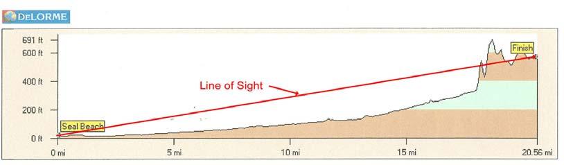
3 3.0 The Path from Boeing Seal Beach to N6BOX Moreno Valley Topo USA by DeLorme was used to develop the following plots: For all intensitive purposes this is a "Line of Sight Path". Very little "Knife Edge Refraction" occurs at 27 miles. File: RacesRepDsgnDoc.pdf Page 3 of 14
4 4.0 Calculate Signal at N6BOX at Various Tx Output Levels from Boeing Building Seal Beach RACES Transmitter Calculations Coax Loss: LMR 400 = 2.7 db/100 ft at 450 MHZ. At : 100 feet loss = 2.7 db Connector loss: Assume all Type"N" 4 at.1 db/ea = 0.4 db Duplexer Loss: 1.5 db Total loss (L)= 4.6 db Antenna System Gain in db, G = Antenna Gain - (L) Antenna Gain = 6.0 dbd (Hustler G6-440) Gain in dbi = Gain in dbd = 8.2 dbi Antenna System Gain (G)= db Gain N6BOX has Diamond X50 NA Antenna Antenna Gain = 7.2 dbi N6BOX has 120 feet of Andrews 7/8" Hardline Coax loss= 0.89 db (.74 db/100ft ) N6BOX Duplexer Loss (assumed) Duplexer loss= 1.5 db N6BOX Ant Sys= 4.81 db Gain Free space Path Loss is calculated as follows: Path Loss db = * log10 (freq in Mhz) + 20 x Log10 (distance in miles) This loss does not take into account atmospheric conditions such as atmospheric gases (oxygen & Water Vapor), Rain, Fog and Clouds which really don't come into play below 10 Ghz. What is the noise floor at N6BOX? In the absence of any detailed noise measurements, several assumptions will have to be made. First of all at 440 Mhz basic noise theory places the noise floor at roughly.35 microvolts or -116 dbm. Since this is a hilltop with many RF sources I'll assume we have at least 6 db of noise on top of that. That makes the noise floor at -110 dbm. Receiver sensitivity, typical, is.25 micro volts or -119 dbm. (9 db "headroom" seems reasonable). I'll assume anything less than -110 dbm won't be heard. Transmitter Output (PEP) PEP = 15 Watts EIRP (Watts) = transmitter output (PEP) x M EIRP= Watts dbm Signal Level at N6BOX is EIRP-Path Loss+N6BOX Ant Sys Signal Level= dbm > dbm Multiplying py factor M= 10^ G/10 M = Dimensionless so ess Transmitter Output (PEP) PEP = 10 Watts EIRP (Watts) = transmitter output (PEP) x M EIRP= Watts dbm Signal Level at N6BOX is EIRP-Path Loss+N6BOX Ant Sys Signal Level= dbm > dbm Transmitter Output (PEP) PEP = 9 Watts EIRP (Watts) = transmitter output (PEP) x M EIRP= Watts dbm Signal Level at N6BOX is EIRP-Path P Loss+N6BOX Ant Sys Signal Level= dbm > dbm File: RacesRepDsgnDoc.pdf Page 4 of 14
5 4.0 Continued Transmitter Output (PEP) PEP = 8 Watts EIRP (Watts) = transmitter output (PEP) x M EIRP= Watts dbm Signal Level at N6BOX is EIRP-Path Loss+N6BOX Ant Sys Signal Level= dbm > dbm Path loss= db at: 449 Mhz at: 48.3 miles Transmitter Output (PEP) PEP = 7 Watts EIRP (Watts) = transmitter output (PEP) x M EIRP= Watts dbm Signal Level at N6BOX is EIRP-Path Loss+N6BOX Ant Sys Signal Level= dbm > dbm Transmitter Output (PEP) PEP = 6 Watts EIRP (Watts) = transmitter output (PEP) x M EIRP= Watts dbm Signal Level at N6BOX is EIRP-Path Loss+N6BOX Ant Sys Signal Level= dbm > dbm Transmitter Output (PEP) PEP = 5 Watts EIRP (Watts) = transmitter output (PEP) x M EIRP= Watts dbm Signal Level at N6BOX is EIRP-Path Loss+N6BOX Ant Sys Signal Level= dbm > dbm Transmitter Output (PEP) PEP = 4 Watts EIRP (Watts) = transmitter output (PEP) x M EIRP= Watts dbm Signal Level at N6BOX is EIRP-Path Loss+N6BOX Ant Sys Signal Level= dbm > dbm Multiplying factor M= 10^ G/10 M = Dimensionless Transmitter Output (PEP) PEP = 3 Watts EIRP (Watts) = transmitter output (PEP) x M EIRP= Watts dbm Signal Level at N6BOX is EIRP-Path Loss+N6BOX Ant Sys Signal Level= dbm > dbm Transmitter Output (PEP) PEP = 2 Watts EIRP (Watts) = transmitter output (PEP) x M EIRP= Watts dbm Signal Level at N6BOX is EIRP-Path Loss+N6BOX Ant Sys Signal Level= dbm > dbm Transmitter Output (PEP) PEP = 1 Watts EIRP (Watts) = transmitter output (PEP) x M EIRP= Watts dbm Signal Level at N6BOX is EIRP-Path Loss+N6BOX Ant Sys Signal Level= dbm > dbm Path loss= db at: 449 Mhz at: 48.3 miles Transmitter Output (PEP) PEP = 0.5 Watts EIRP (Watts) = transmitter output (PEP) x M EIRP= Watts dbm Signal Level at N6BOX is EIRP-Path Loss+N6BOX Ant Sys Signal Level= dbm > dbm File: RacesRepDsgnDoc.pdf Page 5 of 14
6 4.0 Continued Transmitter Output (PEP) PEP = 0.25 Watts EIRP (Watts) = transmitter output (PEP) x M EIRP= Watts dbm Signal Level at N6BOX is EIRP-Path Loss+N6BOX Ant Sys Signal Level= dbm > dbm Path loss= db at: 449 Mhz at: 48.3 miles Transmitter Output (PEP) PEP = 0.10 Watts EIRP (Watts) = transmitter output (PEP) x M EIRP= Watts dbm Signal Level at N6BOX is EIRP-Path Loss+N6BOX Ant Sys Signal Level= dbm > dbm So it appears that we should be full quieting into the N6BOX Repeater even down to.10 Watt! That is not shown to be true from the tests conducted on February 14th, 2009, see below. 5.0 N6BOX Repeater Test, Saturday February 14th, 2009 Atmospheric conditions on the day of the test were ideal. Temperature around 64 degrees F, clear skies, Humidity around 40%, it had just rained the day before, no smog. Equipment Consisted of a Yaesu FT-736R transceiver, a Yaesu Power/SWR Meter,102 feet of new LMR-400 Coax, four (4) N connectors, a Hustler G6-440 Antenna (6 dbd Gain) and a portable Tripod for mounting the Antenna. The Antenna and Tripod were set on the Roof of the Boeing Building at approximately 130 Feet above sea level. Here are the results: 9:43 AM down 5 Mhz with a pl, antenna vertical Watts Report 4.0 Full Quieting Full Quieting 2.0 Minor white noise 1.0 White noise up a little 0.5 White noise at 4% 0.25 White noise at 50% 9:45 AM down 5 Mhz with a pl, antenna with downtilt Watts Report 1.0 Fair mmount of white noise % white noise 9.51 AM down 5 Mhz with no pl, antenna with downtilt, QSO with Alan Watts Report 4.0 Heard on input Heard on input 2.0 Heard on input File: RacesRepDsgnDoc.pdf Page 6 of 14
7 5.0 Continued 9:58 AM simplex, no pl, antenna with downtilt, N6BOX QSO with ham at Pomona Swap Meet Watts Report 4.0 No Interference 10.0 No Interference 20.0 No Interference No Interference 10:04 AM Test Complete 6.0 Modify Path loss numbers to reasonably match the test above For reliable communications (99%) the ARRL Antenna Book, Chapter 23, Figure 9, shows a free space terrestrial path loss of -178 db from Boeing Seal Beach to N6BOX Moreno Valley vs the db calculated from the above formula. We first heard white noise at about 2 watts out. Lets run the numbers again with a -150 db Path Loss Path loss= db at: 449 Mhz at: 48.3 miles Transmitter Output (PEP) PEP = 15 Watts EIRP (Watts) = transmitter output (PEP) x M EIRP= Watts dbm Signal Level at N6BOX is EIRP-Path Loss+N6BOX Ant Sys Signal Level= dbm > dbm File: RacesRepDsgnDoc.pdf Page 7 of 14
8 6.0 Continued Transmitter Output (PEP) PEP = 10 Watts EIRP (Watts) = transmitter output (PEP) x M EIRP= Watts dbm Signal Level at N6BOX is EIRP-Path Loss+N6BOX Ant Sys Signal Level= dbm > dbm Path loss= db at: 449 Mhz at: 48.3 miles Transmitter Output (PEP) PEP = 9 Watts EIRP (Watts) = transmitter output (PEP) x M EIRP= Watts dbm Signal Level at N6BOX is EIRP-Path Loss+N6BOX Ant Sys Signal Level= dbm > dbm Transmitter Output (PEP) PEP = 8 Watts EIRP (Watts) = transmitter output (PEP) x M EIRP= Watts dbm Signal Level at N6BOX is EIRP-Path Loss+N6BOX Ant Sys Signal Level= dbm > dbm Transmitter Output (PEP) PEP = 7 Watts EIRP (Watts) = transmitter output (PEP) x M EIRP= Watts dbm Signal Level at N6BOX is EIRP-Path Loss+N6BOX Ant Sys Signal Level= dbm > dbm Transmitter Output (PEP) PEP = 6 Watts EIRP (Watts) = transmitter output (PEP) x M EIRP= Watts dbm Signal Level at N6BOX is EIRP-Path Loss+N6BOX Ant Sys Signal Level= dbm > dbm Multiplying factor M= 10^ G/10 M = Dimensionless Transmitter Output (PEP) PEP = 5 Watts EIRP (Watts) = transmitter output (PEP) x M EIRP= Watts dbm Signal Level at N6BOX is EIRP-Path Loss+N6BOX Ant Sys Signal Level= dbm > dbm Transmitter Output (PEP) PEP = 4 Watts EIRP (Watts) = transmitter output (PEP) x M EIRP= Watts dbm Signal Level at N6BOX is EIRP-Path Loss+N6BOX Ant Sys Signal Level= dbm > dbm Transmitter Output (PEP) PEP = 3 Watts EIRP (Watts) = transmitter output (PEP) x M EIRP= Watts dbm Signal Level at N6BOX is EIRP-Path Loss+N6BOX Ant Sys Signal Level= dbm > dbm Path loss= db at: 449 Mhz at: 48.3 miles Transmitter Output (PEP) PEP = 2 Watts EIRP (Watts) = transmitter output (PEP) x M EIRP= Watts dbm Signal Level at N6BOX is EIRP-Path Loss+N6BOX Ant Sys Signal Level= dbm > dbm File: RacesRepDsgnDoc.pdf Page 8 of 14
9 6.0 Continued Transmitter Output (PEP) PEP = 1 Watts EIRP (Watts) = transmitter output (PEP) x M EIRP= Watts dbm Signal Level at N6BOX is EIRP-Path Loss+N6BOX Ant Sys Signal Level= dbm > dbm Path loss= db at: 449 Mhz at: 48.3 miles Transmitter Output (PEP) PEP = 0.5 Watts EIRP (Watts) = transmitter output (PEP) x M EIRP= Watts dbm Signal Level at N6BOX is EIRP-Path Loss+N6BOX Ant Sys Signal Level= dbm > dbm Transmitter Output (PEP) PEP = 0.25 Watts EIRP (Watts) = transmitter output (PEP) x M EIRP= Watts dbm Signal Level at N6BOX is EIRP-Path Loss+N6BOX Ant Sys Signal Level= dbm > dbm Transmitter Output (PEP) PEP = 0.10 Watts EIRP (Watts) = transmitter output (PEP) x M EIRP= Watts dbm Signal Level at N6BOX is EIRP-Path Loss+N6BOX Ant Sys Signal Level= dbm > dbm This path loss, -150db, seems about right for the conditions at the Test. It is also about 1/2 way between the free space Path Loss of db and the ARRL number of db. 7.0 Calculate Signal levels from N6BOX at various distances toward Boeing Building Use the modified path loss numbers based on -150 db at 48.3 miles N6BOX Transmitter Calculations Coax Loss: 7/8" Hardline.74db/100 ft at 450 Mhz : 120 feet loss = db Connector loss: Assume all Type"N" 4 at.1 db/ea = 0.4 db Duplexer Loss: 1.5 db Total loss (L)= db Antenna System Gain in db, G = Antenna Gain - (L) Antenna Gain = 7.2 dbi (Diamond X50NA) Antenna System Gain (G)= db Gain Path loss= db at: 449 Mhz at: 5 miles Signal Level is EIRP-Path Loss Signal Level= dbm Path loss= db at: 449 Mhz at: 10 miles Signal Level is EIRP-Path Loss Signal Level= dbm File: RacesRepDsgnDoc.pdf Page 9 of 14
10 7.0 Continued Path loss= db at: 449 Mhz at: 20 miles Signal Level is EIRP-Path Loss Signal Level= dbm Path loss= db at: 449 Mhz at: 30 miles Signal Level is EIRP-Path Loss Signal Level= dbm Path loss= db at: 449 Mhz at: 38 miles Signal Level is EIRP-Path Loss Signal Level= dbm Path loss= db at: 449 Mhz at: 39 miles Signal Level is EIRP-Path Loss Signal Level= dbm Path loss= db at: 449 Mhz at: 40 miles Signal Level is EIRP-Path Loss Signal Level= dbm Path loss= db at: 449 Mhz at: 41 miles Signal Level is EIRP-Path Loss Signal Level= dbm Path loss= db at: 449 Mhz at: 42 miles Signal Level is EIRP-Path Loss Signal Level= dbm Path loss= db at: 449 Mhz at: 43 miles Signal Level is EIRP-Path Loss Signal Level= dbm Path loss= db at: 449 Mhz at: 44 miles Signal Level is EIRP-Path Loss Signal Level= dbm File: RacesRepDsgnDoc.pdf Page 10 of 14
11 7.0 Continued Path loss= db at: 449 Mhz at: 45 miles Signal Level is EIRP-Path Loss Signal Level= dbm Path loss= db at: 449 Mhz at: 46 miles Signal Level is EIRP-Path Loss Signal Level= dbm Path loss= db at: 449 Mhz at: 47 miles Signal Level is EIRP-Path Loss Signal Level= dbm Transmitter Output (PEP) PEP = Watts Signal Level is EIRP-Path Loss Signal Level= dbm 8.0 What output power will be required at Boeing to overpower N6BOX signal by 6 db at 10 miles from Boeing? From the above Calculations the N6BOX signal at 38 miles away, is dbm. The Seal Beach RACES Repeater must have 6dB more power than this at 10 miles out or dbm For the Seal Beach RACES Boeing Building Repeater Coax Loss: LMR 400 = 2.7 db/100 ft at 450 MHZ. At : 100 feet loss = 27dB 2.7 Connector loss: Assume all Type"N" 4 at.1 db/ea = 0.4 db Duplexer Loss: 1.5 db Total loss (L)= 4.6 db Antenna System Gain in db, G = Antenna Gain - (L) Antenna Gain = 6.0 dbd (Hustler G6-440) Gain in dbi = Gain in dbd = 8.2 dbi Antenna System Gain (G)= db Gain Path loss= db at: 449 Mhz at: 10 miles Transmitter Output (PEP) PEP = 9.5 Watts EIRP (Watts) = transmitter output (PEP) x M EIRP= Watts dbm Signal Level at 10 miles out is EIRP-Path Loss Signal Level= dbm> dbm +6 db 9.0 At 5 watts output power, at what distance will we overpower N6BOX from Boeing? Path loss= db at: 449 Mhz at: 8 miles Transmitter Output (PEP) PEP = 5 Watts EIRP (Watts) = transmitter output (PEP) x M EIRP= Watts dbm Signal Level at 8 miles out is EIRP-Path Loss Signal Level= dbm> dbm + 6db File: RacesRepDsgnDoc.pdf Page 11 of 14


12 10.0 What happens at Irvine Park? The path from Seal Beach to Irvine Park is: File: RacesRepDsgnDoc.pdf Page 12 of 14


13 The path from Irvine Park to N6BOX is: First of all, there should be no problem interfering with N6BOX at Irvine Park due to Terrain features. Secondly we know that we can communicate to Irvine Park from Boeing with 5 watts and a beam antenna on the CERT Trailer.We also can communicate from my car with the Diamond Vertical Antenna, the same one that is now on the CERT trailer, so we should be good here. It looks like Irvine Park is a non issue and no calculations are required. File: RacesRepDsgnDoc.pdf Page 13 of 14
14 11.0 Conclusions The N6BOX repeater operates on 50 watts on top of a 3000 foot mountain on Mhz transmit and Mhz receive with a pl of hz. From the Test which was done on February 14th, and the calculations above, we will not cause interference if we use a different pl to pick up our new repeater. We'll use hz as our encode pl. If our Repeater is not transmitting, we will hear the N6BOX Repeater id'ing and any conversation. If our Repeater is transmitting we will not hear N6BOX out to about 10 miles from Boeing, assuming we set output power at 10 Watts. If we set our output power at 5 watts, then we will not hear N6BOX out to about 8 miles from Boeing. I suggest we start out with no decode pl on our radios to enable us to hear whats happening on Mhz. We can always put the decode pl on if it becomes a problem, but N6BOX is a very low usage Repeater and we shouldn't have a problem. File: RacesRepDsgnDoc.pdf Page 14 of 14
Lab Wireless Mathematics
 Lab 3.2.3 Wireless Mathematics Estimated Time: 25 minutes Number of Team Members: Students will work in teams of two or individually Objective In this lab, the student will learn the importance of the
TX70-.1s 70 CM ATV TRANSMITTER USERS MANUAL
 P. C. Electronics 2522 Paxson Lane Arcadia CA 91007-8537 USA 2014 Tel: 1-626-447-4565 m-th 8am-5:30pm pst (UTC - 8) Tom (W6ORG) & Mary Ann (WB6YSS) Web site: http://www.hamtv.com Email: ATVinfo @ hamtv.com
AT Active Iridium Antenna User Manual
 AT1621-20 Active Iridium Antenna User Manual This device complies with Part 15 of the FCC Rules. Operation is subject to the following two conditions: (1) this device may not cause harmful interfer ence
Namaste Project 3.4 GHz Interference Study Preliminary document - Work in Progress updated
 Namaste Project 3.4 GHz Interference Study Preliminary document - Work in Progress updated 05-29-08 The intent of this study is to collect data which may be used to help determine the noise floor expected
Transceiver Performance What s new in 2011?
 Transceiver Performance What s new in 2011? Rob Sherwood NCØ B Lots of options for your dollars. Sherwood Engineering What is important in a contest or DX pile-up environment? Good Dynamic Range to hear
Transceiver Performance What s new in the last year?
 Sherwood Engineering Transceiver Performance What s new in the last year? Rob Sherwood NCØB Lots of options for your dollars. What is important in a contest environment? Good Dynamic Range to hear weak
HORIZONTALLY POLARIZED OMNI COMPARISONS (490 MHz) [Ordered by Gmin in each Category.]
![HORIZONTALLY POLARIZED OMNI COMPARISONS (490 MHz) [Ordered by Gmin in each Category.]](/thumbs/96/127809737.jpg "HORIZONTALLY POLARIZED OMNI COMPARISONS (490 MHz) [Ordered by Gmin in each Category.]") HORIZONTALLY POLARIZED OMNI COMPARISONS (490 MHz) [Ordered by Gmin in each Category.] 13-Apr-16 holl_ands A. TRUE OMNI: [Roughly EQUAL GAIN in ALL Directions, preferably less than +/- 1 db] Gmin Gmax SWR
HORIZONTALLY POLARIZED OMNI COMPARISONS (490 MHz) [Ordered by Gmin in each Category.] 13-Apr-16 holl_ands A. TRUE OMNI: [Roughly EQUAL GAIN in ALL Directions, preferably less than +/- 1 db] Gmin Gmax SWR
Evaluation of New Hi-Des, Model HV-120A, DVB-T, Receiver Jim Andrews, KH6HTV
 p. 1 of 5 Application Note AN-27 copyright March, 2016 Evaluation of New Hi-Des, Model HV-120A, DVB-T, Receiver Jim Andrews, KH6HTV In the spring of 2014, I had become aware of the amateur DVB-T supplier,
RTX70-1s 70 CM ATV TRANSMITTER USERS MANUAL
 P. C. Electronics 2522 Paxson Lane Arcadia CA 91007-8537 USA 2008 Tel: 1-626-447-4565 m-th 8am-5:30pm pst (UTC - 8) Tom (W6ORG) & Mary Ann (WB6YSS) Web site: http://www.hamtv.com Email: ATVinfo @ hamtv.com
A. Section Includes: Division 1 applies to this section. Provide GPS wireless clock system, complete.
 SPECIFICATIONS GPS Wireless Clock System Section 16730 TIME SYSTEM PART 1 - GENERAL 1.01 SUMMARY A. Section Includes: Division 1 applies to this section. Provide GPS wireless clock system, complete. B.
User Manual. LPA_Tool. Prepared by: Customer Support. Date: November 25, 1999 WaveRider Document N o.: LPA_Tool User Manual_V2-0.
 User Manual LPA_Tool Prepared by: Customer Support. Date: November 25, 1999 WaveRider Document N o.: LPA_Tool User Manual_V2-0.doc Copyright 1999 WaveRider Communications Inc. Disclaimer The WaveRider
CABLE LOSS MASKING EFFECT
 CABLE LOSS MASKING EFFECT Masking Effect of Cable Loss on VSWR and Return Loss Measurements Jim Norton, Applications Engineer Bird Technologies Group Tel: 866.695.4569 / 592-APP-0905 613-APP-0905 Application
Project: IEEE P Working Group for Wireless Personal Area Networks (WPANs)
") Project: IEEE P802.15 Working Group for Wireless Personal Area Networks (WPANs) Title: [Radio Specification Analysis of Draft FSK PHY] Date Submitted: [11 March 2012] Source: [Steve Jillings] Company:
Project: IEEE P802.15 Working Group for Wireless Personal Area Networks (WPANs) Title: [Radio Specification Analysis of Draft FSK PHY] Date Submitted: [11 March 2012] Source: [Steve Jillings] Company:
Fibre Optic Modem ODW-622
 Fibre Optic Modem ODW-622 RS-232 to fibre optic link, redundant ring or multidrop applications The ODW-622 can be used to create either redundant ring or multidrop solutions for devices with RS-232 interfaces.
CYL-X7CAP-1 Small Cell Cantenna X-Pol, / MHz, 1FT
 X-Pol Small Cell Internally Duplexed Suitable for Pole or Building mount Dual Broadband Radiators Internal Beam combining Integrated Global Position System (GPS) option Includes Integrated Duplexers Requires
TX33-.1s 70 CM ATV TRANSMITTER USERS MANUAL
 P. C. Electronics 2522 Paxson Lane Arcadia CA 91007-8537 USA 2011 Tel: 1-626-447-4565 m-th 8am-5:30pm pst (UTC - 8) Tom (W6ORG) & Mary Ann (WB6YSS) Web site: http://www.hamtv.com Email: ATVinfo @ hamtv.com
By Jim Norton Bird Technologies Group Applications Engineer
 Introduction The masking effect of cable loss may cause your antenna to "appear" to perform more efficiently than is actually the case. In fact, it is possible to measure apparently acceptable or return
PAM-1840 Preamplifier Operation Manual
 PAM-1840 Preamplifier Operation Manual 1 TABLE OF CONTENTS INTRODUCTION 3 GENERAL INFORMATION 4 SPECIFICATIONS 4 OPERATING INSTRUCTIONS 5 MAINTENANCE 6 2 INTRODUCTION BEFORE APPLYING POWER Review this
Fibre Optic Modem ODW-611
 Fibre Optic Modem ODW-611 PROFIBUS DP to fibre optic link, point-to-point applications The ODW-611 is a fibre optic modem designed for point-to-point fibre optic connections between PROFI- BUS DP networks.
LONWORKS Fibre Optic Converter
 LONWORKS Fiber Optic Converter LRW-102 and LRW-102/PP LONWORKS to fibre optic link, multidrop and redundant ring applications The LRW-102 is a fibre optic modem designed for multidrop and redundant ring
SAL Series Wireless Clock (V1)
") SAL Series Wireless Clock (V1) HIGHLIGHTS Microprocessor based movement Each clock acts as a repeater and transmitter 915 928MHz frequency hopping technology Receiving and transmission rate every four
SAL Series Wireless Clock (V1) HIGHLIGHTS Microprocessor based movement Each clock acts as a repeater and transmitter 915 928MHz frequency hopping technology Receiving and transmission rate every four
TABLE OF CONTENTS RT-WAVE MOBILE RT-WAVE FIXED. 5.8GHz. 900MHz UHF OEM ACCESSORIES
 TABLE OF CONTENTS PROFILE 3 FEATURING 4 RT-WAVE MOBILE ALL WEATHER DIGITAL VIDEO SYSTEMS UP TO 6,000 FEET 6 ALL WEATHER DIGITAL VIDEO SYSTEMS UP TO 3 MILES 8 RT-WAVE FIXED ALL WEATHER DIGITAL VIDEO SYSTEMS
AW900mT. User s Manual. Point-to-multipoint. Industrial-grade, ultra-long-range 900 MHz non-line-of-sight wireless Ethernet systems
 User s Manual Point-to-multipoint Industrial-grade, ultra-long-range 900 MHz non-line-of-sight wireless Ethernet systems User s Manual Non-line-of-sight :: 900 MHz Thank you for your purchase of the multipoint
LONWORKS Fibre Optic Router
 LONWORKS Fiber Optic Router LRW-112 and LRW-112/PP LONWORKS to fibre optic link, multidrop and redundant ring applications The LRW-112 router offers an easy way to extend the distance between LONWORKS
JD725A Cable and Antenna Analyzer - Dual Port
 COMMUNICATIONS TEST & MEASUREMENT SOLUTIONS JD725A Cable and Antenna Analyzer - Dual Port Key Features Portable and lightweight handheld instrument Built-in wireless frequency bands as well as the most
ETSI/TC/SMG#30 TD SMG 582/99 Brighton, U.K. Agenda Item: November 1999
 /TC/SMG#30 TD SMG 582/99 Brighton, U.K. Agenda Item: 6.2 9-11 November 1999 Source: SMG2 CRs to GSM 03.30 (Antenna Test Method) Introduction : This document contains 1 CR to GSM 03.30 (strategic) agreed
ADDENDA COVER PAGE. The following Addenda have been currently released for this project, and are attached to this cover page:
 ADDENDA COVER PAGE The following Addenda have been currently released for this project, and are attached to this cover page: Addendum #1, 8/31/16 Addendum #2, 9/8/16 This cover sheet will reflect additional
Fibre optic router for TP/FT-10 LRW-112PP
 Fibre optic router for TP/FT-10 LRW-112PP Lo n Wo r k s to fibre optic link, point-to-point applications The LRW-112PP router offers an easy way to extend the distance between LONWORKS 78 kbit/s TP/FT
ELECTRICAL TESTING FOR:
 ELECTRICAL TESTING 0839.01 Hermon Laboratories Ltd. Harakevet Industrial Zone, Binyamina 30500, Israel Tel. +972-4-6288001 Fax. +972-4-6288277 E-mail: mail@hermonlabs.com TEST REPORT ACCORDING TO: FCC
FCC ID: IMK-ILCISA EMI TEST REPORT
 15.247 Certification FCC ID: IMK-ILCISA EMI TEST REPORT On SYMPHONY ISA Card Prepared for Proxim 295 N. Bernardo Ave Mountain View, CA 94043 Tel: (650)960-1630 Fax: (650)960-0332 Prepared by Electronic
PiMPro Portable Analyzer PiMPro Classic 1821
 DATA SHEET Highly accurate portable PIM Analyzer provides two 40 watt carriers (40W x 2), with -125 dbm sensitivity all in a less than 36 pound carry-on size case Instantaneous Measurement Modes for PIM
MAXTECH, Inc. BRC-1000 Series. C-Band Redundant LNB Systems. Technology for Communications. System Block Diagrams
 MAXTECH, Inc. Technology for Communications BRC-1000 Series C-Band Redundant LNB Systems Introduction Redundant LNB systems minimize system downtime due to LNB failure by providing a spare LNB and an automatic
Product model and standard
 Preface Thank you for purchasing the Ikan Blitz 400 HD Wireless Video System. This system features uncompressed high definition video with zero delay. Before using the product, please read this user s
December Spectrum Management and Telecommunications Policy
 December 2003 Spectrum Management and Telecommunications Policy A Staff Study on the Potential Impact of Satellite Digital Audio Radio Services Terrestrial Repeaters on Wireless Communications Service
ENGINEERING COMMITTEE
 ENGINEERING COMMITTEE Network Operations Subcommittee SCTE OPERATIONAL PRACTICE SCTE 222 2015 Useful Signal Leakage Formulas Title Table of Contents Page Number NOTICE 3 1. Scope 4 2. References 4 3. Abbreviations
Max EIRP below 921 MHz for GSM-R and LTE-R BS 28/11/2017
 Max EIRP below 921 MHz for GSM-R and LTE-R BS 28/11/2017 Objective: ensure coexistence with MFCN BS receiving below 915 MHz Criterion used: MFCN BS blocking level + duplexer additional filtering 2 Max
DATA SHEET. Two (2) fibers Detachable HDMI 2.0 Extender,
 fibers Detachable HDMI 2.0 Extender,") DATA SHEET Two (2) fibers Detachable HDMI 2.0 Extender, HDFX-300-TR Contents Description Features Applications Technical Specifications Operating Conditions Drawing of Module Drawing of Cable Connection
DATA SHEET Two (2) fibers Detachable HDMI 2.0 Extender, HDFX-300-TR Contents Description Features Applications Technical Specifications Operating Conditions Drawing of Module Drawing of Cable Connection
LAUREL. Laureate Digital Panel Meter for Load Cell & Microvolt Input ELECTRONICS, INC. Features. Description
 Description LAUREL ELECTRONICS, INC. Features Laureate Digital Panel Meter for Load Cell & Microvolt Input 20, 50, 100, 250 & 500 mv ranges Span adjust from 0 to ±99,999, zero adjust from -99,999 to +99,999
Microwave STL links. Full Duplex Ethernet bridges, up to 600mgbits. IP in to COFDM. Transmitter site. Router
 Microwave STL links. Full Duplex Ethernet bridges, up to 600mgbits Studio Transmitter site Microwave antennas will vary depending on the type of link TV programs multiplexed into IP transport stream Ethernet
Mmw radar solution for terrain awareness in UAVs ("1+2" solution)
") Mmw radar solution for terrain awareness in UAVs ("1+2" solution) Aimed at the flight environment of plant protection UAVs, Nanoradar has launched a millimeter-wave radar solution for terrain awareness
Mmw radar solution for terrain awareness in UAVs ("1+2" solution) Aimed at the flight environment of plant protection UAVs, Nanoradar has launched a millimeter-wave radar solution for terrain awareness
Link Budget Analysis for Broadband Services in IEEE b
 Link Budget Analysis for Broadband Services in IEEE 802.22b Authors: IEEE P802.22 Wireless RANs Date: 2012-07-17 Name Company Address Phone email Bingxuan Zhao Niigata University 8050 Igarashi 2-nocho,
RTC70-20S 70 cm ATV TRANSCEIVER USERS MANUAL
 P. C. Electronics 2522 Paxson Lane Arcadia CA 91007-8537 USA 2002 Tel: 1-626-447-4565 m-th 8am-5:30pm pst (UTC - 8) Tom (W6ORG) & Mary Ann (WB6YSS) O Hara 24 hr FAX order line 1-626-447-0489 Email: tomsmb@aol.com
Pro C Series MIMO LTE External IP67 Antenna
 Pro C Series MIMO LTE External IP67 Antenna Product Description Parsec s Pro C Series - PTA-PRO2C-2XLTE is a compact two-in-one MIMO LTE external waterproof M2M antenna. This rugged lowprofile omni-directional
CABLE TV on fiber. CABLE TV FIBERLINK Pass 100+ TV channels on 1 SingleMode fiber with no need for amps
 #FBS-870R-WALL-econ Reasonable prices, priceless reasoning. CABLE TV on fiber CABLE TV FIBERLINK Pass 100+ TV channels on 1 fiber with no need for amps Combine dozens of analog and digital channels in
PiMPro Rack Mount Analyzer
 DATA SHEET Highly accurate 19 inch rack mount PIM Analyzer provides two 40 watt carriers (40W x 2), with -125 dbm sensitivity all in a less than 36 pound carry-on size case Instantaneous Measurement Modes
EMC Test Report. Client: Continental Automotive Systems, Inc. Tested by: Fendy Liauw, Engineering Technician
 Test Report Number: 3953917EMC7 Rev: Page: 1 of 35 EMC Test Report Project Number: 3953917 Report Number: 3953917EMC7 Revision Level: Client: Continental Automotive Systems, Inc. Equipment Under Test:
PSM-2100L Satellite Modem L-Band IF Addendum
 DATUM SYSTEMS PSM-2100L Satellite Modem L-Band IF Addendum 1.0 Introduction Small receive only satellite stations have used L-Band as an outdoor to indoor equipment IF link for several years. The advent
1Chapter INTRODUCTION. This chapter describes the CST-5000 C-Band satellite terminal, referred to in this manual as the CST-5000 (Figure 1-1).
.") 1Chapter 1. INTRODUCTION This chapter describes the CST-5000 C-Band satellite terminal, referred to in this manual as the CST-5000 (Figure 1-1). Figure 1-1. CST-5000 Single Thread System Rev. 9 1 1 1.1
1Chapter 1. INTRODUCTION This chapter describes the CST-5000 C-Band satellite terminal, referred to in this manual as the CST-5000 (Figure 1-1). Figure 1-1. CST-5000 Single Thread System Rev. 9 1 1 1.1
5G New Radio Technology and Performance. Amitava Ghosh Nokia Bell Labs July 20 th, 2017
 5G New Radio Technology and Performance Amitava Ghosh Nokia Bell Labs July 20 th, 2017 1 Performance : NR @ sub 6 GHz 2 Motivation: Why 5G New Radio @ sub 6GHz Ubiquitous coverage for mmtc and URLLC Access
National Park Service Photo. Utah 400 Series 1. Digital Routing Switcher.
 National Park Service Photo Utah 400 Series 1 Digital Routing Switcher Utah Scientific has been involved in the design and manufacture of routing switchers for audio and video signals for over thirty years.
2W SDARS ECHO Repeater
 DATA SHEET Boosts SXM Signal Near WCS Sites Adjustable Gain to +93 db 2W High Power Output High Linearity Good Reverse Isolation High reliability ALC Protection Mounting Bracket accommodates mounting of
TEST REPORT FROM RFI GLOBAL SERVICES LTD
 FROM RFI GLOBAL SERVICES LTD Test of: Blighter B422-HPNB Aux Unit FCC ID: UFQB400HPNBAUX To: FCC Part 90: 2010 Subpart F in accordance with RFI Test Plan RFI/REGE1/TP75565JD03 Test Report Serial No: RFI-RPT-RP76945JD15B
2013 Price. Wireless Camera COFDM System
 Radiofar & Co Ltd. 75, Alba Iulia str. bl.7, Chisinau MD2071, Republic of Moldova Tel/fax: +373 22 620522 Tel.: +37322620533 E-mail: info@radio-far.com 2013 Price Part Wireless Camera COFDM System 1 Transmitter
N5264A. New. PNA-X Measurement Receiver. Jim Puri Applications Specialist March Rev. Jan Page 1
 New N5264A PNA-X Measurement Receiver Jim Puri Applications Specialist March 2009 Page 1 Rev. 1 N5264A Measurement Receiver No connectors on front panel Page 2 Rev. 2 N5264A PNA-X Measurement Receiver
DATA SHEET. Two (2) fibers Detachable DisplayPort 1.2 Extender, DPFX-200-TR
 fibers Detachable DisplayPort 1.2 Extender, DPFX-200-TR") DATA SHEET Two (2) fibers Detachable DisplayPort 1.2 Extender, DPFX-200-TR Contents Description Features Applications Technical Specifications Connection with DPAX Operating Conditions Drawing of Module
DATA SHEET Two (2) fibers Detachable DisplayPort 1.2 Extender, DPFX-200-TR Contents Description Features Applications Technical Specifications Connection with DPAX Operating Conditions Drawing of Module
Ku-Band Redundant LNB Systems. 1:1 System RF IN (WR75) TEST IN -40 db OFFLINE IN CONTROLLER. 1:2 System POL 1 IN (WR75) TEST IN -40 db POL 2 IN
 TEST IN -40 db OFFLINE IN CONTROLLER. 1:2 System POL 1 IN (WR75) TEST IN -40 db POL 2 IN") BRK-1000 Series Ku-Band Redundant LNB Systems Introduction Redundant LNB systems minimize system downtime due to LNB failure by providing a spare LNB and an automatic means of switching to the spare upon
BRK-1000 Series Ku-Band Redundant LNB Systems Introduction Redundant LNB systems minimize system downtime due to LNB failure by providing a spare LNB and an automatic means of switching to the spare upon
Cellular Signal Booster
 Drive G-M Cellular Signal Booster THE ALUMINUM CASING OF YOUR SIGNAL BOOSTER!! WILL ADJUST TO THE TEMPERATURE OF ITS ENVIRONMENT, BUT IS DESIGNED TO PROTECT THE SIGNAL BOOSTER TECHNOLOGY. FOR EXAMPLE,
ODW-621. RS-232 Point-to-point applications
 Re-timing Data rate up to 250 kbit/s 9-position D-sub connector Redundant power supply inputs Status interface for fault indication Fibre link fault indication (Red) Design for harsh environments 40 to
Pro C Series MIMO LTE, GPS and MIMO Dual Band Wi-Fi External IP67 Antenna. Product Description PTA PRO5C 2LTE 2WIFI GPS
 Pro C Series MIMO LTE, GPS and MIMO Dual Band Wi-Fi External IP67 Antenna Product Description Parsec s PRO C Series is a compact five-in-one MIMO LTE, MIMO Wi-Fi, and GNSS external waterproof M2M antenna.
Clarification for 3G Coverage Obligation Verification Data
 Clarification for 3G Coverage Obligation Verification Data Publication date: 7 June 2013 Contents Section Page 1 Introduction 1 2 Data Processing 3 3 Data Formatting 7 4 Data Validation 9 Annex Page 1
Pro C Series MIMO LTE External IP67 Antenna
 Pro C Series MIMO LTE External IP67 Antenna Product Description Parsec s Pro C Series is a compact two-in-one MIMO LTE external waterproof M2M antenna. This rugged lowprofile omni-directional antenna works
LT-82 Stationary IR Transmitter
 LT-82 Stationary IR Transmitter LT-82-0 (North America) LT-82-02 (Asia, UK) LT-82-03 (Euro) The Listen LT-82 is the heart of a stationary IR listening system. It takes the desired audio signal and transmits
HOW TO POINT A DISH ANTENNA
 HOW TO POINT A DISH ANTENNA A2.1 INSTALLING A SATELLITE DISH USING HD RANGER 2 A2.1.1 A bit of history That's it, a bit of history. First artificial satellite "Sputnik I" was launched 4th of October of
Multiple Band Outdoor Block Up- and Downconverters
 Multiple Band Outdoor Block Up- and Downconverters Vertical Mount Option RF IF LO Frequency Frequency Frequency Model Band (GHz) (MHz) (GHz) Number Block Upconverters 1 12.75 13.25 0.95 1.45 11.8 UPB2-WS-13.625
DA MHz Series of Narrowband or Wideband Distribution Amplifiers
 DA1-100-10-10MHz Series of Narrowband or Wideband Distribution Amplifiers Key Features 1-10 MHz wideband Operation. Other band frequencies from 100 khz to 200 MHz are available AGC Level Controlled. Output
i-repeater Control and monitor all your repeaters through the cloud Rackmount Wallmount
 i-repeater Control and monitor all your repeaters through the cloud Rackmount Wallmount Cloud control and monitoring Touch screen interface Alarms Statisics Details *Device = any repeater or line-amp Connection
DA : Series of Narrowband or Wideband Distribution Amplifiers
 DA1-100-10: Series of Narrowband or Wideband Distribution Amplifiers Key Features 1-100 MHz wideband Operation. Other band frequencies from 100 khz to 200 MHz are available AGC Level Controlled. Output
DATA SHEET. Two (2) fibers Detachable DisplayPort Extender, DPFX-100-TR
 fibers Detachable DisplayPort Extender, DPFX-100-TR") DATA SHEET Two (2) fibers Detachable DisplayPort Extender, DPFX-100-TR Contents Description Features Applications Technical Specifications Operating Conditions Drawing of Module Drawing of Cable Connection
DATA SHEET Two (2) fibers Detachable DisplayPort Extender, DPFX-100-TR Contents Description Features Applications Technical Specifications Operating Conditions Drawing of Module Drawing of Cable Connection
Contributions to SE43 Group 10 th Meeting
 Contributions to SE43 Group 10 th Meeting SE43(11)32 Further analisis on EIRP limits for WSDs SE43(11)33 Maximum EIRP calculation method Nokia Institute of Technology - INdT 1 Created in 2001 Nokia Institute
Rottweiler - Pro Series Low Profile 2 in 1 Antenna MIMO LTE External IP67 2 in 1 Low Profile Antenna. Product Description PTA PRO2R 2LTE
 Rottweiler - Pro Series Low Profile 2 in 1 Antenna MIMO LTE External IP67 2 in 1 Low Profile Antenna Product Description Parsec s PTA PRO2R 2LTE is an extremely low profile compact two-in-one MIMO LTE
R-1550A Tempest Wide Range Receiver
 R-1550A Tempest Wide Range Receiver Product Brochure Version 0.2.00 April 2008 Dynamic Sciences International, Inc. R-1550A TEMPEST Wide Range Measurement Receiver Made specifically for TEMPEST testing
A SLOW SCAN TV CONTACT ON 6 METERS
 A SLOW SCAN TV CONTACT ON 6 METERS The 5 th of November 2004 at 9PM. I decided to set up for my SSTV sched with Brad VK2JBC on 50.680Mhz USB. Brad and I had worked SSTV before between his old QTH and my
Critical Benefits of Cooled DFB Lasers for RF over Fiber Optics Transmission Provided by OPTICAL ZONU CORPORATION
 Critical Benefits of Cooled DFB Lasers for RF over Fiber Optics Transmission Provided by OPTICAL ZONU CORPORATION Cooled DFB Lasers in RF over Fiber Optics Applications BENEFITS SUMMARY Practical 10 db
Altum AC GHz PtP & PtmP License Free Wireless Ethernet Bridge Flexible & Rugged All Outdoor Design. System Features. Applications.
 5.1-5.9 GHz PtP & PtmP License Free Wireless Ethernet Bridge Flexible & Rugged All Outdoor Design Altum AC System Features 600 Mbps Layer 2 throughput Meets 5.15-5.25 GHz FCC rules 2x2 MIMO operation up
User Guide Supplement M4 ( MHz) CONTENTS UHF WIRELESS SYSTEM
 CONTENTS UHF WIRELESS SYSTEM") User Guide Supplement M4 (662-692 MHz) UHF WIRELESS SYSTEM CONTENTS SPECIFICATIONS... 2 FURNISHED ACCESSORIES... 5 OPTIONAL ACCESSORIES... 6 REPLACEMENT PARTS... 6 UHF WIRELESS SYSTEM COMPATIBILITY GUIDE...
User Guide Supplement M4 (662-692 MHz) UHF WIRELESS SYSTEM CONTENTS SPECIFICATIONS... 2 FURNISHED ACCESSORIES... 5 OPTIONAL ACCESSORIES... 6 REPLACEMENT PARTS... 6 UHF WIRELESS SYSTEM COMPATIBILITY GUIDE...
INSTALLATION MANUAL FT-FOTR-1VDE-ST-S
 INSTALLATION MANUAL FT-FOTR-1VDE-ST-S 1-Channel Digital Duplex Baseband Video Transmitter and Receiver With Reverse Data Transmission & Ethernet Transmission v1.0 4/5/11 1 PACKAGE CONTENTS This package
Models HP M n (WW) Access Point
 Access Point") Overview HP M210-802.11n Access Point Series Models HP M210 802.11n (AM) Access Point HP M210 802.11n (WW) Access Point JL023A JL024A Key features IEEE 802.11a/b/g/n access point (AP) Single-radio, dual-band
Overview HP M210-802.11n Access Point Series Models HP M210 802.11n (AM) Access Point HP M210 802.11n (WW) Access Point JL023A JL024A Key features IEEE 802.11a/b/g/n access point (AP) Single-radio, dual-band
SPECIAL SPECIFICATION :1 Video (De) Mux with Data Channel
 Mux with Data Channel") 1993 Specifications CSJ 0924-06-223 SPECIAL SPECIFICATION 1160 8:1 Video (De) Mux with Data Channel 1. Description. This Item shall govern for furnishing and installing an 8 channel digital multiplexed
1993 Specifications CSJ 0924-06-223 SPECIAL SPECIFICATION 1160 8:1 Video (De) Mux with Data Channel 1. Description. This Item shall govern for furnishing and installing an 8 channel digital multiplexed
Orbital Ka-ISO. Ext Ref Ka LNB with integrated isolator. Orbital Research Ltd Marine Drive, White Rock, BC. Canada V4B 1A9
 Orbital Ka-ISO Ext Ref Ka LNB with integrated isolator Orbital Research Ltd 14239 Marine Drive, White Rock, BC. Canada V4B 1A9 Part number generator Frequencies (GHz): LO Input Output Bandwidth 18.40F
SCALE & WEIGHT DISPLAYS
 The MICRO SERIES SCALE & WEIGHT DISPLAYS LARGE DIGIT MODELS Mighty-5S DPM MODELS Micro-S & Mighty-1S Mighty-1S Micro-S ELECTRO-NUMERICS, INC. Introduction The Electro-Numerics family of Digital Panel Meters
CPON-HFC. Customer Premises Optical Node for FTTH networks. About the Product
 About the Product The Light Link Direct CPON-HFC customer premises optical node for FTTH networks offers full-bandwidth cable television delivery, plus broadband access via DOCSIS cable modems. Fibre-to-the-home
11 GHz MDD FIBER OPTIC LINK FEATURES TYPICAL APPLICATIONS
 11 GHz MDD FIBER OPTIC LINK FEATURES Small size Bandwidth to 11 GHz Plug-in optical connector No external control circuits required Transimpedance amplifier in both transmitter and receiver Custom transmitter
DVO700 P FIBRE OPTIC TRANSMITTER
 Timo Rantanen September 24, 2002 1(5) FIBRE OPTIC TRANSMITTER is a high performance, extremely linear externally modulated 1550 nm transmitter for DVO fibre optic CATV link. This transmitter type has been
Datasheet. Carrier Backhaul Radio. Model: AF-2X, AF-3X, AF-5X. Up to 687 Mbps Real Throughput, Up to 200+ km Range
 Datasheet Carrier Backhaul Radio Model: AF-2X, AF-3X, AF-5X Up to 687 Mbps Real Throughput, Up to 200+ km Range 2.4, 3, or 5 GHz (Full-Band Certification including DFS) Ubiquiti s INVICTUS Custom Silicon
ТМ-04 Multichannel long range UHF alarm transmitter Operating manual. Sectron Ltd.
 Office: 52 G.M.Dimitrov blvd. 1125 Sofia tel: 02 91982 fax: 02 732576 TM-04 revision V1.0. ТМ-04 Multichannel long range UHF alarm transmitter Operating manual Sectron Ltd. www.sectron.com TM-04 description
Videolynx Bramble Bush Drive Gaithersburg, MD http: (240)
") Videolynx 19910 Bramble Bush Drive Gaithersburg, MD 20879 Videolynx@transmitvideo.com http: www.transmitvideo.com (240) 602-1082 Video-Lynx Z70A 70cm Mini Video/Audio Transmitter Only to be used by a licensed
Videolynx 19910 Bramble Bush Drive Gaithersburg, MD 20879 Videolynx@transmitvideo.com http: www.transmitvideo.com (240) 602-1082 Video-Lynx Z70A 70cm Mini Video/Audio Transmitter Only to be used by a licensed
Pro C Series MIMO LTE and Dual Band Wi-Fi External IP67 Antenna
 Pro C Series MIMO LTE and Dual Band Wi-Fi External IP67 Antenna Product Description Parsec s Pro C Series PTA PRO3C 2LTE WIFI is a compact threein-one MIMO LTE and Wi-Fi external waterproof M2M antenna.
db math Training materials for wireless trainers
 db math Training materials for wireless trainers Goals To understand why we use db to make calculations on wireless links. To learn db math. To be able to solve some simple exercises. To understand what
User manual. Long Range Wireless HDMI/SDI HD Video Transmission Suite
 User manual Long Range Wireless HDMI/SDI HD Video Transmission Suite Preface Thanks for purchasing our Long Range Wireless HDMI/SDI HD Video Transmission Suite. Before using this product, read this user
User s Guide TN-GB-SM512. Gigabit Interface Converter (GBIC) Transceiver Modules
 Transceiver Modules") Part Number TN-GB-MM5 TN-GB-ESX5 TN-GB-ESX6 TN-GB-SM5 TN-GB-SM53 TN-GB-SM55 TN-GB-SM58 TN-GB-SM512 User s Guide TN-GB-xM5x Gigabit Interface Converter (GBIC) Transceiver Modules The Transition Networks
Part Number TN-GB-MM5 TN-GB-ESX5 TN-GB-ESX6 TN-GB-SM5 TN-GB-SM53 TN-GB-SM55 TN-GB-SM58 TN-GB-SM512 User s Guide TN-GB-xM5x Gigabit Interface Converter (GBIC) Transceiver Modules The Transition Networks
NanoStation NanoStation. NanoStation. Compact, Hi-Power, 2x2 MIMO AirMax TDMA Station. *Respaldo y Garantía. Datasheet
 Compact, Hi-Power, 2x2 MIMO AirMax TDMA Station Models: NSM2, NSM3, NSM365, NSM5, LOCOM2, LOCOM5, LOCOM9 Cost Effective, Hi-Performance Compact and Versatile Design Powerful integrated Antenna *Respaldo
There are many ham radio related activities
 Build a Homebrew Radio Telescope Explore the basics of radio astronomy with this easy to construct telescope. Mark Spencer, WA8SME There are many ham radio related activities that provide a rich opportunity
Receiving DATV on four bands with Digital Satellite TV equipment
 Receiving DATV on four bands with Digital Satellite TV equipment By Grant VE3XTV Background: ATV started out on the 70 cm BAND using AM modulation and all contacts were made via simplex. The receivers
Requires half the number of feeder cables
 Antenna Systems Group CYL-X7CAP-1 Small Cell Cantenna, 698-896/1710-2170MHz, 1FT X-Pol Small Cell Internally Diplexed Suitable for Pole or Building mount Broadband Radiators Internal Beam combining Integrated
DA E: Series of Narrowband or Wideband Distribution Amplifiers
 DA1-150-10-E: Series of Narrowband or Wideband Distribution Amplifiers Key Features Dual A and B inputs. Automatic or manual switchover, configured by the Ethernet port. 1-150 MHz wideband operation. Other
Chihuahua PRO S Series Single Element LTE, Wi-Fi/Bluetooth/Zigbee, and GPS External IP67 Antenna
 Product Description Parsec s Chihuahua PRO S Series PTA PRO3S LTE WIFI GPS is a small footprint three-in-one cellular, Wi-Fi/Bluetooth/Zigbee, and GPS external waterproof antenna. This compact rugged omni-directional
MT32 Telemetry Multi channel telemetry system for rotating application
 Telemetrie-Messtechnik Schnorrenberg MT32 Telemetry Multi channel telemetry system for rotating application Up to 32 channel Sensor inputs for STG, POT, TH-K, Pt100, 4-20mV, ICP or VOLT STG - Auto Zero
Parabolic. Click Part Number for Datasheet. 25 ± 1 dbi 32.5 ± 1 dbi. GHz GHz GHz 32dBi
 Parabolic Click Part Number for Datasheet Part Number Description Frequency band Gain Polarization Dimension Antenna type Page MA-WP2556- DP12 Band Polarization Parabolic Reflector, 1.2m 2.4-2.7 GHz 5.0-6.0
DATV on ISS? How can this become a reality? Wolf-Henning Rech DF9IC / N1EOW Thomas Sailer HB9JNX / AE4WA
 DATV on ISS? How can this become a reality? Wolf-Henning Rech DF9IC / N1EOW Thomas Sailer HB9JNX / AE4WA UoS 8.2005 Wolf-Henning Rech DF9IC 1 Use open worldwide commercial broadcast standards - this ensures
ROUGH DRAFT. Guide. Installation. Signal Booster. Wilson. AG Pro 75 Smart Technology In-Building Wireless 800/1900 Signal Booster.
 Signal Booster Installation Guide Contents: AG Pro 75 Smart Technology In-Building Wireless 800/1900 Signal Booster Before Getting Started.... 1 Antenna Options & Accessories.................... 1 Easy