VP5DX October 2015
|
|
|
- Dinah Briggs
- 5 years ago
- Views:
Transcription

1 VP5DX October 2015 A brief description of the station is important for those that don t know. VP5DX is on the island of Middle Caicos in the Turks and Caicos Islands. The location is remote in that there are no stores, and no direct access to the outside world without traveling miles on the roads and a boat ride. This limits what is available for repairs and maintenance to what is on hand or what is brought with you there. The house is in a resort location and only the main tower and antenna can be left installed when the station is not being used. For the last few years the location has only been used during the CQWW phone contest in October. The main antenna on that tower is a 3 element SteppIr with the 30/40 meter dipole kit. This antenna was installed in 2008 and was taken down once for tower maintenance and the element poles were painted at that time. This was about 3 or 4 years ago. In early September of 2015 we received a picture from the neighbor saying that it looked like the antenna was broken and we might need to bring parts to repair it when we came in October.

2 I dropped a note to SteppIr and asked what I needed to make the repair. They needed to know which fiberglass elements we had as they have changed suppliers from time to time and the capacitance could be different. Lucky I found a picture of the element when we originally installed the antenna in 2008 blew it up and the label was visible. This SteppIr was a replacement for the previous 3 element that did not have the 30/40 meter kit and was damaged from a hurricane that took the tower down in September of A new tube was purchased and shipped to Providenciales for us to pick up on our trip. Upon arrival and settling in we proceeded to take the antenna down and make repairs. We had not spent any time in the radio shack at this point as there were no antennas to use anyway. When we leave the station after a contest there is a check list of things that are always, ALWAYS, done. Everything is unplugged from the ac power, any cables from the rotor, SteppIr control lines, any coax runs are removed from their respective control boxes. This includes retracting the elements on the antenna and leaving the rotor in the north position.

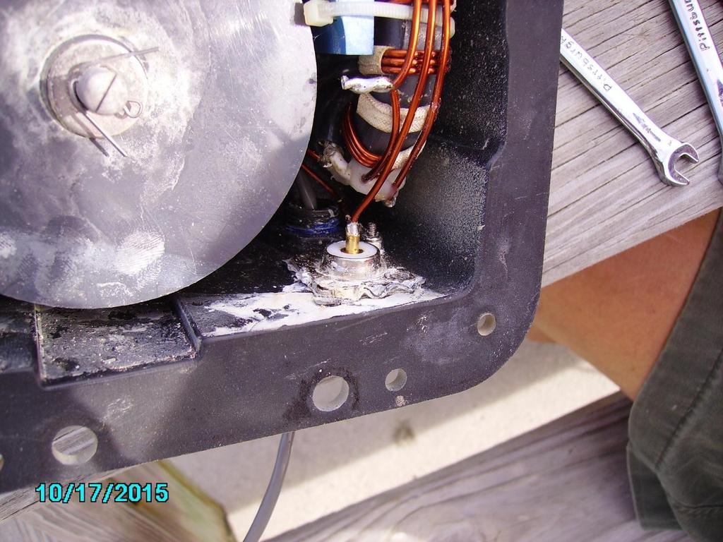
3 After lowering the antenna to the ground, here's what the tube looked like.

4 Also when removing the tubes, we found one of the tapes on the driven element was not retracted so I proceeded to go inside the shack plug in the SteppIr controller and park the elements. When I got inside and put power to the controller it did not come on. A quick check of the power supply showed it was dead. Also the control cable from the antenna had a burned mark on it. There was also a black mark from where the cable was laying not plugged in to anything to the case of the Icom 756 Pro and another black mark from that case to the case on the SteppIr control box. We knew at this moment that there is more to this operation than first thought. We had the power supply from the old SteppIr control box although it had not been seen for 7 years. After opening dozens of boxes in storage and finding that, the Control unit still did not power up. A couple of weeks before NF4L gave me a motor control PCB for this model control box and opening and inspecting found the regulator on our box was bad. The new pcb was installed and the box came up and appeared to be working. Of course it would not control the antenna as we needed to find a DB25 male connector to replace this one.

5 Before looking for a connector to replace this one with burned off pin at #1 I decided to check the resistance to the motors from this end of the cable. They were open on the couple I checked, and it was thought that maybe the cable was cut or blown open somewhere. All goes downhill from this point. No breaks were found in the control cable right up to the antenna. But during this inspection we did find the coax was missing about a foot of shield and its insulation.

6 I cut back the coax towards the shack about 2 feet and found the cable to be very clean and not damaged so a new connector was installed, and another new piece made to go up to the antenna with a PL-258. When we tried to remove the PL-259 from the driven element of the antenna this happened.

7 The shell of the PL-259 came off with the threads of the female completely. Well this could be fixed anyway. We took the EHU off the antenna and proceeded to put it on the picnic bench to make repairs. Opening the EHU found this damage.
8
9

10 The tapes are burned in half, both of them even though only one was not extended. Also notice the burned area on the end of the element that had not fully retracted. Ron hunted around and found the EHU from the old antenna and we made the decision to make this into a 20-6 meter antenna and we had enough parts to do that. The driven element EHU from the original antenna was not damaged and it was saved. The other 2 EHU s from that old antenna were destroyed when the tower had come down in 2008 and broken the housings. Of course when he went to remove the coax connector on the old EHU, the connector twisted off just like the other one.

11 Well the SO-239 was in stock in our cabinet so Ron proceeded to replace it.

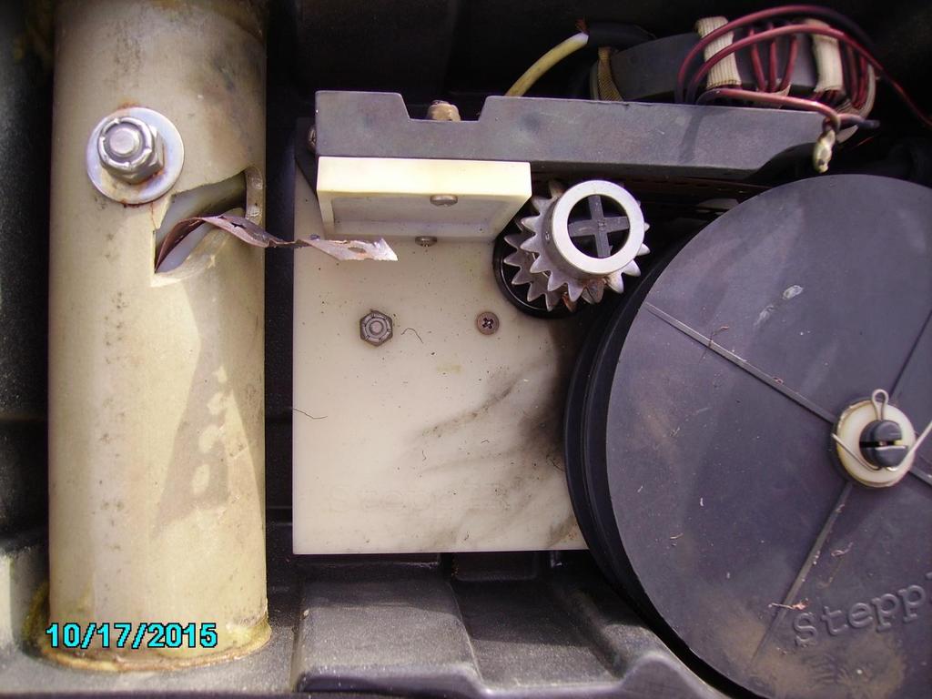
12 Ok we are making progress now. The new SO-239 installed, the control box is turning on, and we have tubes to install to make up at least a 20 6 meter antenna. I then tested the control box with this EHU to make sure all the motor ICs worked and all appeared to be ok. Now back to the control cable problem. I took the ohm meter out to the antenna to check the cables. I found that 3 of the other 4 windings on the stepper motors were open. We opened a stepper motor just to see what is inside.
 Well we are done, with the 2 other elements non-operational, we can make a rotatable dipole and that is about it. The SteppIR has had its last rites.")
13 The windings are burnt, along with the rotation unit. (Notice the end of the burnt tape on the bench) Well we are done, with the 2 other elements non-operational, we can make a rotatable dipole and that is about it. The SteppIR has had its last rites.. The Cushcraft A-4 was assembled and installed on the main tower. The SWR was dead flat as designed and the Yaesu G-1000 rotor worked, progress was being made. The next day in the morning Ron said the bands are really dead, he heard nothing on 20 meters. We had fired up the 2 windows 7 desktop computers that were purchased and installed in Neither would boot up. The power supply on one of them was bad, and the other the motherboard was bad. I managed to fix the power supply on that one, but its motherboard was bad also. We are dead here. We still had 2 old XP machines that these replaced and they would work. We need 3 machines to operate, one for each operating position and another upstairs to get to the Wi-Fi connection about 1/8 of a mile away. The shack is low to the ground and connection to the internet cannot get there from here. I normally talk to a few friends on 20 meters in the morning and had the radio sitting on the frequency we talk. I was trying to get the radio to communicate with the XP machine using WriteLog. All of a sudden the radio came to life and starting to receive. What was that??? We used the radio yesterday and it seemed ok, this morning no receive and all of a sudden it started to work. I deduced
 but the radio and the XP box still would not talk. During this we had turned off the Icom 756 Pro.")
14 that the IF-232 unit from the Icom to the computer not working. I opened the Icom interface box only to find a hole in the IC. I had another in stock and replaced it, (note: this was not in a socket) but the radio and the XP box still would not talk. During this we had turned off the Icom 756 Pro. It never received again, and is back up here in Florida for repair. Then the XP machine pressed into service at the Mult rig locked up and shut down. Inspection revealed that the Micro cooling fan was not running. Steve hunted around all the old stuff, (never throw anything away) and found a fan to fix that machine. During all of this one of the monitors was flickering so bad that Steve could not read it on the computer being used upstairs to get the internet. I took it apart and replaced a couple of capacitors and it got a lot better. I then went over and turned on the TS-950 on the other bench. It came on but no frequency display. Moving it away from the wall to open it up here is what we found. The white cable is a connector to the logic unit for the 10 position antenna switch; this logic unit was not connected to anything except another cable just like it over to the other operating position. The gray cable with the silver connector goes down to the filter box with 6 ¼ wave stubs in it. The black cable going out to the left goes to the interface unit on the Kenwood to a USB input on the computer. Here is the USB to RS-232 interface from the Kenwood.

15 Not very surprising that the Kenwood s micro is dead and the mother board on the computer it was plugged into was blown up also. So 2 radio s out of commission. We pulled out our other TS-950 that was still in its shipping box from We never took it out the box last year as we used the Icom instead of it. We also pressed the old TS-930 into service. No computer control on it so we would have to remember at least to change bands manually in the computer. We had an original Kenwood IF232 that was stored away and connected it to the XP machine. Never got it working reliable, the computer would either talk to the radio or the radio to the computer, and sometimes it worked both ways, never did figure that out. While sorting that stuff out the old Cushcraft A3 was installed. Back in 2013 this antenna did not work, Mike and I spent a whole day taking apart all the traps and cleaning and refurbishing them. It worked fine until during the contest the SWR went sky high and failed again. Of course it did not work now either. Mike and I started pulling apart the traps again, inspecting and cleaning as necessary. After pulling 3 of the 4 traps on the driven element apart and finding nothing that even was dirty or making a bad contact we almost stopped. When pulling apart the final 15 meter trap we found this.

16 The insulators were burned up and it was black from the arcs. We blew the antenna up during the contest. Might be too much power, or might have been moisture inside of it. We don t know but it might explain why one of the AL-1200 s band switches was burned up and had to be replaced in We repaired the trap, installed new insulators and the antenna works again. On Thursday before the contest Ron was working someone and I noticed the SWR was high on the A4 up on the main tower. A further check we found another place in the original coax that had been blown apart. Steve put some connectors on another run and replaced that. Then on Friday morning while on the air I pushed the monitor button on the TS-950 to see what the audio sounded like and the radio went dead. Opening it, I found the 7.5 amp blade fuse blown. It took 3 of us 2 hours to find the fuses that I was sure were there somewhere. Replaced the fuse, pushed the monitor button and it immediately blew again. Three hours later traced the problem to a connector miss installed on one of the boards. When I installed the roofing filter back in the summer of 2014 I must of mixed up 2 connectors. Well at least I figured it out. Well here is what we finally ended up with. Blown up: 2 desktop computers. Icom 756 pro. Icom interface. Kenwood TS-950. Kenwood to USB adapter. A router that was still connected to the computers. SteppIR antenna. SteppIR power supply.

17 One monitor quit about 2 hours into the contest. A few PL-259 connectors, and about 200 feet of coax. What we ended up working with. TS-950 with intermittent interface and an XP machine. TS-930 no interface and Ron s XP laptop. Both AL-1200s worked without a problem. The antennas, A-4 on the big tower, A-3 on the short tower, 80 meter delta loop, 160 meter inverted L, 40 meter vertical and low 10 meter 4 element. All the antennas had very, very low SWR and performed ok. Normally we have at least 2 antennas on every band. We just did not have enough time and energy to put up more. We did have 2 beverage antennas up, each about 600 feet long, one North west the other East. I felt some of my runs were not as fast as possible and Steve said low band operation was a real chore. Both of us blamed it on using the TS-930 not having the TS-950 with roofing filters and 1.8 bandwidth filters and DSP. After the contest I verified that the Digital unit was the flaw in the other TS-950 and brought that board home for repair. We also brought the Icom back for repair. Next year we will need new computers and 2 more monitors if not 3. Not sure if we are going to replace the mother boards or spend more money on a couple of laptops. Also we will need to return the Icom after it is fixed and repair the TS-950 that is still down there. Our claimed score was 11,473,587 for 2015 compared to 12,960,792 in Down a little, but we feel it was a pretty good effort considering.
18 Lesson learned. UNPLUG everything from everything, leave no cables attached to anything. And how much fun was that? 73 Jim NU4Y
SteppIR 20m Dipole Instruction Manual
 (Patent Pending) Yagi Dipole Vertical (Patented) SteppIR 20m Dipole Instruction Manual SteppIR Antennas 2112 116th Ave NE, Suite 2-5 - Bellevue, WA 98004 Tel: 425-453-1910 Fax: 425-462-4415 Tech Support:
RSL MusicPower Plug-In Installation Manual For Naim NAC 72 Preamp
 RSL MusicPower Plug-In Installation Manual For Naim NAC 72 Preamp (Updated to reflect the adjustable gain output boards Z200V) www.ryansoundlab.com RSL MusicPower Plug-In Installation Manual for Naim NAC
A449-6S 70 CENTIMETER FM YAGI ANTENNA MHz
 ASSEMBLY AND INSTALLATION A449-6S 70 CENTIMETER FM YAGI ANTENNA 440-450 MHz COMMUNICATIONS ANTENNAS 951425 (7/93) WARNING THIS ANTENNA IS AN ELECTRICAL CONDUCTOR. CONTACT WITH POWER LINES CAN RESULT IN
ASSEMBLY AND INSTALLATION 3 ELEMENT 6 METER BEAM
 ASSEMBLY AND INSTALLATION A50-3S 3 ELEMENT 6 METER BM COMMUNICATIONS ANTENNAS 951364 (12/94) WARNING THIS ANTENNA IS AN ELTRICAL CONDUCTOR. CONTACT WITH POWER LINES CAN RESULT IN DTH, OR SERIOUS INJURY.
A CENTIMETER FM YAGI ANTENNA MHz
 ASSEMBLY AND INSTALLATION A449-70 CENTIMETER FM YAGI ANTENNA 440-450 MHz COMMUNICATIONS ANTENNAS 951424 (10/91) WARNING THIS ANTENNA IS AN ELECTRICAL CONDUCTOR. CONTACT WITH POWER LINES CAN RESULT IN DEATH
TracVision R6DX Installation Guide
 TracVision R6DX Installation Guide These instructions explain how to install the TracVision R6DX satellite TV antenna system on an RV or motor coach. Complete instructions on how to use the system are
Wired Troubleshooting Manual
 Wired Troubleshooting Manual Congratulations on your choice of this product. Its superior sound reproduction will provide enjoyment and entertainment. We appreciate your patronage and take pride in the
LDG FT-Meter For Yaesu FT-857 and FT-897 Version 1.1
 LDG FT-Meter For Yaesu FT-857 and FT-897 Version 1.1 LDG Electronics 1445 Parran Road, PO Box 48 St. Leonard MD 20685-2903 USA Phone: 410-586-2177 Fax: 410-586-8475 ldg@ldgelectronics.com www.ldgelectronics.com
LDG M-7600 External Meter for Icom IC-7600
 M-7600 OPERATIONS MANUAL MANUAL REV A LDG M-7600 External Meter for Icom IC-7600 LDG Electronics 1445 Parran Road St. Leonard MD 20685-2903 USA Phone: 410-586-2177 Fax: 410-586-8475 ldg@ldgelectronics.com
Model Colorado Ultra Wide Bandwidth HDTV Matrix Switch
 HDTV Supply, Inc www.hdtvsupply.com Model Colorado Ultra Wide Bandwidth HDTV Matrix Switch Overview: This product is a full featured video & audio matrix switch. It is most commonly used to independently
Building the Highly-Versatile-Orange-Box (HVOB) go-kit
 go-kit") Building the Highly-Versatile-Orange-Box (HVOB) go-kit Perhaps you ve seen the article in QST and thought, Yeah, I need to build one of those! OK, here are the quick and dirty instructions on how to build
Building the Highly-Versatile-Orange-Box (HVOB) go-kit Perhaps you ve seen the article in QST and thought, Yeah, I need to build one of those! OK, here are the quick and dirty instructions on how to build
Bill of Materials: Super Simple Water Level Control PART NO
 Super Simple Water Level Control PART NO. 2169109 Design a simple water controller in which electrodes are required to sense high and low water levels in a tank. Whenever the water level falls below the
apple Service Source Apple Studio Display 17" LCD (ADC) Updated 6 Decenber Apple Computer, Inc. All rights reserved.
 Updated 6 Decenber Apple Computer, Inc. All rights reserved.") apple Service Source Apple Studio Display 17" LCD (ADC) Updated 6 Decenber 2004 2003 Apple Computer, Inc. All rights reserved. apple Service Source Take Apart Apple Studio Display 17" LCD (ADC) 2003 Apple
apple Service Source Apple Studio Display 17" LCD (ADC) Updated 6 Decenber 2004 2003 Apple Computer, Inc. All rights reserved. apple Service Source Take Apart Apple Studio Display 17" LCD (ADC) 2003 Apple
Lawnbott No Signal /Blackout Troubleshooting Guide
 The Lawnbott No Signal error can be the most difficult problem to resolve. There are two types of No Signal errors, persistent and intermittent. Persistent means the Lawnbott display shows No Signal as
40m - 30m Dipole Kit Instruction Manual for the Element Yagi
 Yagi Dipole Vertical (Patent #6,677,914) 40m - 30m Dipole Kit Instruction Manual for the 2-3-4 Element Yagi SteppIR Antennas 2112-116th Ave NE, Suite 2-5, Bellevue, WA 98004 Tel: 425-453-1910 Fax: 425-462-4415
Model CMX3838A2 AV Matrix Switch with DSP audio (firmware 1.0)
") Model CMX3838A2 AV Matrix Switch with DSP audio (firmware 1.0) Overview: This product is a full featured video & audio matrix switch. It is most commonly used to independently distribute video & audio
Model CMX3838A2 AV Matrix Switch with DSP audio (firmware 1.0) Overview: This product is a full featured video & audio matrix switch. It is most commonly used to independently distribute video & audio
DIN Connectors DIN06 E-03
 DIN Connectors DIN0 E-0 Contents Introduction HOSIDEN DIN connectors are supplied to electronic equipment manufacturers both in Japan and overseas and are very well accepted because of high quality, a
Table of Contents. Read This First.2. Introduction by Jim Fosgate...3. Unpacking..4. Tubes and Tube shield Installation 5. Product Placement...
 Owner s Manual Table of Contents Read This First.2 Introduction by Jim Fosgate...3 Unpacking..4 Tubes and Tube shield Installation 5 Product Placement...6 Connecting your Fosgate Signature..7 Phono stage
What is SnoCam? SnoCam Installation Guide. SolarVu
 4 1 2 3 4 5 6 7 8 D+ Rx- GND V+ GND V+ Power 1 2 3 4 5 6 7 8 9 10 What is? SolarVu Installation Guide SolarVu is an energy portal that enables remote monitoring of renewable energy generation sites over
Satellite Dish Installation Manual (Ver. 2) 1
 1") Satellite Dish Installation Manual Provided by DiscoverNet, Inc. Satellite Dish Installation Manual (Ver. 2) 1 Table of Contents Section 1: Introduction Page 3 Section 2: Recommended Tools and Materials
Satellite Dish Installation Manual Provided by DiscoverNet, Inc. Satellite Dish Installation Manual (Ver. 2) 1 Table of Contents Section 1: Introduction Page 3 Section 2: Recommended Tools and Materials
This Errata Sheet contains corrections or changes made after the publication of this manual.
 Errata Sheet This Errata Sheet contains corrections or changes made after the publication of this manual. Product Family: DL205 / DL305 Manual Number D2-DCM Revision and Date 2nd Edition; February 2003
How To: Replace the stock Antenna with a CB Antenna A CFans Members Mod Project by coyote
 How To: Replace the stock Antenna with a CB Antenna A CFans Members Mod Project by coyote Skill Level: Easy Disclaimer: Please use caution and seek professional assistance when necessary. ColoradoFans.com,
Introduction. The Clock Hardware. A Unique LED Clock Article by Craig A. Lindley
 Introduction As hard as it might be to believe, I have never built an electronic clock of any kind. I've always thought electronic clocks were passe and not worth the time to design and build one. In addition,
Connecting the Elecraft Power Combo to the Kenwood TS-2000 series Transceiver
 Connecting the Elecraft Power Combo to the Kenwood TS-2000 series Transceiver This Application Note describes how any model of the TS-2000 series transceiver can be connected the Elecraft Power Combo,
If you have any problems please contact our office at Thank You! And Enjoy! Like us on Facebook /AllenLeighSC
 If you have any problems please contact our office at 204-728-8878 1-866-289-8164 Thank You! And Enjoy! Like us on Facebook /AllenLeighSC Follow us on Twitter @AllenLeighSC Also check out additional accessories
Photos by N8IK (except first and last slide) 2015, Ian Keith, All Rights Reserved
 2015, Ian Keith, All Rights Reserved") I got in trouble at Hamvention this year. More trouble than I usually get into. I ordered a new K3S and a P3 panadapter from Elecraft. The usual crowd at the Elecraft booth looked like bears at a picnic.
I got in trouble at Hamvention this year. More trouble than I usually get into. I ordered a new K3S and a P3 panadapter from Elecraft. The usual crowd at the Elecraft booth looked like bears at a picnic.
GE CardioSoft (Version 6.01 or higher) Tango M2 Interface Notes
 Tango M2 Interface Notes") GE CardioSoft (Version 6.01 or higher) Tango M2 Interface Notes To setup Tango M2 with your CardioSoft (V6.01 or higher), simply follow the directions below. 1. Verify Correct RS-232 and ECG Trigger Cables
GE CardioSoft (Version 6.01 or higher) Tango M2 Interface Notes To setup Tango M2 with your CardioSoft (V6.01 or higher), simply follow the directions below. 1. Verify Correct RS-232 and ECG Trigger Cables
1x12 VGA & Audio over CAT5 Splitter
 SP-9112 1x12 VGA & Audio over CAT5 Splitter User Manual rev: 160322 Made in Taiwan Safety and Notice The SP-9112 1x12 VGA & Audio over CAT5 Splitter has been tested for conformance to safety regulations
USER MANUAL. 27 Full HD Widescreen LED Monitor L270E
 USER MANUAL 27 Full HD Widescreen LED Monitor L270E TABLE OF CONTENTS 1 Getting Started 2 Control Panel/ Back Panel 3 On Screen Display 4 Technical Specs 5 Care & Maintenance 6 Troubleshooting 7 Safety
USER MANUAL. 28" 4K Ultra HD Monitor L28TN4K
 USER MANUAL 28" 4K Ultra HD Monitor L28TN4K TABLE OF CONTENTS 1 Getting Started 2 Control Panel/ Back Panel 3 On Screen Display 4 Technical Specs 5 Care & Maintenance 6 Troubleshooting 7 Safety Info &
QRO Coaxial Tee Fitting by WA4NJP, Ray Rector
 QRO Coaxial Tee Fitting by WA4NJP, Ray Rector There is a need for better, lower loss coaxial fittings. There is also a need for connectors that will handle more power. When we look at the everyday components
VHF + UHF Amplified HDTV Antenna Model OA8000 & OA8001 Installation Instructions Reception Frequencies
 VHF + UHF Amplified HDTV Antenna Model OA8000 & OA8001 Installation Instructions Reception Frequencies VHF: 54-216 MHz UHF: 470-698 MHz FM: 87.9-107.9 MHz Voltage Input: AC110-120V / AC220-240V Working:
USER MANUAL. 22" Class Slim HD Widescreen Monitor L215DS
 USER MANUAL 22" Class Slim HD Widescreen Monitor L215DS TABLE OF CONTENTS 1 Getting Started Package Includes Installation 2 Control Panel / Back Panel Control Panel Back Panel 3 On Screen Display 4 Technical
Connecting the KPA500 to a Kenwood TS590s Transceiver
 Connecting the KPA500 to a Kenwood TS590s Transceiver The TS-590 does have a KEY OUT signal that will need to be connected to the KPA500's PA KEY jack. This 'arms' the KPA500 for transmit whenever the
OPERATION NOTES FOR PSIDEX AUDIO PGP-1A PRE-AMPLIFIER DESCRIPTION INSTALLATION
 OPERATION NOTES FOR PSIDEX AUDIO PGP-1A PRE-AMPLIFIER DESCRIPTION The Psidex Audio Laboratory PGP- 1A is a vacuum tube based microphone preamp and program line amplifier designed to provide solid, robust
Kramer Electronics, Ltd. USER MANUAL. Model: VS x 1 Sequential Video Audio Switcher
 Kramer Electronics, Ltd. USER MANUAL Model: VS-120 20 x 1 Sequential Video Audio Switcher Contents Contents 1 Introduction 1 2 Getting Started 1 2.1 Quick Start 2 3 Overview 3 4 Installing the VS-120 in
User Manual. Model 1372A and 1374A HDMI Switchers. 1T-SX-632 Model 1372A 2X1 Switcher. v1.3 2x1 SWITCHER. v1.3 INPUT ENHANCE POWER
 User Manual 1T-SX-632 Model 1372A 2X1 Switcher v1.3 v1.3 2x1 SWITCHER 1 2 INPUT ENHANCE POWER 1 2 INPUT ENHANCE POWER Model 1372A and 1374A HDMI Switchers Table Of Contents 1.0 Introduction.......................
DIY. How to install a PL-259 connector. Parts list: Tools list: Worthwhile projects you can build on your own
 DIY Worthwhile projects you can build on your own Just like you, I often need to install a PL-259 connector on a length of coax (coaxial cable), to attach it to the mating SO-239 connector of a mobile
A. Section Includes: Division 1 applies to this section. Provide GPS wireless clock system, complete.
 SPECIFICATIONS GPS Wireless Clock System Section 16730 TIME SYSTEM PART 1 - GENERAL 1.01 SUMMARY A. Section Includes: Division 1 applies to this section. Provide GPS wireless clock system, complete. B.
Warning and Safety Information. FCC Information
 Installation Manual Warning and Safety Information FCC Information This device complies with FCC Rules Part 15 Operation and is subject to the following two conditions: (1) This device may not cause harmful
APOLLO DESIGN TECHNOLOGY 4130 Fourier Drive Fort Wayne, IN USA Phone: Fax:
 APOLLO DESIGN TECHNOLOGY 4130 Fourier Drive Fort Wayne, IN 46818 USA Phone: +01.260.497.9191 Fax: +01.260.497.9192 www.apollodesign.net 07.26.10 Operating Manual [ Table of Contents ] Safety Information.
After Action Report - VOI Field Day 2018
 Event Overview After Action Report - VOI Field Day 2018 To work as many stations as possible on any and all amateur bands (excluding the 60, 30, 17, and 12-meter bands) and in doing so to learn to operate
V25 V25+ WS WS WS WS V27 WS-65517
 2005 Down to1 HIGH SPEED TROUBLESHOOTING V25-V27 CHASSIS V25 V25+ WS-48515 WS-55615 WS-55515 WS-65615 WS-65515 WS-73615 V25++ WS-55815 WS-65815 WS-55517 V27 WS-65517 WS-73517 MITSUBISHI DIGITAL ELECTRONICS
DISTRIBUTION AMPLIFIER
 MANUAL PART NUMBER: 400-0045-005 DA1907SX 1-IN, 2-OUT VGA/SVGA/XGA/UXGA DISTRIBUTION AMPLIFIER USER S GUIDE TABLE OF CONTENTS Page PRECAUTIONS / SAFETY WARNINGS... 2 GENERAL...2 GUIDELINES FOR RACK-MOUNTING...2
The Canned Ham By Bill Albert AD5TD
 The Canned Ham By Bill Albert AD5TD After sending the article about my Field Day experience to the South Texas ARES Yahoo Group, I had a request to publish some information and photos of my portable rig.
USER MANUAL. 27" 2K QHD LED Monitor L27HAS2K
 USER MANUAL 27" 2K QHD LED Monitor L27HAS2K TABLE OF CONTENTS 1 Getting Started 2 Control Panel/ Back Panel 3 On Screen Display 4 Technical Specs 5 Troubleshooting 6 Safety Info & FCC warning 1 GETTING
PROFESSIONAL 2 CHANNEL SOLID-STATE MIC / LINE PREAMPLIFIER USER S MANUAL
 PROFESSIONAL 2 CHANNEL SOLID-STATE MIC / LINE PREAMPLIFIER USER S MANUAL SAFETY INSTRUCTIONS This symbol, wherever it appears, alerts you to important operating and maintenance instructions in the accompanying
Regenerating Tissues
 Regenerating Tissues Exhibit Description: Regenerating Tissues is a stand-alone interactive component of the Nanomedicine exhibition. A copy panel describes how Nanomaterials are able to form tiny structures
Transceiver Performance What s new in the last year?
 Sherwood Engineering Transceiver Performance What s new in the last year? Rob Sherwood NCØB Lots of options for your dollars. What is important in a contest environment? Good Dynamic Range to hear weak
WiFi Interface Identifier from RF Industries
 WiFi Interface Identifier from RF Industries Today s wireless market has exposed us to many new, and some familiar connectors. The wide range of antennas, access points, routers, WLAN s, cellular devices,
Cellular Signal Booster
 Connect 4G-X Cellular Signal Booster !! IT IS VERY MPORTANT TO POWER YOUR SIGNAL BOOSTER US NG A SURGE PROTECTED AC POWER STRIP WITH AT LEAST A 1000 JOULE RATING. FAILURE TO DO THIS WILL VOID YOUR WARRANTY
TECHNICAL SUPPORT , or FD151CV-LP Installation and Operation Manual 15.1 Low Profile LCD
 TECHNICAL SUPPORT 678-867-6717, or www.flightdisplay.com FD151CV-LP Installation and Operation Manual 15.1 Low Profile LCD FD151CV-LP 15.1" Low Profile LCD 2006 Flight Display Systems. All Rights Reserved.
E4200 Antenna Installation Instructions: 1. Soldering required (here is the list of tools you will need)
") Thank you for purchasing the 6 Antenna Mod Kit for your Linksys router. First we will show you how to install the antennas for your router. Next we will teach you how to setup the DD-WRT firmware which
Thank you for purchasing the 6 Antenna Mod Kit for your Linksys router. First we will show you how to install the antennas for your router. Next we will teach you how to setup the DD-WRT firmware which
PLL2210MW LED Monitor
 PLL2210MW LED Monitor USER'S GUIDE www.planar.com Content Operation Instructions...1 Safety Precautions...2 First Setup...3 Front View of the Product...4 Rear View of the Product...5 Quick Installation...6
Coaxial Cable Feedline Choke Kit - 50 Ω
 Coaxial Cable Feedline Choke Kit - 50 Ω COM-CFC-50K COM-CFC-50K-INS-Revision 2a COMTEK SYSTEMS 2013 P.O. Box 1491 - Akron, OH 44309-1491 USA Phone: (800) 777-0703 Technical Support and International: (330)
RoHS. Atma-Sphere Music Preamplifier. model P-2 OWNER'S MANUAL. Please study this document carefully before using equipment
 1742 Selby Av. St. Paul, MN 55104 651 690 2246 atma sphere.com Atma-Sphere Music Preamplifier model P-2 OWNER'S MANUAL Please study this document carefully before using equipment RoHS CONGRATULATIONS!
Modifying the RW1127 and similar TWTs for 24GHz
 Modifying the RW1127 and similar TWTs for 24GHz Some notes by Brian G4NNS updated after the EME conference. Issue 1.04 During a visit from Johannes DF1OI he explained how Ulli DK3UC had modified Siemens
Cellular Signal Booster
 Drive 4G-X Cellular Signal Booster THE ALUMINUM CASING OF YOUR SIGNAL BOOSTER!! WILL ADJUST TO THE TEMPERATURE OF ITS ENVIRONMENT, BUT IS DESIGNED TO PROTECT THE SIGNAL BOOSTER TECHNOLOGY. FOR EXAMPLE,
Telemetry Receiver Installation Guide
 BBV Telemetry Receiver Installation Guide Models covered Rx200 Building Block Video Ltd., Unit 1, Avocet Way, Diplocks Industrial Estate, Hailsham, East Sussex, UK. Tel: +44 (0)1323 842727 Fax: +44 (0)1323
Modifying the Icom IC 7000 Export version No 8 to receive PAL TV in South Africa and to open up the TX frequency range.
 Modifying the Icom IC 7000 Export version No 8 to receive PAL TV in South Africa and to open up the TX frequency range. Gary Immelman ZS6YI In South Africa the TV audio frequency is different to that used
TS-590S Issues and Suggestions
 TS-590S s and s 29 July 2013 1 TS-590S s and s This document contains a list of issues and suggestions to improve the functionality and operation of the TS-590S, for the attention of Kenwood. If you would
PL2410W LCD Monitor USER'S GUIDE.
 PL2410W LCD Monitor USER'S GUIDE www.planar.com Content Operation Instructions...1 Safety Precautions...2 First Setup...3 Front View of the Product...4 Rear View of the Product...5 Quick Installation...6
USER MANUAL. 27 Full HD Widescreen LED Monitor L27ADS
 USER MANUAL 27 Full HD Widescreen LED Monitor L27ADS TABLE OF CONTENTS 1 Getting Started 2 Control Panel/ Back Panel 3 On Screen Display 4 Technical Specs 5 Care & Maintenance 6 Troubleshooting 7 Safety
Chapter 4. Dish Antenna Installation. Installing a DISH 500 Antenna. Finding the Satellites
 These instructions guide you through the installation of a satellite system which includes your receiver (included with this manual), and a DISH Pro DISH 500 antenna system that can be identified by the
SAFETY INFORMATION. 7. Do not force switched or external connections in any way. They should all connect easily, without needing to be forced.
 SAFETY INFORMATION 1. To ensure the best results from this product, please read this manual and all other documentation before operating your equipment. Retain all documentation for future reference. 2.
Welch Allyn CardioPerfect Workstation Tango+ Interface Notes
 Welch Allyn CardioPerfect Workstation Tango+ Interface Notes To setup Tango+ with the CardioPerfect stress system, simply follow the directions below. 1. Verify Correct RS-232 and ECG Trigger Cables RS-232
Concert Series ORDERCODE D3470 ORDERCODE D3471 ORDERCODE D3472 D3470 D3471 D3472
 Concert Series ORDERCODE D3470 ORDERCODE D3471 ORDERCODE D3472 D3470 D3471 D3472 Congratulations! You have bought a great, innovative product from DAP Audio. The DAP Audio Concert Series brings excitement
VGA CAT-5 1:8 Distribution S VGA CAT-5 Distribution R. EXT-VGA-CAT5-148S EXT-VGA-CAT5-148R User Manual
 VGA CAT-5 1:8 Distribution S VGA CAT-5 Distribution R EXT-VGA-CAT5-148S EXT-VGA-CAT5-148R User Manual INTRODUCTION Congratulations on your purchase of the VGA CAT-5 1:8 Distribution S. Your complete satisfaction
ST-CCTV-VBAC 1 Channel UTP Active Video Balun Transceiver
 INSTALLATION MANUAL ST-CCTV-VBAC 1 Channel UTP Active Video Balun Transceiver Copyright North American Cable Equipment, Inc. 1 PACKAGE CONTENTS This package contains: One ST-CCTV-VBAC-TX Active Video Transmitter
NewScope-7A Operating Manual
 2016 SIMMCONN Labs, LLC All rights reserved NewScope-7A Operating Manual Preliminary May 13, 2017 NewScope-7A Operating Manual 1 Introduction... 3 1.1 Kit compatibility... 3 2 Initial Inspection... 3 3
MS2540 Current Loop Receiver with RS485 Communication
 MS2540 Current Loop Receiver with RS485 Communication User Manual Metal Samples Company A Division of Alabama Specialty Products, Inc. 152 Metal Samples Rd., Munford, AL 36268 Phone: (256) 358 4202 Fax:
Identification - electrical services
 Identification - electrical services Aesthetic All live phase cable sheathing to be brown coloured and neutral phase cable sheathing to be blue coloured, all labelled L1, L2, L3 & N respectively in accordance
INSTALLATION MANUAL. ST-CVTMD420-WPIR-W Covert Motion Detection Color Camera. v1.3 8/11/11 1
 INSTALLATION MANUAL ST-CVTMD420-WPIR-W Covert Motion Detection Color Camera v1.3 8/11/11 1 PACKAGE CONTENTS This package contains: One ST-CVTMD420-WPIR-W covert motion detection camera One installation
Hardware Guide BrightSign, LLC Version:.1 Los Gatos, CA, USA. MODELS: XD Product Line
 Hardware Guide BrightSign, LLC Version:.1 Los Gatos, CA, USA MODELS: XD Product Line Contents Overview... 1 Block Diagram... 2 Ports... 2 XD230... 2 XD1030... 2 XD1230... 3 Power Connector... 3 Ethernet...
Installing a MotoSat MD500 for Dish Network on a RB Born Free
 Installing a MotoSat MD500 for Dish Network on a 2005 24RB Born Free 1 2005 24RB July 2006 I have Dish network using satellites 110 and 119 and had decided on using the MotoSat MD500 rather than the dome
COHERENCE ONE PREAMPLIFIER
 COHERENCE ONE PREAMPLIFIER OWNER S MANUAL TABLE OF CONTENTS Introduction Features Unpacking Instructions Installation Phono Cartridge Loading Basic Troubleshooting Technical Specifications Introduction
PARTS LIST FOR CM-1250-A/C 1.5 HP
 8650 Enterprise Drive, Peosta IA 52068 563-556-7484 / Fax 563-556-1235 PARTS LIST FOR CM-1250-A/C Motor Specs: Pump Oil: Pump Oil Capacity: Nozzle Size: 1.5 HP / 1 Phase / 115 Volts Mi-T-M #AW-4085-0016
Winmate Communication INC.
 20.1 Military Grade Display Model: R20L100-RKA2ML User s Manual Winmate Communication INC. May, 2011 1 IMPORTANT SAFETY INSTRUCTIONS Please read these instructions carefully before using the product and
SUE ROTHSCHILD, N2LBR DIRECTOR
 Published by the Albany Amateur Radio Association DEC. 2006 GEORGE WILNER, K2ONP 279-4025 PRESIDENT and TRUSTEE of K2CT k2onp@arrl.net FRED FITTE, WA2MMX 784-3861 VICE-PRESIDENT wa2mmx@arrl.net SAUL ABRAMS,
Field Service Procedure Replacement GACP Control Panel Kit, ST24
 1. Brief Summary: Troubleshooting document for diagnosing a fault with and replacing the Graphic Antenna Control Panel (GACP) for the ST24 antenna. 2. Checklist: Verify Power to the GACP Verify Communications
INSTALLATION INSTRUCTIONS FOR
 INSTALLATION INSTRUCTIONS FOR MODEL 2240LED www.sportablescoreboards.com 1 Table of Contents 8 X 7 INDOOR SCOREBOARD... 3 THE SCOREBOARD SYSTEM SHOULD INCLUDE THE FOLLOWING PARTS:... 3 INSTRUCTIONS FOR
WINEGARD INSTALLATION MANUAL. Model GM Carryout Ladder Mount for mounting pipes with outer diameters between 1 to 1-1/8
 WINEGARD INSTALLATION MANUAL Model GM-3000 Carryout Ladder Mount for mounting pipes with outer diameters between 1 to 1-1/8 WARNING: DO NOT USE THE LADDER MOUNT AS A STEP! NOT INTENDED FOR USE WITH THE
Solderless RF Connectors
 HF OPERATORS Solderless RF Connectors by John White VA7JW NSARC HF Operators 1 CenterPin Technology http://www.centerpin.com/ NSARC HF Operators 2 Connectors of Interest! 50 Ohm RF coax cable! PL-259 most
308 Industrial Park Rd. Starkville, MS RC1-Y Controller. For Yeasu DC Rotators INSTRUCTION MANUAL. Copyright 2015, All Rights Reserved.
 308 Industrial Park Rd. Starkville, MS. 39759 RC1-Y Controller For Yeasu DC Rotators INSTRUCTION MANUAL Copyright 2015, All Rights Reserved. RC1-Y FEATURES Direct replacement control box for Yaesu DC rotators:
DV6819 Quick Reference Guide V1.0. Smart TV Box. Quick Reference Guide. Please do read user manual before you operate the TV box.
 DV6819 Quick Reference Guide V1.0 Smart TV Box Quick Reference Guide Please do read user manual before you operate the TV box. ~ 1 ~ DV6819 Quick Reference Guide V1.0 Safety instruction Please keep the
K Service Source. Apple High-Res Monochrome Monitor
 K Service Source Apple High-Res Monochrome Monitor K Service Source Specifications Apple High-Resolution Monochrome Monitor Specifications Characteristics - 1 Characteristics Picture Tube 12-in. diagonal
Cardioline Cube Stress Tango M2 Interface Notes
 Cardioline Cube Stress Tango M2 Interface Notes To setup Tango M2 with the Cube stress system, simply follow the directions below. 1. Verify Correct RS-232 and ECG Trigger Cables RS-232 Cable used to communicate
USER MANUAL Full HD Widescreen LED Monitor L236VA
 USER MANUAL 23.6 Full HD Widescreen LED Monitor L236VA TABLE OF CONTENTS 1 Getting Started 2 Control Panel/ Back Panel 3 On Screen Display 4 Technical Specs 5 Care & Maintenance 6 Troubleshooting 7 Safety
Reflecta Super 8 Scanner. User Manual
 Reflecta Super 8 Scanner User Manual 1 FEDERAL COMMUNICATIONS COMMISSION (FCC) STATEMENT This Equipment has been tested and found to comply with the limits for a class B digital device, pursuant to Part
Telemetry Receiver Installation Guide
 BBV Telemetry Receiver Installation Guide Models covered Rx400P Building Block Video Ltd., Unit 1, Avocet Way, Diplocks Industrial Estate, Hailsham, East Sussex, UK. Tel: +44 (0)1323 842727 Fax: +44 (0)1323
INTRODUCTION INSTALLATION LIGHTNING RETARDING LOOPS. Figure 1. Relay Box Antenna Connections. Relay Box Cable Connections
 INTRODUCTION The Ameritron RCS-8V is a remote controlled coaxial RF switch that will operate with negligible loss, radiation and VSWR at all frequencies up to 250 MHz. Only a slight compromise in VSWR
Pulse Biomedical QRS-Card Tango M2 Interface Notes
 Pulse Biomedical QRS-Card Tango M2 Interface Notes To setup Tango M2 with your stress system, simply follow the directions below. 1. Verify Correct RS-232 and ECG Trigger Cables RS-232 Cable used to communicate
OWNERS MANUAL. Revision /29/ Lightronics Inc. 509 Central Drive Virginia Beach, VA Tel
 OWNERS MANUAL Revision 1.87 01/29/2006 Page 2 of 17 TABLE OF CONTENTS AR-1202 UNIT DESCRIPTION 3 EXTERNAL CONTROLS 3 POWER REQUIREMENTS 3 INSTALLATION 3 Physical Location 3 Power Input Connections 3 Three
Quick Reference Guide
 Multimedia Projector Quick Reference Guide MODEL 103-011100-01 Projection lens is optional. English Use this book as a reference guide when setting up the projector. For detailed information about installation,
Table 4-1: Rating Levels
 OBJECTIVES 1. Describe various level ratings that apply to telecommunication cables and jacks and identify where each is implemented. 2. Describe the various levels of the cabling category rating systems.
OWNER'S MANUAL SIGNAL COMMANDER
 OWNER'S MANUAL SIGNAL COMMANDER THIS MANUAL CONTAINS INSTRUCTIONS FOR: LPDA 200 - INSTALLATION - OPERATION - TROUBLESHOOTING - EXPLODED PARTS DRAWING - WARRANTY AntennaTek, Inc. 425 S. Bowen, #4 Longmont,
Integre4. Audiophile integrated amplifier. v1.2
 Owner s Manual Integre4 Audiophile integrated amplifier www.lab12.gr v1.2 Table of Contents It is yours Features Unpacking and Warnings Installation & Placement Front Panel Rear Panel Connections Remote
PLL1920M LED LCD Monitor
 PLL1920M LED LCD Monitor USER'S GUIDE www.planar.com Content Operation Instructions...1 Safety Precautions...2 First Setup...3 Front View of the Product...4 Rear View of the Product...5 Installation...6
Performance What s Possible? + Performance What s Needed?
 Sherwood Engineering Receiver Performance What s Possible? + Performance What s Needed? Rob Sherwood NCØB How to optimize what you currently own What is important in a DX pile-up environment? We need Good
Troubleshooting Guide 9630 Series
 Troubleshooting Guide 9630 Series Satellite Solutions for Mobile Markets 11200 Hampshire Avenue South, Bloomington, MN 55438-2453 Phone: (800) 982-9920 Fax: (952) 922-8424 www.kingcontrols.com 1305-SEMI