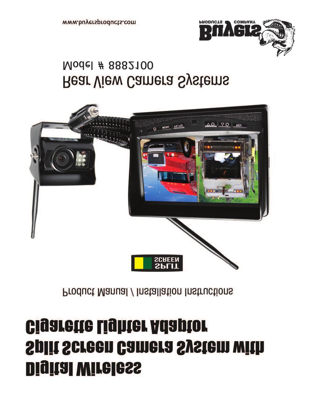
1 Split Screen Digital Wireless Monitor with Cigarette Lighter Adaptor 1 CCD Wireless Backup Camera with Power Cable 1 Extendable Suction Cup Mount
|
|
|
- Cameron Clarke
- 5 years ago
- Views:
Transcription
1

2 What s in the Box? 1 Split Screen Digital Wireless Monitor with Cigarette Lighter Adaptor 1 CCD Wireless Backup Camera with Power Cable 1 Extendable Suction Cup Mount for Monitor
3 Table of Contents Introduction...4 Safety Information Before Beginning Installation...8 Installation Guide...9 Pairing...10 System Operation...11 Operational Diagram...12 Installation Diagram...13 Monitor Dimensions...14 Monitor Specifications...15 Camera Dimensions Camera Specifications...17 Splitting...18 Positioning...19 Troubleshooting...20 Warranty...21 Disclaimer...22
4 Introduction Congratulations on purchasing a Rear View Backup Camera System! With this manual you will be able to properly install and operate the unit. The Backup Camera System is intended to be installed as a supplement aid to your standard rear view mirror that already exists in your vehicle. The Backup Camera System should not be used as a substitute for the standard rear view mirror or for any other mirror that exists in your vehicle. In some jurisdictions, it is unlawful for a person to drive a motor vehicle equipped with a TV viewer or screen located forward of the back of the driver s seat or in any location that is visible, directly or indirectly, to the driver while operating the vehicle. 4
5 Safety Information Please read the entire manual and follow the instructions and warnings carefully. Failure to do so can cause serious damage and/or injury, including loss of life. Be sure to obey all applicable local traffic and motor vehicle regulations as it pertains to this product. Improper installation will void manufacturer s warranty. USAGE The Rear View Camera System is designed to help the driver safely detect people and/or objects helping to avoid damage or injury. However, you the driver, must use it properly. Use of this system is not a substitute for safe, proper or legal driving. Never back up while looking at the monitor alone. You should always check behind and around the vehicle when backing up, in the same way as you would if the vehicle did not have the Rear View Camera System. If you back up while looking only at the monitor, you may cause damage or injury. Always back up slowly. The Rear View Camera System is not intended for use during exstensive back-up maneuvers or backing into cross traffic or pedestrian walkways. Please, always remember, the area displayed by the Rear View Camera System is limited. It does not display the entire panorama that is behind you. 5
6 Safety Information INSTALLA TION Electric shock or product malfunction may occur if this product is installed incorrectly. Use this product within the voltage range specified. Failure to do so can cause electronic shock or product malfunction. Take special care when cleaning the monitor. Make sure to firmly affix the product before use. If smoke or a burning smell is detected, disconnect the system immediately. Where the power cable may touch a metal case, cover the cable with a friction tape. A short circuit or disconnected wire may cause a fire. While installing the Rear View System be careful with the wire positioning in order to avoid wire damage. The Rear View System should only be used when the vehicle is in reverse. Do not watch movies or operate the monitor while driving; as it may cause an accident. Do not install the monitor where it may obstruct drivers view or obstruct an air bag device. Dropping the unit may cause possible mechanical failure. 6
7 Safety Information If you have questions about this product, contact: Buyers Products Company 9049 Tyler Blvd. Mentor, Ohio Phone (440) Fax IN NO EVENT SHALL SELLER OR MANUFACTURER BE LIABLE FOR ANY DIRECT OR CONSEQUENTIAL DAMAGES OF ANY NATURE, OR LOSSES OR EXPENSES RESULTING FROM ANY DEFECTIVE PRODUCT OR THE USE OF ANY PRODUCT. 7
8 Before Beginning Installation Before drilling please check that no cable or wiring is on the other side of the wall. Please clamp all wires securely to reduce the possibility of them being damaged while vehicle is in use. Keep all cables away from hot or moving parts and electrical noisy components. Step 1: Choose the monitor and camera locations. Step 2: Install all cables in vehicle, when necessary a 0.8 (20mm) hole should be drilled for passing camera cable through vehicles walls. Install split grommets where applicable. Step 3: Once all cables and wiring have been properly routed and the system has paired, perform a system function test by temporarily connecting the system. If the problem persists see troubleshooting (page 20). We recommend doing a benchmark test before installation to insure that all components are working properly. SYSTEM COMES PAIRED. But if there is no image on monitor, your system is NOT paired and needs to be paired. (see page 10) 8
9 Installation Guide Camera Connection: Locate the clearance lights wiring on your vehicle. You may need to remove the interior panel in order to locate. Connect the power cables for camera: Red wire to light's positive; Black wire to chassis ground. Monitor Connection: Firmly insert the lighter plug to cigarette lighter socket. Do not install the monitor where it may obstruct driver s view or obstruct and air bag device.... Cleaning If dirt, rain or snow attaches to the camera, the monitor may not clearly display objects. Do not use alcohol, benzene or thinner to clean the camera. This will cause discoloration. To clean the camera, wipe with a clean cloth dampened with mild cleaner diluted with water and then wipe with a dry cloth. 9
10 Pairing Pairing: 1. Use the "CAM" button to select the channel you want to pair to. 2. Press "MENU" to open the menu and press "MENU" again to initiate "pairing mode". Once "pairing mode" is active it will last for 50 seconds. 3. Press the pair button on the back of the camera within the 50 seconds and the camera image will appear on the monitor. The system is paired. NOTE: Please make sure the camera is receiving power when you pair. 10
11 System Operation System Operation: To turn on the monitor, press POWER ON button. To get to Main Menu, press MENU Use the arrow keys to navigate the menu and use the "MENU" button to confirm your selection. To go back, press the "REV" button. To adjust the volume, use the up and down arrows while viewing the camera Menu Options: Image - adjust the image properties (brightness,contrast,saturation) Rotate - rotate the image in all four directions Settings - adjust the grid-lines and the frequency 11


12 Operational Diagram CAMERA SELECTION DOWN ARROW MENU/ SELECTION BUTTON UP ARROW POWER ON / OFF BACK 12
13 Monitor Specification TFT LCD Digital Monitor Screen Size 7 Dot Resolution 800H x 3 (RGB) 480V Display Format 16:9 / 500:1 Display Brightness 400cd/m 2 Viewing Angle U:50 / D:60 / R:70 Video Input 2 channel Video Source 1Vp-p, 75Ω Power Supply DC 12V(+/- 10%) Power Consumption 5W Operating Temperature -30 C ~ +80 C Video System Auto NTSC/PAL Overall Dimensions 7 L x 5 H x 1 D Weight 400G Impact Rating 5G Dot Pitch 0.192H x V Sync System Internal Weight 520g 13 13
14 14 Camera Dimensions
15 Camera Specifications Camera 1/4 Sharp Color CCD Picture Elements 250,000 pixels Gamma Correction r=0.45 to 1.0 Image Sensor 480TV lines Lens 2.1mm View Angle 130 Sync System Internal Synchronization Infrared distance 50 Feet (9 Infrared) Usable Illumination 0 Lux (IR On) Power Source DC 12V (+/- 10%) S/N Ratio More than 48dB Electronic Iris 1/50, 160-1/100,000sec Video Output 1Vp.p 75ohm IR Switch Control ACDS Automatic Control Impact Rating 20G Vibration/100G Shock Operating Temperature -30 C C/RH 95% Max Storage Temperature -30 C C/RH 95% Max Waterproof Rating IP


16 Splitting Installing sun shield: Put shade cover on the display. Installing back cover: Put the monitor with shade cover in the back cover (only for embedded monitor) Splitting back cover: Hold monitor with 2 hands and detach with fingers, as indicated by arrows. (only for embedded monitor) Splitting sun shield: Take the monitor with the left hand and detach with right hand as indicated by the white arrow. (see below) 16
17 Positioning 17 17
18 Troubleshooting Monitor Displays Blue Screen & Displays No Signal Do a hard reset, unplug all cables and power cables leave out for 1 minute and then re-connect them. Check to ensure that the connection to the camera is tight. Verify camera is on correct camera input No Image On Screen Verify camera is connected to power/ground Audio on Camera Verify chosen camera has audio Verify volume setting The antenna booster is an extendable antenna that can be used in case of signal issues. Signal Issues The cable is attached just like the standard antenna by screwing on the connection- The antenna itself is attached magnetically. 18
19 Warranty One Year Warranty Buyers Products Company warrants this product against material defects for a period of one year from date of purchase. We reserve the right to repair or replace any such defective unit at our sole discretion. Buyers Products Company is not responsible for a defect in the system as a result of misuse, improper installation, damage or mishandling of the electronic components. Buyers Products Company is not responsible for consequential damages of any kind. This warranty is void if: defects in materials or workmanship or damages result from repairs or alterations which have been made or attempted by others or the unauthorized use of nonconforming parts; the damage is due to normal wear and tear, this damage is due to abuse, improper maintenance, neglect or accident; or the damage is due to use of the Buyers Products Company system after partial failure or use with improper accessories. Warranty Performance DURING THE ABOVE WARRANTY PERIOD, SHOULD YOUR BUYERS PRODUCTS COMPANY PRODUCT EXHIBIT A DEFECT IN MATERIAL OR WORKMANSHIP, SUCH DEFECT WILL BE REPAIRED WHEN THE COMPLETE BUYERS PRODUCTS COMPANY PRODUCT IS RETURNED, POSTAGE PREPAID AND INSURED, TO BUYERS PRODUCTS COMPANY OTHER THAN THE POSTAGE AND INSURANCE REQUIREMENT, NO CHARGE WILL BE MADE FOR REPAIRS COVERED BY THIS WARRANTY. Warranty Disclaimers NO WARRANTY, ORAL OR WRITTEN, EXPRESSED OR IMPLIED, OTHER THE ABOVE WARRANTY IS MADE WITH REGARD TO THIS BUYERS PRODUCTS COMPANY DISCLAIMS ANY IMPLIED WARRANTY OR MERCHANT-ABILITY OR FITNESS FOR A PARTICULAR USE OR PURPOSE AND ALL OTHER WARRANTIES IN NO EVENT SHALL BUYERS PRODUCTS COMPANY LIABLE FOR ANY INCI- DENTAL, SPECIAL, CONSEQUENTIAL, OR PUNITIVE DAMAGES OR FOR ANY COSTS, ATTORNEY FEES, EXPENSES, LOSSES OR DELAYS ALLEGED TO BE AS A CONSEQUENCE OF ANY DAMAGE TO, FAILURE OF, OR DEFECT IN ANY PROD- UCT INCLUDING, BUT NOT LIMITED TO, ANY CLAIMS FOR LOSS OF PROFITS
20 20 Disclaimer Buyers Products Company and/or its affiliates does not guarantee or promise that the user of our systems will not be in/part of an accident or otherwise not collide with an object and/or person. Our systems are not a substitute for careful and cautious driving or for the consistent adherence to all applicable traffic laws and motor vehicle safety regulations. The Buyers Products Company products are not a substitute for rearview mirrors or for any other motor vehicle equipment mandated by law. Our camera systems have a limited field of vision and do not provide a comprehensive view of the rear or side area of the vehicle. Always make sure to look around your vehicle and use your mirrors to confirm rearward clearance and that your vehicle can maneuver safely. Buyers Products Company and/or its affiliates shall have no responsibility or liability for damage and/or injury resulting from accidents occurring with vehicles having some of Buyers Products Company products installed, and Buyers Products Company and/or its affiliates, the manufacturer, distributor and seller shall not be liable for any injury, loss or damage, incidental or consequential, arising out of the use or intended use of the product. In no event shall Buyers Products Company and/or its affiliates have any liability for any losses (whether direct or indirect, in contract, tort or otherwise) incurred in connection with the systems, including but not limited to damaged property, personal injury and/or loss of life. Neither shall Buyers Products Company and/or its affiliates have any responsibility for any decision, action or inaction taken by any person in reliance on Buyers Products Company systems, or for any delays, inaccuracies and/or errors in connection with our systems functions.
21 9049 Tyler Blvd. Mentor, Ohio Phone (440) Fax
Instruction Manual. 2.4G Digital Wireless Four Channel Transmitter System RVS-554W. Reverse With Confidence 1
 Instruction Manual 2.4G Digital Wireless Four Channel Transmitter System RVS-554W 1 NOTE! Please read all of the installation instructions carefully before installing the product. Improper installation
Instruction Manual. 7" Wireless Camera System with Wired Side Camera Inputs RVS-355W. Reverse With Confidence 1
 Instruction Manual 7" Wireless Camera System with Wired Side Camera Inputs RVS-355W Reverse With Confidence 1 RVS-355W.indd 1 10/2/2017 3:33:32 PM TABLE OF CONTENTS Introduction..............................
Phone (440) Fax Wireless Rear Observation System With Night Vision Camera
 Fax Wireless Rear Observation System With Night Vision Camera") www.buyersproducts.com Phone (440) 974-8888 Fax 800-841-8003 8883200 Wireless Rear Observation System With Night Vision Camera 1 Table of Contents What's in the Box?...3 Introduction...4 Safety Information...5-6
www.buyersproducts.com Phone (440) 974-8888 Fax 800-841-8003 8883200 Wireless Rear Observation System With Night Vision Camera 1 Table of Contents What's in the Box?...3 Introduction...4 Safety Information...5-6
What s in the Box? RVS SYSTEMS
 TM 1 What s in the Box? 1 Color CCD Infra-red Weather Proof Camera 1 7" LED Color Monitor w/universal Mount/Stand & Wire 1 3 Channel Multiplexer Control Unit 1 66 Camera Cable 1 Remote Control 1 Power
Safety Information. Camera System. If you back up while looking only at the monitor, you may cause damage or injury. Always back up slowly.
 Table of Contents Introduction...3 Safety Information...4-6 Before Beginning Installation...7 Installation Guide...8 Wiring Camera & Monitor...9-10 Replacement Installation Diagram...11 Clip-On Installation
Instruction Manual. Wireless Transmitters (Digital) RVS-550W. Reverse With Confidence 1
 RVS-550W. Reverse With Confidence 1") Instruction Manual Wireless Transmitters (Digital) RVS-550W Reverse With Confidence 1 TABLE OF CONTENTS In The Box 1 x Transmitter 1 x Receiver TABLE OF CONTENTS Table of Contents................................
Instruction Manual Wireless Transmitters (Digital) RVS-550W Reverse With Confidence 1 TABLE OF CONTENTS In The Box 1 x Transmitter 1 x Receiver TABLE OF CONTENTS Table of Contents................................
Instruction Manual. OEM G-Series Backup Camera System with Frameless Mirror Monitor RVS Reverse With Confidence 1
 Instruction Manual OEM G-Series Backup Camera System with Frameless Mirror Monitor RVS-218640 Reverse With Confidence 1 TABLE OF CONTENTS Introduction.............................. 03 Safety Information..............................
Instruction Manual. Wireless Safety Camera System for Forklifts with 5" Dual Screen Display RVS Reverse With Confidence 1
 Instruction Manual Wireless Safety Camera System for Forklifts with 5" Dual Screen Display RVS-655155 Reverse With Confidence 1 TABLE OF CONTENTS Introduction.............................. 03 Safety Information..............................
what s in the Box? Camera transmitter with power cable 3M sticker 2 RVS SYSTEMS
 TM 1 what s in the Box? Camera transmitter with power cable 3M sticker 2 RVS SYSTEMS table of Contents introduction...4 features...5 Specifications...6-7 installation...8-9 Operations...10-15 Disclaimer...16
Digital Tiny Traveler Wireless Baby Monitor for Your Car
 Digital Tiny Traveler Wireless Baby Monitor for Your Car BT53901F-1 USER MANUAL ML-53901F_V1 IF YOU ARE EXPERIENCING ANY ISSUES WITH THE PRODUCT DURING OPERATION, DO NOT RETURN THE PRODUCT TO THE STORE.
Owner s Manual. Backup Monitor System. LCD Monitor & CCD Color Camera
 Backup Monitor System LCD Monitor & CCD Color Camera Backup Monitor System Copyright 2003 TMI Products, Inc. All Rights Reserved Corona, CA U.S.A. 060300 Owner s Manual 1493 Bentley Drive Corona, CA 92879
AWT150C/AWT150CS/ AWT151C CCD Camera
 AWT150C/AWT150CS/ AWT151C CCD Camera ISSUED OCTOBER 2018 WARNING Failure to follow all instructions and safety precautions in this manual, in the vehicle and body manufacturers' manuals and on the safety
Do not install and/or operate this safety product unless you have read and understand the safety information contained in this manual.
 Installation and Operation Instructions CD3766 Directional LED Available in various color combinations, the CD3766 Directional LED is a surface mount, dual color warning light that is ideal for a wide
Be sure to check the camera is properly functioning, is properly positioned and securely mounted, every time you operate your vehicle.
 Please read all of the installation instructions carefully before installing the product. Improper installation will void manufacturer s warranty. The installation instructions do not apply to all types
Indoor/Outdoor Security System with Quad Monitor User s Manual
 Indoor/Outdoor Security System with Quad Monitor User s Manual 4919539 Important! Please read this booklet carefully before installing or using these units. WARNING - These units should ONLY be opened
7 LCD Color Monitor 8 LCD Color Monitor OWNER S MANUAL
 7 LCD Color Monitor 8 LCD Color Monitor OWNER S MANUAL INTRODUCTION OHM720, OHM820 The Clarion OHM720/OHM820 is a full-featured 7 /8 LCD Color Monitor that can be used as a stand-alone monitor, or can
Garmin GC 10 Marine Camera Instructions
 Garmin GC 10 Marine Camera Instructions FCC Compliance This device complies with part 15 of the FCC Rules. Operation is subject to the following two conditions: (1) this device may not cause harmful interference,
SM-816DT User s Manual. 2.4GHz Digital Wireless Outdoor/Indoor Camera with Night Vision and Audio
 SM-816DT User s Manual 2.4GHz Digital Wireless Outdoor/Indoor Camera with Night Vision and Audio Copyright 2012 This manual is furnished under license and may be used or copied only in accordance with
JS007WQK HEAVY DUTY WIRELESS REVERSING KIT 7 LCD DIGITAL QUAD RECORDING MONITOR with WATERPROOF CCD CAMERA
 JS007WQK HEAVY DUTY WIRELESS REVERSING KIT 7 LCD DIGITAL QUAD RECORDING MONITOR with WATERPROOF CCD CAMERA The JS007WQK is loaded with userfriendly features and is ideal for use in heavy duty vehicles.
TECHNICAL SUPPORT , or FD151CV-LP Installation and Operation Manual 15.1 Low Profile LCD
 TECHNICAL SUPPORT 678-867-6717, or www.flightdisplay.com FD151CV-LP Installation and Operation Manual 15.1 Low Profile LCD FD151CV-LP 15.1" Low Profile LCD 2006 Flight Display Systems. All Rights Reserved.
Operation Manual VMS 3.0 Video System
 Operation Manual VMS 3.0 Video System for the AlterG Anti-Gravity Treadmill 1 This manual covers operation procedures for the following AlterG products: AlterG Video System model VMS 3.0 NOTE: The following
DSP x1 Color Screen Splitter Instruction Manual
 DSP-1200 2x1 Color Screen Splitter Instruction Manual Thank you for purchasing one of our products. Please read this manual before using this product. When using this product, always follow the instructions
3.5 TFT LCD CCTV Service Viewer with Wristband
 User Manual 3.5 TFT LCD CCTV Service Viewer with Wristband LCD35SV It can proved the 12V DC power to camera for easy trouble shoot. LCD35SV is a type of product that summarizes views of first-line safety
VMA573 and VMA or 7 Wide Screen Color LCD Monitor. Owner s Manual. Installation Guide
 VMA573 and VMA773 5.6 or 7 Wide Screen Color LCD Monitor Owner s Manual Installation Guide 7 headrest / stand alone wide monitor 5.6 headrest / stand alone wide monitor 2 WARINING! The Clarion VMA 573
SV-LCD50. Installation and User Guide. Thin-Film Transistor (TFT) Liquid Crystal Display (LCD) Color Rear Vision Monitor. Version 1.
 Liquid Crystal Display (LCD) Color Rear Vision Monitor. Version 1.") SV-LCD50 Installation and User Guide Thin-Film Transistor (TFT) Liquid Crystal Display (LCD) Color Rear Vision Monitor Version 1.00 August 2004 SV-LCD50 Installation and User Guide TFT LCD Color Rear Vision
SV-LCD50 Installation and User Guide Thin-Film Transistor (TFT) Liquid Crystal Display (LCD) Color Rear Vision Monitor Version 1.00 August 2004 SV-LCD50 Installation and User Guide TFT LCD Color Rear Vision
CM-S38901SV TVL IR Long Range camera
 5 40 TVL IR Long Range camera User s Guide CM-S38901SV SAFETY PRECAUTIONS WARNING 1. Be sure to use only the standard adapter that is specified in the specification sheet. Using any other adapter could
FD171CV-C-4. Installation and Operation Manual. 17 HDSDI Special Mission Quad Monitor. Revision Date: 01/11/2017 Page 1 of 14.
 Page 1 of 14 Installation and Operation Manual FD171CV-C-4 17 HDSDI Special Mission Quad Monitor Page 2 of 14 Table of Contents General Information...3 Front View...3 Additional Information...3 Specifications...4
Model: LCD4WM 3.5 Window Mounted LCD Monitor User Manual Features
 Model: LCD4WM 3.5 Window Mounted LCD Monitor User Manual Features 3.5 High Resolution TFT LCD Monitor Low Profile, Slim Design Fully Adjustable reversing guidelines Built in Speaker Two video inputs Fully
HDMI Extender over UTP Cable
 User Manual HDMI Extender over UTP Cable VHDE-300 Tx Rx Features.. Extends HDMI 1080p AV and IR Signals Transmission distance up to 60m/200ft via CAT6 cable or higher grade cable 5V DC, 1A Important Safety
Table of Contents. Introduction Pin Description Absolute Maximum Rating Electrical Specifications... 4
 Table of Contents Introduction... 1 Pin Description... 2 Absolute Maximum Rating... 3 Electrical Specifications... 4 Mechanical Specifications... 5 Thermal Specifications... 6 Over Temperature Protection...
CM-S23349SV. Vari-Focal IR Bullet Camera
 Vari-Focal IR Bullet Camera User s Guide CM-S23349SV SAFETY PRECAUTIONS WARNING 1. Be sure to use only the standard adapter that is specified in the specification sheet. Using any other adapter could cause
Outdoor IR Audio Camera
 Outdoor IR Audio Camera User s Guide CM-S22326BW-AD SAFETY PRECAUTIONS WARNING 1. Be sure to use only the standard adapter that is specified in the specification sheet. Using any other adapter could cause
INSTALLATION MANUAL. ST-CVTSD520-WSD-W Smoke Detector Covert Camera. v1.2 8/11/11 1
 INSTALLATION MANUAL ST-CVTSD520-WSD-W Smoke Detector Covert Camera v1.2 8/11/11 1 PACKAGE CONTENTS This package contains: One ST-CVTSD520-WSD-W smoke detector covert camera One installation manual Mounting
BRIGHTLINK HD Video Wall Controller BRIGHTLINKAV.COM
 BRIGHTLINK HD Video Wall Controller MODEL: BL-VW22 Operating Instructions BRIGHTLINKAV.COM Dear Customer Thank you for purchasing this product. For optimum performance and safety, please read these instructions
Quick Installation Guide. Indoor / Outdoor Antenna, Antenna Cable & Surge Arrestor
 Quick Installation Guide Indoor / Outdoor Antenna, Antenna Cable & Surge Arrestor Table of Contents... 1 1. Outdoor Antenna Installation... 1 2. How to install the surge arrestor... 4 3. Weatherproof tape
User s Guide. 5.8GHz Wireless A/V Signal Sender
 1500332 User s Guide 5.8GHz Wireless A/V Signal Sender Thank you for purchasing your A/V Signal Sender from RadioShack. Please read this user s guide before installing, setting up, and using your new sender.
Owner s Manual. VL9000 Series HEADREST MONITOR SYSTEM
 VL9000 Series HEADREST MONITOR SYSTEM Copyright 2003 TMI Products, Inc. All Rights Reserved Corona, CA U.S.A. 060300 Owner s Manual 1493 Bentley Drive Corona, CA 92879 909-272-1996 800-624-7960 Fax 909-272-1584
DUOVIEW FRONT AND REAR CAMERA SYSTEM
 DUOVIEW FRONT AND REAR CAMERA SYSTEM TABLE OF CONTENTS 1. Introduction...1 2. Package Contents...2 3. Product Specifications...3 4. Safety Information...5 5. Operation...6 6. Settings...9 7. Viewing Files...12
Operating Instructions
 Operating Instructions LCDRV700 Digital LCD Color Monitor Please read this manual thoroughly before operating the unit, and keep it for future reference. V1.0 Contents 1. Precautions 2. Features 1 3 3.
User Manual Part Number: DMOV 7M C2
 TROUBLESHOOTING Problem No picture, no sound No picture No sound Dark picture No color Upside down or lateral inverted picture Event Triggers not activating (i.e. No picture during triggered event) Remote
The specially designed stand (Included) made possible to use it indoor as well.
 made possible to use it indoor as well.") Instruction manual Terrestrial Digital TV Antenna Model: UDF-60 Indoor / Outdoor Thin design UHF Antenna Thank you for purchasing Nippon Antenna product. Please read this manual carefully before using
Instruction manual Terrestrial Digital TV Antenna Model: UDF-60 Indoor / Outdoor Thin design UHF Antenna Thank you for purchasing Nippon Antenna product. Please read this manual carefully before using
Indoor/Outdoor Analog Wired Camera Model P-520 USER'S MANUAL
 Indoor/Outdoor Analog Wired Camera Model P-520 USER'S MANUAL WELCOME Welcome Thank you for choosing First Alert for your security needs! For more than half a century, First Alert has made the home-safety
FD70CV-M-C-9. Installation and Operation Manual. 7 NVG Compatible LCD. Revision Date: 06/16/2017 Page 1 of 12. Rev: A
 Page 1 of 12 Installation and Operation Manual FD70CV-M-C-9 7 NVG Compatible LCD Page 2 of 12 Specifications Display FD70CV-M-C-9 Panel Technology Diagonal Screen Size Native Resolution Pixel Pitch TN,
User Guide. HDMI Active Cable Extender. DVI-7370c
 User Guide HDMI Active Cable Extender DVI-7370c TABLE OF CONTENTS SECTION PAGE PRODUCT SAFETY...1 PRODUCT LIABILITY STATEMENT........................ 1 1.0 INTRODUCTION...2 2.0 SPECIFICATIONS...3 3.0 PACKAGE
PRO-ScalerHD2V HDMI to VGA & Audio Scaler Converter. User s Guide. Made in Taiwan
 PRO-ScalerHD2V HDMI to VGA & Audio Scaler Converter User s Guide Made in Taiwan Congratulations for owning a gofanco product. Our products aim to meet all your connectivity needs wherever you go. Have
900-Lumen Portable LED Projector Part #: User manual
 900-Lumen Portable LED Projector Part #: 21797 User manual 900-Lumen LED Projector Manual Page 2 of 14 900-Lumen LED Projector Manual Page 3 of 14! SAFETY WARNINGS AND CAUTIONS WARNING: To reduce the risk
Dakota Micro, Inc. Users Manual. Digital Wireless Two Camera Monitoring System Part Number: DMOV DW7MC2
 Users Manual Digital Wireless Two Camera Monitoring System Part Number: DMOV DW7MC2 Table of Contents I. Included Wireless Kit Components 2 II. Optional Wireless Kit Components 2 III. Standard Features
Website: Tel: ADDRESS: 6475 Las Positas Rd. Livermore, CA Item No. E5B/E5S Installation Guide
 Website: www.flexispot.com Tel: -855-4-808 ADDRESS: 6475 Las Positas Rd. Livermore, CA 9455 Item No. E5B/E5S Installation Guide Specifications Step Column 3 Max. Weight Capacity 0 Ibs (00 kg) Speed 38mm/s
INSTRUCTIONAL MANUAL FOR LCD ZOOM MICROSCOPE
 INSTRUCTIONAL MANUAL FOR LCD ZOOM MICROSCOPE ? 8 LCD Screen? 10.4 LCD Screen LCD Zoom Microscope Instruction Manual Please read the Instruction Manual carefully before installation and keep it for future
Operating Instructions
 Operating Instructions Digital LCD Color Monitor Please read this manual thoroughly before operating the unit, and keep it for future reference. V1.0 Contents 1. Precautions 2. Features 3. Technical Specifications
SC-C1M SiriusConnect TM Vehicle Tuner
 SC-C1M SiriusConnect TM Vehicle Tuner For Special Market Applications Installation Guide Congratulations on the Purchase of your new SIRIUS SC-C1 SiriusConnect TM Vehicle Tuner. The SC-C1M is packaged
OWNER S MANUAL MOTORIZED 7 WIDE TFT LCD COLOR MONITOR CNT-701
 OWNER S MANUAL PW MOTORIZED 7 WIDE TFT LCD COLOR MONITOR CNT-701 ANY CHANGES OR MODIFICATIONS IN CONSTRUCTION OF THIS UNIT DEVICE WHICH IS NOT APPROVED BY THE PARTY RESPONSIBLE FOR COMPLIACE COULD VOID
User Guide. Single-Link DVI Active Cable Extender. DVI-7171c
 User Guide Single-Link DVI Active Cable Extender DVI-7171c TABLE OF CONTENTS SECTION PAGE PRODUCT SAFETY...1 PRODUCT LIABILITY...1 1.0 INTRODUCTION...2 2.0 SPECIFICATIONS...3 3.0 PACKAGE CONTENTS...4 4.0
INSTALLATION MANUAL. ST-CVTMD420-WPIR-W Covert Motion Detection Color Camera. v1.3 8/11/11 1
 INSTALLATION MANUAL ST-CVTMD420-WPIR-W Covert Motion Detection Color Camera v1.3 8/11/11 1 PACKAGE CONTENTS This package contains: One ST-CVTMD420-WPIR-W covert motion detection camera One installation
Black & White Wireless Video Surveillance System
 MODEL: 2BWIR Black & White Wireless Video Surveillance System INSTALLATION MANUAL V1.0 N517 Camera Monitor - Compact 2.4 GHz Mini Black & White Camera - 5.5 High Resolution CRT - Sturdy Design with Metal
Table of contents. Opening the Overhead Monitor... 4 Precautions Care And Maintenance... 5 Operating OHM102/153 Monitor...
 Warning! The Clarion OHM102/OHM153 overhead monitor systems are designed for strictly for rear seat entertainment. Viewing the monitor while operating a motor vehicle can result in serious injury and/or
FD102CV. Installation and Operation Manual Widescreen LCD. Revision Date: 02/01/2012 Page 1 of 16. Rev: K. Document Number: MAN FD102CV
 Page 1 of 16 Installation and Operation Manual FD102CV 10.2 Widescreen LCD Page 2 of 16 FD102CV 10.2 Widescreen LCD 2006 Flight Display Systems. Flight Display Systems 6435 Shiloh Road Alpharetta, GA 30005
TVAC20000 User manual
 TVAC20000 User manual Version 01/2010 Original English user manual. Keep for future use. 10 Introduction Dear Customer, Thank you for purchasing this product. This product meets the requirements of the
HDTV Supply Inc. reserves the right to make changes in the hardware, packaging and any accompanying documentation without prior written
 HDMI Matrix (Router Type) Model No. HDTVMX0404313 HDTV Supply, Inc Features Easy to use: install in seconds, no need for setting. Allows up to four HDMI audio/video devices to be independently switched
FD104CV. Installation and Operation Manual 10.4 LCD MAN FD104CV. TECHNICAL SUPPORT , or Document Number: Rev:
 Page 1 of 16 FD104CV Installation and Operation Manual 10.4 LCD TCHNICAL SUPPORT 678-867-6717, or www.flightdisplay.com Page 2 of 16 FD104CV 10.4 LCD 2006 Flight Display Systems. All Rights Reserved. Flight
PLL1920M LED LCD Monitor
 PLL1920M LED LCD Monitor USER'S GUIDE www.planar.com Content Operation Instructions...1 Safety Precautions...2 First Setup...3 Front View of the Product...4 Rear View of the Product...5 Installation...6
VMA ACTIVE MATRIX TFT COLOR LCD MONITOR OWNER S MANUAL INSTALLATION GUIDE
 VMA6491 6.4 ACTIVE MATRIX TFT COLOR LCD MONITOR OWNER S MANUAL INSTALLATION GUIDE OWNER S MANUAL WARNING! THE CLARION VMA6491 LCD MONITOR IS DESIGNED FOR REAR SEAT PASSENGER VIEWING ONLY. THIS PRODUCT
Low Profile Digital HDTV Over-the-Air Antenna CONTENTS
 Low Profile Digital HDTV Over-the-Air Antenna w/built-in KING SureLock Digital TV Signal Meter Owner s Manual Roof Thickness: 1 to 4-1/2 Roof Thickness: 4-1/2 to 8 (when installed with KING extension #21850)
User Manual. AtlonA. 7 PRO HD Monitor with HDMI, VGA and Component Inputs (up to 1080p or 1920x1200) AT-DIS7-PROHD
 AT-DIS7-PROHD") User Manual AtlonA 7 PRO HD Monitor with HDMI, VGA and Component Inputs (up to 1080p or 1920x1200) AT-DIS7-PROHD TABLE OF CONTENTS 1. Introduction... 3 2. Appplications... 3 3. Package Contents... 3 4.
User Manual AtlonA 7 PRO HD Monitor with HDMI, VGA and Component Inputs (up to 1080p or 1920x1200) AT-DIS7-PROHD TABLE OF CONTENTS 1. Introduction... 3 2. Appplications... 3 3. Package Contents... 3 4.
Cablesson HDelity 7.1ch Audio Extractor & Mixer. User Manual
 Cablesson HDelity 7.1ch Audio Extractor & Mixer User Manual All rights reserved - CABLESSON All rights reserved - CABLESSON ! SAFETY AND NOTICE The Cablesson HDelity HDMI 7.1ch Audio Extractor and Mixer
Low Profile Digital HDTV Over-the-Air Antenna CONTENTS
 Low Profile Digital HDTV Over-the-Air Antenna Owner s Manual Roof Thickness: 1 to 4-1/2 Roof Thickness: 4-1/2 to 8 (when installed with KING extension #21850) OA8400 White OA8401 Black CONTENTS OPERATION
User Instructions. 16 SCB Sync Station.
 User Instructions 16 SCB Sync Station Contents Overview... 1 Specifications... 1 Compliance and approvals... 2 Safety instructions... 3 Set up... 4 How to charge multiple devices... 4 How to synchronize
EZ-LIGHT K30L Series With Independent Push Button Contact
 EZ-LIGHT K0L Series With Independent Push Button Contact Datasheet Compact with One, Two, or Three s and a Momentary Push Button Output Rugged, cost-effective and easy-to-install multicolor indicator light
5 Port DVI Splitter VIDEO WALLS VIDEO PROCESSORS VIDEO MATRIX SWITCHES EXTENDERS SPLITTERS WIRELESS CABLES & ACCESSORIES
 AV Connectivity, Distribution And Beyond... VIDEO WALLS VIDEO PROCESSORS VIDEO MATRIX SWITCHES EXTENDERS SPLITTERS WIRELESS CABLES & ACCESSORIES 5 Port DVI Splitter Model #: SPLIT-DVI-5 2013 Avenview Inc.
Operating Instructions
 Model No.: TESTER-H01 Operating Instructions Thanks for purchasing our product. Please be sure to read this instruction manual carefully before using our product. Contents HDMI Signal Generator...1 Product
PRO-ScalerV2HD VGA to HDMI & Audio Scaler Converter. User s Guide. Made in Taiwan
 VGA to HDMI & Audio Scaler Converter User s Guide Made in Taiwan Congratulations for owning a gofanco product. Our products aim to meet all your connectivity needs wherever you go. Have fun with our products!
VOH681/VOH681P. ion Manual
 VOH681/VOH681P Operat ation ion Manual Important Notice It is unlawful in most jurisdictions for a person to drive a motor vehicle which is equipped with a television viewer or screen that is located in
VectorVGA Tempest User Manual
 VectorVGA Tempest User Manual 2 Notice Regarding This Product WARNING! To install this product you should: Be familiar with safe handling procedures for electronic components. Be able to use hand tools
Advanced security made easy PRO-555. Day/Night CCD Security Camera. Operating Instructions SW331-PR5 SR331-PR
 Advanced security made easy PRO-555 Day/Night CCD Security Camera Operating Instructions SW331-PR5 www.swannsecurity.com SR331-PR5-60010-260809 1 Before You Begin FCC Verification: NOTE: This equipment
Instruction Guide. The TV Jockey Computer Monitor TV Tuner with Remote COMP2VGATVGB. The Professionals Source For Hard-to-Find Computer Parts
 VIDEO ADAPTER The TV Jockey Computer Monitor TV Tuner with Remote COMP2VGATVGB Instruction Guide * Actual product may vary from photo The Professionals Source For Hard-to-Find Computer Parts FCC COMPLIANCE
VHF + UHF Amplified HDTV Antenna Model OA8000 & OA8001 Installation Instructions Reception Frequencies
 VHF + UHF Amplified HDTV Antenna Model OA8000 & OA8001 Installation Instructions Reception Frequencies VHF: 54-216 MHz UHF: 470-698 MHz FM: 87.9-107.9 MHz Voltage Input: AC110-120V / AC220-240V Working:
FD104CV. Installation and Operation Manual 10.4 LCD. Revision Date: 08/01/2017 Page 1 of 14. Rev: G. Document Number: MAN FD104CV
 Page 1 of 14 Installation and Operation Manual FD104CV 10.4 LCD Page 2 of 14 Table of Contents eneral Information... 3 Front View... 3 Additional Information... 3 Specifications... 4 Installation Instructions...
USERS GUIDE MCX-HTS. HDMI to 3G SDI Converter. Manual Number:
 USERS GUIDE MCX-HTS HDMI to 3G SDI Converter i Manual Number: 151226 SAFETY INSTRUCTIONS Please review the following safety precautions. If this is the first time using this model, then read this manual
PLL2210MW LED Monitor
 PLL2210MW LED Monitor USER'S GUIDE www.planar.com Content Operation Instructions...1 Safety Precautions...2 First Setup...3 Front View of the Product...4 Rear View of the Product...5 Quick Installation...6
Kramer Electronics, Ltd. USER MANUAL. Model: VM Video Component Distributor
 Kramer Electronics, Ltd. USER MANUAL Model: VM-1045 Video Component Distributor Contents Contents 1 Introduction 1 2 Getting Started 1 2.1 Quick Start 1 3 Overview 3 4 Your VM-1045 Video Component Distributor
OWNER'S MANUAL SIGNAL COMMANDER
 OWNER'S MANUAL SIGNAL COMMANDER THIS MANUAL CONTAINS INSTRUCTIONS FOR: LPDA 100 - INSTALLATION - OPERATION - TROUBLESHOOTING - EXPLODED PARTS DIAGRAM - WARRANTY AntennaTek, Inc. 425 S. Bowen, # 4 Longmont,
AOM FLAT PANEL COLOR OBSERVATION MONITOR OWNER S MANUAL
 R AOM681 6.8 FLAT PANEL COLOR OBSERVATION MONITOR OWNER S MANUAL AOM681 Features:? 6.8 High Performance Color LCD? Water Resistant Design? Built-in Audio Speaker with Volume Control and 12V Trigger? 2
HDMI Extender Transmission more than 3800M
 HDMI Extender Transmission more than 3800M Operating Instructions Dear Customer Thank you for purchasing this product. For optimum performance and safety, please read these instructions carefully before
JACK Digital HDTV Over-the-Air Antenna
 JACK Digital HDTV Over-the-Air Antenna w/built-in SureLock Digital TV Signal Meter TM OA8200-White OA8201-Black SPECIFICATIONS Dimensions: 11.25 H x 16 W x 12.5 L Powered Amplifier +12 volt / 100 ma working
SP x6 12G/6G/3G/HD/SD-SDI Distribution Amplifier with Reclocking. User Manual. rev: Made in Taiwan
 SP-3026 1x6 12G/6G/3G/HD/SD-SDI Distribution Amplifier with Reclocking User Manual rev: 160815 Made in Taiwan Safety and Notice The SP-3026 1x6 12G/6G/3G/HD/SD-SDI Distribution Amplifier with Reclocking
HDMI Converter. Operating Instructions(P/N of this Instructions is INSYH0101)
") HDMI Converter Model No. YH0101 Operating Instructions(P/N of this Instructions is INSYH0101) Dear customer Thank you for purchasing this product. For optimum performance and safety, please read these
HDMI Converter Model No. YH0101 Operating Instructions(P/N of this Instructions is INSYH0101) Dear customer Thank you for purchasing this product. For optimum performance and safety, please read these
User Manual. 1x8 S-Video Distribution Amplifier With Stereo Audio AT-SAV18
 User Manual 1x8 S-Video Distribution Amplifier With Stereo Audio AT-SAV18 www.atlona.com TABLE OF CONTENTS 1. Introduction... 2 2. Features... 2 3. Package Contents... 2 4. Specification... 2 5. Panel
APSPB PUSH BUTTON ZERO Installation Manual
 APSPB PUSH BUTTON ZERO Installation Manual CARDINAL SCALE MFG. CO. 8527-0579-0M Rev A 203 E. Daugherty, Webb City, MO 64870 USA Printed in USA 12/14 Ph: 417-673-4631 Fax: 417-673-2153 www.detectoscale.com
User Manual rev: Made in Taiwan
 CV-500S HDMI to Component/CVBS & Audio Scaler Converter User Manual rev: 131218 Made in Taiwan The CV-500S HDMI to Component/CVBS & Audio Scaler Converter has been tested for conformance to safety regulations
Operating Instructions
 Model No.: MS0801-E02 Operating Instructions Thanks for purchasing our product. Please be sure to read this instruction manual carefully before using our product. Introduction MS0801-E02 supports to switch
Installation Instructions Wireless Camera/Monitor System
 Installation Instructions Wireless Camera/Monitor System Introduction: The Gemineye wireless camera system features 2.4GHZ digital signal transmission and offers quality and functionality equal to wired
JACK Digital HDTV Over-the-Air Antenna w/built-in SureLock Digital TV Signal Meter
 JACK Digital HDTV Over-the-Air Antenna w/built-in SureLock Digital TV Signal Meter OA8200 - White OA8201 - Black SPECIFICATIONS Dimensions: 11.25 H x 16 W x 12.5 L Powered Amplifier: +12 Volt / 100 ma
PL2410W LCD Monitor USER'S GUIDE.
 PL2410W LCD Monitor USER'S GUIDE www.planar.com Content Operation Instructions...1 Safety Precautions...2 First Setup...3 Front View of the Product...4 Rear View of the Product...5 Quick Installation...6
USER MANUAL Table of Contents
 USER MANUAL Table of Contents Safety Information. 3 Specifications.. 4 Main Power Connection.. 5 DMX-512 Connection...... 5 Main Control Menu... 6 Fixture Addressing... 6 Manual Mode...7 Save Scene...7
VK-P10SE WARRANTY REGISTRATION FORM
 VK-P10SE WARRANTY REGISTRATION FORM Unit Serial Number: Customer Name: Address: Date of Purchase: Purchased From: Dealer Name: Address: IMPORTANT NOTE: In order to receive the full five-year product warranty,
Linear Array with Intensity Adjustment
 Datasheet High-Power Lighting with Intensity Adjustment for use with Vision Systems For complete technical information about this product, including dimensions, accessories, and specifications, see www.bannerengineering.com/lineararraylights.
17 19 PROFESSIONAL LCD COLOUR MONITOR ART
 17 19 PROFESSIONAL LCD COLOUR MONITOR ART. 41657-41659 Via Don Arrigoni, 5 24020 Rovetta S. Lorenzo (Bergamo) http://www.comelit.eu e-mail:export.department@comelit.it WARNING: TO REDUCE THE RISK OF FIRE
Low Voltage Multifunctional LED Controller / DMX Decoder. Specification
 Low Voltage Multifunctional LED Controller / DMX Decoder Specification High Power DMX Decoder & Driver Meets DMX 512/1990 Protocol LT-300 can drive up to 8A current on each channel Capable of driving many
Operating Instructions
 Model No.: SPL1T801 Operating Instructions Thanks for purchasing our product. Please be sure to read this instruction manual carefully before using our product. Introduction Wyrestorm s SPL1T801 is a
User Manual TLS HDMI Switch 4/1 MHL
 875222 User Manual TLS HDMI Switch 4/1 MHL HDMI IN IR SW 4 3 2 1 OUT SBL/SBR SL/SR CEN/SUB FL/FR DIG AUDIO SPDIF DC 5V HDMI OUT 1 2 HDMI IN 3 MLH 4 8 875222 HDMI Switch 4/1 MHL Thank you for purchasing