CMS MANUAL DIGITAL VIDEO RECORDER CMS. Operation Manual 3CTC-016-5EN8M. For the safe use of the product, please make sure to read Safety Precautions.
|
|
|
- Lynn McGee
- 5 years ago
- Views:
Transcription
1 DIGITAL VIDEO RECORDER CMS Operation Manual 3CTC-016-5EN8M For the safe use of the product, please make sure to read Safety Precautions. 1
2 Copyrights All the contents of this manual are protected under the copyrights law. The whole manual or any portion of it cannot be reproduced or distributed without the prior consent of the copyright owner. Also, its transmission and distribution via online media are prohibited. For the performance improvement and correction of technical or printing errors, this manual is subject to change without prior notice. The symbol, logo, signature and trademark are all the official trademarks, and their ownership goes to the copyrighter. 2
3 Useful Information This manual is designed for customers who have purchase the CMS (Central Monitoring System). Please read through this manual. This manual consists of six chapters. The chapter 1 contains the CMS user environments, and how to install the Key Lock and programs. The chapter 2 includes the contents on how to execute the program. The chapter 3 deals with initial setting after CMS execution. The chapter 4 describes the server connection and camera interface. The chapter 5 explains the functions used in the monitoring status. The chapter 6 has the search method and functions description. And the chapter 7 holds the contents on how to set each server. CMS can access various servers through network, and receive the image from different servers to try monitoring, backup or search. In case of using two monitors or more, users can conduct different screens and processes for each monitor. (Ex, 1 monitor monitoring / 2 monitor search / 3 monitor setting) It can support monitors as many as VGA-card supports. Even if DVRs are different models from each other, users can have an access to them, as long as they are produced from the same manufacturer. Users can view the monitoring & search screens in 1000 fold magnification. Moreover, users can handle each channel at the same time doing other jobs. (Ex: 1 channel monitoring / 2 channel search) It is all right to use the CMS program and DVR Client / DVR BackupViewer at the same time. However, do not use it with commercial programs other than a DVR program at the same time. It may become a cause for system degradation. 3
4 Table of Contents 1. I n s t a l l a t i o n 1. 1 P a c k a g e C o n t e n t s 1.2 Installation Environment 1.3 Program Installation 1.4 Lock Installation 2. E x e c u t i o n 2.1 Program E xecution 2. 2 M a i n S c r e e n 3. C M S S e t t i n g 3. 1 C M S S e t t i n g D V R V i e w L o g E t c M a p M a p E d i t M a p V i e w 3. 3 L o g E v e n t V i e w D VR L og View 3. 4 C M S E x i t 4. Connection & Inte rf ace 4. 1 S e r ve r Co nnection 4. 2 C a m e r a I n t e r f a c e
5 5. L I V E 5.1 Image Configura tion 5. 2 C h a n n e l M e n u 5. 3 Z o o m I n 5. 4 I m a g e S a v e S a v e B m p / J p eg S a v e A V I 5. 5 B a c k u p 5. 6 D i g i t a l O u t p u t 5.7 Split Button / Layout S p l i t B u t t o n L a y o u t 5. 8 E v e n t 5. 9 P T Z 6. S e a r c h 6.1 Search b y Channels 6.2 Image Configura tion 6.3 Playback Function 6. 4 S e r v e r S e a r c h
6 7. S e r v e r S e t t i n g 7. 1 S E L E C T D V R 7. 2 D V R ( 1 ) C A M E R A RECORDING SCHEDULE D / O S C H E D U L E 7. 3 D V R ( 2 ) C A M E R A SENS O R / D O S C H E D U L E D O S C H E D U L E S P E E D MOTION / COLOR 7. 4 D V R ( 3 ) C A M E R A S E N S O R S C H E D U L E A L A R M R E C O R D M O T I O N 8. ETC 8. 1 H o t K e y
7 1. Installation 1.1 Package Contents 1.2 Installation Environment 1.3 Program Installation 1.4 Lock Installation 7

8 1.1 Package Contents Install CD CMS Manual USB Lock Key 8
9 1.2 Installation Environment It is possible to monitor various DVR servers remotely through the network. Moreover, it is also possible to set and change the recording schedule, and conduct PTZ control and print. Recommended Specifications Pentium IV 2.4GHz or above 512MB Memory (Add 256MB for additional monitor) AGP Graphics Card (32 Bit True Color / 1280*1024 or above supported) 10/100M LAN Card 16Bit Sound Card HDD 80MB Free Space CMS Lock (Added upon purchase) 1280 * 1024 or above resolution-supporting monitor (Separate Purchase) Environments Direct X 8.1 or above installed 1280 x 1024 Resolution (Recommended), 1024 x Bit True Color or above DAO (Data Access Objects 3.5) installed (CD included) OS Windows 2000 Windows XP 9
10 1.3 Program Installation Set the appropriate installation environment. Insert the CMS Program CD into the CD-ROM. Install the DriectX 8.1 or above. - Necessary if it is not already installed. Reboot the system after installation. Not necessary to install it on the Windows XP. Install the DAO (Data Access Objects 3.5). - Necessary if it is not already installed. Install the CMS program from the CMS20 folder. If the installation is completed, check if the CMS icon is created on the desk top. [Fig. 1-1] CMS Icon on the Desk Top 10
11 1.4 Lock Installation 1. It is the Key Lock to prevent illegal replication. 2. Make sure to connect the LOCK key to the USB before executing the program. 3. If it is not connected, CMS cannot be run normally. 4. In case the Lock Key is not included in the package upon purchase, contact the place of purchase. 5. If it is damaged or lost during the use, you should buy it again. CMS LOCK [Fig. 1-2] CMS Lock Connection! Attention Do not pull out the Lock Key while CMS runs. The CMS program checks if the Lock Key is plugged in continuously. 11
12 12 CMS MANUAL
13 2. Execution 2.1 Program Execution 2.2 Main Screen 13

14 2.1 Program Execution If you press the following icon twice on the Windows desk top, the CMS program starts running. [Fig. 2-1] CMS Icon on the Desk Top Once the program starts running, you should set the number of monitors connected as follows. [Fig. 2-2] Monitor Configuration The screen may not appear normally in accordance with the number of monitors that is set depending on graphic card characteristics. In this case, contact the A/S center of the head office. (ATI Radeon recommended) If the monitor input value is not correct, the window above appears again. Users can designate the value manually. (Based on Windows XP) C:\Windows\CMS.ini [Monitor] : Number 14
![Monitor 1 Monitor 3 Monitor 2 CMS [Fig. 2-3] User Monitor Once the monitor setting is completed, you need the user log-in as follows.](/docs-images/90/104150313/images/15-0.jpg "Select the user from the User ID and enter the password. User ID Administrator / Search / Display. [Fig.")
15 Monitor 1 Monitor 3 Monitor 2 CMS [Fig. 2-3] User Monitor Once the monitor setting is completed, you need the user log-in as follows. Select the user from the User ID and enter the password. User ID Administrator / Search / Display. [Fig. 2-4] User Login Screen The initial password for Administrator / Search / Display is 0. 15
16 2.2 Main Screen [Fig. 2-5] Main Screen Indicate a present data and time. List the registered server and manipulate PTZ, Search, Backup, etc. It is the CMS manipulation menu. (Server register, image map, Event) Manipulate Relays. It is the search manipulation button. It is the screen split button. It is the audio volume control bar. It is the split screen preset. It is image display part. 16
17 3. CMS Setting 3.1 CMS Setting DVR View Log Etc. 3.2 Map Map Edit Map View 3.3 Log Event View DVR Log View 3.4 CMS Exit 17
![[Fig. 3-1] CMS Menu CMS Setting Register a server and conduct other settings. Map Set the server installing position with picture. Event Log View the events generated.](/docs-images/90/104150313/images/18-0.jpg "Quit End the user LOG IN/OUT or the CMS program.")
18 [Fig. 3-1] CMS Menu CMS Setting Register a server and conduct other settings. Map Set the server installing position with picture. Event Log View the events generated. Quit End the user LOG IN/OUT or the CMS program. In case of executing the function that requires the CMS Administrator authority, it asks the password every time for some security reasons. 18
19 3.1 CMS Setting Register a DVR server and carry out other settings. [Fig. 3-2] CMS Setting / Menus DVR Add and delete a DVR server. View Set a delay time or a search speed. Log Try setting related to Event Log file saving. Etc. Change a CMS Setting password. Close End the CMS Setting. 19
20 3.1.1 DVR Register, change and delete a DVR server. [Fig. 3-3] CMS Setting / DVR DVR name Enter the name of a DVR server. Group name Enter the group name of a DVR server. Information Enter the information on a DVR server. Find Find out all the DVR servers connected to the network. It is the list window of the registered DVR server. IP address Enter the IP address of a DVR server. Port Enter the Port number that can be accessed by the DVR server. Password Enter the password of a server. Add/Change/Delete Register and delete the name/ip address of the entered DVR server. 1. Connection with Domain Name : Enter to IP Address and Enter Domain Name to DVR Name Box : ex) dvr001.dvr.com 2. Connection with DVR ID of PDNS : Enter to IP Address and + DVR ID to DVR Name Box : 20
![[Fig. 3-4] Entry Screen [Fig. 3-5] Added Screen [Fig. 3-6] Server List Saving the Server 1 Fig.](/docs-images/90/104150313/images/21-0.jpg "3-4 Enter the server s DVR Name / Group Name / Information / IP Address / Port / Password. 2 3 Fig.")

21 [Fig. 3-4] Entry Screen [Fig. 3-5] Added Screen [Fig. 3-6] Server List Saving the Server 1 Fig. 3-4 Enter the server s DVR Name / Group Name / Information / IP Address / Port / Password. 2 3 Fig. 3-5 Fig. 3-6 Select the <Add> button to save the information on the entered server. If the server s entry information is not available, select the <Find> button to select the list of DVR server connected to the network. 21
![3.1.2 View Set a Preset delay time and search speed. [Fig. 3-7] CMS Setting / View 22 Auto layout Set an automatic Preset time and schedule.](/docs-images/90/104150313/images/22-0.jpg "(Related button: Auto button of the layout menu) Auto Connection CMS will try to connect to dvr automatically, when dvr is disconnected. Real-time image size Set the resolution of images transmitted.")

22 3.1.2 View Set a Preset delay time and search speed. [Fig. 3-7] CMS Setting / View 22 Auto layout Set an automatic Preset time and schedule. (Related button: Auto button of the layout menu) Auto Connection CMS will try to connect to dvr automatically, when dvr is disconnected. Real-time image size Set the resolution of images transmitted. Real-time image quality Set the quality of monitoring image. Schedule It is activated upon selecting a schedule module. You can make a separate schedule for each monitor. Select the target time zone with the mouse. You can have multiple selection with the combination of Ctrl / Shift keys of the keyboard. After selecting the time zone, you should select the layout from the list of layout names. If you select the delete layout, the layout will be deleted. The Auto button should be pressed first from the layout menu on the bottom of the CMS screen in order for the schedule layout to operate. Search speed Set the interval of search time. PDNS DVR Name Server IP Address Monitor Setting Change Monitor Layout


23 Display monitors according to system display properties. Only 1280 x 1024, 1024 x 768 are available. Unchecked monitor can be used by other applications You can change the monitor layout with Display Properties button. You can change the monitor Layout with mouse drage & drop. This item must be checked. If graphic card supports multiple monitor, you can make variable layout
![3.1.3 Log Set the path for saving the Event Log file and period for maintaining it. [Fig. 3-8] CMS Setting / Log Current log path Set the path for saving the log file.](/docs-images/90/104150313/images/24-0.jpg "Log driver free disk space Show the driver s free space. Disk space for safe event saving Secure the space for saving the log file.")
24 3.1.3 Log Set the path for saving the Event Log file and period for maintaining it. [Fig. 3-8] CMS Setting / Log Current log path Set the path for saving the log file. Log driver free disk space Show the driver s free space. Disk space for safe event saving Secure the space for saving the log file. Delay time for event storing Set the period for storing the event file. Time to view event images Set the delay time to show event images. List window display upon clicking the event popup menu Set whether to view the event list upon searching the event menu. / Whether to sound beep upon the arrival of events. Beep file Wave file path of beep to sound upon the arrival of events. 24
![3.1.4 Etc Change and set the password for each user account. [Fig. 3-9] CMS Setting / Etc Change the user password.](/docs-images/90/104150313/images/25-0.jpg "(Administrator / Search / Display) CMS set value backup / load Address book, preset, map information Indicate the CMS program version.")
25 3.1.4 Etc Change and set the password for each user account. [Fig. 3-9] CMS Setting / Etc Change the user password. (Administrator / Search / Display) CMS set value backup / load Address book, preset, map information Indicate the CMS program version. The initial password for Administrator / Search / Display is 0. 25
![3.2 Map 3.2.1 Map Edit It is the Map Edit button to register the place for installing the camera. [Fig. 3-10] Map Edit Map Name It is the name of Map.](/docs-images/90/104150313/images/26-0.jpg "DVR Name It is the registered DVR server name. Camera Name It is the camera name. It is the Map Edit menu.")
26 3.2 Map Map Edit It is the Map Edit button to register the place for installing the camera. [Fig. 3-10] Map Edit Map Name It is the name of Map. DVR Name It is the registered DVR server name. Camera Name It is the camera name. It is the Map Edit menu. It is the server and camera registered to the Map. 26
![[Fig. 3-11] Map Edit / Menus Import an image file to make a Map. Select one out of added Map files to delete the image file.](/docs-images/90/104150313/images/27-0.jpg "Change the image file of the Map. Change the name of the Map. Save the contents of the Map. End the Map Edit. [Fig.")
27 [Fig. 3-11] Map Edit / Menus Import an image file to make a Map. Select one out of added Map files to delete the image file. Change the image file of the Map. Change the name of the Map. Save the contents of the Map. End the Map Edit. [Fig. 3-12] Create new map / Load 27
28 To create the Map, it is necessary to make drawings or images of the camerainstalling places. Select the Create new map from the menu and select drawings. The size of drawings and images should be 640 * 480 (True Color). Select a bar corresponding to the Map drawing. [Fig. 3-13] Map Select the server by pressing the left button of the mouse and move it from Map to the DVR-installing place. Release the mouse button. 28
![[Fig. 3-14] Add a server to the Map Select the camera by pressing the left button of the](/docs-images/90/104150313/images/29-0.jpg "mouse and move it from the Map to the camera-installing place. Release the mouse button.")
29 [Fig. 3-14] Add a server to the Map Select the camera by pressing the left button of the mouse and move it from the Map to the camera-installing place. Release the mouse button. 29
30 [Fig. 3-15] Add a camera to the Map If you press and release the right button of the mouse on the added camera, the menu appears for deleting the camera and adjusting the angle. Adjust the angle at which the camera is installed. [Fig. 3-16] Server/Camera Menu When moving the server and the camerainstalling place, you can press the left button of the mouse on the server and camera, move it to the right place and release it. Move [Fig. 3-17] Camera Angle Adjustment 30
![[Fig. 3-18] Map Edit / Camera Situation It is the camera that is not connected to the server. (Show in grey.) Indicate the camera selected from. (Notify with a red spot.](/docs-images/90/104150313/images/31-0.jpg ") It is the camera connected to the server. (Indicate in blue.) It indicates the server-installing place showing that it is connected to the server.")
31 [Fig. 3-18] Map Edit / Camera Situation It is the camera that is not connected to the server. (Show in grey.) Indicate the camera selected from. (Notify with a red spot.) It is the camera connected to the server. (Indicate in blue.) It indicates the server-installing place showing that it is connected to the server. It indicates the server-installing place showing that it is not connected to the server. It is the list of DVR and camera registered to the Map. If you select it, it shows the place where DVR or camera is installed as shown in the. Once Map process is completed, you must save the contents concerned by clicking the Save Map. 31

32 3.2.2 Map View This is the Map View button. It enables users to view the Map made from Map Edit, showing the place where the camera is installed. [Fig. 3-19] Map View Map name Select and view one of the Map names added. 32
33 [Fig. 3-20] Map View / Select [Fig. 3-21] Map View Active Camera If you select the real-time image from the central monitoring screen, the red light blinks from the camera concerned. You can check the place in which the selected image is installed. 33
![3.3 Log 3.3.1 Event View This is the Event Log button inspecting the Event occurred. [Fig. 3-22] Event Log Select the date and start & end time to search the Event Log.](/docs-images/90/104150313/images/34-0.jpg "It is an option to search the Event Log. Search - Search the Event Log. It is the list of Event Log search results. Save Save the searched Event Log in a different name.")
34 3.3 Log Event View This is the Event Log button inspecting the Event occurred. [Fig. 3-22] Event Log Select the date and start & end time to search the Event Log. It is an option to search the Event Log. Search - Search the Event Log. It is the list of Event Log search results. Save Save the searched Event Log in a different name. Server name Select the server to search the Event Log. Event channel Select the channel to search the Event Log. 34

![3-22] with a channel.](/docs-images/90/104150313/images/35-1.jpg "While pressing one with the mouse")

![3-23] Event Log List Move the mouse](/docs-images/90/104150313/images/35-3.jpg "point to the channel to interface and")
35 To view the image of Event data, you should interface one from [Fig. 3-22] with a channel. While pressing one with the mouse button, move the mouse point to a channel. [Fig. 3-23] Event Log List Move the mouse point to the channel to interface and release the mouse button. The Event image screen is displayed as shown below. 35
![3.3.2 DVR Log View (Support the SRX Series only) It views the Log record of the server. [Fig. 3-24] DVR System Log List the registered servers. List the Log record of a selected server.](/docs-images/90/104150313/images/36-0.jpg "First / Last date Indicate the fist and last time and date when the log is recorded. Log backup select Set the scope of searching. Search Save the searched Event Log in another name.")
36 3.3.2 DVR Log View (Support the SRX Series only) It views the Log record of the server. [Fig. 3-24] DVR System Log List the registered servers. List the Log record of a selected server. First / Last date Indicate the fist and last time and date when the log is recorded. Log backup select Set the scope of searching. Search Save the searched Event Log in another name. Save - Select a server to search the Event Log. 36
![[Fig. 3-25] DVR](/docs-images/90/104150313/images/37-0.jpg "System Log / List")
37 [Fig. 3-25] DVR System Log / List 37

 End the CMS.")
38 3.4 CMS Exit Try LOG IN when the user authentication is made to the CMS. (Displayed as LOG OUT when a user is authenticated.) Try LOG OUT when the user authentication is cleared from the CMS. (Displayed as LOG IN when a user is not authenticated.) End the CMS. (It can end only when a user is authenticated as an administrator.) Enter the password all for LOG IN, LOG OUT and CMS Exit functions. Available functions are limited according to users. 38
39 39
40 4. Connection & Interface 4.1 Server Connection 4.2 Camera Interface 40
41 4.1 Server Connection Register a server. See the 3. CMS Setting for server registration. [Fig. 4-1] Initial Screen Once you register a server, servers are displayed. [Fig. 4-2] Server Register Screen 41

42 Select a server to connect. [Fig. 4-3] Connecting Screen Select the Connect from the menu by pressing the mouse button from the server to connect. [Fig. 4-4] Connected Screen 42
43 4.2 Camera Interface [Fig. 4-5] Connecting Server It is the name of a connected server. (You can view the camera in use by double-clicking the mouse.) It is the camera in use. It is the camera that is not used. It is the channel to interface with the camera. [Fig. 4-6] Camera Interface Channel It is the camera image interfaced with a channel. (Select the camera with the mouse and put it on the image part.) 43

44 If you want to view the image through interface with the camera of a server, please follow the next step. Select the server and press the mouse twice. If you select the server and press the mouse twice, the camera information appears. While selecting the camera to interface and pressing it with the mouse, move it to the channel to interface and release the mouse. 44
45 This is the screen on which the camera interfaces with the channel. View image through interface with channels (All the cameras of the server) 1 Fig. 4-5 Select the server name with the mouse and put it on the image part. View image through interface with channels (Single camera of the server) 1 2 Fig. 4-5 Double-click the server name with the mouse. Select the camera in use with the mouse and put it on the image part. (As shown in the Fig. 4-6.) 45
46 5. LIVE 5.1 Image Configuration 5.2 Channel Menu 5.3 Zoom-In 5.4 Save Image Save Bmp/Jpeg Save AVI 5.5 Backup 5.6 Digital Output 5.7 Split Button / Layout Split Button Layout 5.8 Event 5.9 PTZ 46
![5.1 Image Configuration Motion [Fig. 5-1] Image Configuration It is the server name of an image. It is the server recording mode. It may not be displayed depending on models.](/docs-images/90/104150313/images/47-0.jpg "(Normal/Motion/Sensor/Audio) It is the camera name of the server. It means the selected channel. (It is indicated with a yellow frame.) It is the current image mode.")
47 5.1 Image Configuration Motion [Fig. 5-1] Image Configuration It is the server name of an image. It is the server recording mode. It may not be displayed depending on models. (Normal/Motion/Sensor/Audio) It is the camera name of the server. It means the selected channel. (It is indicated with a yellow frame.) It is the current image mode. (Live/Search) It is the image of the interfaced server. It is the non-interfaced channel. 47
48 5.2 Channel Menu If you select an image and press the right button of the mouse, the menu is displayed. [Fig. 5-2] Image Menu Live Mode Convert the selected camera into the monitoring mode. Search Mode Convert the selected camera into the search mode. Show Calendar View the recording calendar in the search mode. Live Audio Turn the audio ON/OFF when the selected channel is under the monitoring mode. MIC -> Server Speaker : With CMS MIC, Transfer remote audio to server speaker (Bi-directional audio). Again Request Live Video Refresh Used when image transmission does not work out. Start MPEG-4 Streaming Monitor with the MPEG-4 mode (video). (Run in the 1610 server only.) Clear Single Camera Clear the channel interface of the selected camera. Clear All Camera Clear all the camera interface. Full Screen Mode Set and clear the skin mode. 1X1 Layout Zoom in the selected camera only. Reset Event Marker Clear the red frame of image channels where events occurred. (Applied only to the DR2000/SRX model.) 48

49 Start MPEG-4 Streaming (Run in the LX Series only) Send the real-time image with the MPEG-4 video mode. The transmission FPS follows the recording FPS of the server. The real-time voice of LX Series are sent only in the MPEG-4 mode. Four to five seconds may delay due to buffering time. Small / Normal / Large You can change the screen size Click the right button of the mouse. [Fig ] MPEG-4 Live Streaming It can save the current image in BMP/JPEG, and support the hot key (F4). It can make streaming data in AVI file as they are, and support the hot key (F8). It supports the F4/F8 hot key only on the MPEG-4 Live Streaming window and the MPEG-4 single channel search window. Capture Still Image Save the current image in the BMP/JPEG file. Start/Stop Make AVI file Start/stop saving the current image in the AVI file. MP4 Capture Options Pop up the window to set the saving options. The live image can be disconnected according to network transmission speed and system CPU performance. 49
50 MPEG4 Save Image Options [Fig ] MPEG-4 Save Image Options Set Folder Designate the folder position where to save the BMP/JPEG/AVI files. Open Folder Open the currently set folder. Still Image File Format Select the still image file format. In case of saving the MPEG-4 streaming data in AVI, the compression coding is made in DIVX, and can be played in the media player. If it is not played, please play it back in the media play after installing the DivX codec. You can download the DivX codec from 50
51 5.3 Zoom In Zoom in LIVE and search image. Select the image, put the mouse on it, and press the left button of the mouse. [Fig. 5-3] Select the image to zoom in While you do not release the mouse, move the mouse. The line is indicated in the part to zoom in. [Fig. 5-4] Zoom-in line If you release the mouse button, the image of the line zooms in. [Fig. 5-5] Zoom-in image 51


52 5.4 Save Image Save Bmp/Jpeg Save the LIVE image in BMP/JPEG. [Fig. 5-6] Select the image to save Select the path to save the image and select the file format. And enter the file name to save. (If you do not enter anything, it is saved into a designated name.) Select the Save button to save the image. [Fig. 5-7] Save As 52


53 5.4.2 Save AVI Save the image of the LIVE channel in AVI. [Fig. 5-8] Select the image to save [Fig. 5-9] Make AVI 53
54 DVR Name / Camera Name / Date Time (Server time) Duration Select the time to save from the present. (Maximum 1 hour) FPS Select the saving speed. (1~3) AVI File Name Enter the path and file name. Start Start saving AVI. Stop Stop saving. Cancel Cancel AVI saving process. It is the DVR server name. It is the camera name. It is the day/month/year to save. It is the time to save. It is the file format to save DR2016_Camera01_ _ avi 54
![5.5 Backup Try backup for the recorded data of the selected server. [Fig. 5-10] Remote Backup It is the list of registered servers. DVR server: Recording information Indicates the recorded section.](/docs-images/90/104150313/images/55-0.jpg "Backup period select Select the day/month/year to start backup and the day/month/year to end backup. Save folder Select the disk driver and path to be saved. Start Start backup. Stop Stop backup.")
55 5.5 Backup Try backup for the recorded data of the selected server. [Fig. 5-10] Remote Backup It is the list of registered servers. DVR server: Recording information Indicates the recorded section. Backup period select Select the day/month/year to start backup and the day/month/year to end backup. Save folder Select the disk driver and path to be saved. Start Start backup. Stop Stop backup. Display the status of backup progress. File progress indication / Whole progress indication Hide Close the backup window while backup is under way. (Backup continues.) Exit Cancel the backup process. 55

56 In case of LX Series, it is possible to try backup by channels according to DVR database characteristics. Upon selecting the 1610 DVR, the GUI (Camera button) where to select a channel appears. If you select the Camera Select button, the channel select window appears as shown in the screen below. [Fig ] 1610 Remote Backup All Camera Select all the channels. Reset Clear all the channels selected. OK Confirm the selected job. Cancel Cancel the selected job. 56
 stops running.")

57 5.6 Digital Output Confirm the operation of Digital Output from the server of the selected channel. It runs until the operated Digital Output user (manager authority) stops running. Therefore you can turn off Digital Output from the server, remote and CMS. The operated Digital Output is indicated in orange color. [Fig. 5-11] Not operated [Fig. 5-12] Operated 57
![5.7 Split Button / Layout 5.7.1 Split Button View the interfaced camera by splitting it. [Fig. 5-13] Split Button There are 1x1, 2x2, 3x3, 4x4, 5x5, 6x6 & 7x7 split buttons.](/docs-images/90/104150313/images/58-0.jpg "Full Remove the skin and show the whole screen. (If you press the right button of the mouse, it returns to original.) Auto Automatically convert and show the saved layouts.")
58 5.7 Split Button / Layout Split Button View the interfaced camera by splitting it. [Fig. 5-13] Split Button There are 1x1, 2x2, 3x3, 4x4, 5x5, 6x6 & 7x7 split buttons. Full Remove the skin and show the whole screen. (If you press the right button of the mouse, it returns to original.) Auto Automatically convert and show the saved layouts. You can change the automatic conversion cycle from setting. 58
59 1x1 Split Screen 1x1 Split Full Screen 2x2 Split Screen 2x2 Split Full Screen 4x4 Split Screen 4x4 Split Full Screen 6x6 Split Screen 6x6 Split Full Screen 59


60 5.7.2 Layout Save the server information on the current split screen and image. [Fig. 5-14] Layout It is the list of saved split layouts. (If selected, it is indicated as a saved split screen.) Save Layout Save the current split screen. Delete Layout Delete the selected split preset. It indicates the speaker volume. It is the volume control bar. If you want to save the current split screen and camera information, you can press the Layout Save and enter the layout name to save. [Fig. 5-15] Layout Save 60

61 Split the screen and interface the camera. Press the button. Enter the name to save from the layout save screen, and press OK. 16 screen 16 screen: 1 It is the layout name. 16 screen: 1 It is the monitor number. CMS can connect several monitor sets. Therefore, a monitor number is given to distinguish monitors. (It is not indicated if only one monitor is used.) 61


62 5.8 Event View the situation and image where events occur. If you use multiple monitor, this button is interlocked with others. [Fig. 5-16] Split Button Event It is the Event function button. Close the Event Image window. Close the Event List window. Minimize/restore Event Image/List window. Show the real-time situation that events occur on the Event initial screen. When the event occurs, its occurrence time, server and message are listed on the Event list window, and it shows the Event occurrence image on the Event Image window. You can view the camera concerned only by dragging the mouse on the event that occurred on the Event list window. [Fig. 5-17] Event Image / Event List 62


63 You can search the image right after events occur by interfacing the eventoccurred image with a channel. However, it is impossible to search the recorded image unless it is written onto a hard disk. In particular, the 1610 may take longer time. While pressing the mouse button on one of events occurred, move the mouse point to a channel. Select the channel to interface with the mouse point and release the mouse. [Fig. 5-18] Occurred Event & Image View the Event image screen as follows. 63


64 List Hide Close the Event List window. Event Search Pop up the chapter Event search window. Exit Close the window. [Fig ] Event Image Menu Image Hide Close the Event Image window. Event Search Pop up the chapter Event search window. Message Clear Initialize the message window. Stop Event Beep Stop Event beep. 100/200/300 Maximum number of messages indicated Exit Close the window. [Fig ] Event List Menu 64
![5.9 PTZ Manipulate the PAN/TILT. [Fig. 5-19] PTZ Indicates the PTZ protocol of the selected channel. (None Means that PTZ is not set.) It is the PAN/TILT manipulation button.](/docs-images/90/104150313/images/65-0.jpg "(Up/down/right/left) Zoom Zoom in & out the camera. Focus Adjust the focus. Camera Power Turn the camera ON/OFF. Light Turn the outside lighting ON/OFF. Wiper Turn the external wiper ON/OFF.")
65 5.9 PTZ Manipulate the PAN/TILT. [Fig. 5-19] PTZ Indicates the PTZ protocol of the selected channel. (None Means that PTZ is not set.) It is the PAN/TILT manipulation button. (Up/down/right/left) Zoom Zoom in & out the camera. Focus Adjust the focus. Camera Power Turn the camera ON/OFF. Light Turn the outside lighting ON/OFF. Wiper Turn the external wiper ON/OFF. Indicate the delay time for Preset conversion. 1~12 They are saving numbers. Preset Set Set the Preset. Preset Clear Delete the memorized Preset. Preset Move Confirm the operation by using the memorized PRESET. Preset Tour Automatically move by executing PRESET. 65
66 Saving Preset 1 Select the PTZ. 2 Select the camera to manipulate. 3 Select the Preset Set. (ON) 4 5 Fig Move the PAN/TILT to it desired position. Or try Zoom In/Out or adjust the focus. Select and save one out of 1 to Repeat and save the procedure 4 to 5. 7 Select the Preset Set. (OFF) Deleting Preset 1 Select the PTZ. 2 Select the camera to manipulate. 3 Select the Preset Clear. (ON) 4 Fig Select and delete one out of 1 to 12. (May delete it repeatedly.) 5 Select the Preset Clear. (OFF) Operating Preset Tour 1 Select the PTZ. 2 Select the camera to manipulate. 3 4 Fig Test the operation by Preset IDs. Select the Preset Tour. (ON) 66
67 67
68 6. Search 6.1 Search by Channels 6.2 Image Configuration 6.3 Playback Function 6.4 Server Search 68

69 6.1 Search By Channels If you select the image and press the right button of the mouse, the menu appears. If you select the Search Mode from the menu, the channel concerned is converted into the search mode. [Fig. 6-1] Search Mode Select the Search Mode and select a date from the following figure. [Fig. 6-2] Search Calendar Means the date that has recording. (Red) Means the present date. (Blue) 69
70 If you select the date to search from [Fig. 6-2], the following video map appears. The colors of map indicators can vary with server models. The day is indicated in the unit of 1 hour. (Once clicked, it is changed to a detailed timetable.) Means the CAMERA. [Fig. 6-3] VIDEO SEARCH It is the scroll bar in case of the detailed timetable. It is the date selected from the calendar. They are the colors that distinguish recording types. (General, Sensor, Motion and Audio Recording) It indicates that the selected channel is under recording. (Other channels are indicated in grey.) It is the selected time and bar indicator. Open Move to the selected time zone and show the image. Cancel Close the recording graph window. Full General Recording / Sensor Sensor Recording / Motion Motion Recording / Audio Audio Sensor Recording. The colors of map indicators can vary with the selected DVR Series. 70
71 The video map consists of four steps as follows. [Fig. 6-4] 24 hour map [Fig. 6-5] 12 hour map [Fig. 6-6] 30 minute map [Fig. 6-7] 30 minute zoom map 71
![6.2 Image Configuration [Fig. 6-8] Search Image It is the server name & camera name. It is the searched image. It is the recorded mode.](/docs-images/90/104150313/images/72-0.jpg "(Normal/Motion/Sensor/Audio) It is the current mode of CMS. (Live/Search) It is the searched time and date. 2004/01/14, 10:00:00.")
72 6.2 Image Configuration [Fig. 6-8] Search Image It is the server name & camera name. It is the searched image. It is the recorded mode. (Normal/Motion/Sensor/Audio) It is the current mode of CMS. (Live/Search) It is the searched time and date. 2004/01/14, 10:00:00.04 Year /month 14/day 10/time 00/minute 00.04/second 72

![It is possible to open the monitoring and search windows separately for the same channel. [Fig. 6-8-1] 1610 Search Window [Fig.](/docs-images/90/104150313/images/73-1.jpg "6-8-2] 1610 Search Saving Window If you click the right button of the mouse from the 1610 Single Search Window, a popup menu appears.")
73 1610 Single Channel Search Mode A popup window appears upon the 1610 Single Channel Search Mode. As for the playback control, you can the button of the lower part of the menu as it is. In case of a reverse playback, it cannot display all the frames due to MPEG-4 Data characteristics, and skips them in the unit of key frame. It is possible to open the monitoring and search windows separately for the same channel. [Fig ] 1610 Search Window [Fig ] 1610 Search Saving Window If you click the right button of the mouse from the 1610 Single Search Window, a popup menu appears. It can save the current image with BMP/JPEG, and support the hot key (F4). It can make streaming data with AVI file and support the hot key (F8). In case of saving the MPEG-4 search data in AVI, the compression codec is made in DIVX, and can be played in the media player. If the codec is not installed, you can download if from The search image may be disconnected due to inappropriate network transmission performance and system CPU performance. 73
![6.3 Playback Function [Fig. 6-9] Playback Function / Deactivation [Fig.](/docs-images/90/104150313/images/74-0.jpg "6-10] Playback Function / Activation It is the server name of a search channel. It is the simple map of search channels.")
 Move to the first recorded image. Play the previous image. Play the image reversely.")
74 6.3 Playback Function [Fig. 6-9] Playback Function / Deactivation [Fig. 6-10] Playback Function / Activation It is the server name of a search channel. It is the simple map of search channels. (Selectable) It is the time of a search channel. (Selectable) It is the camera name of the search channel server. It is the search speed. (Selectable) Move to the first recorded image. Play the previous image. Play the image reversely. Play the image. Play the image fast. Play the next image. Move to the last recorded image. 74
![6.4 Server Search Search the whole camera of the server. [Fig. 6-11] Search Screen [Fig. 6-12] Search Screen Select the registered server.](/docs-images/90/104150313/images/75-0.jpg "Select the day/year. Select the date. Means the recorded date. Means the non-recorded date. Means the recorded date. Means the record and played date.")
75 6.4 Server Search Search the whole camera of the server. [Fig. 6-11] Search Screen [Fig. 6-12] Search Screen Select the registered server. Select the day/year. Select the date. Means the recorded date. Means the non-recorded date. Means the recorded date. Means the record and played date. 75
![If you select a date to search from the [Fig. 6-12], the following video map appears. The colors of map indicators vary with server models. Time The day is indicated in the unit of 1 hour.](/docs-images/90/104150313/images/76-0.jpg "(Once clicked, it is changed to a detailed timetable.) Means the CAMERA. [Fig. 6-13] VIDEO SEARCH It is the scroll bar in case of the detailed timetable. It is the date selected from the calendar.")
76 If you select a date to search from the [Fig. 6-12], the following video map appears. The colors of map indicators vary with server models. Time The day is indicated in the unit of 1 hour. (Once clicked, it is changed to a detailed timetable.) Means the CAMERA. [Fig. 6-13] VIDEO SEARCH It is the scroll bar in case of the detailed timetable. It is the date selected from the calendar. It is the server name of a current VIDEO SEARCH. They are the colors that distinguish recording types. (General, Sensor, Motion and Audio Recording) It is the recording indicator of the selected channel. (Other channels are indicated in grey.) It is the selected time and bar indicator. Open Move to the selected time zone and show the image. Cancel Close the recording graph window. Full General Recording / Sensor Sensor Recording / Motion Motion Recording / Audio Audio Sensor Recording The colors of map indicators vary with the selected DVR Series. 76
77 77
78 7. Server Setting 7.1 SELECT DVR 7.2 DVR (1) PI Series CAMERA Recording Schedule D/O Schedule 7.3 DVR (2) CAMERA SENSOR / DO SCHEDULE DO SCHEDULE SPEED MOTION / COLOR 7.4 DVR (3) LX Series CAMERA Sensor SCHEDULE ALARM RECORD MOTION 78
![7.1 SELECT DVR Change a part of the server setting (schedule). [Fig. 7-1] Select DVR Select the registered server.](/docs-images/90/104150313/images/79-0.jpg "Upload Save the schedule with setting changed. Close Do not save the schedule with setting changed.")
79 7.1 SELECT DVR Change a part of the server setting (schedule). [Fig. 7-1] Select DVR Select the registered server. Upload Save the schedule with setting changed. Close Do not save the schedule with setting changed. CMS has an access to the server of various models, so its setting screen may vary with models. 79
80 7.2 DVR (1) PI Series [Fig. 7-2] DVR (1) Select DVR / Password Select the selected server. It is the place to enter the password. It is the button to enter the password. (0~9) Reset Initialize the entered password. (Used to enter the password again.) Enter Confirm the password. Try camera, sensor, D/O information & setting. Set the recording schedule. Set the D/O schedule. 80
![7.2.1 CAMERA Try camera, sensor, D/O information & setting. [Fig. 7-3] Camera Change the camera and its name. Get Audio Adjust the audio volume.](/docs-images/90/104150313/images/81-0.jpg "Apply All Apply the current setting value to all the cameras. Connected Sensor Set the connected sensor for each selected camera. Initialize Delete the setting value.")
81 7.2.1 CAMERA Try camera, sensor, D/O information & setting. [Fig. 7-3] Camera Change the camera and its name. Get Audio Adjust the audio volume. Apply All Apply the current setting value to all the cameras. Connected Sensor Set the connected sensor for each selected camera. Initialize Delete the setting value. Basic Set the setting value as a basic value. Connected D/O Set the connected sensor for each selected camera. Initialize Delete the value set. Basic Set the setting value as a basic value. Sensor type Change the sensor type. (Normal open / Normal close) D/O Property Try preset for D/O and interface camera. 81
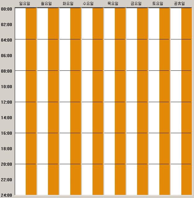
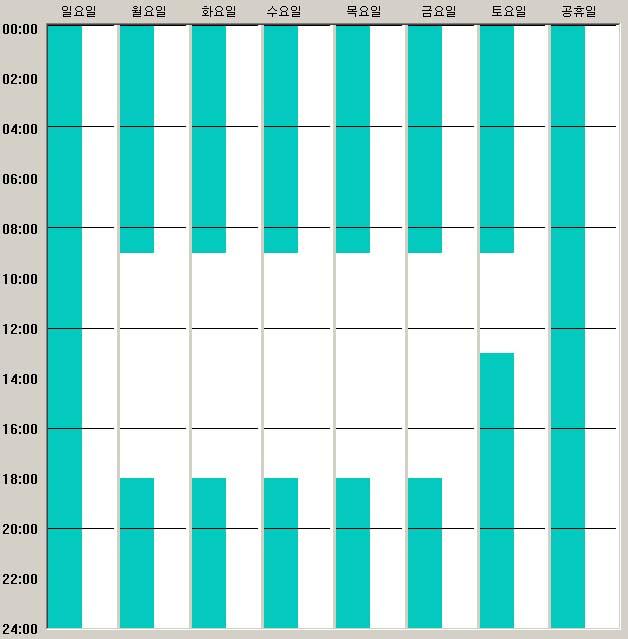
![7.2.2 Recording Schedule Set the recording schedule. [Fig. 7-4] Recording Schedule Camera List Select a camera to set a schedule. (1~16) Mode. Normal Record always.](/docs-images/90/104150313/images/82-0.jpg "Motion Record only when sensing motions. Sensor Record only when sensor senses. No Recording Delete the desired schedule. Reset Delete all the schedules.")
82 7.2.2 Recording Schedule Set the recording schedule. [Fig. 7-4] Recording Schedule Camera List Select a camera to set a schedule. (1~16) Mode. Normal Record always. Motion Record only when sensing motions. Sensor Record only when sensor senses. No Recording Delete the desired schedule. Reset Delete all the schedules. Apply To All Apply the same schedule to all the cameras. All Days Apply the same schedule everyday. Holiday Setting Designate a specific date and try recording according to a holiday setting schedule. Schedule setting Draw a schedule while pressing the mouse in accordance with a setting time. Set each camera s image quality, recording speed, pre-alarm, extended recording time, and compression mode. 82
83 [Fig. 7-5] Holiday Setting Calendar -/ Show a previous and next month. Add Add a specific date to a holiday schedule. ( ) Monthly Add Add a specific date of every month to a holiday schedule. (Monthly 13) Yearly Add Add a specific date of every year to a holiday schedule. (Yearly 06-13) They are date designated as holiday. < - Exclude a selected date from holiday setting. << - Exclude all dates from holiday setting. OK Save and close the window. Cancel Close the window without saving. 83
![[Fig. 7-6] Speed & Quality Camera Name It is the name of each camera. Image Quality Select an image quality of each camera. Normal Select a recording speed upon each camera s normal recording.](/docs-images/90/104150313/images/84-0.jpg "Motion Select a recording speed upon each camera s sensing motions. Sensor Select a recording speed upon each camera sensor s sensing.")
84 [Fig. 7-6] Speed & Quality Camera Name It is the name of each camera. Image Quality Select an image quality of each camera. Normal Select a recording speed upon each camera s normal recording. Motion Select a recording speed upon each camera s sensing motions. Sensor Select a recording speed upon each camera sensor s sensing. Pre Alarm Select a previous recording speed when each camera motion and sensor sensing. Pre Duration - Select a time period to record before each camera motion and sensor sensing. Post Duration - Select a extended recording time upon each camera motion and sensor sensing. Compression Select each camera s image compression type. (MJPEG, Enhanced) Select Window If you press the right button of the mouse twice from the camera to be changed, the select menu window appears. If you click the right button of the mouse from a certain camera out of to menus, the Apply All button appears. If you click such button, it applies to all the cameras out of menus (~) according to a certain camera s setting value. 84
![7.2.3 D/O Schedule Set the D/O schedule. [Fig. 7-7] D/O Schedule DO List Select the D/O to set the schedule. (1~8) Mode. Motion Run upon motion sensing. Sensor Run upon sensor sensing.](/docs-images/90/104150313/images/85-0.jpg "Erase Erase the desired schedule. All Days Apply the same schedule everyday. Apply To All Apply the same schedule to all the D/Os. Delete all the schedule.")
85 7.2.3 D/O Schedule Set the D/O schedule. [Fig. 7-7] D/O Schedule DO List Select the D/O to set the schedule. (1~8) Mode. Motion Run upon motion sensing. Sensor Run upon sensor sensing. Erase Erase the desired schedule. All Days Apply the same schedule everyday. Apply To All Apply the same schedule to all the D/Os. Delete all the schedule. Reset DO Schedule Preset It is the automatic schedule setting button. (Preset 1 ~ Preset 6) Holiday Setting Designate a specific date and record according to a holiday setting schedule. Schedule setting Draw a schedule while pressing the mouse at a time to set. 85


86 Preset 1 Preset 2 Preset 3 Preset 4 Preset 5 Preset 6 86
87 [Fig. 7-8] Holiday Setting Calendar -/ Show a previous and next month. Add Add a specific date to a holiday schedule. ( ) Monthly Add Add a specific date of every month to a holiday schedule. (Monthly 13) Yearly Add Add a specific date of every year to a holiday schedule. (Yearly 06-13) They are date designated as holiday. < - Exclude a selected date from holiday setting. << - Exclude all dates from holiday setting. OK Save and close the window. Cancel Close the window without saving. 87
88 7.3 DVR (2) 1610 [Fig. 7-9] DVR (2) Select DVR / Password Select the selected server. It is the place to enter the password. It is the button to enter the password. (0~9) Reset Initialize the entered password. (Used to enter the password again.) Enter Confirm the password. Try camera information & setting. Enter the sensor & alarm information. Set the recording schedule. Set the D/O schedule. Set the recording image quality and FPS. Set the motion area. 88
![7.3.1 CAMERA Try camera, sensor, D/O information and setting. [Fig. 7-10] CAMERA Camera type - NTSC/PAL (Can be set only in the server.) Change a camera name and enter up to 19 characters.](/docs-images/90/104150313/images/89-0.jpg "Pan/Tilt It is the information on Pan/Tilt set for each channel. (Can be set only in the server.) Resolution It is the information on image resolution of recorded image for each channel.")
89 7.3.1 CAMERA Try camera, sensor, D/O information and setting. [Fig. 7-10] CAMERA Camera type - NTSC/PAL (Can be set only in the server.) Change a camera name and enter up to 19 characters. Pan/Tilt It is the information on Pan/Tilt set for each channel. (Can be set only in the server.) Resolution It is the information on image resolution of recorded image for each channel. (Can be set only in the server.) 89
![7.3.2 SENSOR / DO Interface the sensor and DO. [Fig. 7-11] SENSOR / DO Sensor type Change it to an appropriate type between two types like normal close / normal open. CAMERA Means the camera.](/docs-images/90/104150313/images/90-0.jpg "Sensor Change whether to use it or not from the camera to be interfaced. (ON/OFF) Digital Out Change whether to use it or not from the camera to be interfaced.")
90 7.3.2 SENSOR / DO Interface the sensor and DO. [Fig. 7-11] SENSOR / DO Sensor type Change it to an appropriate type between two types like normal close / normal open. CAMERA Means the camera. Sensor Change whether to use it or not from the camera to be interfaced. (ON/OFF) Digital Out Change whether to use it or not from the camera to be interfaced. (ON/OFF) D/O type Change it to an appropriate type between two types like normal close / open. Basic value Change it to a basic value. (Same as the figure above.) Initialization Set not to use a sensor and digital out mode all. The sensor can run only if the recording schedule is set by sensor sensing. D/O can run only when the D/O operation schedule is set. 90
![7.3.3 SCHEDULE Set the recording schedule. [Fig. 7-12] Recording Schedule Camera Select a camera to set a schedule.](/docs-images/90/104150313/images/91-0.jpg "(116) Holiday setting Designate a specific date and record according to a holiday setting schedule. All camera Apply the same schedule to all the cameras.")
91 7.3.3 SCHEDULE Set the recording schedule. [Fig. 7-12] Recording Schedule Camera Select a camera to set a schedule. (116) Holiday setting Designate a specific date and record according to a holiday setting schedule. All camera Apply the same schedule to all the cameras. All days of the week Apply the same schedule everyday. Initialize Delete all the schedules. Always Record always. Motion Record only upon motion sensing. Sensor Record only upon sensor sensing. Audio Record only upon sound sensing. Delete Delete a desired schedule. Scheduling Draw a schedule while pressing the mouse at a time to set. Auto DVR restart Set the time to restart the DVR on everyday or a certain day of the week. (Everyday, Sunday, Monday, Tuesday, Wednesday, Thursday, Friday and Saturday) 91
92 [Fig. 7-13] Holiday Setting Calendar -/ Show a previous and next month. Add Add a specific date to a holiday schedule. ( ) Monthly Add Add a specific date of every month to a holiday schedule. (Monthly 13) Yearly Add Add a specific date of every year to a holiday schedule. (Yearly 06-13) They are date designated as holiday. < - Exclude a selected date from a holiday setting. << - Exclude all dates from a holiday setting. OK Save and close the window. Cancel Close the window without saving. 92
![7.3.4 D/O SCHEDULE Set the D/O schedule. [Fig. 7-14] D/O Schedule DIGITAL OUT Select Digital OUT to set a schedule. (18) All D/O Apply the same schedule to all the DIGITAL OUT.](/docs-images/90/104150313/images/93-0.jpg "All days of the week Apply the same schedule everyday. Initialize Delete the schedule. Motion Operate only upon motion sensing. Sensor Operate only upon sensor sensing. Delete Delete the schedule.")
93 7.3.4 D/O SCHEDULE Set the D/O schedule. [Fig. 7-14] D/O Schedule DIGITAL OUT Select Digital OUT to set a schedule. (18) All D/O Apply the same schedule to all the DIGITAL OUT. All days of the week Apply the same schedule everyday. Initialize Delete the schedule. Motion Operate only upon motion sensing. Sensor Operate only upon sensor sensing. Delete Delete the schedule. Schedule setting Draw a schedule while pressing the mouse at a time to set. (Motion takes on blue color, while the sensor does green color.) 93
![7.3.5 SPEED Set the recording speed & quality. [Fig. 7-15] Speed 1 It is the group 1,2,3 &4. Normal Set a normal recording speed. Motion Set a recording speed when sensing the motions.](/docs-images/90/104150313/images/94-0.jpg "Sensor Set a recording speed upon sensor sensing. Audio Set a recording speed upon sound sensing. All cameras Set the same recording speed for all the cameras. (Adjust it with speed control bar.")
94 7.3.5 SPEED Set the recording speed & quality. [Fig. 7-15] Speed 1 It is the group 1,2,3 &4. Normal Set a normal recording speed. Motion Set a recording speed when sensing the motions. Sensor Set a recording speed upon sensor sensing. Audio Set a recording speed upon sound sensing. All cameras Set the same recording speed for all the cameras. (Adjust it with speed control bar.) Group setting Designate groups by time zones, and set to record according to a recording schedule. Adjust the recording speed of all the cameras. Adjust the recording speed of individual cameras. 94
![[Fig. 7-16] Group Setting Indicate for each time zone. Set the group.](/docs-images/90/104150313/images/95-0.jpg "(Groups are changed every time you press it.) OK Close the window after saving.")
95 [Fig. 7-16] Group Setting Indicate for each time zone. Set the group. (Groups are changed every time you press it.) OK Close the window after saving. Cancel Close the window without saving. 95
![[Fig. 7-17] Speed 2 Set the delay time upon screen conversion. Set the recording image quality. All cameras Set the pre-alarm of all cameras equally. (Adjust it with time control bar.](/docs-images/90/104150313/images/96-0.jpg ") Compression mode Select the compression mode of recording images. (General / High compression) Adjust the pre-alarm of all cameras. Adjust the pre-alarm of individual cameras.")
96 [Fig. 7-17] Speed 2 Set the delay time upon screen conversion. Set the recording image quality. All cameras Set the pre-alarm of all cameras equally. (Adjust it with time control bar.) Compression mode Select the compression mode of recording images. (General / High compression) Adjust the pre-alarm of all cameras. Adjust the pre-alarm of individual cameras. The higher the recording 1uality is, the better the image quality is, but the more storage space is required. In case of a general compression mode, the storage capacity is large. In case of a high compression mode, the storage capacity is small, but has a low image quality. 96
97 7.3.6 MOTION / COLOR Set a motion area and colors. [Fig. 7-18] MOTION / COLOR Select the camera to set. Bright Adjust the brightness of images. Contrast Adjust the contrast of images. Tone Adjust the color tone of images. Saturation Adjust the color saturation of images. Basic value Set the initial value of bright/contrast/tone/saturation. Whole area Set the entire image as a motion sensing area. User-defined Set it as the user-defined motion sensing area. (Add, Move/Size Control & Initialize) Sensitivity Adjust the sensitivity for motion sensing. Apply all camera Apply the same to the whole camera. Adjust the image position. It is the image & motion sensing area. 97
![7.4 DVR (3) LX Series [Fig. 7-19] DVR (3) Select DVR / Password Select a server. Enter the password. Enter the password. (0~9) Reset Initialize the entered password.](/docs-images/90/104150313/images/98-0.jpg "(Used when entering the password again.) Enter Check the password again. Try camera information and setting. Set the sensor information and related channels. Enter the alarm information.")
98 7.4 DVR (3) LX Series [Fig. 7-19] DVR (3) Select DVR / Password Select a server. Enter the password. Enter the password. (0~9) Reset Initialize the entered password. (Used when entering the password again.) Enter Check the password again. Try camera information and setting. Set the sensor information and related channels. Enter the alarm information. Set the recording schedule. Set the image quality and FPS. Set the motion detecting area. 98
![7.4.1 CAMERA Indicate the camera information and name. [Fig. 7-20] CAMERA Camera type indication - NTSC/PAL (Can be set only in the server.](/docs-images/90/104150313/images/99-0.jpg ") Camera Enable / Disable Change the camera name and enter maximum 22 characters. Resolution indication It is the information on image resolutions of recorded image by channels.")
99 7.4.1 CAMERA Indicate the camera information and name. [Fig. 7-20] CAMERA Camera type indication - NTSC/PAL (Can be set only in the server.) Camera Enable / Disable Change the camera name and enter maximum 22 characters. Resolution indication It is the information on image resolutions of recorded image by channels. CIF / Half-VGA / VGA Whether to include the audio or not. 99
![7.4.2 SENSOR Set the sensor name / type and related channels. [Fig. 7-21] SENSOR Sensor name Enter the sensor name.](/docs-images/90/104150313/images/100-0.jpg "Maximum 22 characters Sensor interface camera Try multiple selection of channels for sensor recording. Sensor interface alarm Try multiple selection of alarms to operate for sensor sensing.")
100 7.4.2 SENSOR Set the sensor name / type and related channels. [Fig. 7-21] SENSOR Sensor name Enter the sensor name. Maximum 22 characters Sensor interface camera Try multiple selection of channels for sensor recording. Sensor interface alarm Try multiple selection of alarms to operate for sensor sensing. Sensor type Select the Normal Open / Normal Close. Default / Reset Select the basic value / setting release. 100
![7.4.3 SCHEDULE Set the recording schedule. [Fig. 7-22] SCHEDULE Holiday setting Users can designate a holiday and try scheduling separately.](/docs-images/90/104150313/images/101-0.jpg "Recording mode Select the continuous recording / motion / sensor / motion + sensor / recording-protection tool. Day of the week group setting 1610 can designate up to three days of the week group.")
101 7.4.3 SCHEDULE Set the recording schedule. [Fig. 7-22] SCHEDULE Holiday setting Users can designate a holiday and try scheduling separately. Recording mode Select the continuous recording / motion / sensor / motion + sensor / recording-protection tool. Day of the week group setting 1610 can designate up to three days of the week group. The group basic value is the week/holiday/weekend. You can make a schedule for each group by grouping days of the week. Users can designate a group name. Group Name Users can modify group name. All camera Apply to all cameras at the same time. All days of the week Apply to all days of the week at the same time. Initialize Clear the current setting value. To set the recording time, you can drag and drop the mouse on the desired section. 101
![7.4.4 ALARM Set the alarm name / type / delay time. [Fig. 7-23] ALARM Alarm name Enter the alarm name.](/docs-images/90/104150313/images/102-0.jpg "Maximum 22 characters Alarm type Select the Normal Open / Normal Close.")
102 7.4.4 ALARM Set the alarm name / type / delay time. [Fig. 7-23] ALARM Alarm name Enter the alarm name. Maximum 22 characters Alarm type Select the Normal Open / Normal Close. Alarm run time Once / 5 seconds ~ 10 minutes / Continue Basic value / Initialization Select the basic value / setting release. 102
![7.4.5 RECORD Set the recording image quality, FPS indication / pre & post recording times. [Fig. 7-24] RECORD Image quality Indicate the recording image quality.](/docs-images/90/104150313/images/103-0.jpg "Image FPS Indicate the recording image FPS ( Frame Per Second). Pre Recording Upon motion / sensor recording, set the previous image recording before events occur.")
103 7.4.5 RECORD Set the recording image quality, FPS indication / pre & post recording times. [Fig. 7-24] RECORD Image quality Indicate the recording image quality. Image FPS Indicate the recording image FPS ( Frame Per Second). Pre Recording Upon motion / sensor recording, set the previous image recording before events occur. (Short/middle/long hour) Post Recording Upon motion / sensor recording, set the image recording delay time after events occur. (10 sec ~ 5 minute ) 103
104 7.4.6 MOTION Set the motion sensing area, sensitivity / alarm interface. [Fig. 7-25] MOTION Select camera Select the camera to set. Motion sensing area Entire section / User definition / None Motion sensing sensitivity High / middle / low Even if you set a schedule for motion recording, you cannot have recording as long as the motion sensing area is not set. You can select / release the user-defined area setting by clicking the mouse on images. 104
105 8. ETC 8.1 Hot Key 105
106 8.1 Hot Key CTRL + Q CTRL + F1 PageUp PageDown CTRL + ALT + SHIFT + M Terminate CMS CMS Setting Live Quality Up Live Quality Down Initialize Monitor Layout 106
107 Software License Product Name CMS Number of Users 1 User Product Number The license to use this software including programs, documents, recorded media, and KEY LOCK is only given to a user or group who receives the product number. This software is protected by the program protection act and copyright laws and international copyrights treaty. All the matters on this software use comply with the software license contract. This software license serves as an evidence of purchasing the product, so it is required for further upgrade or service. So, please make sure to keep it in a safe place. 107


108 108 CMS MANUAL
The Diverse Multimedia & Surveillance System Via Dico2000 with PC DICO Operation Manual
 DICO 2000 Operation Manual Main Screen Overview IP Address & Communication Status Disk Status Screen Mode Warning Status Video Recording Status RUN Setup Search Exit SETUP The beginning ID and Password
SCode V3.5.1 (SP-601 and MP-6010) Digital Video Network Surveillance System
 Digital Video Network Surveillance System") V3.5.1 (SP-601 and MP-6010) Digital Video Network Surveillance System Core Technologies Image Compression MPEG4. It supports high compression rate with good image quality and reduces the requirement of
V3.5.1 (SP-601 and MP-6010) Digital Video Network Surveillance System Core Technologies Image Compression MPEG4. It supports high compression rate with good image quality and reduces the requirement of
SCode V3.5.1 (SP-501 and MP-9200) Digital Video Network Surveillance System
 Digital Video Network Surveillance System") V3.5.1 (SP-501 and MP-9200) Digital Video Network Surveillance System Core Technologies Image Compression MPEG4. It supports high compression rate with good image quality and reduces the requirement of
V3.5.1 (SP-501 and MP-9200) Digital Video Network Surveillance System Core Technologies Image Compression MPEG4. It supports high compression rate with good image quality and reduces the requirement of
Network Disk Recorder WJ-ND200
 Network Disk Recorder WJ-ND200 Network Disk Recorder Operating Instructions Model No. WJ-ND200 ERROR MIRROR TIMER HDD1 REC LINK /ACT OPERATE HDD2 ALARM SUSPEND ALARM BUZZER STOP Before attempting to connect
Part 1 Basic Operation
 This product is a designed for video surveillance video encode and record, it include H.264 video Compression, large HDD storage, network, embedded Linux operate system and other advanced electronic technology,
S-Series Server Setup Quiz
 1. In the System Setup window, System Information displays additional information such as: (a) IP Address (b) Modems (c) Sound Card (d) Video Channels and Audio Channels 2. You can change the Recording
Network Camera Operating Manual
 Network Camera Operating Manual Model No. WV-NW484S Before attempting to connect or operate this product, please read these instructions carefully and save this manual for future use. Preface About these
invr User s Guide Rev 1.4 (Aug. 2004)
") Contents Contents... 2 1. Program Installation... 4 2. Overview... 4 3. Top Level Menu... 4 3.1 Display Window... 9 3.1.1 Channel Status Indicator Area... 9 3.1.2. Quick Control Menu... 10 4. Detailed
Contents Contents... 2 1. Program Installation... 4 2. Overview... 4 3. Top Level Menu... 4 3.1 Display Window... 9 3.1.1 Channel Status Indicator Area... 9 3.1.2. Quick Control Menu... 10 4. Detailed
XNET-NVR User s Guide
 XNET-NVR User s Guide Ver. 1.0 (070918) 1 of 39 Table of Contents 1. Program Installation... 4 2. Overview... 4 3. Top Level Menu... 5 3.1. Display Window... 9 3.1.1. Channel Status Indicator Area... 9
Operating Instructions WV-NS950, WV-NS954 WV-NW960, WV-NW964
 Model Nos. Network Camera Operating Instructions WV-NS950, WV-NS954 WV-NW960, WV-NW964 WV-NS950 WV-NS954 WV-NW960 WV-NW964 Before attempting to connect or operate this product, please read these instructions
Intelligent Monitoring Software IMZ-RS300. Series IMZ-RS301 IMZ-RS304 IMZ-RS309 IMZ-RS316 IMZ-RS332 IMZ-RS300C
 Intelligent Monitoring Software IMZ-RS300 Series IMZ-RS301 IMZ-RS304 IMZ-RS309 IMZ-RS316 IMZ-RS332 IMZ-RS300C Flexible IP Video Monitoring With the Added Functionality of Intelligent Motion Detection With
DINOX&Digital&Video&Recorder&
 DINOX&Digital&Video&Recorder& & & & & & & & & & &&&Quick&Operation&Guide& UD.7L0X02B1228B01& Thank you for purchasing our product. If there is any question or request, please do not hesitate to contact
DVR USERS GUIDE DIGITAL VIDEO RECORDER. PC monitor. High Speed Dome Camera. H.Resolution Monitor. ISDN LAN Modem. Digital Video Recorder
 DVR DIGITAL VIDEO RECORDER USERS GUIDE PC monitor High Speed Dome Camera ISDN LAN Modem Remote Monitoring Digital Video Recorder H.Resolution Monitor Camera Controller Camera Controller SAFETY INSTRUCTIONS
Quick Operation Guide of LTN7700/7600 Series NVR
 Quick Operation Guide of LTN7700/7600 Series NVR UD.6L0202B0042A02 Thank you for purchasing our product. If there is any question or request, please do not hesitate to contact dealer. This manual is applicable
DS-7200HVI/HFI-SH Series DVR Quick Operation Guide
 DS-7200HVI/HFI-SH Series DVR Quick Operation Guide UD.6L0202B0019A01 Thank you for purchasing our product. If there is any question or request, please do not hesitate to contact dealer. This manual is
LOCAL MONITORING RECORDING HARDDISK MANAGEMENT ALARM & EXCEPTION BACKUP
 FEATURES User-friendly GUI for easy operation Up to 1024 768 resolution Simultaneous VGA and 4CIF/2CIF/CIF resolution Normal and event recording parameters configurable per individual camera Partial digital
Digital Video Recorder
 Digital Video Recorder Quick Operation Guide UD.6L0202B0067A02 Thank you for purchasing our product. If there is any question or request, please do not hesitate to contact dealer. This manual is applicable
Software Quick Manual
 XX177-24-00 Virtual Matrix Display Controller Quick Manual Vicon Industries Inc. does not warrant that the functions contained in this equipment will meet your requirements or that the operation will be
Provide144ch FREE CMS software. Time / Event / POS / Thumbnail / Panorama
 20CH DVR Real time and Playback Search Mode: Time / Event / POS / Real HD Live Display and Playback Thumbnail / Panorama Full Graphic User Interface(Multiple High-Resolution & High-Quality Language Support)
FEATURES MPEG4/MJPEG DVR
 FEATURES MPEG4/MJPEG DVR Technology Compression format providing crystal clear images with real time performance. Multiplex Allow live display, record, playback, backup and network operation at the same
CI-218 / CI-303 / CI430
 CI-218 / CI-303 / CI430 Network Camera User Manual English AREC Inc. All Rights Reserved 2017. l www.arec.com All information contained in this document is Proprietary Table of Contents 1. Overview 1.1
Triplex MPEG-4 DVR 9/16CH
 Triplex MPEG-4 DVR 9/16CH Release Version : 2.2 This document contains preliminary information and subject to change without notice. This Product is the triplex MPEG-4 DVR. THE LIST OF CONTENTS DVR SET
DS-7200HFI-SL Series DVR. Technical Specification
 DS-7200HFI-SL Series DVR Technical Specification Notices The information in this documentation is subject to change without notice and does not represent any commitment on behalf of HIKVISION. HIKVISION
Getting Started Guide for the V Series
 product pic here Getting Started Guide for the V Series Version 8.7 July 2007 Edition 3725-24476-002/A Trademark Information Polycom and the Polycom logo design are registered trademarks of Polycom, Inc.,
16CH 1080p HD-SDI Security MAGIC Lite Series DVR System - Auto detects Analog/960H/HD-SDI
 HD-SDI Magic Lite 1080p 16 CH Magic DVR detects Analog / 960H / HD-SDI camera automatically. H.264 High Compression CODEC Programmable Spot Out iphone Android remote view App Available. Crystal clear 1080p
Getting Started Guide for the V Series
 product pic here Getting Started Guide for the V Series Version 9.0.6 March 2010 Edition 3725-24476-003/A Trademark Information POLYCOM, the Polycom Triangles logo and the names and marks associated with
WV-NP1004. Network Operating Instructions. Network camera. Model No. (Lens is option.)
") Network camera Network Operating Instructions Model No. WV-NP1004 PUSH TO LOCK/EJECT WV-NP1004 (Lens is option.) Before attempting to connect or operate this product, please read these instructions carefully
Network camera Network Operating Instructions Model No. WV-NP1004 PUSH TO LOCK/EJECT WV-NP1004 (Lens is option.) Before attempting to connect or operate this product, please read these instructions carefully
NX-series User Manual
 NX-series User Manual http://www.iviewtech.com 1 CONTENT INDEX 1 NX-SERIES OVERVIEW... 4 1.1. NX-Series Features 4 1.2. NVR CONTROL PANEL 5 1.3. NVR BACK PANEL 5 2 GETTING STARTED... 8 3 LIVE VIEW... 10
DETEXI Basic Configuration
 DETEXI Network Video Management System 5.5 EXPAND YOUR CONCEPTS OF SECURITY DETEXI Basic Configuration SETUP A FUNCTIONING DETEXI NVR / CLIENT It is important to know how to properly setup the DETEXI software
DS-7204/7208/7216HVI-ST Series DVR Technical Manual
 DS-7204/7208/7216HVI-ST Series DVR Technical Manual Notices The information in this documentation is subject to change without notice and does not represent any commitment on behalf of HIKVISION. HIKVISION
MPEG4 Digital Recording System THE VXM4 RANGE FROM A NAME YOU CAN RELY ON
 MPEG Digital Recording System THE VXM RANGE FROM A NAME YOU CAN RELY ON 8 6 THE FIRST CONCEPT PRO DIGITAL RECORDING SYSTEM DESIGNED TO OUR SPECIFICATION AND FOCUSED ON YOUR REQUIREMENTS VXM KEY FEATURES
DVR-431 USB Wireless Receiver User Manual
 DVR-431 USB Wireless Receiver User Manual Thank you for using our wireless USB receiver, please read the following content carefully before using, it will help you make better use of this product. Introduction
Software Quick Manual
 XX113-30-00 Workstation and NVR Quick Manual Vicon Industries Inc. does not warrant that the functions contained in this equipment will meet your requirements or that the operation will be entirely error
ViewCommander- NVR Version 3. User s Guide
 ViewCommander- NVR Version 3 User s Guide The information in this manual is subject to change without notice. Internet Video & Imaging, Inc. assumes no responsibility or liability for any errors, inaccuracies,
DVB-T USB SET-TOP BOX
 DVB-T USB SET-TOP BOX User Manual Version: 1.0 (February 2005) TRANSYSTEM INC. No.1-2 Li-Hsin Rd.I Science-Based Industrial Park, Hsinchu, Taiwan Tel:+886-3-5780393 Fax:+886-3-5784111 e-mail: sales@transystem.com.tw
December 2006 Edition /A. Getting Started Guide for the VSX Series Version 8.6 for SCCP
 December 2006 Edition 3725-24333-001/A Getting Started Guide for the VSX Series Version 8.6 for SCCP GETTING STARTED GUIDE FOR THE VSX SERIES Trademark Information Polycom and the Polycom logo design are
DSR-3000P. Digital Video Recorder. Manual for Remote Operation by Network Connection. Bedienungsanleitung fürdie Fernbedienung über ein Netzwerk
 Digital Video Recorder DSR-3000P Manual for Remote Operation by Network Connection English GB Bedienungsanleitung fürdie Fernbedienung über ein Netzwerk Deutsch D Manuel pour la commande à distance sur
HCS-4100/50 Series Fully Digital Congress System
 HCS-4100/50 Series Application Software HCS-4100/50 application software is comprehensive, reliable and user-friendly. But it is also an easy care software system which helps the operator to manage the
WJ-HD616K/716K Quick Reference Guide
 WJ-HD616K/716K Quick Reference Guide Remote Operation Using Internet Explorer For a local operation quick guide refer to Local Quick Guide available for download http://panasonic.ca/english/customercare/operatinginstructions/query.asp
MAGICQLSeries-4CH1080pDVRSystem-SupportsEX- SDI/HD-SDI/960H/Analog/IP
 MAGICQLSeries-4CH1080pDVRSystem-SupportsEX- SDI/HD-SDI/960H/Analog/IP EX-SDI 1080p 4 CH MagicDVRdetectsAnalog/960H/EX-SDI/HD-SDIcamerasautomatically Records up to 1 IP cameras REAL-TIME Live / 1080p@ Pentaplex
PiXORD Network Video Server Recorder P-4504/8504
 PiXORD Network Video Server Recorder P-4504/8504 User s Manual Version: 1.8 Date: 08/11/2008 CONTENTS CHAPTER 1 INTRODUCTION... - 4-1. WHAT IS PIXORD NETWORK VIDEO SERVER RECORDER?...- 4-2. FEATURES...-
Magic U Series 4CH Octa-brid DVR System, 4K Output, 2 HDD slots, esata, 4CH Audio
 Magic U DVR detects Analog 960H HD-TVI A-HD EX-SDI HD-SDI cameras automatically Records up to 4 IP cameras REAL-TIME Live Programmable Multi-CH HD Spot Out 4K Video output Touch Interface iphone Android
Avigilon View Software Release Notes
 Version 4.6.5 System Version 4.6.5 includes the following components: Avigilon VIEW Version 4.6.5 R-Series Version 4.6.5 Rialto Version 4.6.5 ICVR-HD Version 3.7.3 ICVR-SD Version 2.6.3 System Requirements
MAGICUSeries-4CH1080pDVRSystem4Kouput- SupportsEX-SDI/HD-SDI/HD-TVI/A-HD/960H/Analog/ IP
 MAGICUSeries-4CH1080pDVRSystem4Kouput- SupportsEX-SDI/HD-SDI/HD-TVI/A-HD/960H/Analog/ IP Magic U 1080p 3MP 4 CH MagicUDVRdetectsAnalog/960H/HD-TVI/A-HD/EX-SDI/HD-SDIcameras automatically Records up to
MAGICLiteSeries-16CH1080pDVRSystem-SupportsEX- SDI/HD-SDI/960H/Analog/IP
 MAGICLiteSeries-16CH1080pDVRSystem-SupportsEX- SDI/HD-SDI/960H/Analog/IP EX-SDI Magic Lite 1080p 16 CH MagicDVRdetectsAnalog/960H/EX-SDI/HD-SDIcamerasautomatically Records up to 4 IP cameras REAL-TIME
Magic U Series 16CH Octa-brid DVR System, 4K Output, 8 HDD slots, esata, 16CH Audio, 4MP EX-SDI/HD-TVI Support
 Full GUI with alpha blending Individual setting of resolution frame rates and picture quality Instant Replay Digital Zoom Mouse Control Weekly scheduler with holiday by 10 minutes setting Covert Disable
February 2007 Edition /A. Getting Started Guide for the VSX Series Version 8.5.3
 February 2007 Edition 3725-21286-009/A Getting Started Guide for the VSX Series Version 8.5.3 GETTING STARTED GUIDE FOR THE VSX SERIES Trademark Information Polycom, the Polycom logo design, and ViewStation
EVD-L04/100A1-960, EVD-L08/200A1-960 and. EVD-L16/400A1-960 DVRs. Quick Operation Guide
 EVD-L04/100A1-960, EVD-L08/200A1-960 and EVD-L16/400A1-960 DVRs Quick Operation Guide Thank you for purchasing our product. If there is any question or request, please do not hesitate to contact dealer.
CCE900-IP-TR. User s Guide
 CCE900-IP-TR CCE900-IP-T & CCE900-IP-R User s Guide i-tech Company LLC TOLL FREE: (888) 483-2418 EMAIL: info@itechlcd.com WEB: www.itechlcd.com 1. Introduction The CCE900-IP-T & CCE900-IP-R is a solution
HCS-4100/20 Series Application Software
 HCS-4100/20 Series Application Software HCS-4100/20 application software is comprehensive, reliable and user-friendly. But it is also an easy care software system which helps the operator to manage the
Network Cameras User s Manual
 197Z AVI201 / 202 / 203 / 212 Network Cameras User s Manual Please read instructions thoroughly before operation and retain it for future reference. The image shown above may differ from the actual product
MAGICUSeries-32CHDVR4Koutput-SupportsEX-SDI/ HD-SDI/HD-TVI/A-HD/960H/Analog/IP
 MAGICUSeries-32CHDVR4Koutput-SupportsEX-SDI/ HD-SDI/HD-TVI/A-HD/960H/Analog/IP Magic U 1080p 3MP 32 CH MagicUDVRdetectsAnalog/960H/HD-TVI/A-HD/EX-SDI/HD-SDIcameras automatically Records up to 4 IP cameras
EVD-L04/100A1-960 EVD-L08/200A1-960 EVD-L16/400A1-960
 EVD-L04/100A1-960 EVD-L08/200A1-960 EVD-L16/400A1-960 www.eurovideo-cctv.com Main Features Main stream supports encoding at up to WD1 resolution in real time and sub stream at CIF/QCIF resolution. Simultaneous
ViewCommander-NVR. Version 6. User Guide
 ViewCommander-NVR Version 6 User Guide The information in this manual is subject to change without notice. Internet Video & Imaging, Inc. assumes no responsibility or liability for any errors, inaccuracies,
Magic U 4K Series 4CH Octa-brid DVR System, All-channel 4K Recording, 2 HDD slots, esata, 4CH Audio
 Full GUI with alpha blending Individual setting of resolution frame rates and picture quality Instant Replay Digital Zoom Mouse Control Weekly scheduler with holiday by 10 minutes setting Covert Disable
User s Manual. Network Board. Model No. WJ-HDB502
 Network Board User s Manual Model No. WJ-HDB502 Before attempting to connect or operate this product, please read these instructions carefully and save this manual for future use. CONTENTS Introduction...
DS-7200HVI-ST/RW Series DVR. Technical Manual
 DS-7200HVI-ST/RW Series DVR Technical Manual Notices The information in this documentation is subject to change without notice and does not represent any commitment on behalf of HIKVISION. HIKVISION disclaims
EdgeConnect Module Quick Start Guide ITERIS INNOVATION FOR BETTER MOBILITY
 EdgeConnect Module Quick Start Guide ITERIS INNOVATION FOR BETTER MOBILITY 493456301 Rev B April 2009 Table of Contents Installation... 1 Setup... 2 Operation... 4 Live Video... 4 Video Settings... 5 Network
MPEG4 Digital Recording System THE VXM4B RANGE 100 IPS
 MPEG Digital Recording System THE VXMB RANGE 00 IPS 8 6 THE FIRST CONCEPT PRO DIGITAL RECORDING SYSTEM DESIGNED TO OUR SPECIFICATION AND FOCUSED ON YOUR REQUIREMENTS VXMB KEY FEATURES Enhanced Graphical
RS Part No Instruction Manual Solid State DVR. (Single Chanel for Mobile) SSD01CA
 SSD01CA") RS Part No. 696-1210 Instruction Manual Solid State DVR (Single Chanel for Mobile) RS PART NO.: 696-1210 MJPEG 1CH CAR DVR (Compact size 1ch Stand Alone DVR) Simple & Max Low cost but great guality MJPEG
RS Part No. 696-1210 Instruction Manual Solid State DVR (Single Chanel for Mobile) RS PART NO.: 696-1210 MJPEG 1CH CAR DVR (Compact size 1ch Stand Alone DVR) Simple & Max Low cost but great guality MJPEG
May 2006 Edition /A. Getting Started Guide for the VSX Series Version 8.5
 May 2006 Edition 3725-21286-008/A Getting Started Guide for the VSX Series Version 8.5 GETTING STARTED GUIDE FOR THE VSX SERIES Trademark Information Polycom, the Polycom logo design, and ViewStation are
Software Quick Manual
 XX113-30-01 Workstation and NVR Quick Manual Vicon Industries Inc. does not warrant that the functions contained in this equipment will meet your requirements or that the operation will be entirely error
Striking Clarity, Unparalleled Flexibility, Precision Control
 Striking Clarity, Unparalleled Flexibility, Precision Control Product Brochures English 460XW 460C 460C 800 ieditor The - tents and processed camera inputs to provide the monitoring by supporting camera
GV-3D People Counter 3DPCV10-A
 GV-3D People Counter User's Manual Before attempting to connect or operate this product, please read these instructions carefully and save this manual for future use. 3DPCV10-A 2013 GeoVision, Inc. All
MAGICUSeries-16CHDVR4Koutput-SupportsEX-SDI/ HD-SDI/HD-TVI/A-HD/960H/Analog/IP
 MAGICUSeries-16CHDVR4Koutput-SupportsEX-SDI/ HD-SDI/HD-TVI/A-HD/960H/Analog/IP EX-SDI Magic U 1080p 16 CH MagicUDVRdetectsAnalog/960H/HD-TVI/A-HD/EX-SDI/HD-SDIcameras automatically Records up to 4 IP cameras
Total MPEG4/JPEG DVR Solution Provider Intelligent Multiplex DVR!
 Total MPEG4/JPEG DVR Solution Provider Intelligent Multiplex DVR! Best Digital Video Networking Solutions for Complete Security Application ANX-16480 / 8240 / 4120D MPEG4 max. 480 / 240 / 120fps 8/ 8/
Operating Instructions
 Operating Instructions Network Disk Recorder Model No. WJ-NX200K/G Network Disk Recorder WJ-NX200 Before attempting to connect or operate this product, please read these instructions carefully and save
Precautions and Disclaimers What You Can Do with Geometry Manager Pro Check Your Computer System requirements...
 Operating Instructions Geometric & Setup Management Software Windows Geometry Manager Pro Ver. 4.0 Thank you for purchasing this Panasonic product. Before using this software, please read the instructions
IP Broadcasting System. User manual
 IP Broadcasting System User manual 1. IP Broadcast System Hardware and Operating System Demands 1.1 Lowest Demands of Computer Hardware I. CPU : Intel Core Quad 3.0GHz II. RAM : 4GB III. Standard sound
EasyNet-HD Digital Video Recorder. Compact Series 4/8/16ch
 EasyNet-HD Digital Video Recorder Compact Series 4/8/16ch Thank you for using our product. 1. This is user's manual for EasyNet-HD Compact Series DVR Models 2. This manual contains product specification
8 CH MJPEG DVR USER MANUAL
 8 CH MJPEG DVR USER MANUAL Contents 1. SAFETY PRECAUTIONS... 3 2. FEATURES... 4 3. PACKING LIST... 5 4. NAME and FUNCTION of EACH PART... 6 4.1 FRONT PANEL BUTTONS and CONTROLS... 6 4.2 REAR PANEL BUTTONS
For high performance video recording and visual alarm verification solution, TeleEye RX is your right choice!
 TeleEye RX carries a range of professional digital video recording servers, which is designed to operate on diverse network environment and fully utilize the existing network bandwidth with optimal performance.
LedSet User s Manual V Official website: 1 /
 LedSet User s Manual V2.6.1 1 / 42 20171123 Contents 1. Interface... 3 1.1. Option Menu... 4 1.1.1. Screen Configuration... 4 1.1.1.1. Instruction to Sender/ Receiver/ Display Connection... 4 1.1.1.2.
User s Guide W-E
 Presto! PVR ISDB User s Guide 518100-02-01-W-E-112307-02 Copyright 2007, NewSoft Technology Corp. All Rights Reserved. No portion of this document may be copied or reproduced in any manner without prior
This document contains the latest information about the new Polycom VS4000 TM model, running 5.1 software.
 This document contains the latest information about the new Polycom VS4000 TM model, running 5.1 software. What s New? The VS4000 is now available in a compact form factor, making it even easier to integrate
Owner's Manual. TOUCH SCREEN CONTROLLER for Air Conditioning Control System. Model BMS-CT5120UL. English
 TOUCH SCREEN CONTROLLER for Air Conditioning Control System Model BMS-CT5120UL English Contents 1 Precautions for safety.................................................. 5 2 Main functions........................................................
DIVISION 28. systems. conditions. GENERAL PART 1 PART 2 PRODUCTS. Products, Inc. (2) The. (3) The one modules. (4) The. to CD-R, CD- technology.
 The. (3) The one modules. (4) The. to CD-R, CD- technology.") VITEK CHRONO SERIES 8 CHANNEL DIGITAL VIDEO RECORDER DIVISION 28 ELECTRONIC SAFETY AND SECURITY 28 20 00 ELECTRONICC SURVEILLANCE 28 23 00 VIDEO SURVEILLANCE 28 23 29 VIDEO SURVEILLANCE REMOTE DEVICES
VITEK CHRONO SERIES 8 CHANNEL DIGITAL VIDEO RECORDER DIVISION 28 ELECTRONIC SAFETY AND SECURITY 28 20 00 ELECTRONICC SURVEILLANCE 28 23 00 VIDEO SURVEILLANCE 28 23 29 VIDEO SURVEILLANCE REMOTE DEVICES
DVB-T Box, USB Monheim/Germany Tel. +49 (0)9091/ Fax +49 (0)9091/ Hama GmbH & Co KG.
9091/ Fax +49 (0)9091/ Hama GmbH & Co KG.") www.hama.de Hama GmbH & Co KG Postfach 80 86651 Monheim/Germany Tel. +49 (0)9091/502-0 Fax +49 (0)9091/502-274 hama@hama.de www.hama.de 00062776-01.05 DVB-T Box, USB 2.0 00062776 L TV USB receiver User
www.hama.de Hama GmbH & Co KG Postfach 80 86651 Monheim/Germany Tel. +49 (0)9091/502-0 Fax +49 (0)9091/502-274 hama@hama.de www.hama.de 00062776-01.05 DVB-T Box, USB 2.0 00062776 L TV USB receiver User
Refer to the included CD-ROM for the German, French, Spanish and Italian Manual for Remote Operation by Network Connection. Die Bedienungsanleitung
 Refer to the included CD-ROM for the German, French, Spanish and Italian Manual for Remote Operation by Network Connection. Die Bedienungsanleitung für die Fernbedienung über ein Netzwerk in den Sprachen
Sales Alert: ViconNet 4.0 and Virtual Matrix Controller
 Volume XVI, Number 8 August 1, 2007 Vicon Industries Inc. 1967 2007 Sales Alert: ViconNet 4.0 and Virtual Matrix Controller INSIDE THIS ISSUE: Introduction Page 1 ViconNet 4.0 New Feature Highlights ViconNet
PYROPTIX TM IMAGE PROCESSING SOFTWARE
 Innovative Technologies for Maximum Efficiency PYROPTIX TM IMAGE PROCESSING SOFTWARE V1.0 SOFTWARE GUIDE 2017 Enertechnix Inc. PyrOptix Image Processing Software v1.0 Section Index 1. Software Overview...
QUICK START GUIDE QT ANALOG HD CAMERA & DVR BUNDLE ENGLISH
 QUICK START GUIDE QT ANALOG HD CAMERA & DVR BUNDLE ENGLISH Table of Contents Welcome What s Included...3 Understanding your DVR...4 Get Connected Registration...5 Connect Your Cameras...5 Connect DVR to
User Manual V2.2 DVR. Notice: This content is subject to be change without notice. User Manual 1
 V2.2 User Manual DVR Notice: This content is subject to be change without notice. User Manual 1 WARNING TO REDUCE THE RISK OF FIRE OR ELECTRIC SHOCK, DO NOT EXPOSE THIS APPLIANCE TO RAIN OR MOIS- TURE.
ES-RN A ES-RN A Series NVR. Technical Specification
 ES-RN080802-A ES-RN160802-A Series NVR Technical Specification NOTICES The information in this documentation is subject to change without notice and does not represent any commitment on behalf of EMERSON.
D-Lab & D-Lab Control Plan. Measure. Analyse. User Manual
 D-Lab & D-Lab Control Plan. Measure. Analyse User Manual Valid for D-Lab Versions 2.0 and 2.1 September 2011 Contents Contents 1 Initial Steps... 6 1.1 Scope of Supply... 6 1.1.1 Optional Upgrades... 6
Statement SmartLCT User s Manual Welcome to use the product from Xi an NovaStar Tech Co., Ltd. (hereinafter referred to as NovaStar ). It is our great
. It is our great") LED Display Configuration Software SmartLCT User s Manual Software Version: V3.0 Rev3.0.0 NS110100239 Statement SmartLCT User s Manual Welcome to use the product from Xi an NovaStar Tech Co., Ltd. (hereinafter
LED Display Configuration Software SmartLCT User s Manual Software Version: V3.0 Rev3.0.0 NS110100239 Statement SmartLCT User s Manual Welcome to use the product from Xi an NovaStar Tech Co., Ltd. (hereinafter
Wireless Cloud Camera TV-IP751WC (v1.0r)
") TRENDnet s, model, takes the work out of viewing video over the internet. Previously to view video remotely, users needed to perform many complicated and time consuming steps: such as signing up for a
TRENDnet s, model, takes the work out of viewing video over the internet. Previously to view video remotely, users needed to perform many complicated and time consuming steps: such as signing up for a
MPEG4 Mobile DVR User Manual
 MPEG4 Mobile DVR User Manual 1 MPEG4 Embedded User Manual A. Installation Environment Installation Guideline In order to ensure the safety with the DVR product and maximize product performance, keep DVR
AMIQ-K2 Program for Transferring Various-Format I/Q Data to AMIQ. Products: AMIQ, SMIQ
 Products: AMIQ, SMIQ AMIQ-K2 Program for Transferring Various-Format I/Q Data to AMIQ The software AMIQ-K2 enables you to read, convert, and transfer various-format I/Q data files to AMIQ format. AMIQ-K2
SNR Playback Viewer SNR Version 1.9.7
 User Manual SNR Playback Viewer SNR Version 1.9.7 Modular Network Video Recorder Note: To ensure proper operation, please read this manual thoroughly before using the product and retain the information
4CH DVR, AS-DVR004A. AL - Aswar Trading Group Co., FEATURES. Pentplex ( Recording, Playback, Network simultaneously ) Up to 60fps Recording Speed
 Up to 60fps Recording Speed") 4CH DVR, AS-DVR004A FEATURES Pentplex ( Recording, Playback, Network simultaneously ) Up to 60fps Recording Speed USB flash disk backup Adjust Up/Down/Left/Right screen position Video Input signal: NTSC/PAL
4CH DVR, AS-DVR004A FEATURES Pentplex ( Recording, Playback, Network simultaneously ) Up to 60fps Recording Speed USB flash disk backup Adjust Up/Down/Left/Right screen position Video Input signal: NTSC/PAL
Digital Video User s Guide THE FUTURE NOW SHOWING
 Digital Video User s Guide THE FUTURE NOW SHOWING TV Welcome The NEW WAY to WATCH Digital TV is different than anything you have seen before. It isn t cable it s better! Digital TV offers great channels,
EtherneTV-STB Set Top Box
 EtherneTV-STB Set Top Box Set Top Box v3.7.3b Quick Start Guide September 14, 2006 4410-0134-0005 Copyright 2006 VBrick Systems, Inc. All rights reserved. 12 Beaumont Road Wallingford, Connecticut 06492,
VIDEO GRABBER. DisplayPort. User Manual
 VIDEO GRABBER DisplayPort User Manual Version Date Description Author 1.0 2016.03.02 New document MM 1.1 2016.11.02 Revised to match 1.5 device firmware version MM 1.2 2019.11.28 Drawings changes MM 2
USER MANUAL V /16CH DVR. This document contains preliminary information and subject to change without notice.
 V. 1.3 USER MANUAL 8/16CH DVR This document contains preliminary information and subject to change without notice. WARNING TO REDUCE THE RISK OF FIRE OR ELECTRIC SHOCK, DO NOT EXPOSE THIS APPLIANCE TO
NSU Distance Delivery Teleconference Operations Polycom 2005
 NSU Distance Delivery Teleconference Operations Polycom 2005 Polycom Teleconference & Crestron Control Presentation Room Operations E-learning Studio Mode Classroom Presentation Mode DDN Remote Site Capability
Rifatron Co., Ltd. Technology beyond the view
 Technology beyond the view FOR FURTHER INFORMATION PLEASE CONTACT Rifatron Co., Ltd. Website : www.rifatron.com 9th FL., Rifatron Bldg., 736-8, Banpo-dong, Seocho-gu, Seoul, Korea 137-810 Tel +82 2 2015
HD SDI Cameras. = XON Tri-brid NDVR
 X-ON NDVR Concept The X-ON line up of Recording Server from Versiton is analytic powerhouse, highly-scalable, and IT friendly. The X-ON is designed to meet the complex application and integration requirements
Preface... Specification...14
 Contents for V680L Operating Manual Preface......3 Important safety tips...3 Accessories of product...4 Icons of product...5 Installation support...7 Description for operating steps... 8 Description for
HD1080P 4 Camera CCTV System
 HD 1080P HD1080P 4 Camera CCTV System User Guide Version 1 Contents CHAPTER 1 FUNCTION DESCRIPTIONS AND FEATURES... 1 CHAPTER 2 CAMERA INSTALLATION... 2 2.1 BULLET CAMERA INSTALLATION... 2 2.1 DOME CAMERA